EP1211115B1 - Clip for fixing strips - Google Patents
Clip for fixing strips Download PDFInfo
- Publication number
- EP1211115B1 EP1211115B1 EP01309810A EP01309810A EP1211115B1 EP 1211115 B1 EP1211115 B1 EP 1211115B1 EP 01309810 A EP01309810 A EP 01309810A EP 01309810 A EP01309810 A EP 01309810A EP 1211115 B1 EP1211115 B1 EP 1211115B1
- Authority
- EP
- European Patent Office
- Prior art keywords
- latching
- snap
- receiving slot
- strip
- clip
- Prior art date
- Legal status (The legal status is an assumption and is not a legal conclusion. Google has not performed a legal analysis and makes no representation as to the accuracy of the status listed.)
- Expired - Lifetime
Links
- 238000004519 manufacturing process Methods 0.000 description 2
- 230000004075 alteration Effects 0.000 description 1
- 238000001746 injection moulding Methods 0.000 description 1
- 238000000034 method Methods 0.000 description 1
Images
Classifications
-
- F—MECHANICAL ENGINEERING; LIGHTING; HEATING; WEAPONS; BLASTING
- F16—ENGINEERING ELEMENTS AND UNITS; GENERAL MEASURES FOR PRODUCING AND MAINTAINING EFFECTIVE FUNCTIONING OF MACHINES OR INSTALLATIONS; THERMAL INSULATION IN GENERAL
- F16B—DEVICES FOR FASTENING OR SECURING CONSTRUCTIONAL ELEMENTS OR MACHINE PARTS TOGETHER, e.g. NAILS, BOLTS, CIRCLIPS, CLAMPS, CLIPS OR WEDGES; JOINTS OR JOINTING
- F16B5/00—Joining sheets or plates, e.g. panels, to one another or to strips or bars parallel to them
- F16B5/12—Fastening strips or bars to sheets or plates, e.g. rubber strips, decorative strips for motor vehicles, by means of clips
- F16B5/123—Auxiliary fasteners specially designed for this purpose
-
- B—PERFORMING OPERATIONS; TRANSPORTING
- B60—VEHICLES IN GENERAL
- B60J—WINDOWS, WINDSCREENS, NON-FIXED ROOFS, DOORS, OR SIMILAR DEVICES FOR VEHICLES; REMOVABLE EXTERNAL PROTECTIVE COVERINGS SPECIALLY ADAPTED FOR VEHICLES
- B60J10/00—Sealing arrangements
- B60J10/30—Sealing arrangements characterised by the fastening means
-
- B—PERFORMING OPERATIONS; TRANSPORTING
- B60—VEHICLES IN GENERAL
- B60J—WINDOWS, WINDSCREENS, NON-FIXED ROOFS, DOORS, OR SIMILAR DEVICES FOR VEHICLES; REMOVABLE EXTERNAL PROTECTIVE COVERINGS SPECIALLY ADAPTED FOR VEHICLES
- B60J10/00—Sealing arrangements
- B60J10/70—Sealing arrangements specially adapted for windows or windscreens
-
- F—MECHANICAL ENGINEERING; LIGHTING; HEATING; WEAPONS; BLASTING
- F16—ENGINEERING ELEMENTS AND UNITS; GENERAL MEASURES FOR PRODUCING AND MAINTAINING EFFECTIVE FUNCTIONING OF MACHINES OR INSTALLATIONS; THERMAL INSULATION IN GENERAL
- F16B—DEVICES FOR FASTENING OR SECURING CONSTRUCTIONAL ELEMENTS OR MACHINE PARTS TOGETHER, e.g. NAILS, BOLTS, CIRCLIPS, CLAMPS, CLIPS OR WEDGES; JOINTS OR JOINTING
- F16B5/00—Joining sheets or plates, e.g. panels, to one another or to strips or bars parallel to them
- F16B5/12—Fastening strips or bars to sheets or plates, e.g. rubber strips, decorative strips for motor vehicles, by means of clips
- F16B5/126—Fastening strips or bars to sheets or plates, e.g. rubber strips, decorative strips for motor vehicles, by means of clips at least one of the sheets, plates, bars or strips having integrally formed or integrally connected snap-in-features
-
- Y—GENERAL TAGGING OF NEW TECHNOLOGICAL DEVELOPMENTS; GENERAL TAGGING OF CROSS-SECTIONAL TECHNOLOGIES SPANNING OVER SEVERAL SECTIONS OF THE IPC; TECHNICAL SUBJECTS COVERED BY FORMER USPC CROSS-REFERENCE ART COLLECTIONS [XRACs] AND DIGESTS
- Y10—TECHNICAL SUBJECTS COVERED BY FORMER USPC
- Y10T—TECHNICAL SUBJECTS COVERED BY FORMER US CLASSIFICATION
- Y10T24/00—Buckles, buttons, clasps, etc.
- Y10T24/13—Article holder attachable to apparel or body
- Y10T24/1394—Article held by clip
-
- Y—GENERAL TAGGING OF NEW TECHNOLOGICAL DEVELOPMENTS; GENERAL TAGGING OF CROSS-SECTIONAL TECHNOLOGIES SPANNING OVER SEVERAL SECTIONS OF THE IPC; TECHNICAL SUBJECTS COVERED BY FORMER USPC CROSS-REFERENCE ART COLLECTIONS [XRACs] AND DIGESTS
- Y10—TECHNICAL SUBJECTS COVERED BY FORMER USPC
- Y10T—TECHNICAL SUBJECTS COVERED BY FORMER US CLASSIFICATION
- Y10T24/00—Buckles, buttons, clasps, etc.
- Y10T24/30—Trim molding fastener
- Y10T24/309—Plastic type
-
- Y—GENERAL TAGGING OF NEW TECHNOLOGICAL DEVELOPMENTS; GENERAL TAGGING OF CROSS-SECTIONAL TECHNOLOGIES SPANNING OVER SEVERAL SECTIONS OF THE IPC; TECHNICAL SUBJECTS COVERED BY FORMER USPC CROSS-REFERENCE ART COLLECTIONS [XRACs] AND DIGESTS
- Y10—TECHNICAL SUBJECTS COVERED BY FORMER USPC
- Y10T—TECHNICAL SUBJECTS COVERED BY FORMER US CLASSIFICATION
- Y10T24/00—Buckles, buttons, clasps, etc.
- Y10T24/44—Clasp, clip, support-clamp, or required component thereof
- Y10T24/44291—Clasp, clip, support-clamp, or required component thereof including pivoted gripping member
- Y10T24/44342—Clasp, clip, support-clamp, or required component thereof including pivoted gripping member having rigid linking arm pivotally connected to each gripping member
-
- Y—GENERAL TAGGING OF NEW TECHNOLOGICAL DEVELOPMENTS; GENERAL TAGGING OF CROSS-SECTIONAL TECHNOLOGIES SPANNING OVER SEVERAL SECTIONS OF THE IPC; TECHNICAL SUBJECTS COVERED BY FORMER USPC CROSS-REFERENCE ART COLLECTIONS [XRACs] AND DIGESTS
- Y10—TECHNICAL SUBJECTS COVERED BY FORMER USPC
- Y10T—TECHNICAL SUBJECTS COVERED BY FORMER US CLASSIFICATION
- Y10T24/00—Buckles, buttons, clasps, etc.
- Y10T24/44—Clasp, clip, support-clamp, or required component thereof
- Y10T24/44291—Clasp, clip, support-clamp, or required component thereof including pivoted gripping member
- Y10T24/44376—Spring or resiliently biased about pivot
- Y10T24/44385—Distinct spring
- Y10T24/44402—Distinct spring with operator for moving pivoted member
- Y10T24/4441—Camming or wedging element
-
- Y—GENERAL TAGGING OF NEW TECHNOLOGICAL DEVELOPMENTS; GENERAL TAGGING OF CROSS-SECTIONAL TECHNOLOGIES SPANNING OVER SEVERAL SECTIONS OF THE IPC; TECHNICAL SUBJECTS COVERED BY FORMER USPC CROSS-REFERENCE ART COLLECTIONS [XRACs] AND DIGESTS
- Y10—TECHNICAL SUBJECTS COVERED BY FORMER USPC
- Y10T—TECHNICAL SUBJECTS COVERED BY FORMER US CLASSIFICATION
- Y10T24/00—Buckles, buttons, clasps, etc.
- Y10T24/44—Clasp, clip, support-clamp, or required component thereof
- Y10T24/44291—Clasp, clip, support-clamp, or required component thereof including pivoted gripping member
- Y10T24/44496—Clasp, clip, support-clamp, or required component thereof including pivoted gripping member with operator means for moving pivoted member
- Y10T24/44513—Camming or wedging element
-
- Y—GENERAL TAGGING OF NEW TECHNOLOGICAL DEVELOPMENTS; GENERAL TAGGING OF CROSS-SECTIONAL TECHNOLOGIES SPANNING OVER SEVERAL SECTIONS OF THE IPC; TECHNICAL SUBJECTS COVERED BY FORMER USPC CROSS-REFERENCE ART COLLECTIONS [XRACs] AND DIGESTS
- Y10—TECHNICAL SUBJECTS COVERED BY FORMER USPC
- Y10T—TECHNICAL SUBJECTS COVERED BY FORMER US CLASSIFICATION
- Y10T24/00—Buckles, buttons, clasps, etc.
- Y10T24/44—Clasp, clip, support-clamp, or required component thereof
- Y10T24/44573—Clasp, clip, support-clamp, or required component thereof including track or way guided and retained gripping member
Definitions
- the present invention relates to a clip arrangement for fixing a strip to a structure.
- Clip arrangements of this type as for example disclosed in GB 2047785A, are used, in particular, for fixing decorative strips, in particular decorative strips as a window surround, in vehicles.
- latching means which have a plurality of teeth arranged in series so the decorative strips can be fixed at different depths according to manufacturing tolerances and irregularities in each case.
- a disadvantage in these arrangements can be that the force for applying a decorative strip increases with increasing depth of fixing which can lead to damage to the strip or makes automation of the handling process difficult.
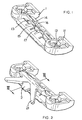
- Fig. 1 shows a retaining part 1 which can be fixed to a structure, not shown, by means of one or more retaining devices 11. Fixing is typically by means of fixing elements, for example studs welded onto the structure and engaging in receiving openings 12 in the mountings 11.
- the retaining part 1 has a receiving slot which is limited by an upper guide 14 and a lower guide 17.
- the upper guide 14 and the lower guide 17 are preferably formed by a plurality of individual portions which are designed, in particular, in such a way that the whole part can be readily demoulded during production by injection moulding.
- At least one latching finger 15 directed obliquely into the receiving slot 13 and with a latching opening 16 at its free end projects somewhat into the receiving slot 13.
- Fig. 2 shows the retaining part according to Fig. 2 with an inserted snap-on part 2.
- This snap-on part 2 is formed in such a way, for example with projecting retaining wings 21, that it can initially be fixed in a decorative strip, not shown here, and is used for the later fixing of this decorative strip on the retaining part 1.
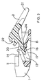
- Fig. 3 shows a cross-section along the line III-III through the arrangement in Fig. 2.
- a strip not shown, can be fixed to the snap-on part 2 by means of a retaining groove 22 in cooperation with the retaining wings 21.
- the strip with the snap-on part is then fixed in the retaining part 1 while a projection 23 with a plurality of latching lugs 24 and projecting out of the snap-on part 2 is inserted in the receiving slot 13 until one of the latching lugs 24 latches into the latching opening 16 of a latching finger 15 in a suitable position.
- the upper guide 14 and the lower guide 17 guide the projection 23 very precisely into the desired position and allow no alteration of position upwards or downwards.
- latching fingers 15 allow them to gently spring back and yield to the latching lugs 24 when the projection 23 is pushed into the receiving slot 13.
- the illustrated designs of latching opening 16 and latching lug 24 are particularly advantageous, although other structures of the barbed type could also be used at these points.
- the present invention has the advantage that a strip can be fixed at different depths with constant force, a great retaining force simultaneously preventing later detachment.
Description
- The present invention relates to a clip arrangement for fixing a strip to a structure. Clip arrangements of this type, as for example disclosed in GB 2047785A, are used, in particular, for fixing decorative strips, in particular decorative strips as a window surround, in vehicles.
- In known arrangements, latching means are available which have a plurality of teeth arranged in series so the decorative strips can be fixed at different depths according to manufacturing tolerances and irregularities in each case. A disadvantage in these arrangements can be that the force for applying a decorative strip increases with increasing depth of fixing which can lead to damage to the strip or makes automation of the handling process difficult.
- It is the object of the present invention to provide a clip arrangement in which the force for fixing a strip is substantially independent of the depth of fixing, but in which nevertheless great resistance to dismantling occurs.
- The object is achieved by a clip according to claim 1.
- Details of the invention are exemplarily described by means of a preferred embodiment, to which the invention is, however, not limited, with the aid of the drawings, in which:
- Fig. 1 is a perspective view of a retaining part according to the invention,
- Fig. 2 shows the retaining part in Fig. 1 with inserted snap-on part and
- Fig. 3 is a cross-section through Fig. 2 along the line III-III.
- Fig. 1 shows a retaining part 1 which can be fixed to a structure, not shown, by means of one or more retaining devices 11. Fixing is typically by means of fixing elements, for example studs welded onto the structure and engaging in receiving
openings 12 in the mountings 11. The retaining part 1 has a receiving slot which is limited by anupper guide 14 and alower guide 17. Theupper guide 14 and thelower guide 17 are preferably formed by a plurality of individual portions which are designed, in particular, in such a way that the whole part can be readily demoulded during production by injection moulding. At least one latchingfinger 15 directed obliquely into thereceiving slot 13 and with a latching opening 16 at its free end projects somewhat into thereceiving slot 13. - Fig. 2 shows the retaining part according to Fig. 2 with an inserted snap-on
part 2. This snap-onpart 2 is formed in such a way, for example with projecting retainingwings 21, that it can initially be fixed in a decorative strip, not shown here, and is used for the later fixing of this decorative strip on the retaining part 1. - For a better view of the entire arrangement, Fig. 3 shows a cross-section along the line III-III through the arrangement in Fig. 2. It can be seen that a strip, not shown, can be fixed to the snap-on
part 2 by means of aretaining groove 22 in cooperation with theretaining wings 21. The strip with the snap-on part is then fixed in the retaining part 1 while aprojection 23 with a plurality oflatching lugs 24 and projecting out of the snap-onpart 2 is inserted in thereceiving slot 13 until one of thelatching lugs 24 latches into the latching opening 16 of alatching finger 15 in a suitable position. Theupper guide 14 and thelower guide 17 guide theprojection 23 very precisely into the desired position and allow no alteration of position upwards or downwards. The length and shape of thelatching fingers 15 allows them to gently spring back and yield to thelatching lugs 24 when theprojection 23 is pushed into thereceiving slot 13. The oblique position of thelatching fingers 15, however, in cooperation with the barb-like structure oflatching lugs 24 and latchingopenings 16, causes very high forces to secure the snap-on part against withdrawal. The illustrated designs of latching opening 16 andlatching lug 24 are particularly advantageous, although other structures of the barbed type could also be used at these points. - The present invention has the advantage that a strip can be fixed at different depths with constant force, a great retaining force simultaneously preventing later detachment.
Claims (2)
- Clip arrangement for fixing a strip, in particular a decorative strip in a vehicle, with a retaining part (1) and a snap-on part (2), wherein the retaining part has a receiving slot (13) with an upper guide (14) and a lower guide (17), into which receiving slot (13) there projects obliquely at least one latching finger (15) having a latching opening (16) at its free end, wherein the snap-on part (2) also has at least one projection (23) with a plurality of latching lugs (24) which can latch with the latching opening (16) when the projection (23) is inserted into the receiving slot (13) of the retaining part (1).
- Clip arrangement according to claim 1, wherein each latching finger (15) is designed and directed in such a way that it can gently yield to the latching lugs (24) when the projection (23) is inserted into the receiving slot (13), but prevents the snap-on part (2) from being withdrawn after the latching lugs (24) have been latched into latching openings (16).
Applications Claiming Priority (2)
| Application Number | Priority Date | Filing Date | Title |
|---|---|---|---|
| DE10059289A DE10059289A1 (en) | 2000-11-29 | 2000-11-29 | Clip for fastening strips |
| DE10059289 | 2000-11-29 |
Publications (3)
| Publication Number | Publication Date |
|---|---|
| EP1211115A2 EP1211115A2 (en) | 2002-06-05 |
| EP1211115A3 EP1211115A3 (en) | 2002-12-18 |
| EP1211115B1 true EP1211115B1 (en) | 2007-01-10 |
Family
ID=7665123
Family Applications (1)
| Application Number | Title | Priority Date | Filing Date |
|---|---|---|---|
| EP01309810A Expired - Lifetime EP1211115B1 (en) | 2000-11-29 | 2001-11-21 | Clip for fixing strips |
Country Status (5)
| Country | Link |
|---|---|
| US (1) | US6530130B2 (en) |
| EP (1) | EP1211115B1 (en) |
| JP (1) | JP2002235712A (en) |
| DE (2) | DE10059289A1 (en) |
| ES (1) | ES2278701T3 (en) |
Cited By (2)
| Publication number | Priority date | Publication date | Assignee | Title |
|---|---|---|---|---|
| DE202010008001U1 (en) | 2010-07-07 | 2010-09-02 | Newfrey Llc, Newark | Clip for attaching a bar or rib |
| DE102010016434A1 (en) | 2010-04-14 | 2011-10-20 | Audi Ag | Clip for fastening support member, preferably on motor vehicle, comprises support anchoring unit, retaining unit and receiving slot with insertion opening |
Families Citing this family (6)
| Publication number | Priority date | Publication date | Assignee | Title |
|---|---|---|---|---|
| JP2004125122A (en) * | 2002-10-04 | 2004-04-22 | Honda Motor Co Ltd | Clip for molding attachment |
| DE102005015762A1 (en) * | 2005-03-30 | 2006-08-24 | Decoma (Germany) Gmbh | Holding device for connecting guide rail with fixed side window, has clamping device in front functional part for clamping guide rail and rear locking in back functional part for retaining plate in positive-fit manner |
| FR2905431B1 (en) * | 2006-08-29 | 2010-10-22 | Raymond A & Cie | DEVICE FOR MAINTAINING TRIM |
| WO2009148721A1 (en) | 2008-06-06 | 2009-12-10 | Illinois Tool Works Inc. | Compensating position roof ditch molding retainer |
| DE102013201561A1 (en) * | 2013-01-30 | 2014-07-31 | Decoma (Germany) Gmbh | fastener |
| CN111271867A (en) * | 2018-12-21 | 2020-06-12 | 奥克斯空调股份有限公司 | Air conditioner |
Family Cites Families (11)
| Publication number | Priority date | Publication date | Assignee | Title |
|---|---|---|---|---|
| GB2047785A (en) * | 1979-04-17 | 1980-12-03 | United Carr Ltd | Windshield moulding clip |
| US4557503A (en) * | 1982-03-25 | 1985-12-10 | Linn Maynard W | Binding unit |
| DE3441302C1 (en) * | 1984-11-12 | 1986-04-10 | Guido, Jürgen, Dipl.-Ing., 8402 Neutraubling | Pipe clamp made of resilient material |
| GB2193930B (en) * | 1986-02-07 | 1989-11-01 | Britax Weathershields | Vehicle opening roof |
| DE4117114C1 (en) * | 1991-05-25 | 1992-08-06 | A. Raymond Kg, 7850 Loerrach, De | |
| EP0708001B1 (en) * | 1994-10-21 | 1998-07-15 | Dr.Ing.h.c. F. Porsche Aktiengesellschaft | Trim or cover moulding fastening device |
| US5640742A (en) * | 1995-12-27 | 1997-06-24 | Temtec, Inc. | Spring badge clip |
| DE29602223U1 (en) * | 1996-02-09 | 1997-03-27 | Erbsloeh Ag | Sealing strip for sealing a channel, for example in or on a vehicle roof |
| JP2932385B1 (en) * | 1998-02-12 | 1999-08-09 | 株式会社パイオラックス | Component mounting structure |
| US6073418A (en) * | 1999-01-13 | 2000-06-13 | Carroll; Dana M. | Weather resistant chimney cap system |
| US6322126B1 (en) * | 1999-12-21 | 2001-11-27 | Trw Inc. | Visor support apparatus |
-
2000
- 2000-11-29 DE DE10059289A patent/DE10059289A1/en not_active Withdrawn
-
2001
- 2001-11-21 ES ES01309810T patent/ES2278701T3/en not_active Expired - Lifetime
- 2001-11-21 EP EP01309810A patent/EP1211115B1/en not_active Expired - Lifetime
- 2001-11-21 DE DE60125900T patent/DE60125900T2/en not_active Expired - Lifetime
- 2001-11-27 US US09/995,502 patent/US6530130B2/en not_active Expired - Fee Related
- 2001-11-28 JP JP2001362612A patent/JP2002235712A/en not_active Ceased
Cited By (5)
| Publication number | Priority date | Publication date | Assignee | Title |
|---|---|---|---|---|
| DE102010016434A1 (en) | 2010-04-14 | 2011-10-20 | Audi Ag | Clip for fastening support member, preferably on motor vehicle, comprises support anchoring unit, retaining unit and receiving slot with insertion opening |
| DE102010016434B4 (en) * | 2010-04-14 | 2015-10-29 | Audi Ag | Clip for attaching a strip to a support part, in particular to a motor vehicle |
| DE202010008001U1 (en) | 2010-07-07 | 2010-09-02 | Newfrey Llc, Newark | Clip for attaching a bar or rib |
| EP2405148A2 (en) | 2010-07-07 | 2012-01-11 | Newfrey LLC | Clip for fastening to a strip or rib |
| US8578568B2 (en) | 2010-07-07 | 2013-11-12 | Newfrey Llc | Clip for fastening a strip or rib |
Also Published As
| Publication number | Publication date |
|---|---|
| EP1211115A3 (en) | 2002-12-18 |
| ES2278701T3 (en) | 2007-08-16 |
| US6530130B2 (en) | 2003-03-11 |
| DE60125900D1 (en) | 2007-02-22 |
| JP2002235712A (en) | 2002-08-23 |
| US20020073515A1 (en) | 2002-06-20 |
| EP1211115A2 (en) | 2002-06-05 |
| DE10059289A1 (en) | 2002-06-06 |
| DE60125900T2 (en) | 2007-06-14 |
Similar Documents
| Publication | Publication Date | Title |
|---|---|---|
| KR101757243B1 (en) | Method for mounting a part on a profiled bead, intermediate attachment device for attaching a part on a profiled bead, glass sheet, and use of said device | |
| US7758368B2 (en) | DIN rail mount | |
| EP1211115B1 (en) | Clip for fixing strips | |
| US10801538B2 (en) | Clip for retaining two planar elements | |
| US4790776A (en) | Electric power plug | |
| CN105340136A (en) | Connector with tpa | |
| JP5341424B2 (en) | Plug connector | |
| JPH0716374U (en) | Double lock type connector | |
| US6811416B2 (en) | Lever for removing electric apparatus | |
| JPS614174A (en) | Connector | |
| EP1261070B1 (en) | A terminal fitting and a connector provided therewith | |
| US11933347B2 (en) | Rivet-type fastener | |
| JP4844153B2 (en) | connector | |
| JP5375257B2 (en) | Connector and other fixed member structure | |
| KR20080003675U (en) | Connector housing | |
| KR200145196Y1 (en) | Fabrication apparatus of control box for microwave oven | |
| KR102191891B1 (en) | Clip and connector assembly | |
| DE102005055169A1 (en) | Cable tree protector as for motor vehicle fuel injection devices has housing with cover held by locking claws and with narrow sidepieces overlapping housing sidewalls | |
| JP4238231B2 (en) | cable clamp | |
| KR100796024B1 (en) | Apparatus and method for releasing double-locking of terminal | |
| JPH07142112A (en) | Structure for installing terminal holding spacer | |
| EP2963223A1 (en) | Spacing plate | |
| JPH07123059B2 (en) | connector | |
| JP3896854B2 (en) | System ceiling | |
| JP3092467B2 (en) | connector |
Legal Events
| Date | Code | Title | Description |
|---|---|---|---|
| PUAI | Public reference made under article 153(3) epc to a published international application that has entered the european phase |
Free format text: ORIGINAL CODE: 0009012 |
|
| AK | Designated contracting states |
Kind code of ref document: A2 Designated state(s): AT BE CH CY DE DK ES FI FR GB GR IE IT LI LU MC NL PT SE TR |
|
| AX | Request for extension of the european patent |
Free format text: AL;LT;LV;MK;RO;SI |
|
| PUAL | Search report despatched |
Free format text: ORIGINAL CODE: 0009013 |
|
| AK | Designated contracting states |
Kind code of ref document: A3 Designated state(s): AT BE CH CY DE DK ES FI FR GB GR IE IT LI LU MC NL PT SE TR |
|
| AX | Request for extension of the european patent |
Free format text: AL;LT;LV;MK;RO;SI |
|
| RIC1 | Information provided on ipc code assigned before grant |
Free format text: 7F 16B 5/12 A, 7B 60J 10/02 B |
|
| RAP1 | Party data changed (applicant data changed or rights of an application transferred) |
Owner name: NEWFREY LLC |
|
| 17P | Request for examination filed |
Effective date: 20030417 |
|
| AKX | Designation fees paid |
Designated state(s): DE ES FR GB IT |
|
| RAP1 | Party data changed (applicant data changed or rights of an application transferred) |
Owner name: NEWFREY LLC |
|
| GRAP | Despatch of communication of intention to grant a patent |
Free format text: ORIGINAL CODE: EPIDOSNIGR1 |
|
| RIN1 | Information on inventor provided before grant (corrected) |
Inventor name: ROSEMANN, FRANK |
|
| GRAS | Grant fee paid |
Free format text: ORIGINAL CODE: EPIDOSNIGR3 |
|
| GRAA | (expected) grant |
Free format text: ORIGINAL CODE: 0009210 |
|
| AK | Designated contracting states |
Kind code of ref document: B1 Designated state(s): DE ES FR GB IT |
|
| REG | Reference to a national code |
Ref country code: GB Ref legal event code: FG4D |
|
| REF | Corresponds to: |
Ref document number: 60125900 Country of ref document: DE Date of ref document: 20070222 Kind code of ref document: P |
|
| ET | Fr: translation filed | ||
| REG | Reference to a national code |
Ref country code: ES Ref legal event code: FG2A Ref document number: 2278701 Country of ref document: ES Kind code of ref document: T3 |
|
| PLBE | No opposition filed within time limit |
Free format text: ORIGINAL CODE: 0009261 |
|
| STAA | Information on the status of an ep patent application or granted ep patent |
Free format text: STATUS: NO OPPOSITION FILED WITHIN TIME LIMIT |
|
| 26N | No opposition filed |
Effective date: 20071011 |
|
| PG25 | Lapsed in a contracting state [announced via postgrant information from national office to epo] |
Ref country code: IT Free format text: LAPSE BECAUSE OF NON-PAYMENT OF DUE FEES Effective date: 20071130 |
|
| PGFP | Annual fee paid to national office [announced via postgrant information from national office to epo] |
Ref country code: ES Payment date: 20141126 Year of fee payment: 14 |
|
| REG | Reference to a national code |
Ref country code: FR Ref legal event code: PLFP Year of fee payment: 15 |
|
| REG | Reference to a national code |
Ref country code: FR Ref legal event code: PLFP Year of fee payment: 16 |
|
| PGFP | Annual fee paid to national office [announced via postgrant information from national office to epo] |
Ref country code: GB Payment date: 20161116 Year of fee payment: 16 Ref country code: FR Payment date: 20161014 Year of fee payment: 16 Ref country code: DE Payment date: 20161116 Year of fee payment: 16 |
|
| PG25 | Lapsed in a contracting state [announced via postgrant information from national office to epo] |
Ref country code: ES Free format text: LAPSE BECAUSE OF NON-PAYMENT OF DUE FEES Effective date: 20151122 |
|
| REG | Reference to a national code |
Ref country code: DE Ref legal event code: R119 Ref document number: 60125900 Country of ref document: DE |
|
| REG | Reference to a national code |
Ref country code: ES Ref legal event code: FD2A Effective date: 20180629 |
|
| GBPC | Gb: european patent ceased through non-payment of renewal fee |
Effective date: 20171121 |
|
| REG | Reference to a national code |
Ref country code: FR Ref legal event code: ST Effective date: 20180731 |
|
| PG25 | Lapsed in a contracting state [announced via postgrant information from national office to epo] |
Ref country code: DE Free format text: LAPSE BECAUSE OF NON-PAYMENT OF DUE FEES Effective date: 20180602 Ref country code: FR Free format text: LAPSE BECAUSE OF NON-PAYMENT OF DUE FEES Effective date: 20171130 |
|
| PG25 | Lapsed in a contracting state [announced via postgrant information from national office to epo] |
Ref country code: GB Free format text: LAPSE BECAUSE OF NON-PAYMENT OF DUE FEES Effective date: 20171121 |