EP1210181B1 - Colour mixing cup adapting assembly for connecting the cup to a gravity feed paint sprayer - Google Patents
Colour mixing cup adapting assembly for connecting the cup to a gravity feed paint sprayer Download PDFInfo
- Publication number
- EP1210181B1 EP1210181B1 EP00957434A EP00957434A EP1210181B1 EP 1210181 B1 EP1210181 B1 EP 1210181B1 EP 00957434 A EP00957434 A EP 00957434A EP 00957434 A EP00957434 A EP 00957434A EP 1210181 B1 EP1210181 B1 EP 1210181B1
- Authority
- EP
- European Patent Office
- Prior art keywords
- adapter
- mixing cup
- liquid
- cup
- side wall
- Prior art date
- Legal status (The legal status is an assumption and is not a legal conclusion. Google has not performed a legal analysis and makes no representation as to the accuracy of the status listed.)
- Expired - Lifetime
Links
Images


Classifications
-
- B—PERFORMING OPERATIONS; TRANSPORTING
- B05—SPRAYING OR ATOMISING IN GENERAL; APPLYING FLUENT MATERIALS TO SURFACES, IN GENERAL
- B05B—SPRAYING APPARATUS; ATOMISING APPARATUS; NOZZLES
- B05B7/00—Spraying apparatus for discharge of liquids or other fluent materials from two or more sources, e.g. of liquid and air, of powder and gas
- B05B7/24—Spraying apparatus for discharge of liquids or other fluent materials from two or more sources, e.g. of liquid and air, of powder and gas with means, e.g. a container, for supplying liquid or other fluent material to a discharge device
- B05B7/2402—Apparatus to be carried on or by a person, e.g. by hand; Apparatus comprising containers fixed to the discharge device
- B05B7/2478—Gun with a container which, in normal use, is located above the gun
-
- B—PERFORMING OPERATIONS; TRANSPORTING
- B05—SPRAYING OR ATOMISING IN GENERAL; APPLYING FLUENT MATERIALS TO SURFACES, IN GENERAL
- B05B—SPRAYING APPARATUS; ATOMISING APPARATUS; NOZZLES
- B05B15/00—Details of spraying plant or spraying apparatus not otherwise provided for; Accessories
- B05B15/40—Filters located upstream of the spraying outlets
-
- B—PERFORMING OPERATIONS; TRANSPORTING
- B05—SPRAYING OR ATOMISING IN GENERAL; APPLYING FLUENT MATERIALS TO SURFACES, IN GENERAL
- B05B—SPRAYING APPARATUS; ATOMISING APPARATUS; NOZZLES
- B05B7/00—Spraying apparatus for discharge of liquids or other fluent materials from two or more sources, e.g. of liquid and air, of powder and gas
- B05B7/24—Spraying apparatus for discharge of liquids or other fluent materials from two or more sources, e.g. of liquid and air, of powder and gas with means, e.g. a container, for supplying liquid or other fluent material to a discharge device
- B05B7/2402—Apparatus to be carried on or by a person, e.g. by hand; Apparatus comprising containers fixed to the discharge device
- B05B7/2405—Apparatus to be carried on or by a person, e.g. by hand; Apparatus comprising containers fixed to the discharge device using an atomising fluid as carrying fluid for feeding, e.g. by suction or pressure, a carried liquid from the container to the nozzle
- B05B7/2408—Apparatus to be carried on or by a person, e.g. by hand; Apparatus comprising containers fixed to the discharge device using an atomising fluid as carrying fluid for feeding, e.g. by suction or pressure, a carried liquid from the container to the nozzle characterised by the container or its attachment means to the spray apparatus
Definitions
- the present invention relates to the liquid supply assemblies for gravity fed liquid (e.g., paint) spraying devices or spray guns.
- gravity fed liquid e.g., paint
- liquid supply assemblies have been described for use with gravity fed liquid (e.g., paint) spraying devices or spray guns, including those described in the international application published as International Publication Number WO 98/32539 on July 30, 1998.
- WO 98/32539 a liquid supply assembly is described, wherein liquid to be supplied to the liquid spraying device is contained in a disposable collapsible liner within a container. While that the container can have indicia on its side wall, it does not contain the liquid, but only closely supports the liner in which the liquid is contained and has an air hole through its base through which air can enter to allow the liner to collapse as liquid is withdrawn from it.
- the supply assembly including a collapsible liner that is described and claimed in that application should provide advantages over the prior art liquid supply assembly also described in that application.
- the present invention provides a liquid supply assembly for use with gravity fed liquid spraying devices that, like the liquid supply assembly described and claimed in WO 98/32539, should also provide advantages over the prior art liquid supply assembly described in that application.
- liquid supply assembly adapted for use on a gravity fed liquid spraying device as recited in claim 1.
- the mixing cup is of a known type commonly used in paint shops to mix different paints and/or to mix paint with solvent. Those liquids are mixed using indicia on the side walls of the mixing cup. That indicia indicates the levels to which two or three different liquids should be sequentially poured into the mixing cup to provide a predetermined ratio between those liquids, such indicia being provided for a plurality of different ratios.
- liquid from the mixing cup was poured into a liquid supply assembly for a spray gun, and if liquid remained after the spraying operation was complete, that remaining liquid was sometimes poured back into the mixing cup, an air tight cover was applied thereto, and the liquid (e.g., paint) was stored for future use in the covered mixing cup.
- the present invention affords further use of that mixing cup as part of the liquid supply assembly for the spraying device. This eliminates the need to pour the mixed liquid (e.g., paint) out of the mixing cup prior to spraying, or to pour unsprayed liquid back into the mixing cup after the spraying operation. Instead, the liquid is mixed in the mixing cup, remains in the mixing cup during the spraying operation when the mixing cup becomes part of the liquid supply assembly for the spraying device, and if unsprayed liquid remains after the spraying operation, it can be retained in the mixing cup which is then separated from the rest of the liquid supply assembly and can have a conventional air tight cover applied to it for storage.
- the mixed liquid e.g., paint
- a vacuum relief for the liquid supply assembly is provided by inserting a tapered removable pin (e.g., a pin of the type sometimes called a "push pin") through the side wall of the mixing cup adjacent its bottom wall. That pin is removed during use of the mixing cup in the liquid supply assembly for the spraying device when the mixing cup is positioned with its bottom wall uppermost so that air can enter the cup through an air passageway formed by the pin above the liquid being supplied to the spraying device. Before and after the spraying operation when the cup is supported on its bottom wall that pin may be positioned in the passageway it forms to preclude liquid leaking out of the mixing cup through that passageway.
- a tapered removable pin e.g., a pin of the type sometimes called a "push pin
- the liquid supply assembly can also include a removable filter assembly for filtering liquid leaving the mixing cup during the spraying operation.
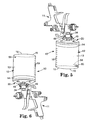
- That liquid supply assembly 10 (as is illustrated in Figures 3, 5 and 6) can be used to supply liquid for a conventional gravity fed liquid spraying device or spray gun 11 (e.g., the spray gun commercially designated NR 95 that is available from Sata, Farbspritztechnik GmbH & Co., Kornwestheim, Germany).
- a conventional gravity fed liquid spraying device or spray gun 11 e.g., the spray gun commercially designated NR 95 that is available from Sata, Farbspritztechnik GmbH & Co., Kornwestheim, Germany.
- the liquid supply assembly 10 includes a conventional paint mixing cup 12 of stiff polymeric material (e.g., the polyethylene mixing cups commercially available from PPG, Cleveland, Ohio, which can be obtained in 8 ounce or 240ml, or 16 ounce or 480ml, or 24 ounce or 720ml, or 32 ounce or 960 ml sizes).
- the paint mixing cup comprises a generally cylindrical side wall 13 having top and bottom ends 14 and 15, a bottom wall 16 extending across and closing the bottom end 15 of the side wall 13, and an outwardly projecting lip 18 around the top end 14 of the side wall 13.
- the top end 14 of the side wall 13 defines an opening into the cup 12.
- the side wall 13 bears indicia 19 indicating the levels to which two or three different liquids should be sequentially poured into the cup 12 through that opening to provide a predetermined ratio between those liquids, that indicia 19 being provided for a plurality of different ratios.
- the side wall 13 is sufficiently translucent to afford seeing the liquid level in the cup 12 through the side wall 13 which assists a person in adding liquids to the desired levels indicated by the indicia 19.
- the liquid supply assembly 10 also includes a first adapter 20, (see Figures 1, 2, and 3) preferably molded of polymeric material (e.g., polyethylene), having opposite inner and outer major surfaces 21 and 22.
- the first adapter 20 comprises a central generally cylindrical portion 24 having a through opening 26 and a transverse portion 28 including a peripheral part 30.
- the transverse portion 28 defines a groove 32 along its inner surface that is adapted for sealing engagement with the top end 14 and outwardly projecting lip 18 of the paint mixing cup 12.
- a second adapter 34 (see Figures 1, 2, 3, and4), also included in the liquid supply assembly 10, is preferably of metal (e.g., aluminum), has first and second spaced end portions 36 and 38, and has a through opening 40 extending through those end portions 36 and 38.
- the first end portion 36 of the second adapter 34 has internal threads 41 and six flatted wrench engageable surface portions 42 around its periphery, thereby being adapted to be releasably engaged with external threads on the inlet port of the gravity fed spray gun 11.
- the first adapter 20 and the second end portion 38 of the second adapter 34 have connector parts that are adapted for releasable liquid tight engagement with their through openings 26 and 40 in communication.
- Those connector parts include axially spaced radially outwardly projecting sealing rings 43 along the outer surface of the cylindrical portion 24, and a cylindrical inner surface 44 of the second adapter 34 that defines a cylindrical bore opening through the end of the second adapter 34 opposite the threads 41. That bore is adapted to receive the cylindrical portion 24 of the first adapter 20 in an engaged position with the sealing rings 43 in slightly compressed liquid tight engagement with the inner surface 44 defining the bore and with an end surface 46 on a collar 45 around the second end portion 38 of the second adapter 34 abutting a boss 47 in the first adapter 20 around the cylindrical portion 24.
- the collar 45 has major cylindrically concave recesses 48 along opposite sides of its periphery (see Figure 4) adapted to pass the distal ends of hook members 49 projecting from the transverse portion 28 of the first adapter 20 on opposite sides of the cylindrical portion 24 when the cylindrical portion 24 is pressed axially into the bore with the first and second adapters 20 and 34 in a first relative position at which the hook members 49 are aligned with the major recesses 48 in the collar 45.
- the first and second adapters 20 and 34 can then be rotated relative to each other to a second relative position to cause the resiliently flexible projecting hook members 49 to be deflected outwardly by, and to move around, cylindrically convex cam lobes 50 projecting radially outwardly on corresponding sides of the major recesses 48 until the projecting hook members 49 are positioned in minor cylindrically concave recesses 51 in the collar 45 at which opposed inwardly projecting lips 52 on the distal ends of the projecting hook members 49 are engaged over a surface 53 of the collar 45 adjacent the first end 36 of the second adapter 34.
- Lugs 54 projecting axially past the end surface 46 of the collar 45 are adapted to move between positions engaging sides of the boss 47 on the first adapter 20 when the cylindrical portion 24 is in its engaged position in the bore defined by the inner surface 44, thereby limiting relative movement between the adapters 20 and 34 to movement to and between those first and second relative positions.
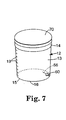
- the liquid supply assembly 10 further includes a tapered, pointed, removable pin 56 (e.g., a pin of the type sometimes called a "push pin") extending through a passageway 58 in the side wall 13 of the cup 12 adjacent its bottom wall 16 (see Figures 1 and 5).
- a tapered, pointed, removable pin 56 e.g., a pin of the type sometimes called a "push pin"
- the pin 56 can be manually pressed through the side wall 13 to form the passageway 58.
- the pin 56 can be removed so that the passageway 58 will provide vacuum relief for the cup 12 by then allowing air to enter the cup 12 through the passageway 58 above the liquid (e.g., paint) being supplied to the spray gun 11.
- the pin 56 may be positioned in the passageway 58 as is illustrated in Figure 5 to preclude liquid within the cup 12 from leaking through the passageway 58 when the cup is supported on its bottom wall 16.
- the combination 10 can also include a removable filter assembly 62 (see Figures 2 and 3) of a known commercially available type (e.g., the filter commercially designated "paint filter kit” that is commercially available from Standard Color, St. Paul, MN).
- the filter assembly 62 includes a stiff polymeric frame comprising a cylindrical outlet portion 64 having a cylindrical outer surface frictionally engaged within the inner surface defining the through opening 26 in the central portion 24, which outlet portion 64 has a through opening.
- the frame of the filter assembly 62 further includes an inlet portion 66 projecting from the inner surface 21 of the transverse portion 28 of the first adapter 20.
- the inlet portion 66 has four axially extending rectangular inlet passageways 67 spaced around its periphery that communicate with the through opening in the outlet portion 64, and includes a filter screen 68 extending across the inner ends of those inlet passageways 67.
- a method according to the present invention for providing a supply of mixed liquids for the gravity fed liquid spraying device 11 includes mixing the liquids in the mixing cup 12 using the indicia 19 to indicate the levels to which the liquids should be sequentially poured into the cup 12 to achieve the desired ratio between the liquids; engaging the peripheral part 30 of the first adapter 20 with the top end 14 of the mixing cup 12 containing the mixed liquids; engaging the first end 36 of the second adapter 34 with the inlet port of the liquid spraying device 11 (if this has not already been done); engaging the connector parts as described above (this being done with the mixing cup supported on its bottom wall and the spraying device inverted as illustrated in Figure 3); and positioning the spraying device 11 as illustrated in Figure 4 so that the bottom wall 16 of the mixing cup 12 is uppermost to feed the liquid in the mixing cup 12 to the spraying device 11 through the filter assembly 62 and the openings 26 and 40 in the adapters 20 and 34.
- That method can further include inserting the tapered pin 56 through the side wall 13 of the mixing cup 12 adjacent its bottom wall 16, and removing the tapered pin 56 from the side wall 13 after the spraying device 11 is positioned with the bottom wall 16 of the mixing cup 12 uppermost as illustrated in Figure 4 to feed the liquid in the mixing cup 12 to the spraying device.
- Such insertion of the tapered pin 56 provides the passageway 58 through the side wall 13 of the mixing cup 12 adjacent its bottom wall 16 so that air can flow into the cup 12 through the passageway 58 as the liquid is sprayed to restrict causing a vacuum in the mixing cup 12.
- the pin 56 can be inserted through the passageway 58 to restrict leakage of liquid through the passageway 58; the spraying device 11 can again be inverted to the position illustrated in Figure 3, the connector parts can be disconnected, the first adapter 20 can be removed from the top end 14 of the mixing cup 12 containing the remaining liquid; a conventional cover 70 (see Figure 7) can be applied to the top end 14 of the mixing cup 12, and the remaining liquid can be stored for future use in the covered mixing cup 12.
- the inexpensive first adapter 20 and the filter assembly 52 can then be disposed of so that cleanup of the liquid supply assembly 10 only requires cleaning the second adapter 34, which is cleaned with the spray gun 11.
Description
Claims (6)
- A liquid supply assembly (10) for use on a gravity fed liquid spraying device (11), said supply assembly (10) comprising:characterised by said assembly further including a tapered removable pin (56) extending through said side wall (13) of said mixing cup (12) adjacent said bottom wall (16), said pin (56) having been pressed through the side wall (13) to form a passageway (58) through the side wall (13), being positioned in the passageway (58) to restrict any liquid in the mixing cup (12) from moving through the passageway (58), being removable from the passageway (58) to allow air to move through the passageway (58) into the mixing cup (12) adjacent said bottom wall (16), and after such removal being again positionable in the passageway (58) to again restrict any liquid in the mixing cup (12) from moving through the passageway (58).a mixing cup (12) of stiff polymeric material comprising a side wall (13) having top and bottom ends (14, 15), and a bottom wall (16) extending across and closing the bottom end (15) of said side wall (13), said top end (14) of said side wall (13) defining an opening into said cup (12), and said side wall (13) bearing indicia (19) indicating the levels to which a plurality of different liquids can be sequentially poured into the cup (12) to achieve a predetermined ratio between the liquids;an adapter assembly (20, 34) having an inner major surface and an opposite outer major surface, said adapter assembly (20, 34) comprising a transverse portion (28) including a peripheral part (30) defining a groove (32) along said inner surface receiving said top end (14) of said mixing cup (12) in sealing engagement with said peripheral part (30), and a first end portion (36) opposite said transverse portion (28) adapted to releasably engage an inlet port of the gravity fed liquid spraying device (11), said inner surface defining a through opening (26, 40) extending through said transverse portion (28) and said first end portion (36);
- A liquid supply assembly (10) according to claim 1, said adapter assembly comprising:said second end portion (38) of said second adapter (34) and said central portion (24) of said first adapter (20) having connector parts in manually releasable liquid tight engagement between said adapters (20, 34) with said through openings (26, 40) in communication.a first adapter (20) of polymeric material having said inner major surface (21) and said opposite outer major surface (22), said first adapter (20) comprising a central portion (24) having a through opening (26) and said transverse portion (28); anda second adapter (34) having said first end portion (36) and a second end portion (38) spaced from said first end portion (36), said second adapter (34) having a through opening (40) extending through said first and second end portions (36, 38), said first end portion. (36) being adapted to releasably engage an inlet port of the gravity fed liquid spraying device (11);
- A liquid supply assembly (10) according to claim 2 further including a removable filter assembly (62) including a frame comprising an outlet portion (64) engaged across said through opening (26) in said central portion (24) and having a through opening, said frame further including an inlet portion (66) projecting from the inner surface (21) of said first adapter (20) and having inlet passageways (67) communicating with said through opening in said outlet portion (64), and a filter screen (68) extending across said inlet passageways (67).
- A method for providing a supply of mixed liquids for a gravity fed liquid spraying device (11), said method comprising the steps of:characterised by inserting a tapered pin (56) through the side wall (13) of the mixing cup (12) adjacent said bottom wall (16) to form a passageway (58) through the sidewall, said pin (56) being positioned in the passageway (58) to restrict any liquid in the mixing cup (12) from moving through the passageway (58);providing a mixing cup (12) of stiff polymeric material comprising a side wall (13) having top and bottom ends (14, 15), and a bottom wall (16) extending across and closing the bottom end (15) of said side wall (13), said top end (14) of said side wall (13) defining an opening into said cup(12), and said side wall (13) bearing indicia (19) indicating the levels to which the liquids can be sequentially poured into the cup (12) to achieve a predetermined ratio between the liquids;providing adapters including a first adapter (20) having an inner major surface (21) and an opposite outer major surface (22), said first adapter (20) comprising a central portion (24) having a through opening (26) and a transverse portion (28) including a peripheral part (30) defining a groove (32) along said inner major surface (21) adapted to receive the top end (14) of said mixing cup (12) in sealing engagement with said peripheral part (30), and a second adapter (34) having a first end portion (36) and a second end portion (38) spaced from said first end portion (36), said second adapter (34) having a through opening (40) extending through said first and second end portions (36, 38), said first end portion (36) being adapted to engage an inlet port of the gravity fed liquid spraying device ( I I ); said second end portion (38) of said second adapter (34) and said central portion (24) of said first adapter (20) having connector parts adapted for manually releasable liquid tight engagement between said adapters (20, 34) with said through openings (26, 40) in communication;mixing the liquids in the mixing cup (12) using the indicia (19) to indicate the levels to which the liquids are poured into the cup (12) to achieve a predetermined ratio between the liquids;engaging the first adapter (20) with the top end (14) of the side wall (13) of the mixing cup (12) containing the mixed liquids;
engaging the first end portion (36) of the second adapter (34) with an inlet port of the gravity fed liquid spraying device (11);
manually engaging the connector parts;
positioning the spraying device (11) so that the bottom wall (16) of the mixing cup (12) is uppermost to feed the liquid in the mixing cup (12) to the spraying device (11) through the openings in the adapters (20, 34); and
removing the tapered pin (56) from the side wall (13) during the positioning step to allow air to move through the passageway (58) into the mixing cup (12) adjacent said bottom wall (16). - A method according to claim 4 further including the steps, used when liquid remains in the mixing cup (12) after use of the liquid spraying device, of reinserting the pin (56) through the passageway (58) to restrict leakage of liquid through the passageway (58), manually separating the connector parts to separate the adapters (20, 34), removing the first adapter (20) from the top end of the mixing cup (12) containing the remaining liquid, applying a cover to the top end of the mixing cup (12), and storing the remaining liquid in the covered mixing cup (12).
- A method according to claim 4 wherein said first adapter (20) is of polymeric material and said method further includes the step of manually separating the connector parts to separate the adapters (20, 34), removing the first adapter (20) from the top end of the mixing cup (12), and disposing of the first adapter (20).
Priority Applications (3)
| Application Number | Priority Date | Filing Date | Title |
|---|---|---|---|
| DE20023419U DE20023419U1 (en) | 1999-08-16 | 2000-08-11 | Adapter for paint mixing container for connecting it to a gravity-fed paint spray gun |
| EP03013327A EP1366823B1 (en) | 1999-08-16 | 2000-08-11 | Connection between mixing cup and spray gun |
| US10/453,413 US7090148B2 (en) | 1999-08-16 | 2003-06-03 | Mixing cup adapting assembly |
Applications Claiming Priority (3)
| Application Number | Priority Date | Filing Date | Title |
|---|---|---|---|
| US09/374,794 US6536687B1 (en) | 1999-08-16 | 1999-08-16 | Mixing cup adapting assembly |
| US374794 | 1999-08-16 | ||
| PCT/US2000/022262 WO2001012337A1 (en) | 1999-08-16 | 2000-08-11 | Colour mixing cup adapting assembly for connecting the cup to a gravity feed paint sprayer |
Related Child Applications (1)
| Application Number | Title | Priority Date | Filing Date |
|---|---|---|---|
| EP03013327A Division EP1366823B1 (en) | 1999-08-16 | 2000-08-11 | Connection between mixing cup and spray gun |
Publications (2)
| Publication Number | Publication Date |
|---|---|
| EP1210181A1 EP1210181A1 (en) | 2002-06-05 |
| EP1210181B1 true EP1210181B1 (en) | 2003-10-29 |
Family
ID=23478221
Family Applications (2)
| Application Number | Title | Priority Date | Filing Date |
|---|---|---|---|
| EP03013327A Expired - Lifetime EP1366823B1 (en) | 1999-08-16 | 2000-08-11 | Connection between mixing cup and spray gun |
| EP00957434A Expired - Lifetime EP1210181B1 (en) | 1999-08-16 | 2000-08-11 | Colour mixing cup adapting assembly for connecting the cup to a gravity feed paint sprayer |
Family Applications Before (1)
| Application Number | Title | Priority Date | Filing Date |
|---|---|---|---|
| EP03013327A Expired - Lifetime EP1366823B1 (en) | 1999-08-16 | 2000-08-11 | Connection between mixing cup and spray gun |
Country Status (8)
| Country | Link |
|---|---|
| US (3) | US6536687B1 (en) |
| EP (2) | EP1366823B1 (en) |
| JP (1) | JP5068908B2 (en) |
| KR (1) | KR100713728B1 (en) |
| CA (1) | CA2380462A1 (en) |
| DE (4) | DE20023419U1 (en) |
| ES (2) | ES2333854T3 (en) |
| WO (1) | WO2001012337A1 (en) |
Cited By (12)
| Publication number | Priority date | Publication date | Assignee | Title |
|---|---|---|---|---|
| US7086549B2 (en) | 2004-01-16 | 2006-08-08 | Illinois Tool Works Inc. | Fluid supply assembly |
| US7165732B2 (en) | 2004-01-16 | 2007-01-23 | Illinois Tool Works Inc. | Adapter assembly for a fluid supply assembly |
| US7665672B2 (en) | 2004-01-16 | 2010-02-23 | Illinois Tool Works Inc. | Antistatic paint cup |
| US7757972B2 (en) | 2004-06-03 | 2010-07-20 | Illinois Tool Works Inc. | Conversion adapter for a fluid supply assembly |
| US7766250B2 (en) | 2004-06-01 | 2010-08-03 | Illinois Tool Works Inc. | Antistatic paint cup |
| US7874323B2 (en) | 2004-06-10 | 2011-01-25 | Illinois Tool Works, Inc. | Fluid supply assembly |
| US8033413B2 (en) | 2006-06-20 | 2011-10-11 | Saint-Gobain Abrastives, Inc. | Liquid supply assembly |
| US8127963B2 (en) | 2004-12-16 | 2012-03-06 | Saint-Gobain Abrasives, Inc. | Liquid container system for a spray gun |
| US8944351B2 (en) | 2011-05-06 | 2015-02-03 | Saint-Gobain Abrasives, Inc. | Paint cup assembly with an outlet valve |
| US9586220B2 (en) | 2011-06-30 | 2017-03-07 | Saint-Gobain Abrasives, Inc. | Paint cup assembly |
| US10882064B2 (en) | 2011-12-30 | 2021-01-05 | Saint-Gobain Abrasives, Inc./Saint-Gobain Abrasifs | Convertible paint cup assembly with air inlet valve |
| US11040360B2 (en) | 2006-06-20 | 2021-06-22 | Saint-Gobain Abrasives, Inc. | Liquid supply assembly |
Families Citing this family (147)
| Publication number | Priority date | Publication date | Assignee | Title |
|---|---|---|---|---|
| US6820824B1 (en) | 1998-01-14 | 2004-11-23 | 3M Innovative Properties Company | Apparatus for spraying liquids, disposable containers and liners suitable for use therewith |
| US6536687B1 (en) * | 1999-08-16 | 2003-03-25 | 3M Innovative Properties Company | Mixing cup adapting assembly |
| WO2002062482A2 (en) * | 2000-11-02 | 2002-08-15 | Gambro, Inc. | Fluid separation devices, systems and methods |
| US7143960B2 (en) * | 2001-03-14 | 2006-12-05 | 3M Innovative Properties Company | Liquid sample reservoir suitable for use with a spraying apparatus |
| US7188785B2 (en) * | 2001-04-24 | 2007-03-13 | 3M Innovative Properties Company | Reservoir with refill inlet for hand-held spray guns |
| US6588681B2 (en) * | 2001-07-09 | 2003-07-08 | 3M Innovative Properties Company | Liquid supply assembly |
| US20040217201A1 (en) * | 2001-11-14 | 2004-11-04 | Martin Ruda | Spray gun container |
| DE10205831A1 (en) * | 2002-02-13 | 2003-08-28 | Sata Farbspritztechnik | Spray Gun |
| US6752179B1 (en) | 2002-03-28 | 2004-06-22 | 3M Innovative Properties Company | Small liquid supply assembly |
| GB0210446D0 (en) * | 2002-05-08 | 2002-06-12 | 3M Innovative Properties Co | Conformable pouch reservoir for spray gun |
| GB0210448D0 (en) * | 2002-05-08 | 2002-06-12 | 3M Innovative Properties Co | Valve closure for spray gun reservoir |
| US7017834B2 (en) * | 2002-08-15 | 2006-03-28 | Santa Cruz Cathy D | Liquid storage, dispensing, mixing, application, system and method of use |
| GB0224698D0 (en) | 2002-10-24 | 2002-12-04 | 3M Innovative Properties Co | Easy clean spray gun |
| US6953155B2 (en) | 2002-10-24 | 2005-10-11 | 3M Innovative Properties Company | Pressure assisted liquid supply assembly |
| DE10315426A1 (en) * | 2002-12-10 | 2004-06-24 | Martin Ruda | Single-walled spray gun container for painting has paint-receiving section accessible via two main apertures and with supplementary access to receiving section |
| DE20320781U1 (en) * | 2002-12-10 | 2005-05-04 | Ruda, Martin | Single-walled spray gun cup |
| GB0229399D0 (en) * | 2002-12-18 | 2003-01-22 | 3M Innovative Properties Co | Drop-in filter for spray gun reservoir |
| US7832567B2 (en) * | 2002-12-18 | 2010-11-16 | 3M Innovative Properties Company | Drop-in filter for spray gun reservoir |
| US7845582B2 (en) * | 2002-12-18 | 2010-12-07 | 3M Innovative Properties Company | Spray gun reservoir with oversize, fast-fill opening |
| GB0307902D0 (en) * | 2003-04-05 | 2003-05-14 | 3M Innovative Properties Co | Spray gun with rotatable reservoir |
| US6698670B1 (en) * | 2003-06-10 | 2004-03-02 | Illinois Tool Works Inc. | Friction fit paint cup connection |
| US6945429B2 (en) * | 2003-06-10 | 2005-09-20 | Illinois Tool Works Inc. | Disposable paint cup attachment system for gravity-feed paint sprayer |
| FR2859118B1 (en) * | 2003-08-26 | 2007-03-09 | Michel Camilleri | DISPOSABLE BUCKET TO BE MOUNTED ON A GUN FOR THE PREPARATION, APPLICATION AND PRESERVATION OF A PAINT |
| US7083119B2 (en) * | 2003-09-25 | 2006-08-01 | 3M Innovative Properties Company | Security clip for spray gun connector |
| CA2448110A1 (en) * | 2003-11-05 | 2005-05-05 | Simon Yechouron | Paint gun accessory |
| DE102004018140A1 (en) * | 2003-12-09 | 2005-07-21 | Martin Ruda | Spray gun cup with a connection device and method for painting |
| CA2455182A1 (en) * | 2004-01-14 | 2005-07-14 | Charles Harland | Spray gun receptacle |
| US7380680B2 (en) * | 2004-01-16 | 2008-06-03 | Illinois Tool Works Inc. | Fluid supply assembly |
| DE102004003439B4 (en) * | 2004-01-22 | 2022-02-03 | Sata Gmbh & Co. Kg | Paint cup system for a paint spray gun |
| DE202004021702U1 (en) | 2004-01-22 | 2010-05-20 | Sata Gmbh & Co. Kg | Gravity cup for a paint spray gun |
| US20050242107A1 (en) * | 2004-04-29 | 2005-11-03 | Kosmyna Michael J | Part dispenser assembly |
| US20050258271A1 (en) * | 2004-05-18 | 2005-11-24 | Kosmyna Michael J | Disposable paint cup |
| US7354074B2 (en) * | 2004-06-03 | 2008-04-08 | Illinois Tool Works Inc. | Adapter assembly for a fluid supply assembly |
| ES2273198T3 (en) | 2004-07-02 | 2007-05-01 | Flexi-Cup | FLEXIBLE CONTAINER SUITABLE FOR PAINTING. |
| US7798711B2 (en) * | 2004-07-27 | 2010-09-21 | Cdf Corporation | Flexible liner for FIBC or bag-in-box container systems |
| GB0422388D0 (en) | 2004-10-08 | 2004-11-10 | 3M Innovative Properties Co | Locking ring for spray gun connector |
| GB0423243D0 (en) * | 2004-10-20 | 2004-11-24 | Dunne Stephen T | Liquid dispensing means |
| US20060102550A1 (en) * | 2004-11-18 | 2006-05-18 | Joseph Stephen C P | Liquid supply and filter assembly |
| US7175110B2 (en) * | 2004-12-21 | 2007-02-13 | Anest Iwata Corporation | Manual spray gun and associated disposable cup |
| DE102005020197B4 (en) * | 2005-01-19 | 2014-03-20 | Martin Ruda | Mixing cup with a scale for preparing paint compositions and method for producing such a mixing cup |
| EP1844302A2 (en) * | 2005-01-31 | 2007-10-17 | Illinois Tool Works Inc. | Fluid supply assembly with measuring guide |
| US7410106B2 (en) * | 2005-02-08 | 2008-08-12 | 3M Innovative Properties Company | Pressurized liquid supply assembly |
| NL1028575C2 (en) | 2005-03-18 | 2006-09-20 | Emm Productions B V | Disposable cup for a paint sprayer and paint sprayer fitted with it. |
| US7036752B1 (en) * | 2005-06-20 | 2006-05-02 | Shin Kuei Hsiang | Connection of cup and paint sprayer |
| US20070076988A1 (en) * | 2005-09-26 | 2007-04-05 | Joseph Sullivan | Flexible Liner with Fitting on Gusseted Side |
| US20070095943A1 (en) | 2005-10-28 | 2007-05-03 | Turnbull William N | Liquid reservoir, and kit, spray assembly and method using same |
| DE502006004167D1 (en) * | 2006-02-11 | 2009-08-20 | Wagner Gmbh J | Spray gun with adapted reservoir |
| US8075188B2 (en) * | 2006-02-24 | 2011-12-13 | Cdf Corporation | Flexible liner for FIBC or bag-in-box container systems with improved flex crack resistance |
| US20070205305A1 (en) * | 2006-03-03 | 2007-09-06 | Rbl Products, Inc. | Paint spray system |
| US8182152B2 (en) | 2006-03-28 | 2012-05-22 | Cdf Corporation | Flexible liner for FIBC or bag-in-box container systems with improved tensile strength |
| WO2007137257A2 (en) | 2006-05-22 | 2007-11-29 | 3M Innovative Properties Company | System and method for preparing samples |
| US20070269341A1 (en) * | 2006-05-22 | 2007-11-22 | 3M Innovative Properties Company | Sampling assembly and method of preparing samples |
| DE502007000825D1 (en) * | 2006-12-05 | 2009-07-16 | Sata Gmbh & Co Kg | Ventilation for the gravity cup of a paint spray gun |
| US9016555B2 (en) | 2007-04-03 | 2015-04-28 | Cdf Corporation | Flexible liner and bag-in-box container systems |
| US20080251609A1 (en) * | 2007-04-12 | 2008-10-16 | Ting Chin-Ming | Apparatus Used in Combination with Paint Delivery hopper |
| DE202007011604U1 (en) * | 2007-08-18 | 2009-01-02 | Sata Gmbh & Co. Kg | Connecting part for connecting a material supply device to a spray gun |
| EP2217377B1 (en) | 2007-11-20 | 2013-09-18 | 3M Innovative Properties Company | Sample preparation for environmental sampling |
| WO2009067518A1 (en) | 2007-11-20 | 2009-05-28 | 3M Innovative Properties Company | Sample preparation container and method |
| EP2217378B1 (en) | 2007-11-20 | 2013-02-13 | 3M Innovative Properties Company | Sample preparation container and method |
| CN101909755B (en) | 2007-11-20 | 2013-09-18 | 3M创新有限公司 | Sample preparation container and method |
| WO2009090273A1 (en) * | 2008-01-16 | 2009-07-23 | Boss Auto Import, S.A. | Improved disposable double-wall cup having a flexible inner surface and cover for spray guns |
| JP2011519307A (en) | 2008-03-12 | 2011-07-07 | ジェフリー ディー フォックス | Disposable spray gun cartridge |
| US7815132B2 (en) * | 2008-08-12 | 2010-10-19 | Illinois Tool Works Inc. | Method for preventing voltage from escaping fluid interface for water base gravity feed applicators |
| US9399215B2 (en) | 2012-04-13 | 2016-07-26 | Bio-Rad Laboratories, Inc. | Sample holder with a well having a wicking promoter |
| DE202008014389U1 (en) | 2008-10-29 | 2010-04-08 | Sata Gmbh & Co. Kg | Gravity cup for a paint spray gun |
| KR101729793B1 (en) | 2009-01-26 | 2017-04-24 | 쓰리엠 이노베이티브 프로퍼티즈 컴파니 | Liquid spray gun, spray gun platform, and spray head assembly |
| TW201036707A (en) * | 2009-04-01 | 2010-10-16 | Victor Air Tools Co Ltd | Feeding structure of spray device |
| DE102009032399A1 (en) | 2009-07-08 | 2011-01-13 | Sata Gmbh & Co. Kg | Spray Gun |
| DE202010009104U1 (en) * | 2009-10-23 | 2011-03-10 | Sata Gmbh & Co. Kg | Paint container, in particular for paint spray guns |
| US9120608B2 (en) * | 2009-11-17 | 2015-09-01 | Cdf Corporation | Sustainable packaging system for shipping liquid or viscous products |
| US8567660B2 (en) * | 2009-11-17 | 2013-10-29 | Cdf Corporation | Sustainable packaging system for shipping liquid or viscous products |
| US9079201B2 (en) * | 2010-01-22 | 2015-07-14 | Finishing Brands Holdings Inc. | Liquid supply system for a gravity feed spray device |
| DE202010007355U1 (en) | 2010-05-28 | 2011-10-20 | Sata Gmbh & Co. Kg | Nozzle head for a spraying device |
| US20120000992A1 (en) * | 2010-07-01 | 2012-01-05 | Hsien-Chao Shih | Paint cup structure of paintball gun |
| US10286414B2 (en) | 2010-07-12 | 2019-05-14 | Carlisle Fluid Technologies, Inc. | Liquid supply container for a spray coating device |
| MX2013005546A (en) | 2010-11-16 | 2014-05-27 | Cdf Corp | Secondary packaging system for pre-packaged products. |
| US9333519B2 (en) | 2010-12-02 | 2016-05-10 | Sata Gmbh & Co. Kg | Spray gun and accessories |
| CN103370139B (en) | 2011-02-09 | 2017-09-05 | 3M创新有限公司 | Nozzle head and nozzle component for liquid spray gun |
| US9103711B2 (en) | 2011-04-14 | 2015-08-11 | Dennis Farhat | Beam scale for proportioning a first component and a second component |
| RU2601337C2 (en) | 2011-06-30 | 2016-11-10 | САТА ГмбХ унд Ко. КГ | Paint spray gun with possibility of easy cleaning, accessory for paint spray gun and method of their assembly and disassembly |
| BR112014001936A2 (en) | 2011-07-28 | 2017-02-21 | 3M Innovative Properties Co | sprinkler head assembly with integrated nozzle / air cap for a liquid spray gun |
| US9802211B2 (en) | 2011-10-12 | 2017-10-31 | 3M Innovative Properties Company | Spray head assemblies for liquid spray guns |
| EP2771127B1 (en) | 2011-10-27 | 2017-07-12 | Graco Minnesota Inc. | Sprayer fluid supply with collapsible liner |
| WO2013134182A1 (en) | 2012-03-06 | 2013-09-12 | 3M Innovative Properties Company | Spray gun having internal boost passageway |
| US11167298B2 (en) | 2012-03-23 | 2021-11-09 | 3M Innovative Properties Company | Spray gun barrel with inseparable nozzle |
| EP2877293B1 (en) | 2012-07-27 | 2020-03-11 | 3M Innovative Properties Company | Vent assembly and reservoirs including the same |
| US9352343B2 (en) | 2013-01-22 | 2016-05-31 | Carlisle Fluid Technologies, Inc. | Liquid supply system for a gravity feed spray device |
| RU2015141120A (en) * | 2013-03-29 | 2017-05-10 | 3М Инновейтив Пропертиз Компани | Vented container assembly |
| AU2014290641B2 (en) | 2013-07-15 | 2017-07-06 | 3M Innovative Properties Company | Air caps with face geometry inserts for liquid spray guns |
| CA155474S (en) | 2013-09-27 | 2015-08-27 | Sata Gmbh & Co Kg | Spray gun |
| JP6002957B2 (en) * | 2013-10-29 | 2016-10-05 | 兵神装備株式会社 | Discharge system |
| ES2848277T3 (en) | 2013-12-05 | 2021-08-06 | 3M Innovative Properties Co | Container for spraying device |
| DE202013105779U1 (en) | 2013-12-18 | 2015-03-19 | Sata Gmbh & Co. Kg | Air nozzle termination for a paint spray gun |
| CN105289870B (en) | 2014-07-31 | 2019-09-24 | 萨塔有限两合公司 | Manufacturing method, spray gun, gun body and the lid of spray gun |
| CA159961S (en) | 2014-07-31 | 2015-07-17 | Sata Gmbh & Co Kg | Spray gun |
| USD758537S1 (en) | 2014-07-31 | 2016-06-07 | Sata Gmbh & Co. Kg | Paint spray gun rear portion |
| USD768820S1 (en) | 2014-09-03 | 2016-10-11 | Sata Gmbh & Co. Kg | Paint spray gun with pattern |
| US9796492B2 (en) | 2015-03-12 | 2017-10-24 | Graco Minnesota Inc. | Manual check valve for priming a collapsible fluid liner for a sprayer |
| US20180051313A1 (en) | 2015-03-19 | 2018-02-22 | 3M Innovative Properties Company | Methods, devices, and kits for detecting microorganisms in a fluid sample |
| DE102015006484A1 (en) | 2015-05-22 | 2016-11-24 | Sata Gmbh & Co. Kg | Nozzle arrangement for a spray gun, in particular paint spray gun and spray gun, in particular paint spray gun |
| CN107847956B (en) | 2015-07-08 | 2021-08-10 | 3M创新有限公司 | Spray gun cup, receiver and method of use |
| EP3135385B2 (en) | 2015-08-25 | 2022-02-09 | Andreas Massold | Lid for a container for liquids for a spray gun |
| DE102015016474A1 (en) | 2015-12-21 | 2017-06-22 | Sata Gmbh & Co. Kg | Air cap and nozzle assembly for a spray gun and spray gun |
| CA3011425A1 (en) * | 2016-01-15 | 2017-07-20 | 3M Innovative Properties Company | Modular spray gun lid assemblies and methods of design and use |
| EP3842154A1 (en) | 2016-01-15 | 2021-06-30 | 3M Innovative Properties Company | Connector system for hand-held spray guns |
| US10689165B2 (en) * | 2016-01-15 | 2020-06-23 | 3M Innovative Properties Company | Reservoir systems for hand-held spray guns and methods of use |
| AU2017207358B2 (en) * | 2016-01-15 | 2019-10-31 | 3M Innovative Properties Company | Button-lock fluid connector for hand-held spray guns |
| ES2949320T3 (en) | 2016-01-15 | 2023-09-27 | 3M Innovative Properties Company | Reservoirs, spray gun receptacles and methods of use |
| AU2017207353B2 (en) | 2016-01-15 | 2019-10-31 | 3M Innovative Properties Company | Spray gun cups, receptacles, lids, and methods of use |
| WO2017123714A1 (en) | 2016-01-15 | 2017-07-20 | 3M Innovative Properties Company | Wide-mouthed fluid connector for hand-held spray guns |
| CN205966208U (en) | 2016-08-19 | 2017-02-22 | 萨塔有限两合公司 | Hood subassembly and spray gun |
| CN205995666U (en) | 2016-08-19 | 2017-03-08 | 萨塔有限两合公司 | Spray gun and its trigger |
| CN110062663B (en) | 2016-12-06 | 2022-02-22 | 3M创新有限公司 | Spray gun and nozzle assembly attachment |
| AU2017372935B2 (en) | 2016-12-06 | 2020-04-16 | 3M Innovative Properties Company | Spray gun air cap with retention means |
| USD810864S1 (en) * | 2016-12-12 | 2018-02-20 | 3M Innovative Properties Company | Spray gun liquid containment device |
| USD810867S1 (en) * | 2016-12-12 | 2018-02-20 | 3M Innovative Properties Company | Spray gun liquid containment device |
| USD810235S1 (en) * | 2016-12-12 | 2018-02-13 | 3M Innovative Properties Company | Spray gun liquid containment device |
| USD815248S1 (en) * | 2016-12-12 | 2018-04-10 | 3M Innovative Properties Company | Spray gun liquid containment device |
| USD810866S1 (en) * | 2016-12-12 | 2018-02-20 | 3M Innovative Properties Company | Spray gun liquid containment device |
| USD810862S1 (en) * | 2016-12-12 | 2018-02-20 | 3M Innovative Properties Company | Spray gun liquid containment device |
| USD813985S1 (en) * | 2016-12-12 | 2018-03-27 | 3M Innovative Properties Company | Spray gun liquid containment device |
| USD817443S1 (en) * | 2016-12-12 | 2018-05-08 | 3M Innovative Properties Company | Spray gun liquid containment device |
| USD810868S1 (en) * | 2016-12-12 | 2018-02-20 | 3M Innovative Properties Company | Spray gun liquid containment device |
| US11666934B2 (en) | 2016-12-12 | 2023-06-06 | 3M Innovative Properties Company | Spray gun and nozzle assembly attachment |
| EP3551337A1 (en) | 2016-12-12 | 2019-10-16 | 3M Innovative Properties Company | Spray gun and nozzle assembly attachment |
| USD810869S1 (en) * | 2016-12-12 | 2018-02-20 | 3M Innovative Properties Company | Spray gun liquid containment device |
| USD810865S1 (en) * | 2016-12-12 | 2018-02-20 | 3M Innovative Properties Company | Spray gun liquid containment device |
| USD810863S1 (en) * | 2016-12-12 | 2018-02-20 | 3M Innovative Properties Company | Spray gun liquid containment device |
| CN110114148A (en) | 2016-12-12 | 2019-08-09 | 3M创新有限公司 | Spray gun and nozzle assembly attachment |
| WO2018157066A1 (en) | 2017-02-27 | 2018-08-30 | 3M Innovative Properties Company | Air guide for coating fluid dispensing gun |
| CN110891694A (en) | 2017-07-14 | 2020-03-17 | 3M创新有限公司 | Fluid delivery assembly for spray gun |
| US11478817B2 (en) * | 2018-06-21 | 2022-10-25 | Silgan Dispensing Systems Corporation | Dispensing assembly including an additive mixing device |
| DE102018118737A1 (en) | 2018-08-01 | 2020-02-06 | Sata Gmbh & Co. Kg | Nozzle for a spray gun, nozzle set for a spray gun, spray guns and method for producing a nozzle for a spray gun |
| DE102018118738A1 (en) | 2018-08-01 | 2020-02-06 | Sata Gmbh & Co. Kg | Base body for a spray gun, spray guns, spray gun set, method for producing a base body for a spray gun and method for converting a spray gun |
| US11826771B2 (en) | 2018-08-01 | 2023-11-28 | Sata Gmbh & Co. Kg | Set of nozzles for a spray gun, spray gun system, method for embodying a nozzle module, method for selecting a nozzle module from a set of nozzles for a paint job, selection system and computer program product |
| CN113195107A (en) * | 2018-12-12 | 2021-07-30 | 3M创新有限公司 | Liquid spray gun, connector ring, liquid spray device and adapter system |
| EP3902634A1 (en) | 2018-12-27 | 2021-11-03 | 3M Innovative Properties Company | Fluid delivery assembly for a spraying apparatus |
| CN115739435A (en) | 2019-05-31 | 2023-03-07 | 固瑞克明尼苏达有限公司 | Hand-held fluid sprayer |
| USD916232S1 (en) * | 2019-06-04 | 2021-04-13 | Qingdao Hanbo Plastic Technology Co., Ltd. | Lid for spray gun |
| USD916231S1 (en) * | 2019-06-04 | 2021-04-13 | Qingdao Hanbo Plastic Technology Co., Ltd. | Lid for spray gun |
| EP4058207A1 (en) | 2019-11-11 | 2022-09-21 | 3M Innovative Properties Company | Vent assemblies |
| CN211660579U (en) | 2019-11-13 | 2020-10-13 | 创科无线普通合伙 | Pressure cleaning machine |
| USD971729S1 (en) | 2020-03-12 | 2022-12-06 | 3M Innovative Properties Company | Container lid |
| JP2023519294A (en) | 2020-03-27 | 2023-05-10 | スリーエム イノベイティブ プロパティズ カンパニー | spray gun converter |
| USD952097S1 (en) * | 2020-07-14 | 2022-05-17 | Yuyao Yufeng Scutcheon Plastic Factory | Paint spraying pot lid |
| USD1014702S1 (en) * | 2021-04-14 | 2024-02-13 | 3M Innovative Properties Company | Securement for paint dispensing system |
| AU2022299015A1 (en) * | 2021-06-25 | 2024-01-18 | W.M. Barr & Company, Inc. | Automotive spray gun bottle and adapter |
Family Cites Families (32)
| Publication number | Priority date | Publication date | Assignee | Title |
|---|---|---|---|---|
| US856361A (en) * | 1906-05-25 | 1907-06-11 | Gustave L Neiburg | Apparatus for electrochemically and mechanically purifying liquids. |
| DE210449C (en) * | 1907-02-22 | 1909-05-29 | ||
| GB191223826A (en) * | 1912-10-18 | 1913-06-12 | Robert Fader | Improvements in Airbrushes. |
| US1476668A (en) * | 1922-04-04 | 1923-12-04 | Sr James B Agnew | Oil can |
| US1476666A (en) | 1923-01-03 | 1923-12-04 | Williams John Thomas | Stile-horning machine |
| US2263843A (en) * | 1937-09-03 | 1941-11-25 | Binks Mfg Co | Container connecting means for spraying devices |
| BE491243A (en) * | 1948-09-21 | |||
| BE517923A (en) * | 1952-02-28 | |||
| US2801880A (en) * | 1956-04-03 | 1957-08-06 | Rienecker Fred | Hopper spray gun |
| US2901182A (en) | 1957-08-07 | 1959-08-25 | Donaldson Co Inc | Engine operated insecticide sprayer |
| US3236459A (en) * | 1963-12-16 | 1966-02-22 | Thomas P Mcritchie | Apparatus for spraying materials |
| JPS49111487U (en) * | 1972-11-08 | 1974-09-24 | ||
| DE2412743A1 (en) * | 1974-03-16 | 1975-09-25 | Daimler Benz Ag | Constant mixture ratio device - for spraying two-component lacquer filler, etc |
| US4411397A (en) | 1978-07-18 | 1983-10-25 | Bell & Howell Company | Bidirectional tape drive systems |
| CH653574A5 (en) * | 1983-01-11 | 1986-01-15 | Ehrensperger C Ag | Device for spraying flowable and liquid materials |
| DE3346165A1 (en) * | 1983-12-21 | 1985-07-11 | Heinrich Ihmels + Sohn, 2905 Edewecht | SPRAYER INSERT FOR SPRAY GUNS |
| US4773569A (en) * | 1984-10-22 | 1988-09-27 | Unro Teknik Ab | Dispenser for pasty matter |
| JPS61194882U (en) * | 1985-05-28 | 1986-12-04 | ||
| DE3526819A1 (en) * | 1985-07-26 | 1987-02-12 | Bramlage Gmbh | Dispenser for pasty substances |
| US5069389A (en) * | 1988-10-31 | 1991-12-03 | Constantine Bitsakos | Adapter for an air spray paint gun |
| US4946075A (en) * | 1989-06-29 | 1990-08-07 | Unro Teknik Ab | Device for dispensing flowing substances |
| US4993639A (en) | 1989-10-04 | 1991-02-19 | Mitsuo Hata | Mist sprayer |
| DE4129397C1 (en) * | 1991-09-04 | 1993-03-11 | Rasmussen Gmbh, 6457 Maintal, De | |
| US5271683A (en) * | 1992-07-29 | 1993-12-21 | Wagner Spray Tech Corporation | Roller arm guide for hand-held paint gun |
| DE69509373T2 (en) * | 1994-02-18 | 1999-08-26 | Itw Ltd | Spray gun with permanently attached spray head |
| US5524795A (en) * | 1994-04-14 | 1996-06-11 | Lee; Gary K. | Dispensing unit for a threaded neck bottle |
| CA2143277C (en) * | 1994-04-19 | 2000-05-16 | Michael J. Kosmyna | Hand held paint spray gun with top mounted paint cup |
| EP2090372B1 (en) | 1997-01-24 | 2014-06-18 | 3M Company | Apparatus for spraying liquids, and disposable containers and liners suitable for use therewith |
| US6165159A (en) * | 1997-08-27 | 2000-12-26 | Blanton; Karen J. | Gas vent for ostomy bags |
| FR2783440B1 (en) * | 1998-09-18 | 2001-02-23 | Michel Camilleri | DISPOSABLE CYLINDRICAL BUCKET FOR PREPARING OR MIXING PAINTS FOR USE AS A PAINT GUN BUCKET |
| US6302445B1 (en) * | 1998-09-22 | 2001-10-16 | Certainteed Corporation | Irrigation pipe system |
| US6536687B1 (en) | 1999-08-16 | 2003-03-25 | 3M Innovative Properties Company | Mixing cup adapting assembly |
-
1999
- 1999-08-16 US US09/374,794 patent/US6536687B1/en not_active Expired - Lifetime
-
2000
- 2000-08-11 DE DE20023419U patent/DE20023419U1/en not_active Expired - Lifetime
- 2000-08-11 EP EP03013327A patent/EP1366823B1/en not_active Expired - Lifetime
- 2000-08-11 JP JP2001516673A patent/JP5068908B2/en not_active Expired - Lifetime
- 2000-08-11 ES ES03013327T patent/ES2333854T3/en not_active Expired - Lifetime
- 2000-08-11 ES ES00957434T patent/ES2204678T3/en not_active Expired - Lifetime
- 2000-08-11 CA CA002380462A patent/CA2380462A1/en not_active Abandoned
- 2000-08-11 KR KR1020027001951A patent/KR100713728B1/en active IP Right Grant
- 2000-08-11 DE DE60006257T patent/DE60006257T2/en not_active Expired - Lifetime
- 2000-08-11 DE DE03013327T patent/DE03013327T1/en active Pending
- 2000-08-11 WO PCT/US2000/022262 patent/WO2001012337A1/en active IP Right Grant
- 2000-08-11 EP EP00957434A patent/EP1210181B1/en not_active Expired - Lifetime
- 2000-08-11 DE DE60043121T patent/DE60043121D1/de not_active Expired - Lifetime
-
2002
- 2002-05-06 US US10/139,887 patent/US6595441B2/en not_active Expired - Lifetime
-
2003
- 2003-06-03 US US10/453,413 patent/US7090148B2/en not_active Expired - Lifetime
Cited By (21)
| Publication number | Priority date | Publication date | Assignee | Title |
|---|---|---|---|---|
| US8196770B2 (en) | 2004-01-16 | 2012-06-12 | Illinois Tool Works Inc. | Fluid supply assembly |
| US7165732B2 (en) | 2004-01-16 | 2007-01-23 | Illinois Tool Works Inc. | Adapter assembly for a fluid supply assembly |
| US7665672B2 (en) | 2004-01-16 | 2010-02-23 | Illinois Tool Works Inc. | Antistatic paint cup |
| US7744011B2 (en) | 2004-01-16 | 2010-06-29 | Illinois Tool Works Inc. | Antistatic paint cup |
| US7753289B2 (en) | 2004-01-16 | 2010-07-13 | Illinois Tool Works Inc. | Antistatic paint cup |
| US7086549B2 (en) | 2004-01-16 | 2006-08-08 | Illinois Tool Works Inc. | Fluid supply assembly |
| US7766250B2 (en) | 2004-06-01 | 2010-08-03 | Illinois Tool Works Inc. | Antistatic paint cup |
| US7757972B2 (en) | 2004-06-03 | 2010-07-20 | Illinois Tool Works Inc. | Conversion adapter for a fluid supply assembly |
| US7874323B2 (en) | 2004-06-10 | 2011-01-25 | Illinois Tool Works, Inc. | Fluid supply assembly |
| US8127963B2 (en) | 2004-12-16 | 2012-03-06 | Saint-Gobain Abrasives, Inc. | Liquid container system for a spray gun |
| US9162240B2 (en) | 2004-12-16 | 2015-10-20 | Saint-Gobain Abrasives, Inc./Saint-Gobain Abrasie | Liquid container system for a spray gun |
| US10035156B2 (en) | 2006-06-20 | 2018-07-31 | Saint-Gobain Abrasives, Inc. | Liquid supply assembly |
| US11679399B2 (en) | 2006-06-20 | 2023-06-20 | Saint-Gobain Abrasives, Inc. | Liquid supply assembly |
| US11548018B1 (en) | 2006-06-20 | 2023-01-10 | Saint-Gobain Abrasives, Inc. | Liquid supply assembly |
| US8033413B2 (en) | 2006-06-20 | 2011-10-11 | Saint-Gobain Abrastives, Inc. | Liquid supply assembly |
| US11040360B2 (en) | 2006-06-20 | 2021-06-22 | Saint-Gobain Abrasives, Inc. | Liquid supply assembly |
| US9335198B2 (en) | 2011-05-06 | 2016-05-10 | Saint-Gobain Abrasives, Inc. | Method of using a paint cup assembly |
| US8998018B2 (en) | 2011-05-06 | 2015-04-07 | Saint-Gobain Abrasives, Inc. | Paint cup assembly with an extended ring |
| US8944351B2 (en) | 2011-05-06 | 2015-02-03 | Saint-Gobain Abrasives, Inc. | Paint cup assembly with an outlet valve |
| US9586220B2 (en) | 2011-06-30 | 2017-03-07 | Saint-Gobain Abrasives, Inc. | Paint cup assembly |
| US10882064B2 (en) | 2011-12-30 | 2021-01-05 | Saint-Gobain Abrasives, Inc./Saint-Gobain Abrasifs | Convertible paint cup assembly with air inlet valve |
Also Published As
| Publication number | Publication date |
|---|---|
| CA2380462A1 (en) | 2001-02-22 |
| JP5068908B2 (en) | 2012-11-07 |
| DE20023419U1 (en) | 2004-02-26 |
| WO2001012337A1 (en) | 2001-02-22 |
| US20020134861A1 (en) | 2002-09-26 |
| KR100713728B1 (en) | 2007-05-04 |
| JP2003507167A (en) | 2003-02-25 |
| DE60043121D1 (en) | 2009-11-19 |
| DE60006257T2 (en) | 2004-05-13 |
| DE60006257D1 (en) | 2003-12-04 |
| US6536687B1 (en) | 2003-03-25 |
| ES2204678T3 (en) | 2004-05-01 |
| EP1210181A1 (en) | 2002-06-05 |
| US20040016825A1 (en) | 2004-01-29 |
| DE03013327T1 (en) | 2005-05-04 |
| US6595441B2 (en) | 2003-07-22 |
| ES2333854T3 (en) | 2010-03-02 |
| US7090148B2 (en) | 2006-08-15 |
| EP1366823B1 (en) | 2009-10-07 |
| EP1366823A1 (en) | 2003-12-03 |
| KR20020019982A (en) | 2002-03-13 |
Similar Documents
| Publication | Publication Date | Title |
|---|---|---|
| EP1210181B1 (en) | Colour mixing cup adapting assembly for connecting the cup to a gravity feed paint sprayer | |
| CA2502779C (en) | Spray gun with pressure assisted liquid supply cup comprising an inner liner | |
| CA2627548C (en) | Liquid reservoir, spray assembly, and method of using same | |
| US6588681B2 (en) | Liquid supply assembly | |
| US8297536B2 (en) | Spray gun container and method of producing a cover | |
| EP1703988B1 (en) | Fluid supply assembly for spray guns with cup and lid comprising mating flanges | |
| AU2005252185B2 (en) | Adapter assembly and disposable lining for the fluid supply cup of a spray gun | |
| US7625016B2 (en) | Adapter assembly for a fluid supply assembly | |
| US20040217201A1 (en) | Spray gun container | |
| AU654187B2 (en) | Single use spray dispensing assembly | |
| KR20230029978A (en) | Adapter for connecting fluid reservoir can to fluid applicator |
Legal Events
| Date | Code | Title | Description |
|---|---|---|---|
| PUAI | Public reference made under article 153(3) epc to a published international application that has entered the european phase |
Free format text: ORIGINAL CODE: 0009012 |
|
| 17P | Request for examination filed |
Effective date: 20020304 |
|
| AK | Designated contracting states |
Kind code of ref document: A1 Designated state(s): AT BE CH CY DE DK ES FI FR GB GR IE IT LI LU MC NL PT SE |
|
| 17Q | First examination report despatched |
Effective date: 20020717 |
|
| GRAH | Despatch of communication of intention to grant a patent |
Free format text: ORIGINAL CODE: EPIDOS IGRA |
|
| GRAS | Grant fee paid |
Free format text: ORIGINAL CODE: EPIDOSNIGR3 |
|
| GRAA | (expected) grant |
Free format text: ORIGINAL CODE: 0009210 |
|
| AK | Designated contracting states |
Kind code of ref document: B1 Designated state(s): DE ES FR GB IT |
|
| REG | Reference to a national code |
Ref country code: GB Ref legal event code: FG4D |
|
| REG | Reference to a national code |
Ref country code: IE Ref legal event code: FG4D |
|
| REF | Corresponds to: |
Ref document number: 60006257 Country of ref document: DE Date of ref document: 20031204 Kind code of ref document: P |
|
| REG | Reference to a national code |
Ref country code: ES Ref legal event code: FG2A Ref document number: 2204678 Country of ref document: ES Kind code of ref document: T3 |
|
| ET | Fr: translation filed | ||
| PLBE | No opposition filed within time limit |
Free format text: ORIGINAL CODE: 0009261 |
|
| STAA | Information on the status of an ep patent application or granted ep patent |
Free format text: STATUS: NO OPPOSITION FILED WITHIN TIME LIMIT |
|
| 26N | No opposition filed |
Effective date: 20040730 |
|
| REG | Reference to a national code |
Ref country code: IE Ref legal event code: MM4A |
|
| REG | Reference to a national code |
Ref country code: FR Ref legal event code: PLFP Year of fee payment: 17 |
|
| REG | Reference to a national code |
Ref country code: FR Ref legal event code: PLFP Year of fee payment: 18 |
|
| REG | Reference to a national code |
Ref country code: FR Ref legal event code: PLFP Year of fee payment: 19 |
|
| PGFP | Annual fee paid to national office [announced via postgrant information from national office to epo] |
Ref country code: DE Payment date: 20190730 Year of fee payment: 20 Ref country code: FR Payment date: 20190711 Year of fee payment: 20 Ref country code: IT Payment date: 20190821 Year of fee payment: 20 Ref country code: ES Payment date: 20190902 Year of fee payment: 20 |
|
| PGFP | Annual fee paid to national office [announced via postgrant information from national office to epo] |
Ref country code: GB Payment date: 20190808 Year of fee payment: 20 |
|
| REG | Reference to a national code |
Ref country code: DE Ref legal event code: R071 Ref document number: 60006257 Country of ref document: DE |
|
| REG | Reference to a national code |
Ref country code: GB Ref legal event code: PE20 Expiry date: 20200810 |
|
| PG25 | Lapsed in a contracting state [announced via postgrant information from national office to epo] |
Ref country code: GB Free format text: LAPSE BECAUSE OF EXPIRATION OF PROTECTION Effective date: 20200810 |
|
| REG | Reference to a national code |
Ref country code: ES Ref legal event code: FD2A Effective date: 20201202 |
|
| PG25 | Lapsed in a contracting state [announced via postgrant information from national office to epo] |
Ref country code: ES Free format text: LAPSE BECAUSE OF EXPIRATION OF PROTECTION Effective date: 20200812 |