CN107847956B - Spray gun cup, receiver and method of use - Google Patents
Spray gun cup, receiver and method of use Download PDFInfo
- Publication number
- CN107847956B CN107847956B CN201680040360.1A CN201680040360A CN107847956B CN 107847956 B CN107847956 B CN 107847956B CN 201680040360 A CN201680040360 A CN 201680040360A CN 107847956 B CN107847956 B CN 107847956B
- Authority
- CN
- China
- Prior art keywords
- spray gun
- gun cup
- receiver
- open end
- support member
- Prior art date
- Legal status (The legal status is an assumption and is not a legal conclusion. Google has not performed a legal analysis and makes no representation as to the accuracy of the status listed.)
- Active
Links
Images


Classifications
-
- B—PERFORMING OPERATIONS; TRANSPORTING
- B05—SPRAYING OR ATOMISING IN GENERAL; APPLYING FLUENT MATERIALS TO SURFACES, IN GENERAL
- B05B—SPRAYING APPARATUS; ATOMISING APPARATUS; NOZZLES
- B05B15/00—Details of spraying plant or spraying apparatus not otherwise provided for; Accessories
- B05B15/60—Arrangements for mounting, supporting or holding spraying apparatus
-
- B—PERFORMING OPERATIONS; TRANSPORTING
- B05—SPRAYING OR ATOMISING IN GENERAL; APPLYING FLUENT MATERIALS TO SURFACES, IN GENERAL
- B05B—SPRAYING APPARATUS; ATOMISING APPARATUS; NOZZLES
- B05B7/00—Spraying apparatus for discharge of liquids or other fluent materials from two or more sources, e.g. of liquid and air, of powder and gas
- B05B7/24—Spraying apparatus for discharge of liquids or other fluent materials from two or more sources, e.g. of liquid and air, of powder and gas with means, e.g. a container, for supplying liquid or other fluent material to a discharge device
- B05B7/2402—Apparatus to be carried on or by a person, e.g. by hand; Apparatus comprising containers fixed to the discharge device
- B05B7/2405—Apparatus to be carried on or by a person, e.g. by hand; Apparatus comprising containers fixed to the discharge device using an atomising fluid as carrying fluid for feeding, e.g. by suction or pressure, a carried liquid from the container to the nozzle
- B05B7/2408—Apparatus to be carried on or by a person, e.g. by hand; Apparatus comprising containers fixed to the discharge device using an atomising fluid as carrying fluid for feeding, e.g. by suction or pressure, a carried liquid from the container to the nozzle characterised by the container or its attachment means to the spray apparatus
-
- B—PERFORMING OPERATIONS; TRANSPORTING
- B05—SPRAYING OR ATOMISING IN GENERAL; APPLYING FLUENT MATERIALS TO SURFACES, IN GENERAL
- B05B—SPRAYING APPARATUS; ATOMISING APPARATUS; NOZZLES
- B05B9/00—Spraying apparatus for discharge of liquids or other fluent material, without essentially mixing with gas or vapour
- B05B9/03—Spraying apparatus for discharge of liquids or other fluent material, without essentially mixing with gas or vapour characterised by means for supplying liquid or other fluent material
- B05B9/04—Spraying apparatus for discharge of liquids or other fluent material, without essentially mixing with gas or vapour characterised by means for supplying liquid or other fluent material with pressurised or compressible container; with pump
- B05B9/08—Apparatus to be carried on or by a person, e.g. of knapsack type
- B05B9/085—Apparatus to be carried on or by a person, e.g. of knapsack type with a liquid pump
- B05B9/0855—Apparatus to be carried on or by a person, e.g. of knapsack type with a liquid pump the pump being motor-driven
-
- G—PHYSICS
- G01—MEASURING; TESTING
- G01F—MEASURING VOLUME, VOLUME FLOW, MASS FLOW OR LIQUID LEVEL; METERING BY VOLUME
- G01F23/00—Indicating or measuring liquid level or level of fluent solid material, e.g. indicating in terms of volume or indicating by means of an alarm
- G01F23/02—Indicating or measuring liquid level or level of fluent solid material, e.g. indicating in terms of volume or indicating by means of an alarm by gauge glasses or other apparatus involving a window or transparent tube for directly observing the level to be measured or the level of a liquid column in free communication with the main body of the liquid
-
- B—PERFORMING OPERATIONS; TRANSPORTING
- B05—SPRAYING OR ATOMISING IN GENERAL; APPLYING FLUENT MATERIALS TO SURFACES, IN GENERAL
- B05B—SPRAYING APPARATUS; ATOMISING APPARATUS; NOZZLES
- B05B7/00—Spraying apparatus for discharge of liquids or other fluent materials from two or more sources, e.g. of liquid and air, of powder and gas
- B05B7/24—Spraying apparatus for discharge of liquids or other fluent materials from two or more sources, e.g. of liquid and air, of powder and gas with means, e.g. a container, for supplying liquid or other fluent material to a discharge device
- B05B7/2402—Apparatus to be carried on or by a person, e.g. by hand; Apparatus comprising containers fixed to the discharge device
- B05B7/2478—Gun with a container which, in normal use, is located above the gun
-
- B—PERFORMING OPERATIONS; TRANSPORTING
- B05—SPRAYING OR ATOMISING IN GENERAL; APPLYING FLUENT MATERIALS TO SURFACES, IN GENERAL
- B05B—SPRAYING APPARATUS; ATOMISING APPARATUS; NOZZLES
- B05B7/00—Spraying apparatus for discharge of liquids or other fluent materials from two or more sources, e.g. of liquid and air, of powder and gas
- B05B7/24—Spraying apparatus for discharge of liquids or other fluent materials from two or more sources, e.g. of liquid and air, of powder and gas with means, e.g. a container, for supplying liquid or other fluent material to a discharge device
- B05B7/2402—Apparatus to be carried on or by a person, e.g. by hand; Apparatus comprising containers fixed to the discharge device
- B05B7/2481—Apparatus to be carried on or by a person, e.g. by hand; Apparatus comprising containers fixed to the discharge device with a flexible container for liquid or other fluent material
-
- B—PERFORMING OPERATIONS; TRANSPORTING
- B05—SPRAYING OR ATOMISING IN GENERAL; APPLYING FLUENT MATERIALS TO SURFACES, IN GENERAL
- B05B—SPRAYING APPARATUS; ATOMISING APPARATUS; NOZZLES
- B05B9/00—Spraying apparatus for discharge of liquids or other fluent material, without essentially mixing with gas or vapour
- B05B9/03—Spraying apparatus for discharge of liquids or other fluent material, without essentially mixing with gas or vapour characterised by means for supplying liquid or other fluent material
- B05B9/04—Spraying apparatus for discharge of liquids or other fluent material, without essentially mixing with gas or vapour characterised by means for supplying liquid or other fluent material with pressurised or compressible container; with pump
- B05B9/08—Apparatus to be carried on or by a person, e.g. of knapsack type
- B05B9/0805—Apparatus to be carried on or by a person, e.g. of knapsack type comprising a pressurised or compressible container for liquid or other fluent material
- B05B9/0838—Apparatus to be carried on or by a person, e.g. of knapsack type comprising a pressurised or compressible container for liquid or other fluent material supply being effected by follower in container, e.g. membrane or floating piston, or by deformation of container
-
- B—PERFORMING OPERATIONS; TRANSPORTING
- B44—DECORATIVE ARTS
- B44D—PAINTING OR ARTISTIC DRAWING, NOT OTHERWISE PROVIDED FOR; PRESERVING PAINTINGS; SURFACE TREATMENT TO OBTAIN SPECIAL ARTISTIC SURFACE EFFECTS OR FINISHES
- B44D3/00—Accessories or implements for use in connection with painting or artistic drawing, not otherwise provided for; Methods or devices for colour determination, selection, or synthesis, e.g. use of colour tables
- B44D3/12—Paint cans; Brush holders; Containers for storing residual paint
- B44D3/14—Holders for paint cans
Abstract
A spray gun cup receiver includes an open end for receiving a liner within a cavity and a base end opposite the open end. The base end is positionable relative to a work surface with the open end facing upward such that a reference plane through the base end is parallel to the work surface. A sidewall surrounds the cavity and connects the open end to the base end. The sidewall includes two openings through which the cavity is visible from outside the spray gun cup receiver. The two openings are divided one above the other by a support member, at least a portion of which is disposed at a support member angle a relative to the reference plane.
Description
Background
Liquid spray guns are often used to spray coatings such as stains, primers, paints, sealants, and the like onto a surface. It is known to provide a liquid spray gun with a paint cup containing the liquid to be sprayed. There is a need for improved paint cups, parts of paint cups, and methods of using the same.
Disclosure of Invention
It has been observed that paint cups and their parts have a tendency to become coated in paint when used in their typical environment (e.g., in the mixing room of an automobile crash repair shop). Such paint coatings can present practical difficulties to the painter. For example, even though a paint cup may be transparent at the time of purchase (to allow viewing of the cup's contents), viewing of the contents eventually becomes difficult or impossible due to the accumulation of dry paint. In particular, to facilitate the correctly measured mixing of the components of paint or other substances, transparent paint cup systems typically include a mixing ratio meter visible from the exterior of the cup. The mixing ratio meter may be a separate bushing or it may be displayed on the paint cup itself. To prevent paint build-up and maintain visibility of the mixing ratio meter, the painter needs to clean the paint cup with solvent or purchase a new paint cup. If the painter is then forced to purchase a new cup to replace the contaminated cup, a large amount of plastic material may need to be discarded and the cost of the new cup may be high.
The present disclosure relates to spray gun cups, spray gun cup receivers, and methods of use thereof with improvements. In certain embodiments, the spray gun cup receiver may be manufactured using less material, resulting in a spray gun cup that is less costly to manufacture, lighter to use, and generates less waste when disposed of. The spray gun cup receptacle according to the present disclosure may also allow for increased visibility of the contents of the spray gun cup through its side wall due to the opening provided therein. This may be particularly advantageous during paint mixing when the painter may wish to view the level of the various liquids added to the spray gun cup to ensure that the volumes and/or ratios of the components used are correct. Because the opening does not become coated with paint, the contents of the spray gun cup continue to be easily viewed even though the remainder of the sidewall becomes coated with paint.
Furthermore, due to the nature and arrangement of the support members in the side walls of the spray gun cup receiver, the support members leave a sufficient portion of the unobstructed opening such that the contents of the spray gun cup are visible from at least one viewing direction at each elevation. In other words, if the painter wishes to ensure that the level of liquid in the spray gun cup is at a height that is blocked by the support member in one rotational position, the painter need only rotate the spray gun cup-or look at the spray gun cup from another direction-until the height becomes visible. In this way, the painter can determine the exact level of the contents at any height, regardless of the opacity of the spray gun cup receiver.
Spray gun cup receivers according to some embodiments of the present disclosure may provide strength, rigidity, and structure during paint mixing. In some embodiments, the spray gun cup receiver remains in place while spraying. In such embodiments, the spray gun cup receiver may also provide strength, rigidity, and structure when connecting the spray gun cup to the spray gun and within the spray process itself. These benefits can be realized while reducing the amount of raw materials required for manufacture (as compared to paint cups having continuous walls).
In some embodiments, the spray gun cup may include a liner insertable into the spray gun cup receiver. In this case, the lance cup receiver may act as an outer support cup.
In some embodiments, the spray gun cup may include a lid member, which may optionally include an integrated filter. The integrated filter may eliminate the need for a separate filter by allowing the user to mix paint within the paint cup itself (i.e., without transferring paint from another receiver). Because the number of transfer steps is reduced, the amount of wasted paint is reduced. Examples of lid members and gaskets suitable for use in some embodiments of the present disclosure may be found in PCT publication WO 1998/032539 to Joseph et al (alternatively, in U.S. publication US 2004/0256484 a1, the disclosure of which is hereby incorporated by reference in its entirety).
The spray gun cup and spray gun cup receiver according to the present disclosure may provide the necessary structure to withstand all typical forces in use of a paint spray system. With a portion of the spray gun cup receiver blocking a view of a portion of its contents, the receiver, liner, or mixing ratio meter (if provided) may be rotated or otherwise adjusted to reveal any portion of the contents previously concealed by the spray gun cup receiver. Thereby ensuring visibility of the contents throughout the mixing, joining and painting process while maintaining sufficient strength, rigidity and structure.
The present invention includes, but is not limited to, the following exemplary embodiments:
embodiment 1: a spray gun cup receiver comprising
An open end for receiving a liner within the cavity;
a base end opposite the open end, the base end positionable relative to a work surface W with the open end facing upward such that a reference plane through the base end is parallel to the work surface;
a sidewall surrounding the cavity and connecting the open end to the base end, the sidewall comprising two openings through which the cavity is visible from outside the spray gun cup receptacle, the two openings being separated one above the other by a support member, at least a portion of the support member being disposed at a support member angle α relative to a reference plane.
Embodiment 2: the spray gun cup receiver of embodiment 1 wherein the support member angle α is sufficient such that the cavity is visible through at least one of the two openings at any vertical position within the cavity.
Embodiment 3: the spray gun cup receiver of any one of embodiments 1 or 2 wherein the support member defines a support member trajectory T around the cavity, the support member trajectory comprising a non-circular ellipse.
Embodiment 4: the spray gun cup receiver of any one of embodiments 1 to 3 wherein the support member angle a is at least 2 degrees.
Embodiment 5: the spray gun cup receiver of any one of embodiments 1 to 4 wherein the support member angle a is less than or equal to 30 degrees.
Embodiment 6: the spray gun cup receiver of any one of embodiments 1 to 5 wherein the open end includes receiver attachment structure to allow a cover member to be secured to the open end.
Embodiment 7: the spray gun cup receiver of any one of embodiments 1 to 5 wherein the receiver connection structure allows for securing of the cover member by one of the following connections: a threaded connection, a screw wedge connection, a snap fit connection, a push fit connection, a twist lock connection, a clip connection, a strap connection, or a combination thereof.
Embodiment 8: the spray gun cup receiver of any one of embodiments 1 to 7 wherein the sidewall includes one or more substantially vertical support members intersecting the support member.
Embodiment 9: a spray gun cup comprises
The spray gun cup receiver of any one of embodiments 1 to 8; and
a liner located in the cavity, the liner including an open end corresponding to the open end of the spray gun cup receiver.
Embodiment 10: the spray gun cup of embodiment 9 comprising volumetric markings V locations visible through the opening and indicative of the volume of the contents of the liner.
Embodiment 11: the spray gun cup of embodiment 10 wherein the volumetric indicia is on the liner.
Embodiment 12: the spray gun cup of embodiment 10 wherein the volumetric indicia is disposed on a liner positioned between the spray gun cup receiver and the liner.
Embodiment 13: the spray gun cup container of any one of embodiments 9 to 12 comprising a cover member secured to an open end of the spray gun cup receiver.
Embodiment 14: the spray gun cup container of embodiment 13 wherein the open end of the liner is secured by interaction of the cover member with the open end of the spray gun cup receiver.
Embodiment 15: a method of using a spray gun cup comprising
Positioning a spray gun cup receiver according to any one of embodiments 1 to 8 on a work surface;
inserting a liner into an open end of the spray gun cup receiver;
adding a liquid to the pad; and
the level of the liquid is viewed through an opening in the sidewall of the spray gun cup receptacle.
Embodiment 16: the method of embodiment 15, comprising inserting a liner comprising volumetric indicia into the open end of the spray gun cup receiver prior to inserting the liner into the open end of the spray gun cup receiver.
Embodiment 17: the method of embodiment 16, comprising determining the volume of the liquid by viewing the volumetric marker through the opening.
Embodiment 18: the method of any of embodiments 15-17, comprising adding additional liquid to the liner and viewing the level of the combined liquid through an opening in a sidewall of the spray gun cup receptacle.
Embodiment 19: the method of any one of embodiments 15-18, comprising securing a cover to an open end of the spray gun cup receiver, the cover comprising a liquid outlet.
Embodiment 20: the method of embodiment 19, comprising attaching a liquid outlet to the spray gun.
These and other aspects, advantages, and alternatives will become apparent to one of ordinary skill in the art by reading the following detailed description, with reference where appropriate to the accompanying drawings.
It should be noted that the term "paint" is used throughout the specification for simplicity, but it should be understood that this does not limit the spray gun cup receiver to use with paint, and that the spray gun cup receiver is suitable for use with all liquids suitable for use in a liquid spray gun system.
In addition, it should be understood that although terms such as "top," "bottom," "upper," "lower," "below," "above," "front," "back," "outward," "inward," "upward," "downward," "first" and "second" may be used in this disclosure, these terms are used in their relative sense only, unless otherwise indicated.
Drawings
FIG. 1A is an isometric view of one embodiment of a spray gun cup receiver according to the present disclosure;
FIG. 1B is a side view of the embodiment of the spray gun cup receiver shown in FIG. 1A according to the present disclosure;
FIG. 1C is a side view of an embodiment of a spray gun cup receiver including volumetric markings according to the present disclosure;
FIG. 1D is a cross-sectional view of the spray gun cup receiver according to the present disclosure taken along 1D-1D of FIG. 1C;
FIG. 2 is an inverted view of one embodiment of a spray gun cup receiver according to the present disclosure;
FIG. 3 is a side view of an embodiment of a spray gun cup receiver according to the present disclosure;
FIG. 4A is an isometric view of an embodiment of a spray gun cup according to the present disclosure;
FIG. 4B is an isometric view of one embodiment of a spray gun cup including volumetric markings according to the present disclosure;
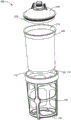
FIG. 4C is an exploded isometric view of one embodiment of a spray gun cup including a liner (including volumetric markings) according to the present disclosure;
FIG. 4D is an exploded isometric view of an embodiment of a spray gun cup according to the present disclosure;
FIG. 5A is an isometric view of an embodiment of a spray gun cup according to the present disclosure;
FIG. 5B is an isometric view of one embodiment of a spray gun cup including volumetric markings according to the present disclosure;
FIG. 5C is an exploded isometric view of one embodiment of a spray gun cup including a liner (including volumetric markings) according to the present disclosure;
FIG. 5D is an exploded isometric view of an embodiment of a spray gun cup according to the present disclosure;
Detailed Description
It should be noted that in the drawings, some elements may exist in the same or equivalent multiples; in this case, one or more representative elements may be designated by reference numerals only, but it should be understood that such reference numerals apply to all such identical elements.
Fig. 1A and 1B illustrate an exemplary embodiment of a spray gun cup receiver 100 according to the present disclosure. The spray gun cup receiver 100 includes an open end 110 that provides access to an internal cavity 120. Opposite the open end 110 is a base end 130. As shown, the base end 130 includes a substantially flat configuration with optional feet 132, allowing the base to be stably seated directly on a flat work surface W (not shown in fig. 1A). The number, shape and arrangement of the legs 132 may be varied as desired. In some embodiments, the base end itself is not flat, but may be held stationary on a work surface as described above with the aid of additional structure (i.e., a retainer, etc.).
Whether or not the base end is flat, a base end plane 134 can be drawn parallel to the work surface W through the base end (when at rest and upright as noted above), as shown in fig. 1B.
In this embodiment, sidewall 140 surrounds cavity 120 and connects open end 110 to base end 130. The side wall 140 includes a series of openings 150 (at least two, but in this particular embodiment eight) through the side wall 140 to allow the contents of the cavity 120 to be viewed through the openings. There is no requirement as to how much material is required to form the sidewalls 140; it should be understood that sidewall 140 is present as long as open end 110 and base end 130 are connected. As shown, the opening 150 is separated by a support member 160 and a bearing member 166. Generally, the support member 166 provides support in an axial direction (along the central axis 101 and orthogonal to the base end plane 134), while the support member 160 provides, inter alia, hoop strength to the spray gun cup receiver 100 at an intermediate location between the open end 110 and the base end 130. In the embodiment shown, there are four vertical support members 166. However, it is envisioned that there may be a different number of support members (e.g., one, two, three, five, six, or seven or more), and that the support members may be non-vertical or only substantially vertical. "substantially vertical" means that an imaginary straight line drawn to represent the average of the trajectory of the support member from the base end to the open end is within +/-five degrees of a vertical plane. It should be understood that the term "vertical" as used herein refers to an orientation that assumes a geometry of a spray gun cup receiver resting on a horizontal plane (a flat work surface) with a flat base end positioned.
In some embodiments, the sidewall 140 of the spray gun cup receiver 100 may be highly open such that relatively minimal support structure (e.g., support members and/or bearing members) is provided. In such a case, it may be advantageous to construct the spray gun cup receiver (and particularly the sidewall 140) from a relatively strong material, such as filled polyamide.
As can further be seen in the embodiment of fig. 1A and 1B, the spray gun cup receptacle includes a receptacle connection structure 170 proximate the open end thereof. The receiver attachment structure 170 allows a separate cover member 300 (not shown in fig. 1A-1D) to be secured to the spray gun cup receiver. As shown, the receiver attachment structure 170 includes threads. However, other connection structures may be employed to provide different connection mechanisms (e.g., a screw wedge connection, a snap-fit connection, a push-fit connection, a twist-lock connection, a clip connection, a latch connection, a hinged connection, or combinations thereof).
Turning now to FIG. 1C, a spray gun cup receiver 100 similar to those shown in FIGS. 1A and 1B is also provided with a volumetric marking "V". The volumetric marker provides a way for the painter to determine the volume and/or ratio of the liquid components in the cavity. The volumetric marking may be provided as a separate liner (see, e.g., fig. 4C and 5C), embossed or otherwise provided on the liner, or otherwise positioned between the spray gun cup receptacle and the cavity that may contain the liquid.
As can be seen in fig. 1B and 1C, the support members are disposed at a suitable support member angle a that allows viewing of volumetric markings at any height within the cavity. For example, while the "10 oz" indicia is hidden behind the support member as shown in fig. 1C, simply rotating the volumetric indicia will allow it to be seen (e.g., by rotating the volumetric indicia so that the "12 oz" will appear in the lower right opening). Alternatively or in addition, the volumetric marking may be repeated such that the same volumetric marking appears in more than one position, wherein at least one of the positions is not visually occluded by the support member. In this way, the provision of the support member may allow the volume of the contents at any level to be accurately determined.
In the exemplary embodiment of fig. 1A and 1B, the support member angle a has a magnitude of about 7.5 degrees, based on the base end plane 134. In the embodiment of fig. 1C, the support member angle a has a magnitude of about 25 degrees, relative to the base end plane 134 (for the trajectory "T" described below to be more visually apparent). However, the support member angle α (or "angles" in the case of more complex shapes) may be selected to be any angle greater than 0 degrees and less than 90 degrees (i.e., the support member is neither parallel nor orthogonal to the base end plane), which both facilitates the structural requirements of the spray gun cup receiver and provides visibility at all levels of the cavity as described herein through the at least one opening. The support member 160 should divide at least two openings such that the openings are positioned vertically at least partially one above the other, and therefore a support member angle a much less than 90 degrees (e.g., 30 degrees or less) is desirable for maximum lance cup receiver size and geometry. As can be seen in the embodiment of the figures, the openings are divided by support members arranged at a support member angle α such that the upper opening is positioned higher than the lower opening, allowing visibility at all liquid levels.
In some embodiments, there are different corresponding angles α1、α2、α3Etc. a plurality of support members 160 may be formed into more complex shapes (see, e.g., fig. 2 and 3). In some embodiments, the support member angle α is at least about 2 degrees with respect to the base end plane 134. In some embodiments, the support member angle α is less than or equal to about 30 degrees with respect to the base end plane 134. In some embodiments, the support member angle a is in a range of about 2 degrees to about 30 degrees, including but not limited to 4 degrees, 7 degrees, 11.5 degrees, 16 degrees, and 25 degrees, including any angle therein, with respect to the base end plane 134.
As shown in the embodiment of FIG. 1D, the trajectory "T" followed by the support member 160 when it circumscribes the cavity 120 can be described as a non-circular ellipse. As used herein, "non-circular ellipse" refers to an ellipse whose eccentricity is not zero. In embodiments where the sidewall of the spray gun cup receptacle is generally cylindrical, the eccentricity may be calculated as the sine of the support member angle α in degrees (i.e., the eccentricity SIN (α)). Generally, for such embodiments, the eccentricity will increase with increasing support member angle α, and vice versa. In some embodiments, the eccentricity of trajectory "T" is at least 0.03. In some embodiments, the eccentricity of trajectory "T" is less than or equal to 0.5. In some embodiments, the eccentricity of trajectory "T" is in the range of about 0.03 to about 0.5.
It should be understood that the trajectory "T" need not be strictly elliptical to fall within the scope of this disclosure. For example, the spray gun cup receiver may be formed to be generally cylindrical, but with a slight draft angle (e.g., about 3 degrees), such that its profile increases from the base end to the open end, resulting in a trajectory "T" along the support member angle α that is generally elliptical, but in fact slightly "egg-shaped".
In other embodiments, the support member may follow a different trajectory or trajectories. For example, fig. 2 and 3 illustrate an alternative embodiment of a spray gun cup receiver that includes more than one support member arranged in a different manner than the embodiment of fig. 1A-1D. Alternatively or in combination, the support members may be arranged to follow a trajectory whose support member angle α varies as its position around the side wall varies-for example, a sine wave, square wave or a sawtooth pattern. Such waves or patterns may be repetitive or irregular. Further, while the embodiments of the lance cup receivers shown herein all show a generally circular cross-section, this need not be the case. For example, the cross-sectional shape of the spray gun cup receiver at any given height may comprise a polygon, such as a hexagon or octagon, or any other shape that allows for the functional purposes set forth herein. For example, in all cases, the support member will be shaped and arranged to allow visibility of the cavity as described elsewhere herein.
Fig. 4A illustrates a spray gun cup 500 including the spray gun cup receiver 100 as shown (e.g., in fig. 1A). This embodiment includes a gasket 200 located in the cavity of the spray gun cup receiver. The liner 200 has an open end 210 (see fig. 4C-4D) corresponding to the open end of the spray gun cup receiver. The cover member 300 is secured to the spray gun cup receiver, the liner, or both. The cover member 300 can be fixed in various ways. As shown in fig. 4A-4D, an optional collar 400 (compare fig. 5A-5D) traps the cap member and liner between the collar and the spray gun cup receptacle via collar connection structure 470 (in this case threads). Any of the receiver connection structures 170 described earlier may be used in a similar manner to allow the optional collar 400 to be attached to the rest of the spray gun cup. Additionally or alternatively, the cap member 300 itself may be provided with the cap connection structure 370 to complement the collar connection structure 470. In such embodiments, for example, the collar 400 may be configured to attach from below the cap member 300 to trap the liner 200 between the cap member 300 and the collar 400. In such embodiments (and in other embodiments described herein), the spray gun cup receiver may remain with the spray gun cup during spraying, or the cap, liner, and collar may be detached or removed as a unit from the spray gun cup receiver 100 during spraying (in which case the spray gun cup receiver 100 may function primarily only as a mixing container).
As shown, the cap member 300 includes a liquid outlet 310 and one or more outlet connection members 320 to allow the cap 300 to be connected to a liquid inlet of a spray gun. The outlet connection member 320 may be disposed on, near, adjacent to, or remote from the liquid outlet 310 so long as it facilitates a secure and fluid-tight connection with the spray gun. Optionally, the lid includes a filter (not shown) to allow the liquid in the spray gun cup to be filtered prior to spraying.
Fig. 4B shows an embodiment as in fig. 4A further comprising volumetric markings V as described elsewhere herein.
FIG. 4C shows an exploded view of the spray gun cup 500 including volumetric markings disposed on the liner 600. As shown, it can be seen that the bushing 600 may comprise a sheet of material that is capable of deforming into the cavity of the spray gun cup receiver upon insertion. Alternatively, the liner 600 may be provided as a pre-molded unit that may be dropped into the spray gun cup receiver 100 without deforming.
The corresponding receiving geometry of the bushing 600 or the spray gun cup receiver 100 may be configured such that the bushing 600 is aligned in the cavity and relative to the opening, and thus is substantially fixed against rotation. In such embodiments, the liner 600 may be provided with repeating volumetric markings "V" as described above such that each liquid level is visible from at least one location around the spray gun cup receptacle. In some embodiments, the bushing 600 may be capable of being aligned in more than one position such that the bushing may be inserted and secured in more than one position.
Fig. 4D shows an exploded view of the spray gun cup 500 without the volumetric markings V included, but nonetheless with the contents of the cavity visible at all fluid levels through at least one opening as described elsewhere herein. The liner 200, if provided, is typically constructed of a transparent or translucent material in order to make the contents of the liner visible.
Fig. 5A shows a spray gun cup 500 that differs from the spray gun cup shown in fig. 4A in that the collar 400 is not used. Rather, the cover member 300 is adapted to be secured without the need for a collar. While originally configured as described above, the cap member 300 may be provided with a cap connection structure 370, which may alternatively be provided on the collar 400. For example, the cover member 300 itself may be threaded directly into the spray gun cup receiver 100 (via the cover connection structure 370), or onto or simultaneously therein. Alternatively (or in combination), the cover member 300 can include a cover connection structure 370 to complement the receiver connection structure 170 previously discussed with respect to fig. 1A (e.g., a snap-fit connection, a push-fit connection, a twist-lock connection, a clip connection, a latch connection, a hinged connection, or a combination thereof).
Fig. 5B shows an embodiment as in fig. 5A further comprising volumetric markings V as described elsewhere herein.
FIG. 5C shows an exploded view of the spray gun cup 500 including volumetric markings disposed on the liner 600. As shown, it can be seen that the sleeve 600 may comprise a sheet of material that is capable of deforming into the cavity of the spray gun cup receiver 100 upon insertion. Alternatively, the liner 600 may be provided as a pre-molded unit that may be dropped into the spray gun cup receiver 100 without deforming.
Fig. 5D shows an exploded view of the spray gun cup 500 without the volumetric markings, but nonetheless with the contents of the cavity visible at all fluid levels through at least one opening as described elsewhere herein. As shown in both fig. 5C and 5D, the cover connection structure 370 includes a snap-fit connection with the complementary receiver connection structure 170. The liner 200, if provided, is typically constructed of a transparent or translucent material in order to make the contents of the liner visible.
It should be further appreciated that while various aspects and embodiments have been disclosed herein, other aspects and embodiments will be apparent to those skilled in the art. The various aspects and embodiments disclosed herein are for purposes of illustration and are not intended to be limiting, with the true scope and spirit being indicated by the following claims. Other embodiments may be utilized, and other changes may be made, without departing from the spirit or scope of the subject matter described herein. It will be readily understood that the aspects of the present disclosure, as generally described herein, and illustrated in the figures, can be arranged, substituted, combined, separated, and designed in a wide variety of different combinations, all of which are contemplated herein.
Claims (20)
1. A spray gun cup receiver comprising
An open end for receiving a liner within the cavity;
a base end opposite the open end, the base end positionable relative to a work surface with the open end facing upward such that a datum plane through the base end is parallel to the work surface;
a sidewall surrounding the cavity and connecting the open end to the base end, the sidewall comprising two openings through which the cavity is visible from outside the spray gun cup receiver, the two openings being separated one above the other by a support member, at least a portion of the support member being disposed at a support member angle a relative to the reference plane, the support member angle a being greater than 0 degrees and less than 90 degrees such that visibility at all liquid levels of the cavity is provided through at least one opening.
2. The spray gun cup receiver of claim 1 wherein the support member angle a is sufficient such that the cavity is visible through at least one of the two openings at any vertical position within the cavity.
3. The spray gun cup receiver of any one of claims 1 or 2 wherein the support member defines a support member trajectory T around the cavity, the support member trajectory comprising an ellipse.
4. The spray gun cup receiver of any one of claims 1 or 2 wherein the support member angle a is at least 2 degrees.
5. The spray gun cup receiver of any of claims 1 or 2 wherein the support member angle a is less than or equal to 30 degrees.
6. The spray gun cup receiver of any one of claims 1 or 2 wherein the open end includes receiver attachment structure to allow a cover member to be secured to the open end.
7. The spray gun cup receiver of claim 6 wherein the receiver connection structure allows for securing the cover member by one of the following connections: threaded connection, spiral wedge connection, push-fit connection, twist-lock connection, clip connection, and strap connection.
8. The spray gun cup receiver of any one of claims 1 or 2 wherein the sidewall includes one or more substantially vertical support members intersecting the support member.
9. A spray gun cup comprises
The spray gun cup receiver of any one of claims 1 or 2; and
a liner located in the cavity, the liner including an open end corresponding to the open end of the spray gun cup receiver.
10. The spray gun cup of claim 9 including a volumetric marking location visible through the opening and indicative of a volume of contents of the liner.
11. The spray gun cup of claim 10 wherein the volumetric markings are on the liner.
12. The spray gun cup of claim 10 wherein the volumetric markings are provided on a bushing positioned between the spray gun cup receiver and the liner.
13. The spray gun cup of claim 9 comprising a cover member secured to the open end of the spray gun cup receiver.
14. The spray gun cup of claim 13 wherein the open end of the liner is secured by interaction of the cover member with the open end of the spray gun cup receiver.
15. A method of using a spray gun cup comprising
Positioning a spray gun cup receiver according to any one of claims 1 or 2 on a work surface;
inserting a liner into the open end of the spray gun cup receiver;
adding a liquid to the pad; and
viewing a level of the liquid through an opening in the sidewall of the spray gun cup receptacle.
16. The method of claim 15, comprising inserting a liner including volumetric markings into the open end of the spray gun cup receiver prior to inserting the liner into the open end of the spray gun cup receiver.
17. The method of claim 16, comprising determining the volume of the liquid by viewing the volumetric marking through the opening.
18. The method of claim 15, comprising adding additional liquid to the liner and viewing a level of the combined liquid through an opening in the sidewall of the spray gun cup receiver.
19. The method of claim 15, comprising securing a cover to the open end of the spray gun cup receiver, the cover including a liquid outlet.
20. The method of claim 19, comprising attaching the liquid outlet to a spray gun.
Applications Claiming Priority (3)
| Application Number | Priority Date | Filing Date | Title |
|---|---|---|---|
| US201562189954P | 2015-07-08 | 2015-07-08 | |
| US62/189,954 | 2015-07-08 | ||
| PCT/US2016/041297 WO2017007911A1 (en) | 2015-07-08 | 2016-07-07 | Spray gun cups, receptacles, and methods of use |
Publications (2)
| Publication Number | Publication Date |
|---|---|
| CN107847956A CN107847956A (en) | 2018-03-27 |
| CN107847956B true CN107847956B (en) | 2021-08-10 |
Family
ID=56411965
Family Applications (1)
| Application Number | Title | Priority Date | Filing Date |
|---|---|---|---|
| CN201680040360.1A Active CN107847956B (en) | 2015-07-08 | 2016-07-07 | Spray gun cup, receiver and method of use |
Country Status (7)
| Country | Link |
|---|---|
| US (1) | US10576490B2 (en) |
| EP (1) | EP3319733B1 (en) |
| JP (1) | JP6807915B2 (en) |
| CN (1) | CN107847956B (en) |
| AU (1) | AU2016290087B2 (en) |
| CA (1) | CA2991762A1 (en) |
| WO (1) | WO2017007911A1 (en) |
Families Citing this family (8)
| Publication number | Priority date | Publication date | Assignee | Title |
|---|---|---|---|---|
| US10857553B2 (en) | 2013-12-05 | 2020-12-08 | 3M Innovative Properties Company | Container for a spraying device |
| USD792556S1 (en) | 2015-07-08 | 2017-07-18 | 3M Innovative Properties Company | Spray gun cup receptacle |
| CA2991762A1 (en) | 2015-07-08 | 2017-01-12 | 3M Innovative Properties Company | Spray gun cups, receptacles, and methods of use |
| CA3011435A1 (en) | 2016-01-15 | 2017-07-20 | 3M Innovative Properties Company | Spray gun cups, receptacles, and methods of use |
| CA3011437C (en) | 2016-01-15 | 2024-02-13 | 3M Innovative Properties Company | Spray gun cups, receptacles, lids, and methods of use |
| CA3011425A1 (en) | 2016-01-15 | 2017-07-20 | 3M Innovative Properties Company | Modular spray gun lid assemblies and methods of design and use |
| JP2020528851A (en) * | 2017-07-14 | 2020-10-01 | スリーエム イノベイティブ プロパティズ カンパニー | Fluid delivery assembly for spray guns |
| EP4082671A1 (en) * | 2021-04-30 | 2022-11-02 | Tai Zhou Luxi Tools Co., Ltd. | Foldable cup and spray cup |
Family Cites Families (54)
| Publication number | Priority date | Publication date | Assignee | Title |
|---|---|---|---|---|
| US3157360A (en) * | 1963-02-25 | 1964-11-17 | William L Heard | Spray gun having valved flexible liner |
| US4174071A (en) * | 1976-11-08 | 1979-11-13 | Binks Manufacturing Company | Spray gun assembly |
| FR2620424B1 (en) | 1987-09-15 | 1989-12-15 | Morel Simone | REMOVABLE HOOD CONTAINER WITH ALIGNED SIDE GENERATORS |
| GB2298194A (en) | 1995-02-24 | 1996-08-28 | Beeson & Sons Ltd | Child resistant closures for containers |
| EP1961488B2 (en) | 1997-01-24 | 2021-02-24 | 3M Company | Apparatus for spraying liquids, and disposable containers and liners suitable for use therewith |
| US6820824B1 (en) * | 1998-01-14 | 2004-11-23 | 3M Innovative Properties Company | Apparatus for spraying liquids, disposable containers and liners suitable for use therewith |
| JP3052058U (en) * | 1998-03-06 | 1998-09-11 | 株式会社ヨトリヤマ | Paint container of paint suction type spray coating machine |
| US6375031B1 (en) | 1999-07-26 | 2002-04-23 | Merry Chance Industries, Ltd. | Container for liquids having viewing window |
| US6536687B1 (en) | 1999-08-16 | 2003-03-25 | 3M Innovative Properties Company | Mixing cup adapting assembly |
| GB0110025D0 (en) | 2001-04-24 | 2001-06-13 | 3M Innovative Properties Co | Improvements in or relating to liquid spraying apparatus |
| US7188785B2 (en) * | 2001-04-24 | 2007-03-13 | 3M Innovative Properties Company | Reservoir with refill inlet for hand-held spray guns |
| US6588681B2 (en) * | 2001-07-09 | 2003-07-08 | 3M Innovative Properties Company | Liquid supply assembly |
| AUPR991202A0 (en) | 2002-01-10 | 2002-01-31 | Owens-Illinois Closure Inc. | A self-venting sports type closure |
| DE20202123U1 (en) | 2002-02-13 | 2003-02-06 | Sata Farbspritztechnik | Paint spray gun comprises body and paint reservoir interconnected by helical wedge connection with helical wedge element which by cut-out extends over more than half circumference of connecting piece |
| US6739781B2 (en) | 2002-04-22 | 2004-05-25 | Seaquist Closures Foreign, Inc. | Scrubbing structure |
| GB0224698D0 (en) | 2002-10-24 | 2002-12-04 | 3M Innovative Properties Co | Easy clean spray gun |
| US7845582B2 (en) * | 2002-12-18 | 2010-12-07 | 3M Innovative Properties Company | Spray gun reservoir with oversize, fast-fill opening |
| US6796514B1 (en) * | 2003-05-02 | 2004-09-28 | 3M Innovative Properties Company | Pre-packaged material supply assembly |
| US6945429B2 (en) | 2003-06-10 | 2005-09-20 | Illinois Tool Works Inc. | Disposable paint cup attachment system for gravity-feed paint sprayer |
| FR2859118B1 (en) | 2003-08-26 | 2007-03-09 | Michel Camilleri | DISPOSABLE BUCKET TO BE MOUNTED ON A GUN FOR THE PREPARATION, APPLICATION AND PRESERVATION OF A PAINT |
| CA2448110A1 (en) | 2003-11-05 | 2005-05-05 | Simon Yechouron | Paint gun accessory |
| US7086549B2 (en) * | 2004-01-16 | 2006-08-08 | Illinois Tool Works Inc. | Fluid supply assembly |
| DE102004003438A1 (en) | 2004-01-22 | 2005-08-18 | Sata Farbspritztechnik Gmbh & Co.Kg | Gravity cup for a paint spray gun |
| DE202004003116U1 (en) | 2004-02-28 | 2005-07-14 | Sata Farbspritztechnik Gmbh & Co.Kg | Flow cup for paint spray gun, has connector directly formed over cap that is attachable on cup-form container, and including connecting piece and helical spline unit for direct attachment of cup to gun |
| CA2595507C (en) * | 2004-12-16 | 2014-08-12 | Louis M. Gerson Co., Inc. | Liquid supply cup and liner assembly for spray guns |
| CN2873651Y (en) * | 2005-08-18 | 2007-02-28 | 苏东华 | Improvement for cup utensil container display window and pattern structure |
| EP1818106A1 (en) * | 2006-02-11 | 2007-08-15 | J. Wagner GmbH | Spray gun |
| PL2029285T3 (en) * | 2006-06-20 | 2013-04-30 | Saint Gobain Abrasives Inc | Liquid supply assembly |
| GB2449891B (en) * | 2007-06-06 | 2012-04-04 | Mark Moran | Drinking device and method of drinking |
| EP2000218A1 (en) * | 2007-06-07 | 2008-12-10 | S.A. Omniform | Self regulating vent for a paint supply vessel. |
| NL1033999C2 (en) | 2007-06-18 | 2008-12-22 | Emm Productions B V | A spray cup lid, method for releasing a bellows in a spray cup and a flange for placement between a spray cup and a lid. |
| MX2010000479A (en) | 2007-07-13 | 2010-06-23 | Seaquist Closures Loeffler Gmbh | Detachable rebounding closure system for a receptacle. |
| DE102007048440B3 (en) | 2007-10-02 | 2009-04-16 | G-Mate Ag | Lid for mixing cups of paint spray guns |
| CN101909756B (en) * | 2007-11-20 | 2013-10-16 | 3M创新有限公司 | Sample preparation and collection system and method |
| CN101856639A (en) * | 2010-06-22 | 2010-10-13 | 上海法固电子科技有限公司 | Paint kettle for paint spray gun |
| DE202011100181U1 (en) | 2011-05-03 | 2012-08-06 | Geka Gmbh | Applikatorschnellverschluss |
| EP2704848B1 (en) * | 2011-05-06 | 2019-07-03 | Saint-gobain Abrasives, Inc | Paint cup assembly with an extended ring |
| IN2014CN02786A (en) * | 2011-10-12 | 2015-07-03 | 3M Innovative Properties Co | |
| IN2014DN03195A (en) | 2011-10-27 | 2015-05-22 | Graco Minnesota Inc | |
| JP6185940B2 (en) * | 2012-03-06 | 2017-08-23 | スリーエム イノベイティブ プロパティズ カンパニー | Spray gun with internal boost passage |
| CN202941842U (en) * | 2012-12-07 | 2013-05-22 | 福建茶花家居塑料用品有限公司 | Portable plastic glass cup |
| CN202941843U (en) * | 2012-12-07 | 2013-05-22 | 福建茶花家居塑料用品有限公司 | Plastic glass cup |
| US9352343B2 (en) * | 2013-01-22 | 2016-05-31 | Carlisle Fluid Technologies, Inc. | Liquid supply system for a gravity feed spray device |
| AU2014262656B2 (en) | 2013-05-08 | 2018-08-09 | Graco Minnesota Inc. | Paint can adapter for handheld spray device |
| US20150108135A1 (en) | 2013-10-17 | 2015-04-23 | Fadi Hanna | Disposable components for a spray gun |
| US10857553B2 (en) * | 2013-12-05 | 2020-12-08 | 3M Innovative Properties Company | Container for a spraying device |
| US9796492B2 (en) * | 2015-03-12 | 2017-10-24 | Graco Minnesota Inc. | Manual check valve for priming a collapsible fluid liner for a sprayer |
| CA2991762A1 (en) | 2015-07-08 | 2017-01-12 | 3M Innovative Properties Company | Spray gun cups, receptacles, and methods of use |
| CA3011425A1 (en) * | 2016-01-15 | 2017-07-20 | 3M Innovative Properties Company | Modular spray gun lid assemblies and methods of design and use |
| PL3402604T3 (en) | 2016-01-15 | 2021-07-19 | 3M Innovative Properties Company | Wide-mouthed fluid connector for hand-held spray guns |
| US10689165B2 (en) | 2016-01-15 | 2020-06-23 | 3M Innovative Properties Company | Reservoir systems for hand-held spray guns and methods of use |
| JP2019504753A (en) | 2016-01-15 | 2019-02-21 | スリーエム イノベイティブ プロパティズ カンパニー | Button lock fluid connector for handheld spray gun |
| CN108472669B (en) | 2016-01-15 | 2021-10-01 | 3M创新有限公司 | Connector system for a hand-held spray gun |
| CA3011435A1 (en) * | 2016-01-15 | 2017-07-20 | 3M Innovative Properties Company | Spray gun cups, receptacles, and methods of use |
-
2016
- 2016-07-07 CA CA2991762A patent/CA2991762A1/en not_active Abandoned
- 2016-07-07 CN CN201680040360.1A patent/CN107847956B/en active Active
- 2016-07-07 JP JP2018500460A patent/JP6807915B2/en active Active
- 2016-07-07 EP EP16738999.8A patent/EP3319733B1/en active Active
- 2016-07-07 AU AU2016290087A patent/AU2016290087B2/en not_active Ceased
- 2016-07-07 WO PCT/US2016/041297 patent/WO2017007911A1/en active Application Filing
- 2016-07-07 US US15/736,469 patent/US10576490B2/en active Active
Also Published As
| Publication number | Publication date |
|---|---|
| WO2017007911A1 (en) | 2017-01-12 |
| US10576490B2 (en) | 2020-03-03 |
| EP3319733B1 (en) | 2020-11-11 |
| CA2991762A1 (en) | 2017-01-12 |
| AU2016290087A1 (en) | 2018-02-01 |
| JP6807915B2 (en) | 2021-01-06 |
| AU2016290087B2 (en) | 2019-04-04 |
| JP2018520867A (en) | 2018-08-02 |
| CN107847956A (en) | 2018-03-27 |
| US20180185869A1 (en) | 2018-07-05 |
| EP3319733A1 (en) | 2018-05-16 |
Similar Documents
| Publication | Publication Date | Title |
|---|---|---|
| CN107847956B (en) | Spray gun cup, receiver and method of use | |
| US11919027B2 (en) | Modular spray gun lid assemblies and methods of design and use | |
| EP3402603B1 (en) | Spray gun cups, receptacles, and methods of use | |
| US7165732B2 (en) | Adapter assembly for a fluid supply assembly | |
| US4273272A (en) | Liquid dispenser | |
| EP3402602B1 (en) | Spray gun cups, receptacles, lids, and methods of use | |
| CA2549738A1 (en) | Asymmetrical spray nozzle with alignment notch | |
| US20230219106A1 (en) | Spray gun cups, receptacles, lids, and methods of use | |
| US10434527B1 (en) | Fluid dispensing system |
Legal Events
| Date | Code | Title | Description |
|---|---|---|---|
| PB01 | Publication | ||
| PB01 | Publication | ||
| SE01 | Entry into force of request for substantive examination | ||
| SE01 | Entry into force of request for substantive examination | ||
| GR01 | Patent grant | ||
| GR01 | Patent grant |