EP1209828A2 - Optisches Übertragungssystem und optisches Übertragungsverfahren - Google Patents
Optisches Übertragungssystem und optisches Übertragungsverfahren Download PDFInfo
- Publication number
- EP1209828A2 EP1209828A2 EP01309967A EP01309967A EP1209828A2 EP 1209828 A2 EP1209828 A2 EP 1209828A2 EP 01309967 A EP01309967 A EP 01309967A EP 01309967 A EP01309967 A EP 01309967A EP 1209828 A2 EP1209828 A2 EP 1209828A2
- Authority
- EP
- European Patent Office
- Prior art keywords
- optical
- error rate
- rate information
- signal
- transmission line
- Prior art date
- Legal status (The legal status is an assumption and is not a legal conclusion. Google has not performed a legal analysis and makes no representation as to the accuracy of the status listed.)
- Withdrawn
Links
Images


Classifications
-
- H—ELECTRICITY
- H04—ELECTRIC COMMUNICATION TECHNIQUE
- H04B—TRANSMISSION
- H04B10/00—Transmission systems employing electromagnetic waves other than radio-waves, e.g. infrared, visible or ultraviolet light, or employing corpuscular radiation, e.g. quantum communication
- H04B10/25—Arrangements specific to fibre transmission
- H04B10/2507—Arrangements specific to fibre transmission for the reduction or elimination of distortion or dispersion
- H04B10/2513—Arrangements specific to fibre transmission for the reduction or elimination of distortion or dispersion due to chromatic dispersion
Definitions
- the present invention relates to an optical transmission system and an optical transmission method and more particularly, to an optical transmission system and an optical transmission for compensating for any wavelength deterioration of a light signal based on a wavelength dispersion of an optical fiber transmission line.
- a light signal for example, a light signal modulated with a non-return-to-zero (NRZ) signal of 10 Gb/s
- the light signal's pulse waveform is deteriorated due to the wavelength dispersion characteristics of the optical fiber, thus degrading the receiving sensitivity.
- an erbium doped fiber amplifier Since in recent years, an erbium doped fiber amplifier has been developed for practical use, the distance between optical repeaters is increased. Thus, wavelength dispersion of an optical fiber transmission line has become a main cause for deterioration in transmission characteristics of a light signal.
- the bit rate of a light signal is increased with a narrowed spectral bandwidth, the light signal will be greatly affected by wavelength dispersion.
- FIGS. 1A and 1B show an example of wavelength dispersion characteristics of an optical fiber.
- FIG. 1A shows the relationship between light wavelength ⁇ and propagation delay time ⁇ g and
- FIG. 1B shows the relationship between light wavelength ⁇ and wavelength dispersion D.
- FIGS. 2A to 2C show that the optical frequency varies at the leading and trailing edges of a generated optical pulse when a laser beam is intensity-modulated through electroabsorption optical modulation (hereinafter called EA optical modulation) .
- a letter ⁇ in FIGS. 2B and 2C denotes a chirp coefficient, which is a parameter for showing a frequency variation.
- FIG. 2B shows that for ⁇ > 0, the optical frequency increases at the leading edge of the optical pulse and the optical frequency decreases at the trailing edge of the optical pulse.
- FIG. 2C shows that for ⁇ ⁇ 0, the optical frequency decreases at the leading edge of the optical pulse and the optical frequency increases at the trailing edge of the optical pulse.
- a modulated optical pulse with a chirp coefficient ⁇ more than zero has a short-wavelength component at the leading edge and a long-wavelength component at the trailing edge.
- this optical pulse propagates through a region with a wavelength dispersion D more than zero (D > 0)
- the pulse width is increased with a deteriorated pulse waveform because the short-wavelength component propagates there at a higher speed than that of the long-wavelength component.
- this optical pulse propagates through another region with a wavelength dispersion D less than zero (D ⁇ 0)
- the pulse width is decreased with a deteriorated pulse waveform because the short-wavelength component propagates there at a lower speed than that of the long-wave component.
- Another modulated optical pulse with a chirp coefficient ⁇ less than zero also has a deteriorated waveform.
- SPM self-phase modulation
- VTD group velocity dispersion
- Wavelength dispersion and SPM are usually affected by each other. As a result, the waveform of the optical pulse is deteriorated with a degraded receiving sensitivity, and thus, it will be difficult to provide dispersion compensation as designed.
- a dispersion compensator such as a dispersion compensation fiber (DCF) or a chirped fiber grating (CFG) is used.
- DCF dispersion compensation fiber
- CFG chirped fiber grating
- a DCF is an optical fiber which has the capability of canceling wavelength dispersion produced on an optical fiber transmission line.
- the DCF has a small mode field diameter (MFD), which is approximately 4 to 5 ⁇ m. Therefore, in the DCF, its transmission performance is prone to deterioration due to some nonlinear optical effect.
- MFD mode field diameter
- the DCF cannot be bent finely and it is difficult to downsize the dispersion compensator.
- a CFG is a dispersion compensator with a grating formed on the side of an optical fiber in the longitudinal direction.
- the CFG is largely dependent on temperature and thus, it requires a temperature regulation feature.
- a ripple may occur in the CFG as one of the group delay characteristics.
- DCF and CFG are optical passive components, they will necessarily cause an excessive loss of light signal and deteriorate its transmission performance. Both components have a fixed amount of dispersion compensation and thus, a deviation in residual dispersion may occur between channels.
- EA modulator electroabsorption optical modulator which absorbs input light according to an applied voltage
- a variation in a chirp coefficient ⁇ of an EA modulation section may prevent implementation of dispersion compensation as designed.
- an object of at least the preferred embodiment of the present invention to provide an optical transmission system and an optical transmission method which can compensate for wavelength deterioration caused by wavelength dispersion and SPM and improve the receiving sensitivity, without using any dispersion compensator which is an optical passive component.
- a first optical transmission system comprises an optical transmitting device, an optical receiving device, and an optical fiber transmission line placed between these devices.
- the optical transmitting device comprises an encoder for encoding a data signal with an error-correcting code and an optical transmitter for converting the coded data signal into a light signal based on error rate information transmitted by the optical receiving device to provide an output.
- the optical receiving device comprises an optical receiver for converting the received light signal into an electrical signal and a decoder for error-correcting that electrical signal to provide error rate information and a data signal.
- the optical transmission system can comprise a line over which the error rate information is propagated to the optical transmitting device.
- the optical transmitting device further comprises a demodulator for demodulating the error rate information transmitted by the optical receiving device, an optical coupler for branching an error rate information light signal transmitted via the optical fiber transmission line, and an optical receiver for converting the branched light signal into an electrical signal
- the optical receiving device further comprises a modulator for modulating the error rate information provided by the decoder, an optical transmitter for converting the error rate information into a light signal, and an optical coupler for introducing the light signal onto the optical fiber transmission line.
- a third optical transmission system comprises a plurality of optical transmitting devices for transmitting light signals of different wavelengths, a multiplexer for wavelength-multiplexing the plurality of light signals, an optical fiber transmission line over which the wavelength-multiplexed light signal is propagated, a demultiplexer for demultiplexing the wavelength-multiplexed light, and a plurality of optical receiving devices for receiving light signals of the corresponding wavelengths.
- each optical transmitting device comprises an encoder for encoding a data signal with an error-correcting code and an optical transmitter for converting the coded data signal into a light signal based on error rate information transmitted by the corresponding optical receiving device toprovide an output
- each optical receiving device comprises an optical receiver for converting the received light signal into an electrical signal and a decoder for error-correcting that electrical signal to provide error rate information and a data signal.
- the third system further comprises a line over which the above-mentioned error rate information is transmitted to the optical transmitter.
- a fourth optical transmission system is an optical transmission system which comprises two stations, and a down optical fiber transmission line and an up optical fiber transmission line placed between them.
- Each of the above-mentioned stations comprises an optical transmitting section and an optical receiving section.
- the optical transmitting section comprises a plurality of optical transmitting devices for transmitting light signals of different wavelengths and a multiplexer for wavelength-multiplexing the plurality of light signals.
- the optical receiving section comprises a demultiplexer for demultiplexing the wavelength-multiplexed light and a plurality of optical receiving devices for receiving light signals of the corresponding wavelengths.
- the above-mentioned optical transmitting device comprises an encoder for encoding a data signal with an error-correcting code and an optical transmitter for converting the coded data signal into a light signal based on error rate information transmitted by the corresponding optical receiving device to provide an output
- the above-mentioned optical receiving device comprises an optical receiver for converting the received light signal into an electrical signal and a decoder for error-correcting that electrical signal to provide error rate information and a data signal.
- each decoder of the optical receiving section transmits error rate information to the corresponding encoder of the optical transmitting section and that error rate information is transmitted to the second station.
- each decoder of the optical receiving section transmits error rate information to the optical transmitter of the optical transmitting section.
- the optical fiber transmission line can comprise an optical amplifier for amplifying a light signal transmitted by the optical transmitting device, an optical coupler placed at each of the input and output of that optical amplifier, and an optical fiber directly connecting to these optical couplers.
- the optical fiber transmission line may comprise an optical amplifier.
- the optical transmitter in the optical transmitting device can comprise an electroabsorption modulator for modulating a laser beam through electroabsorption optical modulation based on the coded data signal and drive control means for receiving error rate information and supplying that data signal and a DC bias voltage to that electroabsorption modulator.
- An optical transmission method comprises the steps of encoding a data signal with an error-correcting code, converting this signal into a light signal in an optical transmitter with an electroabsorption modulator to provide an output, error-correcting the signal on the receiving side to provide error rate information, and controlling the electroabsorption modulator based on the error rate information to reduce errors on the receiving side.
- At least the preferred embodiment of the present invention can compensate for wavelength deterioration caused by wavelength dispersion of an optical fiber and improve the receiving sensitivity without a dispersion compensator.
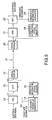
- an optical fiber transmission line 31 is placed between an optical transmitting device and an optical receiving device.
- the optical transmitting device comprises an encoder (ENC) 11 for encoding an electrical data signal with an error-correcting code and an optical transmitter (OTX) 12 for converting the encoded electrical data signal into a light data signal for transmission.
- the optical receiving device comprises an optical receiver (ORX) 21 for receiving the light data signal transmitted by the transmitting device and converting it into an electrical signal and a decoder (DEC) 22 for decoding and error-correcting the electrical signal to provide an electrical data signal and for comparing error rates before and after the error correction process to provide error rate information.
- the decoder (DEC) 22 transmits the error rate information to the optical transmitter (OTX) 12 via a line 36 and the optical transmitter (OTX) 12 controls the light data signal to minimize errors in the decoder 22.
- the line 36 is provided separately from the optical fiber transmission line 31. When a line is provided for communicating management information, this line may be used for transmitting error rate information.
- the above-mentioned encoder (ENC) 11 has the capability of error-correcting and encoding a data signal, for example, through forward error correction (FEC).
- FEC forward error correction
- the encoder 11 redundantly encodes an NRZ electrical data signal of 9.95 Gb/s into a signal of 10.66 Gb/s (S1) to provide an output.
- the optical transmitter 12 intensity-modulates a laser beam of 1.55 ⁇ m in wavelength through EA modulation based on the redundantly-encoded electrical data signal (S1) and the error rate information (S2) to provide a light data signal (S3).
- the optical receiver 21 converts an NRZ light data signal of 10.66 Gb/s into an electrical signal.
- the decoder 22 decodes the FEC redundantly-encoded electrical data signal of 10.66 Gb/s into an NRZ electrical data signal of 9.95 Gb/s to perform an error correction process. In addition, the decoder 22 compares error rates before and after the error correction process to provide the error rate information (S2), that is, the rate of errors which occur on the optical fiber transmission line.
- S2 error rate information
- the optical receiving device further comprises an error rate information modulator 23 for generating an error rate information electrical signal which is AM-modulated with the error rate information and then providing an output.
- the optical transmitting device further comprises an error rate information demodulator 14 for demodulating the error rate information electrical signal transmitted via the line 36 to provide it to the optical transmitter 12.
- the optical receiving device further comprises an error rate information optical transmitter 24 for converting the error rate information into a light signal and an optical coupler 25 for introducing the light signal into the optical fiber transmission line 31.
- a light data signal is transmitted to the optical receiver 21 through the optical fiber transmission line 31 and the optical coupler 25.
- An optical isolator may be placed between the optical coupler 25 and the error rate information optical transmitter 24 as necessary.
- the optical transmitting device further comprises an optical coupler 15 for branching the error rate information light signal transmitted through the optical fiber transmission line 31 and an error rate information optical receiver 13 for converting the light signal into an electrical signal. It is desirable that the wavelength of a light data signal provided by the optical transmitter 12 is different from that of an error rate information light signal provided by the error rate information optical transmitter 24.
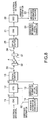
- FIG. 6 shows an example of the optical transmitter (OTX) 12.
- the optical transmitter 12 comprises an EA modulation module 124, and an auto power control (APC) circuit 126 and an auto temperature control (ATC) circuit 127 both for controlling that module.
- the EA modulation module 124 has a structure that an EA modulation section 121, a semiconductor laser 122, and a photodiode 123 are integrated into that module.
- the APC circuit 126 controls so that the semiconductor laser 122 can provide a constant optical output depending on the optical level of the semiconductor laser 122 detected by the photodiode 123.
- the ATC circuit 127 controls the temperature of the semiconductor laser 122 to be able to be kept constant for a stable laser wavelength of the CW laser.
- the optical transmitter 12 further comprises an EA modulation drive amplifier 125 and an EA modulation controller 128.
- the EA modulation drive amplifier 125 supplies the EA modulation section 121 with a coded electrical data signal (S1) superposed with a DC bias voltage.
- the EA modulation controller 128 transmits to the EA modulation drive amplifier 125 a control signal (S4) and a DC bias control signal (S5) for controlling the electrical data signal (S1) and the level of the DC bias voltage, respectively.
- the EA modulation section 121 receives a CW laser beam provided by the semiconductor laser 122 and then intensify-modulates it according to the NRZ data signal of 10.66Gb/s (S1) supplied by the EA modulation drive amplifier 125.
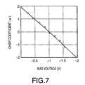
- the chirp coefficient ⁇ of the EA modulation section 121 varies according to the bias voltage as shown in FIG. 7.
- FIG. 7 shows the characteristics that the chirp coefficient ⁇ varies from a positive value to a negative value when the bias voltage drops from 0 V.
- the EA modulation controller 128 generates a level control signal (S4) and a DC bias control signal (S5) for providing an optimum chirp coefficient ⁇ in order to minimize the error rate of a data signal produced on the optical fiber transmission line 31, based on the error rate information (S2). Since the EA modulation section 121 may be damaged when an applied voltage is more than +0.3 V or less than -4 V, it should be appreciated that the DC bias and drive electrical signals must be controlled within the applied voltage range. In addition, the EA modulation section must be controlled to the extent that the extinction ratio may not be affected by the applied voltage.
- the encoder 11 produces a redundant signal of the NRZ electrical data signal of 9.95 Gb/s through FEC and then provides an NRZ electrical data signal (S1) of 10.66 Gb/s.
- the optical transmitter 12 converts the data signal (S1) into a light data signal (S3) and transmits this light signal to the optical receiving device through the optical coupler 15 and the optical fiber transmission line 31.
- the optical fiber transmission line 31 is made of, for example, a single mode fiber of 80 km long.
- the optical receiver 21 converts the light data signal (S3) into an NRZ electrical data signal of 10.66 Gb/s.
- the decoder 22 decodes and error-corrects this data signal to provide an NRZ electrical data signal of 9.95 Gb/s.
- the decoder 22 compares the code error rates before and after the error correction process to provide error rate information (S2) which indicates the rate of errors occurring on the optical fiber transmission line.
- the error rate information modulator 23 converts the error rate information into an AM modulating signal.
- the error rate information optical transmitter 24 converts this AM modulating signal into a light signal and then transmits it to the optical transmitting device via the optical coupler 25 and the optical fiber transmission line 31. It is desirable that the wavelength of this light signal is different from that of the light data signal (S3).
- the error rate information optical receiver 13 receives an error rate information light signal from the optical coupler 15 and converts it into an electrical signal.
- the error rate information demodulator 14 demodulates this electrical signal and transmits the demodulated signal to the optical transmitter 12 as error rate information S2.
- the EA modulation controller 128 receives the error rate information (S2), controls the DC bias voltage and the data signal supplied to the EA modulation section 121, and controls the chirp coefficient ⁇ of the EA modulation section to minimize errors .
- S2 error rate information
- S2 controls the DC bias voltage and the data signal supplied to the EA modulation section 121
- chirp coefficient ⁇ of the EA modulation section to minimize errors .
- an optical amplifier 4 is placed on the optical fiber transmission line to amplify a light data signal.
- a plurality of optical amplifiers may be placed there.
- Optical couplers 52, 51 are provided at the input and the output of the optical amplifier 4, respectively.
- An error rate information light signal introduced from the optical coupler 25 onto the optical fiber transmission line 34 is branched by the optical coupler 51 and then introduced by the optical coupler 52 onto the optical fiber transmission line 33. Even when such an optical amplifier is provided on the optical fiber transmission line, the error rate information can be transmitted to the optical transmitting device by bypassing the optical amplifier 4. If the error rate information light signal is modulated with a low-frequency signal, the light signal requires no optical amplifier because it can be transmitted over a longer distance than a data signal. However, if necessary, an optical amplifier may be provided for the error rate information light signal.
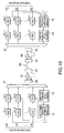
- the third optical transmission system can be applicable to wavelength division multiplexed light.
- the third system has a plurality of optical transmission devices which comprises encoders (ENC) 11-1 to 11-n for encoding data signals on a plurality of channels ch1 to chn, respectively, and has optical transmitters (OTX) 12-1 to 12-n for converting the encoded data signals into light signals, respectively.
- a multiplexer 17 multiplexes the light signals transmitted by these optical transmitters 12-1 to 12-n.
- a multichannel error rate information demodulator 16 demodulates an error rate information electrical signal obtained by multiplexing error rate information for each channel, performs an error correction process as necessary, and then transmits the demodulated signals to the corresponding optical transmitters (OTX) 12-1 to 12-n.
- the optical receiving device comprises a demultiplexer 27 for demultiplexing the multichannel light data signal for each channel, optical receivers (ORX) 21-1 to 21-n for converting a light signal for each channel into an electrical signal, and decoders.
- the decoders (DEC) 22-1 to 22-n decode these electrical signals, respectively, and perform an error correction process on them to provide electrical data signals .
- each decoder compares error rates before and after the error correction process to provide error rate information.
- the multichannel error rate information modulator 26 multiplexes the error rate information, generates an error rate information electrical signal, and then transmits it to the multichannel error rate information demodulator 16 via the line 36.
- the optical fiber transmission line 32 can comprise optical amplifiers 61, 62.
- a multiplexed error rate information is transmitted to the optical transmitting device via the optical fiber transmission line.
- the optical receiving device comprises an error rate information optical transmitter 24 for converting an error rate information electrical signal into a light signal.
- This light signal is introduced onto the optical fiber transmission line 32 through a demultiplexer and transmitted to the optical transmitting device by optical couplers 53, 54, 55, 56 by bypassing optical amplifiers 62, 61.
- the error rate information optical receiver 13 receives error rate information via the multiplexer 17 and then converts it into an electrical signal to transmit the converted signal to the multichannel error rate information demodulator 16.
- FIGS. 9 and 10 the structure of each element and the controlling method are the same as those described above.
- This system can compensate for dispersion without any variation among channels because the chirp coefficient ⁇ of the EA modulation section can be optimally controlled for each channel.
- FIG. 11 shows an example wherein a dispersion compensator 7 is connected to the optical amplifier 62.
- This optical transmission system also can provide dispersion compensation without any variation among channels.
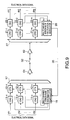
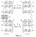
- FIG. 12 shows an example of the fourth optical transmission system wherein each of two optical stations comprises an optical transmitting device and an optical receiving device for servicing wavelength division multiplexing light signals.
- An down optical fiber transmission line 32 is provided between the optical transmitting device in the station A and the optical receiving device in the station B and an up optical fiber transmission line 35 is provided between the optical transmitting device in the station B and the optical receiving device in the station A.
- the optical transmitting device in the station A comprises encoders (ENC) 11-1 to 11-n for encoding electrical data signals on channels ch1 to chn, respectively, and optical transmitters (OTX) 12-1 to 12-n for converting the encoded data signals into light signals, respectively.
- the multiplexer 17 multiplexes the light data signals provided by the optical transmitters (OTX) 12-1 to 12-n to provide an output.
- the optical transmitting device may comprise an optical amplifier 61.
- the optical receiving device in the station B comprises a demultiplexer 27 for demultiplexing a wavelength multiplexed light, optical receivers (ORX) 21-1 to 21-n for receiving light data signals to convert them into electrical signals, and decoders (DEC) 22-1 to 22-n. These decoders decode and error-correct the respective electrical signals to provide a data signal, and in addition, they compare the error rates before and after the error correction process toprovide the respective error rate information.
- the optical transmitting device in the station B may comprise a preliminary optical amplifier 62 for amplifying a multichannel light signal to a predetermined level.
- the optical fiber transmission line can comprise an optical amplifier.
- the optical transmitting device in the station B and the optical receiving device in the station A have the same configuration as those of the optical transmitting device and the optical receiving device in FIG. 9.
- the operation of the fourth optical transmission system will be as described below.
- the encoders (ENC) 81-1 to 81-n of the optical transmitting device receive NRZ electrical data signals of 9.95 Gb/s on the channels ch1 to chn and receive error rate information from the decoders (DEC) 22-1 to 22-n of the optical receiving device.
- Each of the encoders (ENC) 81-1 to 81-n performs an error correction and encoding process through forward error correction (FEC), appends error rate information to the overhead (OH) portion of an FEC frame of a redundant data signal or the OH portion of an SDH/SONET frame, and provides an NRZ electrical data signal of 10.66 Gb/s including the error rate information.
- FEC forward error correction
- the decoders (DEC) 92-1 to 92-n of the optical receiving device receive the electrical data signals including the error rate information from the optical receivers (ORX) 91-1 to 91-n, respectively.
- Each of the decoders (DEC) 92-1 to 92-n extracts the error rate information appended to the OH portion of the FEC frame or the OH portion of the SDH/SONET frame, decodes the redundant electrical data signal for a code error correction process, and then provide an electrical data signal for the corresponding channel ch1 to chn.
- the error rate information is provided to each of the optical transmitters (OTX) 12-1 to 12-n.
- the decoders (DEC) 92-1 to 92-n decode the error rate information.
- the station A comprises a multichannel error rate information demodulator 94.
- This demodulator 94 receives error rate information to perform an error correction process on the error rate information and demodulates the error rate information for each channel to provide it to the optical transmitters (OTX) 12-1 to 12-n, respectively.
- the optical transmitters (OTX) 12-1 to 12-n operate in the same manner as described above.
- the optical fiber transmission line in the fourth optical transmission system requires no optical coupler which would be otherwise provided preceding or following the optical amplifier.
- the systems in shown FIGS. 9 to 12 can comprise a coupler in place of the demultiplexer, if the optical receivers (ORX) have filters.
- the receiving side detects an error rate and sends it back to the transmitting side and the transmitting side in turn controls the chirp coefficient of the EA modulator based on this information to compensate for wavelength deterioration in an optical pulse.
- the present system can reduce wavelength dispersion without dispersion compensator, resulting in an improved receiving sensitivity.
- An optical transmission system includes : an optical transmitting device; and an optical receiving device.
- the optical transmitting device includes : an encoder for encoding a data signal with an error-correcting code; and an optical transmitter, and the optical receiving device includes an optical receiver and a decoder.
- the decoder error-corrects a received signal to provide error rate information.
- the optical transmitter controls a chirp coefficient of an electroabsorption modulator based on the error rate information to minimize errors or error rate.
Landscapes
- Physics & Mathematics (AREA)
- Electromagnetism (AREA)
- Engineering & Computer Science (AREA)
- Computer Networks & Wireless Communication (AREA)
- Signal Processing (AREA)
- Optical Communication System (AREA)
Applications Claiming Priority (2)
| Application Number | Priority Date | Filing Date | Title |
|---|---|---|---|
| JP2000361860 | 2000-11-28 | ||
| JP2000361860A JP2002164846A (ja) | 2000-11-28 | 2000-11-28 | 光伝送システム |
Publications (2)
| Publication Number | Publication Date |
|---|---|
| EP1209828A2 true EP1209828A2 (de) | 2002-05-29 |
| EP1209828A3 EP1209828A3 (de) | 2003-08-20 |
Family
ID=18833233
Family Applications (1)
| Application Number | Title | Priority Date | Filing Date |
|---|---|---|---|
| EP01309967A Withdrawn EP1209828A3 (de) | 2000-11-28 | 2001-11-28 | Optisches Übertragungssystem und optisches Übertragungsverfahren |
Country Status (4)
| Country | Link |
|---|---|
| US (1) | US20020063934A1 (de) |
| EP (1) | EP1209828A3 (de) |
| JP (1) | JP2002164846A (de) |
| CA (1) | CA2363871A1 (de) |
Cited By (1)
| Publication number | Priority date | Publication date | Assignee | Title |
|---|---|---|---|---|
| WO2020178559A1 (en) | 2019-03-06 | 2020-09-10 | Cambridge Enterprise Limited | Optical transmitter |
Families Citing this family (22)
| Publication number | Priority date | Publication date | Assignee | Title |
|---|---|---|---|---|
| JP3522044B2 (ja) * | 1996-04-19 | 2004-04-26 | 富士通株式会社 | 光伝送システム |
| US7734191B1 (en) * | 2002-10-08 | 2010-06-08 | Infinera Corporation | Forward error correction (FEC) enabled photonic integrated circuit (PICs) chips with multiple signal channels |
| JP3910988B2 (ja) | 2002-11-29 | 2007-04-25 | 富士通株式会社 | パケット伝送システム及び端局装置 |
| WO2005013542A1 (ja) | 2003-08-05 | 2005-02-10 | Fujitsu Limited | 再生中継方法及びその装置 |
| US20050047795A1 (en) * | 2003-08-28 | 2005-03-03 | Windover Lisa A. | Optical interconnect system and method of communications over an optical backplane |
| US7542685B2 (en) * | 2004-05-12 | 2009-06-02 | Futurewei Technologies, Inc. | System and method for automatic chromatic dispersion compensation |
| JP5267899B2 (ja) * | 2007-03-28 | 2013-08-21 | 日本電気株式会社 | 波長多重光伝送システム並びに波長多重光伝送方法 |
| WO2009019746A1 (ja) | 2007-08-03 | 2009-02-12 | Fujitsu Limited | 通信装置、通信システム、及び通信方法 |
| JP5870728B2 (ja) | 2012-02-10 | 2016-03-01 | 富士通株式会社 | 光パス確立方法及び光ノード装置 |
| US8983294B2 (en) * | 2012-06-29 | 2015-03-17 | Alcatel Lucent | Forward error correction for an optical transport system |
| WO2015087448A1 (ja) * | 2013-12-13 | 2015-06-18 | 富士通株式会社 | マルチキャリア光伝送システム、マルチキャリア光伝送方法、光送信器、及び、光受信器 |
| US9166628B2 (en) | 2013-12-13 | 2015-10-20 | Alcatel Lucent | Use of parity-check coding for carrier-phase estimation in an optical transport system |
| JP5793218B2 (ja) * | 2014-05-12 | 2015-10-14 | 日本電信電話株式会社 | 光送受信システム |
| JP6661263B2 (ja) * | 2014-09-03 | 2020-03-11 | 富士通株式会社 | 光伝送装置、非線形歪み補償方法及び非線形歪み予等化方法 |
| US9397871B2 (en) * | 2014-09-30 | 2016-07-19 | Infineon Technologies Ag | Communication devices |
| JP2016082402A (ja) * | 2014-10-16 | 2016-05-16 | 富士通株式会社 | ベースバンド処理装置、無線装置、及び無線通信システム |
| JP2016100855A (ja) | 2014-11-26 | 2016-05-30 | 富士通株式会社 | 送信装置、受信装置および通信方法 |
| JP2016208164A (ja) * | 2015-04-20 | 2016-12-08 | ソニー株式会社 | 通信装置、通信システム、および通信方法 |
| CN106572040B (zh) * | 2015-10-12 | 2020-04-21 | 富士通株式会社 | 发射端调制器的偏置漂移估计装置、补偿装置以及接收机 |
| US10187149B2 (en) * | 2017-05-05 | 2019-01-22 | Cisco Technology, Inc. | Downstream node setup |
| CN113325808A (zh) * | 2020-02-28 | 2021-08-31 | 上海诺基亚贝尔股份有限公司 | 控制方法、设备、装置、系统以及计算机可读介质 |
| JP2024058965A (ja) * | 2022-10-17 | 2024-04-30 | 日本電気株式会社 | 光通信システムにおける送信機、ネスト型変調器の制御方法およびプログラム |
Family Cites Families (11)
| Publication number | Priority date | Publication date | Assignee | Title |
|---|---|---|---|---|
| JPS6276331A (ja) * | 1985-09-27 | 1987-04-08 | Nec Corp | 双方向光フアイバ通信方式 |
| FR2694150B1 (fr) * | 1992-07-22 | 1994-08-19 | Cit Alcatel | Système de transmission d'informations numériques, notamment sur une liaison optique. |
| JPH0787021A (ja) * | 1993-09-16 | 1995-03-31 | Fujitsu Ltd | 光ファイバ通信の障害検出方法および装置 |
| JP3017925B2 (ja) * | 1994-04-14 | 2000-03-13 | 株式会社東芝 | 移動通信端末と移動通信方法 |
| JPH07321413A (ja) * | 1994-05-27 | 1995-12-08 | Fuji Xerox Co Ltd | 光中継増幅器 |
| JP3072047B2 (ja) * | 1995-03-22 | 2000-07-31 | 株式会社東芝 | 波長多重光伝送装置および光中継器 |
| JP3132638B2 (ja) * | 1995-08-08 | 2001-02-05 | 日本電気株式会社 | 光波長多重伝送方式 |
| US6171336B1 (en) * | 1996-03-26 | 2001-01-09 | Mark R. Sawusch | Method, implant, and apparatus for refractive keratoplasty |
| JPH10163971A (ja) * | 1996-11-25 | 1998-06-19 | Fujitsu Ltd | 光信号の波長を制御するための方法、装置及びシステム |
| JPH11266200A (ja) * | 1998-03-18 | 1999-09-28 | Fujitsu Ltd | 光ファイバ通信のための方法並びに該方法の実施に使用される装置及びシステム |
| JP2000059308A (ja) * | 1998-08-06 | 2000-02-25 | Mitsubishi Electric Corp | 光伝送システム |
-
2000
- 2000-11-28 JP JP2000361860A patent/JP2002164846A/ja active Pending
-
2001
- 2001-11-27 CA CA002363871A patent/CA2363871A1/en not_active Abandoned
- 2001-11-27 US US09/993,696 patent/US20020063934A1/en not_active Abandoned
- 2001-11-28 EP EP01309967A patent/EP1209828A3/de not_active Withdrawn
Cited By (2)
| Publication number | Priority date | Publication date | Assignee | Title |
|---|---|---|---|---|
| WO2020178559A1 (en) | 2019-03-06 | 2020-09-10 | Cambridge Enterprise Limited | Optical transmitter |
| US12081319B2 (en) | 2019-03-06 | 2024-09-03 | Cambridge Enterprise Limited | Optical transmitter |
Also Published As
| Publication number | Publication date |
|---|---|
| EP1209828A3 (de) | 2003-08-20 |
| CA2363871A1 (en) | 2002-05-28 |
| JP2002164846A (ja) | 2002-06-07 |
| US20020063934A1 (en) | 2002-05-30 |
Similar Documents
| Publication | Publication Date | Title |
|---|---|---|
| EP1209828A2 (de) | Optisches Übertragungssystem und optisches Übertragungsverfahren | |
| USRE37621E1 (en) | Optical communication transmission system | |
| US6366728B1 (en) | Composite optical fiber transmission line method | |
| US6021245A (en) | Method and optical transmission system for compensating dispersion in optical transmission paths | |
| US7254341B2 (en) | System and method for dispersion compensation in an optical communication system | |
| US7200333B2 (en) | Optical communication apparatus, system, and method that properly compensate for chromatic dispersion | |
| US7991295B2 (en) | Method and system for compensating for optical dispersion in an optical signal | |
| US20030007216A1 (en) | Long haul transmission in a dispersion managed optical communication system | |
| US7768698B2 (en) | Raman amplifier and optical communication system | |
| US6005997A (en) | Long-haul terrestrial optical fiber link having low-power optical line amplifiers with integrated dispersion compensation modules | |
| US7693425B2 (en) | Method and system for compensating for optical dispersion in an optical signal in a hybrid optical network | |
| US6819478B1 (en) | Fiber optic transmission system with low cost transmitter compensation | |
| US7254342B2 (en) | Method and system for transmitting information in an optical communication system with low signal distortion | |
| US6868203B2 (en) | Optical transmission system | |
| JP2006100909A (ja) | 波長分割多重光伝送システム、光送信装置、中継ノード及び波長分割多重光伝送方法 | |
| US6674557B1 (en) | Wavelength division multiplexing systems | |
| EP1170895B1 (de) | Optisches Übertagungssystem mit Verminderung der Ramaneffektserschöpfung | |
| Yamada et al. | 2 Tbit/s (200× 10 Gbit/s) over 9240 km transmission experiment with 0.15 nm channel spacing using VSB format | |
| JP4526123B2 (ja) | 光波長分割多重送信装置、光波長分割多重伝送システム、光送信回路 | |
| US20030133652A1 (en) | Method and apparatus for improving performance in noise limited optical transmission systems | |
| JP3727520B2 (ja) | 波長多重伝送システム | |
| JP2001094535A (ja) | 光伝送システム | |
| US6567208B1 (en) | Amplification of a C-band and L-band of a optical signal using a common laser signal | |
| AU753237B2 (en) | Optical telecommunications system | |
| FUKUCHI et al. | 1.6-Tb/s (40< cd0215f. gif> 40 Gb/s) Dense WDM Transmission Experiment Over 480 km (6< cd0215f. gif> 80 km) Using Carrier-Suppressed Return-to-Zero Format |
Legal Events
| Date | Code | Title | Description |
|---|---|---|---|
| PUAI | Public reference made under article 153(3) epc to a published international application that has entered the european phase |
Free format text: ORIGINAL CODE: 0009012 |
|
| AK | Designated contracting states |
Kind code of ref document: A2 Designated state(s): AT BE CH CY DE DK ES FI FR GB GR IE IT LI LU MC NL PT SE TR |
|
| AX | Request for extension of the european patent |
Free format text: AL;LT;LV;MK;RO;SI |
|
| PUAL | Search report despatched |
Free format text: ORIGINAL CODE: 0009013 |
|
| AK | Designated contracting states |
Designated state(s): AT BE CH CY DE DK ES FI FR GB GR IE IT LI LU MC NL PT SE TR |
|
| AX | Request for extension of the european patent |
Extension state: AL LT LV MK RO SI |
|
| 17P | Request for examination filed |
Effective date: 20030721 |
|
| 17Q | First examination report despatched |
Effective date: 20031009 |
|
| AKX | Designation fees paid | ||
| REG | Reference to a national code |
Ref country code: DE Ref legal event code: 8566 |
|
| STAA | Information on the status of an ep patent application or granted ep patent |
Free format text: STATUS: THE APPLICATION IS DEEMED TO BE WITHDRAWN |
|
| 18D | Application deemed to be withdrawn |
Effective date: 20040220 |