EP1208996B1 - Apparatus for the production of sleeve type printing blankets - Google Patents
Apparatus for the production of sleeve type printing blankets Download PDFInfo
- Publication number
- EP1208996B1 EP1208996B1 EP01126529A EP01126529A EP1208996B1 EP 1208996 B1 EP1208996 B1 EP 1208996B1 EP 01126529 A EP01126529 A EP 01126529A EP 01126529 A EP01126529 A EP 01126529A EP 1208996 B1 EP1208996 B1 EP 1208996B1
- Authority
- EP
- European Patent Office
- Prior art keywords
- layer
- sleeve
- printing
- continuous casting
- blanket
- Prior art date
- Legal status (The legal status is an assumption and is not a legal conclusion. Google has not performed a legal analysis and makes no representation as to the accuracy of the status listed.)
- Expired - Lifetime
Links
Images


Classifications
-
- B—PERFORMING OPERATIONS; TRANSPORTING
- B41—PRINTING; LINING MACHINES; TYPEWRITERS; STAMPS
- B41N—PRINTING PLATES OR FOILS; MATERIALS FOR SURFACES USED IN PRINTING MACHINES FOR PRINTING, INKING, DAMPING, OR THE LIKE; PREPARING SUCH SURFACES FOR USE AND CONSERVING THEM
- B41N10/00—Blankets or like coverings; Coverings for wipers for intaglio printing
- B41N10/02—Blanket structure
-
- B—PERFORMING OPERATIONS; TRANSPORTING
- B41—PRINTING; LINING MACHINES; TYPEWRITERS; STAMPS
- B41N—PRINTING PLATES OR FOILS; MATERIALS FOR SURFACES USED IN PRINTING MACHINES FOR PRINTING, INKING, DAMPING, OR THE LIKE; PREPARING SUCH SURFACES FOR USE AND CONSERVING THEM
- B41N2207/00—Location or type of the layers in shells for rollers of printing machines
- B41N2207/04—Intermediate layers
-
- B—PERFORMING OPERATIONS; TRANSPORTING
- B41—PRINTING; LINING MACHINES; TYPEWRITERS; STAMPS
- B41N—PRINTING PLATES OR FOILS; MATERIALS FOR SURFACES USED IN PRINTING MACHINES FOR PRINTING, INKING, DAMPING, OR THE LIKE; PREPARING SUCH SURFACES FOR USE AND CONSERVING THEM
- B41N2210/00—Location or type of the layers in multi-layer blankets or like coverings
- B41N2210/02—Top layers
-
- B—PERFORMING OPERATIONS; TRANSPORTING
- B41—PRINTING; LINING MACHINES; TYPEWRITERS; STAMPS
- B41N—PRINTING PLATES OR FOILS; MATERIALS FOR SURFACES USED IN PRINTING MACHINES FOR PRINTING, INKING, DAMPING, OR THE LIKE; PREPARING SUCH SURFACES FOR USE AND CONSERVING THEM
- B41N2210/00—Location or type of the layers in multi-layer blankets or like coverings
- B41N2210/04—Intermediate layers
-
- B—PERFORMING OPERATIONS; TRANSPORTING
- B41—PRINTING; LINING MACHINES; TYPEWRITERS; STAMPS
- B41N—PRINTING PLATES OR FOILS; MATERIALS FOR SURFACES USED IN PRINTING MACHINES FOR PRINTING, INKING, DAMPING, OR THE LIKE; PREPARING SUCH SURFACES FOR USE AND CONSERVING THEM
- B41N2210/00—Location or type of the layers in multi-layer blankets or like coverings
- B41N2210/14—Location or type of the layers in multi-layer blankets or like coverings characterised by macromolecular organic compounds
-
- Y—GENERAL TAGGING OF NEW TECHNOLOGICAL DEVELOPMENTS; GENERAL TAGGING OF CROSS-SECTIONAL TECHNOLOGIES SPANNING OVER SEVERAL SECTIONS OF THE IPC; TECHNICAL SUBJECTS COVERED BY FORMER USPC CROSS-REFERENCE ART COLLECTIONS [XRACs] AND DIGESTS
- Y10—TECHNICAL SUBJECTS COVERED BY FORMER USPC
- Y10S—TECHNICAL SUBJECTS COVERED BY FORMER USPC CROSS-REFERENCE ART COLLECTIONS [XRACs] AND DIGESTS
- Y10S428/00—Stock material or miscellaneous articles
- Y10S428/909—Resilient layer, e.g. printer's blanket
-
- Y—GENERAL TAGGING OF NEW TECHNOLOGICAL DEVELOPMENTS; GENERAL TAGGING OF CROSS-SECTIONAL TECHNOLOGIES SPANNING OVER SEVERAL SECTIONS OF THE IPC; TECHNICAL SUBJECTS COVERED BY FORMER USPC CROSS-REFERENCE ART COLLECTIONS [XRACs] AND DIGESTS
- Y10—TECHNICAL SUBJECTS COVERED BY FORMER USPC
- Y10T—TECHNICAL SUBJECTS COVERED BY FORMER US CLASSIFICATION
- Y10T29/00—Metal working
- Y10T29/49—Method of mechanical manufacture
- Y10T29/49544—Roller making
- Y10T29/4956—Fabricating and shaping roller work contacting surface element
- Y10T29/49563—Fabricating and shaping roller work contacting surface element with coating or casting about a core
Definitions
- the present invention relates to an apparatus for producing a sleeve-shaped blanket according to the preamble of claim 1. Furthermore, the present invention relates to a method for producing a sleeve-shaped printing blanket according to the preamble of claim 14. Furthermore, the present invention relates to a sleeve-shaped printing blanket for offset printing according to the preamble of claim 24 and according to the preamble of claim 31.
- blankets or such methods are known from EP388 740.
- a web offset printing press typically includes a plate cylinder, a blanket cylinder, and a printing cylinder stored for rotation in the machine. The plate cylinder carries a printing plate with an inelastic surface which defines an image to be printed.
- the blanket cylinder carries a blanket having an elastic surface that contacts the printing plate at a gap between the plate cylinder and the blanket cylinder.
- a web to be printed moves through a gap between the blanket cylinder and the printing cylinder. Paint is applied to the surface of the printing plate on the plate cylinder.
- a colored image is picked up by the blanket at the nip between the blanket cylinder and the plate cylinder and transferred to the web by the blanket at the nip between the blanket cylinder and the impression cylinder.
- the impression cylinder may be another blanket cylinder for printing the opposite side of the web.
- a conventional blanket is made as a flat cover.
- a blanket of this type is mounted on a blanket cylinder by wrapping the blanket around the blanket cylinder and securing the opposite ends of the blanket to the blanket cylinder in an axially extending channel in the blanket cylinder.
- the adjacent opposite ends of the coating define a channel that extends axially along the blanket. The channel moves with each rotation of the blanket cylinder through the gap between the blanket cylinder and the plate cylinder and also through the gap between the blanket cylinder and the impression cylinder.
- the Applicant of the present invention has developed neckless, sleeve-shaped blankets. These channelless, sleeve-shaped blankets are described for example in US 5,768,990, US 5,553,541, US 5,440,981, US 5,429,048, US 5,323,702 and US 5,304,267.
- US 5,304,267 deals with a method of making a canalless, sleeve-shaped blanket.
- a preferred method for making a channelless, sleeve-shaped blanket is described as "coating a compressible thread with a mixture of rubber solution and microspheres and wrapping the coated thread in a helix around the cylindrical sleeve” to form a compressible layer.
- a channelless, sleeve-shaped blanket having a circumferentially inextensible backsheet comprising a continuous piece of plastic film which spirally extends through the elastomeric material of an inextensible layer and around a compressible layer.
- the plastic film preferably has a width approximately equal to the length of the sleeve-shaped blanket and a thickness of only 0.00254 cm (0.001 inches), so that the narrow seam defined by the 0.00254 cm (0.001 inch) wide edge of the the top layer of the same does not interrupt the smooth, continuous cylindrical contour of an overlying print layer.
- DE 197 20 549 A1 describes a method for producing a cylinder carrier by winding a continuous strip on the surface of a carrier mandrel.
- the strip is unwound from a spool which is mounted so that it can rotate so that the winding angle of the strip can self-align.
- the strip tension is maintained during the winding process.
- a pretreatment and coating of the strip with an adhesive takes place between the unwinding and winding of the strip.
- the pretreatment stations are mounted on a support wall which is installed so that it can rotate in relation to the cylinder surface.
- the cylindrical carrier sleeve is coated with an integrated layer of plastic material.
- the carrier sleeve is shown as a fixed length sleeve.
- No. 6,257,140 describes channelless, sleeve-shaped blankets which are produced in flow production and cut to the desired length.
- the sleeve and print layer are formed "continuously" by the sleeve forming station continuing to form an additional portion of the sleeve while the print layer forming station applies the pressure layer to the previously formed portion of the sleeve.
- winding tapes or crosshead extruder are used.
- the invention is therefore based on the object to provide a channelless, sleeve-shaped blanket.
- the blanket can have different layers.
- the present invention provides a method of casting ribbons for forming ribbons to form different layers of a sleeve-shaped blanket.
- Strip casting as defined herein, may mean applying a liquid material from a stationary source to a rotating and advancing substrate, or applying a liquid from a circulating source to a moving substrate , In this way, a continuous band of liquid material can be applied to the substrate.
- liquid material may be any flowable material, including a semi-solid material.
- the liquid material is preferably a polymer which does not require a separate curing step, ie a self-curing material. Because the liquid is out can be dispensed to a single mouthpiece of the source, the application of the material for forming the blanket is easier than in a crosshead extruder, in which material is pressed outwards so that the entire circumference of the substrate is touched. In addition, liquid materials are easier to use than strip materials.
- a device according to the invention for producing a sleeve-shaped printing blanket with a sleeve conveying device for moving a carrier sleeve is characterized by at least one strip casting device which applies a flowable material, wherein the applied flowable material forms a layer arranged above the carrier sleeve.
- the present invention provides a more cost effective and faster manufacture of blankets.
- the cost of sleeve blankets is a large factor in the total cost of ownership of a printing machine that uses sleeve-shaped blankets.
- the at least one strip casting device preferably comprises a strip casting device for producing a compressible layer having a first flowable material supply region and a compressibility generating device, which may be, for example, a compressible microsphere delivery region or a blowing or foaming device.
- a compressibility generating device which may be, for example, a compressible microsphere delivery region or a blowing or foaming device.
- the foam structure or microspheres can provide the compressibility desired for the compressible layer.
- the at least one strip casting apparatus preferably further comprises a strip casting apparatus for producing a reinforcing layer and a strip casting apparatus for producing a printing layer.
- Strip casting machines preferably each have a single nozzle through which the flowable material flows onto the respective substrate.
- the belt casting devices are stationary, while the sleeve conveying device is a moving and rotating device is on which an endless support sleeve is formed, for example by using a metal strip.
- the belt casting apparatuses may rotate in a circular motion about the substrate while the sleeve advancing means may continuously advance a sleeve substrate past the belt casting apparatuses.
- the inventive method for producing a sleeve-shaped blanket, wherein a carrier sleeve is conveyed in a first direction is characterized by tape casting a compressible layer, a reinforcing layer and / or a pressure layer around the carrier sleeve, while the carrier sleeve moves on.
- the method further comprises rotating the carrier sleeve during the step of advancing.
- the step of strip casting preferably comprises strip casting a compressible layer, a reinforcing layer and / or a printing layer.
- the tape casting step may include rotating a tape casting apparatus about the carrier sleeve as the carrier sleeve advances.
- rubber could be used for strip casting, it is usually cured thereafter in a separate step. It is extremely advantageous to use a polymer which does not require a separate curing step in the tape casting process, such polymer being defined herein as a "self-curing polymer". It is most advantageous when urethane is used to form blankets of the invention. Urethane has the advantage that it flows well during strip casting and hardens quickly. However, the self-curing polymer could also be a self-vulcanizing rubber, such as room temperature curing rubber.
- the step of strip casting therefore preferably comprises tap casting urethane to form the at least one layer.
- the blankets are continuously made to have an indeterminate length.
- the method also includes a step of cutting the sleeve to the desired length to form the blanket.
- the present invention also provides a sleeve-shaped blanket having a carrier sleeve, a compressible layer and a printing layer, wherein the compressible layer and / or the printing layer are made of urethane.
- both the compressible layer and the printing layer are made of urethane, and a reinforcing layer is disposed between the compressible layer and the printing layer.
- the reinforcing layer is preferably also made of urethane.
- the compressible layer is made from urethane foam which is formed by blowing carbon dioxide, air or other propellant into the urethane before it exits the die of a belt caster.
- compressible microspheres can also be embedded in the urethane to obtain compressibility.
- the reinforcing layer is preferably made of urethane having high hardness test values of greater than 80 Shore A, or better, about 100 Shore A.
- the reinforcing layer is preferably thinner than the compressible layer.
- the print layer is preferably urethane having hardness test values of less than 80 Shore A, with values of about 60 Shore A being most preferred.
- the layers are preferably made by a tape casting process that produces a helically wound form that is more uniform, channelless, to form Layers together.
- the carrier sleeve is preferably made of steel, preferably formed in a continuous process by a belt.
- the term "continuous process” indicates that the process produces an endless, sleeve-shaped blanket of indefinite axial length.
- Apparatus 1 comprises a turning and further conveying device 11 for moving the printing blanket 100 continuously from right to left in Fig. 1.
- the device 11 has a driving section 300, the movable bars 201, 202, 203, 204, 205, 206, etc. continuously rotates and advances, as described below with reference to Fig. 2a and Fig. 2b.
- a belt 32 which preferably consists of steel and may have two overlapping pieces of belt, is fed to the device 11, which unwinds the belt to form a carrier sleeve 33.
- a first belt casting apparatus 20 associated with apparatus 1 for producing a compressible layer comprises a urethane feed 21 and a blowing device 22.
- the urethane feed 21 may comprise a plurality of separate sections, for example an isocyanate section, a vulcanization section and a mixing chamber, as well further material sections.
- Urethane from the supply 21 is foamed by the blower 22 in the mixing chamber and exits at a nozzle 23 with an end mouthpiece.
- the foamed urethane is thus applied to the carrier sleeve 33 to form a compressible layer 34 which is shown for illustrative purposes with the applied liquid ribbons in the form of a spiral. In effect, the applied liquid ribbons flow together and harden to form a seamless, channelless compressible layer 34.
- a squeegee or scraper 55 may contact the urethane layer 34, and a grinder 56 may flatten the layer 34 to reduce imperfections, such as curls, in the layer 34.
- a reinforcing layer 42 is applied in a section 130 of a third station by a second strip casting device 30 of the device 1.
- the strip casting apparatus 30 may include a urethane feed 31 and a nozzle 36 for applying the urethane.
- the hardness test value of the urethane is preferably about 100 Shore A.
- the applied urethane coalesces and hardens to form a seamless and channelless reinforcement layer 42.
- a doctor blade 57 and a grinder 58 may be used.
- a third tape casting apparatus 40 which is similar to apparatus 30, creates a tape Urethane to form a pressure layer 45 over the reinforcing layer 42.
- the urethane of the print layer preferably has a hardness test value of about 60 Shore A.
- the applied print layer forms a seamless and channelless layer upon curing. If desired, a doctor blade 51 and a grinder 50 for correcting or reducing imperfections, such as corrugations, may be used in the printing layer 45.
- the blanket continues to move in the direction of the arrows 5 until a desired length is reached and the blanket is cut, for example, by a rotating knife or rotary saw.
- the sleeve is supported by rods 201-210 (see Figs. 2a and 2b) and may be supported in sections 120, 130 and 140 by bottom brackets.
- FIG. 2a is a closer view of the operation of rods 201, 202, 203, 204, 205, 206, 207 rotating in direction 218.
- the bars rotate, nine of the ten bars move in the same direction.
- a bar reaches an axially most distant point in the direction 5, it is pushed back in the opposite direction 5, as shown for bar 201 in Fig. 2a.
- This movement does not hinder the further advancement of the sleeve in direction 5, since the other nine rods continue to push the sleeve in direction 5.
- the rod 201 has been pushed back, it begins to move in direction 5 again.
- 2b shows a cross-sectional view of the bars 201, 202, 203, 204, 205, 206, 207, 208, 209 and 210 together with the drive device 300 which rotates and advances the bars, for example by bearings 260.
- Fig. 3 shows an alternative embodiment in which the sleeve is transported by a transport device 400 through three circulating belt casting devices 220, 230, 240, which respectively apply the compressible layer, the reinforcing layer and the printing layer.
- the layers may be made of similar materials to those shown in FIG Layers 34, 42 and 45 be.
- FIG 4 shows a cross-sectional view of the printing blanket 100 with the sleeve 33 formed as a carrier sleeve, the compressible layer 34, the reinforcing layer 42 and the printing layer 45.
- compressible layer refers to a polymeric material which has been made compressible by any of the known processes, including, for example, the use of microspheres, blowing agents, foaming agents or leaching. Examples of these materials are disclosed, for example, in US 5,768,990, US 5,553,541, US 5,440,981, US 5,429,048, US 5,323,702 and US 5,304,267.
- print layer or elastomeric print material refers to a polymeric material, such as urethane, suitable for transferring an image from an offset printing plate or other print substrate to a roll or sheet material of a print quality meeting the requirements of each Pressure application corresponds.
- the preferred embodiments of the offset blanket of the present invention prepared in the continuous process have been illustrated herein to include a compressible layer, a reinforcing layer and a print layer, it will be understood that in the event that this is required for a particular application is that the blanket may also include a base coat layer between the carrier sleeve 33 and the compressible layer 34.
- the blanket of the invention preferably comprises a compressible, a reinforcing and a printing layer
- a printing blanket according to the invention may comprise a carrier sleeve and a printing layer, or a carrier sleeve, a compressible layer and a printing layer.
- a printing blanket according to the invention also comprises a plurality of compressible layers, could comprise multiple build-up layers or multiple reinforcement layers.
- the reinforcing layer is preferably formed from urethane, the reinforcing layer may also be formed of wrapping fabric or plastic tape, string or thread around the workpiece. Also, cross-spray extruder heads or strips can be used to form some of the layers that are not made by tape casting.
- the temperature of the flowable material can be controlled by the respective belt casting machines.
- the nozzles may have mouthpieces whose shape may be changed to effect a change in tape dimensions.
- the temperature and shape of the nozzles are such that a steady stream of flowable material flows onto the substrate. Flow rate, temperature, nozzle shape and rotational speed of the substrate can be varied to obtain the desired properties for the different layers, for example the thickness of the layer.
Abstract
Description
Die vorliegende Erfindung betrifft eine Vorrichtung zum Herstellen eines hülsenförmigen Drucktuchs gemäß dem Oberbegriff von Anspruch 1.
Das Weiteren betrifft die vorliegende Erfindung ein Verfahren zur Herstellung eines hülsenförmigen Drucktuchs gemäß dem Oberbegriff von Anspruch 14.
Ferner betrifft die vorliegende Erfindung ein hülsenförmiges Drucktuch für den Offsetdruck gemäß dem Oberbegriff von Anspruch 24 sowie gemäß dem Oberbegriff von Anspruch 31.
Derartige Drucktücher bzw. derartige Verfahren sind aus der EP388 740 bekannt.
Eine Rollenoffsetdruckmaschine beinhaltet typischerweise einen Plattenzylinder, einen Gummituchzylinder und einen Druckzylinder, die zur Rotation in der Maschine gelagert sind. Der Plattenzylinder trägt eine Druckplatte mit einer unelastischen Oberfläche, welche ein zu druckendes Bild definiert. Der Gummituchzylinder trägt ein Drucktuch mit einer elastischen Oberfläche, welches die Druckplatte an einem Spalt zwischen dem Plattenzylinder und dem Gummituchzylinder berührt. Eine zu bedruckende Bahn bewegt sich durch einen Spalt zwischen dem Gummituchzylinder und dem Druckzylinder. Auf die Oberfläche der Druckplatte auf dem Plattenzylinder wird Farbe aufgebracht. Ein gefärbtes Bild wird vom Drucktuch am Spalt zwischen dem Gummituchzylinder und dem Plattenzylinder aufgenommen und wird vom Drucktuch am Spalt zwischen dem Gummituchzylinder und dem Druckzylinder auf die Bahn übertragen. Der Druckzylinder kann ein weiterer Gummituchzylinder zum Bedrucken der Gegenseite der Bahn sein.The present invention relates to an apparatus for producing a sleeve-shaped blanket according to the preamble of claim 1.
Furthermore, the present invention relates to a method for producing a sleeve-shaped printing blanket according to the preamble of claim 14.
Furthermore, the present invention relates to a sleeve-shaped printing blanket for offset printing according to the preamble of claim 24 and according to the preamble of
Such blankets or such methods are known from EP388 740.
A web offset printing press typically includes a plate cylinder, a blanket cylinder, and a printing cylinder stored for rotation in the machine. The plate cylinder carries a printing plate with an inelastic surface which defines an image to be printed. The blanket cylinder carries a blanket having an elastic surface that contacts the printing plate at a gap between the plate cylinder and the blanket cylinder. A web to be printed moves through a gap between the blanket cylinder and the printing cylinder. Paint is applied to the surface of the printing plate on the plate cylinder. A colored image is picked up by the blanket at the nip between the blanket cylinder and the plate cylinder and transferred to the web by the blanket at the nip between the blanket cylinder and the impression cylinder. The impression cylinder may be another blanket cylinder for printing the opposite side of the web.
Ein herkömmliches Drucktuch wird als flacher Überzug hergestellt. Ein Drucktuch dieser Art wird auf einem Gummituchzylinder befestigt, indem der Überzug um den Gummituchzylinder gewickelt und die gegenüberliegenden Enden des Überzugs am Gummituchzylinder in einem sich axial erstreckenden Kanal im Gummituchzylinder befestigt werden. Die aneinander angrenzenden gegenüberliegenden Enden des Überzugs definieren einen Kanal, der sich axial entlang des Drucktuchs erstreckt. Der Kanal bewegt sich bei jedem Drehen des Gummituchzylinders durch den Spalt zwischen dem Gummituchzylinder und dem Plattenzylinder und auch durch den Spalt zwischen dem Gummituchzylinder und dem Druckzylinder.A conventional blanket is made as a flat cover. A blanket of this type is mounted on a blanket cylinder by wrapping the blanket around the blanket cylinder and securing the opposite ends of the blanket to the blanket cylinder in an axially extending channel in the blanket cylinder. The adjacent opposite ends of the coating define a channel that extends axially along the blanket. The channel moves with each rotation of the blanket cylinder through the gap between the blanket cylinder and the plate cylinder and also through the gap between the blanket cylinder and the impression cylinder.
Wenn sich die Vorderkante und die Hinterkante des Kanals auf dem Drucktuch durch den Spalt zwischen dem Gummituchzylinder und einem angrenzenden Zylinder bewegen, wird Druck zwischen dem Gummituchzylinder und dem angrenzenden Zylinder ab- bzw. aufgebaut. Man spricht hierbei auch von einem "Kanalschlag". Der wiederholte Abbau und Aufbau von Druck am Kanal verursacht Schwingungs- und Stoßbelastungen in den Zylindern und in der gesamten Druckmaschine. Diese Schwingungs- und Stoßbelastungen haben einen nachteiligen Einfluss auf die Druckqualität. So kann zum Beispiel zu dem Zeitpunkt, an dem der Kanal Druck am Spalt zwischen dem Gummituchzylinder und dem Plattenzylinder ab- bzw. aufbaut, die sich durch den Spalt zwischen dem Gummituchzylinder und dem Druckzylinder bewegende Bahn bedruckt werden. Jede Bewegung des Gummituchzylinders oder des Drucktuchs, die zu diesem Zeitpunkt durch den Abbau bzw. den Aufbau von Druck verursacht wird, kann zu einem Verschmieren des Bildes führen, das vom Drucktuch auf die Bahn übertragen wird. Ebenso kann, wenn sich der Kanal im Drucktuch durch den Spalt zwischen dem Gummituchzylinder und dem Druckzylinder bewegt, ein Bild, das am anderen Spalt gerade durch das Drucktuch von der Druckplatte aufgenommen wird, verschmiert werden. Das Ergebnis der durch den Kanal im Drucktuch verursachten Schwingungs- und Stoßbelastungen ist eine unerwünscht niedrige Begrenzung der Geschwindigkeit, bei der Druckmaschinen mit akzeptabler Druckqualität betrieben werden können.As the leading and trailing edges of the channel on the blanket move through the nip between the blanket cylinder and an adjacent cylinder, pressure between the blanket cylinder and the adjacent cylinder is relieved. This is also called a "channel strike". Repeated degradation and buildup of pressure on the channel causes vibration and shock loads in the cylinders and throughout the press. These vibration and shock loads have an adverse effect on print quality. For example, at the time the channel breaks pressure at the nip between the blanket cylinder and the plate cylinder, the web moving through the nip between the blanket cylinder and the impression cylinder may be printed. Any movement of the blanket cylinder or blanket that is caused by the release of pressure at this time may result in smearing of the image transferred from the blanket to the web. Also, when the channel in the blanket moves through the nip between the blanket cylinder and the impression cylinder, an image that is being picked up from the printing plate by the blanket at the other nip may be smeared. The result of the vibration and shock loads caused by the channel in the blanket is an undesirably low limitation on the speed at which printing presses can be operated with acceptable print quality.
Um diese Nachteile bei herkömmlichen Flachfolien-Drucktüchern zu beseitigen, wurden von der Anmelderin der vorliegenden Erfindung kanallose, hülsenförmige Drucktücher entwickelt. Diese kanallosen, hülsenförmigen Drucktücher sind beispielsweise in der US 5,768,990, US 5,553,541, US 5,440,981, US 5,429,048, US 5,323,702 und US 5,304,267 beschrieben.To overcome these drawbacks with conventional flat-film blankets, the Applicant of the present invention has developed neckless, sleeve-shaped blankets. These channelless, sleeve-shaped blankets are described for example in US 5,768,990, US 5,553,541, US 5,440,981, US 5,429,048, US 5,323,702 and US 5,304,267.
Die US 5,304,267 behandelt ein Verfahren zur Herstellung eines kanallosen, hülsenförmigen Drucktuchs. In diesem Patent wird ein bevorzugtes Verfahren zur Herstellung eines kanallosen, hülsenförmigen Drucktuchs beschrieben als "Beschichten eines kompressiblen Fadens mit einem Gemisch aus Gummilösung und Mikrokugeln und Wickeln des beschichteten Fadens in einer Schraubenlinie um die zylindrische Hülse", um eine kompressible Schicht zu bilden, "Beschichten eines unausdehnbaren Fadens mit einer Gummilösung, die keine Mikrokugeln enthält, und Wickeln des beschichteten Fadens in einer Schraubenlinie um die darunter liegende kompressible Schicht", um eine unausdehnbare Schicht zu bilden, und "Wickeln eines nicht vulkanisierten Elastomers über die unausdehnbare Schicht und dessen Befestigen mit Band" und Vulkanisieren "des gewickelten Aufbaus ... damit die übereinanderliegenden Schichten elastomeren Materials die Form einer durchgehenden, nahtlosen Hülse annehmen". Es werden auch weitere Herstellungsverfahren beschrieben, wozu auch die Herstellung eines kanallosen, hülsenförmigen Drucktuchs mit einer im Umfang unausdehnbaren Unterschicht zählt, welche ein durchgehendes Stück Plastikfolie umfasst, welche sich spiralförmig durch das elastomere Material einer unausdehnbaren Schicht und um eine kompressible Schicht erstreckt. Die Plastikfolie weist vorzugsweise eine Breite auf, die etwa der Länge des hülsenförmigen Drucktuchs entspricht, und eine Dicke von lediglich 0,00254 cm (0,001 Zoll), damit der schmale Saum, der durch die 0,00254 cm (0,001 Zoll) breite Kante der obersten Lage derselben die glatte, durchgehende zylindrische Kontur einer darüber liegenden Druckschicht nicht unterbricht.US 5,304,267 deals with a method of making a canalless, sleeve-shaped blanket. In this patent, a preferred method for making a channelless, sleeve-shaped blanket is described as "coating a compressible thread with a mixture of rubber solution and microspheres and wrapping the coated thread in a helix around the cylindrical sleeve" to form a compressible layer. " Coating an inextensible thread with a rubber solution containing no microspheres and winding the coated thread in a helical line around the underlying compressible layer to form an inextensible layer; and winding an unvulcanized elastomer over the inextensible layer and attaching it with tape "and vulcanizing" the wound structure ... so that the superimposed layers of elastomeric material take the form of a continuous, seamless sleeve ". Other manufacturing methods are also described, including the production of a channelless, sleeve-shaped blanket having a circumferentially inextensible backsheet comprising a continuous piece of plastic film which spirally extends through the elastomeric material of an inextensible layer and around a compressible layer. The plastic film preferably has a width approximately equal to the length of the sleeve-shaped blanket and a thickness of only 0.00254 cm (0.001 inches), so that the narrow seam defined by the 0.00254 cm (0.001 inch) wide edge of the the top layer of the same does not interrupt the smooth, continuous cylindrical contour of an overlying print layer.
Die DE 197 20 549 A1 beschreibt ein Verfahren zur Herstellung eines Zylinderträgers durch Wickeln eines durchgehenden Streifens auf die Oberfläche eines Trägerdorns. Der Streifen wird von einer Spule abgewickelt, die so angebracht ist, dass sie sich drehen kann, damit der Wicklungswinkel des Streifens sich selbst angleichen kann. Die Streifenspannung wird während des Wickelvorgangs aufrechterhalten. Eine Vorbehandlung und Beschichtung des Streifens mit einem Kleber erfolgt zwischen dem Abwickeln und Aufwickeln des Streifens. Die Vorbehandlungsstationen sind an einer Tragwand angebracht, die so eingebaut ist, dass sie sich im Verhältnis zu der Zylinderoberfläche drehen kann. Die zylindrische Trägerhülse wird mit einer integrierten Schicht aus Kunststoffmaterial beschichtet. Die Trägerhülse wird als eine Hülse mit fester Länge gezeigt.DE 197 20 549 A1 describes a method for producing a cylinder carrier by winding a continuous strip on the surface of a carrier mandrel. The strip is unwound from a spool which is mounted so that it can rotate so that the winding angle of the strip can self-align. The strip tension is maintained during the winding process. A pretreatment and coating of the strip with an adhesive takes place between the unwinding and winding of the strip. The pretreatment stations are mounted on a support wall which is installed so that it can rotate in relation to the cylinder surface. The cylindrical carrier sleeve is coated with an integrated layer of plastic material. The carrier sleeve is shown as a fixed length sleeve.
Die oben beschriebenen Verfahren zur Herstellung kanalloser, hülsenförmiger Drucktücher haben den Nachteil, dass sie Drucktücher serienweise (d.h. jeweils nur eines) mit einer festen axialen Länge herstellen. Eine Serienproduktion erhöht die Produktionskosten und die Produktionszeiten und führt dazu, dass serienbedingte Unterschiede bei den produzierten Drucktüchern auftreten.The above-described methods for producing channelless, sleeve-shaped blankets have the disadvantage that they produce blankets serially (i.e., only one at a time) of a fixed axial length. Series production increases production costs and production times and results in production-related differences in the printed blankets produced.
Die US 6,257,140 beschreibt kanallose, hülsenförmige Drucktücher, die in Fließfertigung hergestellt und in die gewünschte Länge geschnitten werden. Hülse und Druckschicht werden "kontinuierlich" gebildet, indem die Hülsen-bildende Station fortfährt, einen zusätzlichen Abschnitt der Hülse zu bilden, während die Druckschicht-bildende Station auf den zuvor gebildeten Abschnitt der Hülse die Druckschicht aufträgt. Zum Auftragen unterschiedlicher Schichten werden Wickelbänder oder Querkopf-Extruder verwendet.No. 6,257,140 describes channelless, sleeve-shaped blankets which are produced in flow production and cut to the desired length. The sleeve and print layer are formed "continuously" by the sleeve forming station continuing to form an additional portion of the sleeve while the print layer forming station applies the pressure layer to the previously formed portion of the sleeve. To apply different layers winding tapes or crosshead extruder are used.
Der Erfindung liegt demgemäss die Aufgabe zu Grunde, ein kanalloses, hülsenförmiges Drucktuch zu schaffen. Das Drucktuch kann dabei verschiedene Schichten aufweisen.The invention is therefore based on the object to provide a channelless, sleeve-shaped blanket. The blanket can have different layers.
Diese Aufgabe wird erfindungsgemäß durch die Merkmale der Ansprüche 1, 14, 24 und 31 gelöst. Weitere Merkmale sind in den Unteransprüchen enthalten.This object is achieved by the features of
Die vorliegende Erfindung stellt ein Verfahren zum Gießen von Materialien zur Herstellung von Bändern bereit, um unterschiedliche Schichten eines hülsenförmigen Drucktuchs zu bilden. "Bandgießverfahren" bzw. "Bandgießvorrichtung", wie hier definiert, kann bedeuten, dass ein flüssiges Material aus einer stationären Quelle auf ein sich drehendes und sich weiterbewegendes Substrat aufgetragen wird, oder dass eine Flüssigkeit aus einer umlaufenden Quelle auf ein sich weiterbewegendes Substrat aufgetragen wird. Auf diese Weise kann ein kontinuierliches Band aus flüssigem Material auf das Substrat aufgebracht werden.The present invention provides a method of casting ribbons for forming ribbons to form different layers of a sleeve-shaped blanket. "Strip casting", as defined herein, may mean applying a liquid material from a stationary source to a rotating and advancing substrate, or applying a liquid from a circulating source to a moving substrate , In this way, a continuous band of liquid material can be applied to the substrate.
Wie hier definiert, kann "flüssiges Material" jedes fließfähige Material sein, wozu auch ein halbfestes Material zählt. Das flüssige Material ist vorzugsweise ein Polymer, das keine gesonderte Härtestufe erfordert, d.h. ein selbsthärtendes Material. Da die Flüssigkeit aus einem einzelnen Mundstück der Quelle abgegeben werden kann, ist das Auftragen des Materials zum Bilden des Drucktuchs einfacher als bei einem Querkopf-Extruder, bei dem Material so nach außen gepresst wird, dass der gesamte Umfang des Substrats berührt wird. Darüber hinaus sind flüssige Materialien einfacher zu verwenden als Bandmaterialien.As defined herein, "liquid material" may be any flowable material, including a semi-solid material. The liquid material is preferably a polymer which does not require a separate curing step, ie a self-curing material. Because the liquid is out can be dispensed to a single mouthpiece of the source, the application of the material for forming the blanket is easier than in a crosshead extruder, in which material is pressed outwards so that the entire circumference of the substrate is touched. In addition, liquid materials are easier to use than strip materials.
Eine erfindungsgemäße Vorrichtung zum Herstellen eines hülsenförmigen Drucktuchs mit einer Hülsenweiterbeförderungseinrichtung zum Bewegen einer Trägerhülse zeichnet sich aus durch mindestens eine ein fließfähiges Material auftragende Bandgießvorrichtung, wobei das aufgetragene fließfähige Material eine über der Trägerhülse angeordnete Schicht bildet.A device according to the invention for producing a sleeve-shaped printing blanket with a sleeve conveying device for moving a carrier sleeve is characterized by at least one strip casting device which applies a flowable material, wherein the applied flowable material forms a layer arranged above the carrier sleeve.
Die vorliegende Erfindung schafft eine kostengünstigere und schnellere Herstellung von Drucktüchern. Die Kosten für hülsenförmige Drucktücher sind ein großer Faktor bei den Gesamtbetriebskosten einer Druckmaschine, die hülsenförmige Drucktücher verwendet.The present invention provides a more cost effective and faster manufacture of blankets. The cost of sleeve blankets is a large factor in the total cost of ownership of a printing machine that uses sleeve-shaped blankets.
Die mindestens eine Bandgießvorrichtung umfasst vorzugsweise eine Bandgießvorrichtung zum Herstellen einer kompressiblen Schicht mit einem ersten Zuführbereich für ein fließfähiges Material und eine Kompressibilität erzeugende Vorrichtung aufweist, die beispielsweise ein Zuführbereich für kompressible Mikrokugeln oder eine Blas- oder Schäumvorrichtung sein kann. Die Schaumstruktur bzw. die Mikrokugeln können die für die kompressible Schicht gewünschte Kompressibilität bereitstellen.The at least one strip casting device preferably comprises a strip casting device for producing a compressible layer having a first flowable material supply region and a compressibility generating device, which may be, for example, a compressible microsphere delivery region or a blowing or foaming device. The foam structure or microspheres can provide the compressibility desired for the compressible layer.
Die mindestens eine Bandgießvorrichtung umfasst ferner vorzugsweise eine Bandgießvorrichtung zum Herstellen einer Verstärkungsschicht und eine Bandgießvorrichtung zum Herstellen einer Druckschicht.The at least one strip casting apparatus preferably further comprises a strip casting apparatus for producing a reinforcing layer and a strip casting apparatus for producing a printing layer.
Bandgießvorrichtungen weisen vorzugsweise jeweils eine einzelne Düse auf, durch die das fließfähige Material auf das jeweilige Substrat fließt.Strip casting machines preferably each have a single nozzle through which the flowable material flows onto the respective substrate.
Vorzugsweise sind die Bandgießvorrichtungen ortsfest, während die Hülsenweiterbeförderungseinrichtung eine sich fortbewegende und drehende Einrichtung ist, auf der eine endlose Trägerhülse gebildet wird, beispielsweise durch Verwendung eines Metallbandes.Preferably, the belt casting devices are stationary, while the sleeve conveying device is a moving and rotating device is on which an endless support sleeve is formed, for example by using a metal strip.
Alternativ können sich die Bandgießvorrichtungen in einer kreisförmigen Bewegung um das Substrat drehen, während die Hülsenweiterbeförderungseinrichtung ein Hülsensubstrat kontinuierlich an den Bandgießvorrichtungen vorbeibewegen kann.Alternatively, the belt casting apparatuses may rotate in a circular motion about the substrate while the sleeve advancing means may continuously advance a sleeve substrate past the belt casting apparatuses.
Das erfindungsgemäße Verfahren zur Herstellung eines hülsenförmigen Drucktuchs, wobei eine Trägerhülse in eine erste Richtung befördert wird, zeichnet sich durch Bandgießen einer kompressiblen Schicht, einer Verstärkungsschicht und/oder einer Druckschicht um die Trägerhülse aus, während die Trägerhülse sich weiterbewegt.The inventive method for producing a sleeve-shaped blanket, wherein a carrier sleeve is conveyed in a first direction, is characterized by tape casting a compressible layer, a reinforcing layer and / or a pressure layer around the carrier sleeve, while the carrier sleeve moves on.
Vorzugsweise umfasst das Verfahren ferner ein Drehen der Trägerhülse während des Schritts des Weiterbeförderns. Der Schritt des Bandgießens umfasst vorzugsweise das Bandgießen einer kompressiblen Schicht, einer Verstärkungsschicht und/oder einer Druckschicht.Preferably, the method further comprises rotating the carrier sleeve during the step of advancing. The step of strip casting preferably comprises strip casting a compressible layer, a reinforcing layer and / or a printing layer.
Alternativ kann der Schritt des Bandgießens das Drehen einer Bandgießvorrichtung um die Trägerhülse umfassen, während die Trägerhülse sich weiterbewegt.Alternatively, the tape casting step may include rotating a tape casting apparatus about the carrier sleeve as the carrier sleeve advances.
Wenngleich Gummi zum Bandgießen verwendet werden könnte, wird dieser üblicherweise danach in einem gesonderten Schritt gehärtet. Es ist äußerst vorteilhaft, wenn im Bandgießverfahren ein Polymer verwendet wird, das keine gesonderte Härtestufe benötigt, wobei ein solches Polymer hierin als "selbsthärtendes Polymer" definiert wird. Am vorteilhaftesten ist es, wenn Urethan zum Bilden von erfindungsgemäßen Drucktüchern verwendet wird. Urethan weist den Vorteil auf, dass es während des Bandgießens gut fließt und schnell aushärtet. Das selbsthärtende Polymer könnte jedoch auch ein selbstvulkanisierender Gummi sein, wie beispielsweise ein bei Raumtemperatur härtender Gummi.Although rubber could be used for strip casting, it is usually cured thereafter in a separate step. It is extremely advantageous to use a polymer which does not require a separate curing step in the tape casting process, such polymer being defined herein as a "self-curing polymer". It is most advantageous when urethane is used to form blankets of the invention. Urethane has the advantage that it flows well during strip casting and hardens quickly. However, the self-curing polymer could also be a self-vulcanizing rubber, such as room temperature curing rubber.
Der Schritt des Bandgießens umfasst daher vorzugsweise ein Bandgießen von Urethan, um die mindestens eine Schicht zu bilden.The step of strip casting therefore preferably comprises tap casting urethane to form the at least one layer.
Vorzugsweise werden die Drucktücher kontinuierlich hergestellt, damit sie eine unbestimmte Länge aufweisen. Das Verfahren beinhaltet zudem einen Schritt, bei dem die Hülse auf die gewünschte Länge geschnitten wird, um das Drucktuch zu bilden.Preferably, the blankets are continuously made to have an indeterminate length. The method also includes a step of cutting the sleeve to the desired length to form the blanket.
Die vorliegende Erfindung schafft auch ein hülsenförmiges Drucktuch mit einer Trägerhülse, einer kompressiblen Schicht und einer Druckschicht, wobei die kompressible Schicht und/oder die Druckschicht aus Urethan hergestellt sind.The present invention also provides a sleeve-shaped blanket having a carrier sleeve, a compressible layer and a printing layer, wherein the compressible layer and / or the printing layer are made of urethane.
Vorzugsweise werden sowohl die kompressible Schicht als auch die Druckschicht aus Urethan hergestellt, und es ist eine Verstärkungsschicht zwischen der kompressiblen Schicht und der Druckschicht angeordnet. Die Verstärkungsschicht ist vorzugsweise ebenfalls aus Urethan hergestellt.Preferably, both the compressible layer and the printing layer are made of urethane, and a reinforcing layer is disposed between the compressible layer and the printing layer. The reinforcing layer is preferably also made of urethane.
Vorzugsweise wird die kompressible Schicht aus Urethanschaum hergestellt, der durch Blasen von Kohlendioxid, Luft oder eines anderen Treibmittels in das Urethan gebildet wird, bevor dieses an der Düse einer Bandgießvorrichtung austritt. Es können jedoch auch kompressible Mikrokugeln in das Urethan eingebettet werden, um Kompressibilität zu erhalten.Preferably, the compressible layer is made from urethane foam which is formed by blowing carbon dioxide, air or other propellant into the urethane before it exits the die of a belt caster. However, compressible microspheres can also be embedded in the urethane to obtain compressibility.
Die Verstärkungsschicht wird vorzugsweise aus Urethan mit hohen Härteprüfwerten von mehr als 80 Shore A oder besser von etwa 100 Shore A hergestellt. Die Verstärkungsschicht ist vorzugsweise dünner als die kompressible Schicht.The reinforcing layer is preferably made of urethane having high hardness test values of greater than 80 Shore A, or better, about 100 Shore A. The reinforcing layer is preferably thinner than the compressible layer.
Die Druckschicht besteht vorzugsweise aus einem Urethan mit Härteprüfwerten von unter 80 Shore A, wobei Werte von etwa 60 Shore A am meisten bevorzugt sind.The print layer is preferably urethane having hardness test values of less than 80 Shore A, with values of about 60 Shore A being most preferred.
Ähnliche Härteprüfwerte können für erfindungsgemäße Drucktücher bereitgestellt werden, die aus anderen selbsthärtenden Polymeren als Urethan hergestellt werden.Similar hardness test values can be provided for blankets of the invention made from other self-curing polymers than urethane.
Die Schichten werden vorzugsweise durch ein Bandgießverfahren hergestellt, das eine spiralförmig gewickelte Form erzeugt, die sich zum Bilden gleichförmiger, kanalloser Schichten zusammenfügt.The layers are preferably made by a tape casting process that produces a helically wound form that is more uniform, channelless, to form Layers together.
Die Trägerhülse besteht vorzugsweise aus Stahl, vorzugsweise in einem kontinuierlichen Verfahren durch ein Band geformt.The carrier sleeve is preferably made of steel, preferably formed in a continuous process by a belt.
Die vorliegende Erfindung wird in nachfolgend mit Bezug auf die Zeichnungen anhand bevorzugter Ausführungsformen näher beschrieben.The present invention will be described in more detail below with reference to the drawings based on preferred embodiments.
Es zeigen:
- Fig. 1
- eine Vorrichtung zum Herstellen eines erfindungsgemäßen hülsenförmigen Drucktuchs, wobei das Ende des Drucktuchs nur aus Gründen der Anschaulichkeit schematisch dargestellt ist;
- Fig. 2a, 2b
- Einzelheiten der Dreh- und Weiterbeförderungseinrichtung zum Herstellen eines endlosen, hülsenförmigen Drucktuchs;
- Fig. 3
- eine alternative Ausführung der Herstellungsvorrichtung der vorliegenden Erfindung, bei der sich die Bandgießvorrichtungen um das Substrat drehen;
- Fig. 4
- eine Querschnittsansicht eines erfindungsgemäßen Drucktuchs.
- Fig. 1
- a device for producing a sleeve-shaped printing blanket according to the invention, wherein the end of the blanket is shown schematically only for reasons of clarity;
- Fig. 2a, 2b
- Details of the turning and conveying device for producing an endless, sleeve-shaped printing blanket;
- Fig. 3
- an alternative embodiment of the manufacturing apparatus of the present invention wherein the tape casting apparatus rotate about the substrate;
- Fig. 4
- a cross-sectional view of a blanket according to the invention.
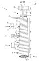
Fig. 1 zeigt eine Vorrichtung 1 zum Herstellen eines kanallosen, hülsenförmigen Drucktuchs 100 in einem kontinuierlichen Verfahren. In diesem Zusammenhang deutet der Begriff "kontinuierliches Verfahren" an, dass das Verfahren ein endloses, hülsenförmiges Drucktuchs von unbestimmter axialer Länge erzeugt.1 shows a device 1 for producing a channelless,
Vorrichtung 1 umfasst eine Dreh- und Weiterbeförderungseinrichtung 11 zum kontinuierlichen Bewegen des Drucktuchs 100 von rechts nach links in Fig. 1. Die Einrichtung 11 weist einen Antriebsabschnitt 300 auf, der bewegbare Stäbe 201, 202, 203, 204, 205, 206, etc. kontinuierlich dreht und weiterbefördert, wie unter Bezug auf Fig. 2a und Fig. 2b nachfolgend beschrieben.Apparatus 1 comprises a turning and further conveying
In einer ersten Station 110 wird ein Band 32, das vorzugsweise aus Stahl besteht und zwei überlappende Stücke Band aufweisen kann, der Vorrichtung 11 zugeführt, die das Band so abwickelt, dass eine Trägerhülse 33 gebildet wird.In a
An einer zweiten Station 120 umfasst eine zu Vorrichtung 1 gehörende erste Bandgießvorrichtung 20 zum Herstellen einer kompressiblen Schicht eine Urethanzufuhr 21 und eine Blaseinrichtung 22. Die Urethanzufuhr 21 kann eine Vielzahl separater Abschnitte umfassen, beispielsweise einen Isocyanat-Abschnitt, einen Vulkanisationsabschnitt und eine Mischkammer, sowie weitere Materialabschnitte. Urethan aus der Zufuhr 21 wird durch die Blaseinrichtung 22 in der Mischkammer geschäumt und tritt an einer Düse 23 mit einem Endmundstück aus. Das geschäumte Urethan wird auf diese Weise auf die Trägerhülse 33 aufgetragen, um eine kompressible Schicht 34 zu bilden, die zur Veranschaulichung mit den aufgetragenen flüssigen Bändern in Form einer Spirale gezeigt ist. In Wirklichkeit fließen die aufgetragenen flüssigen Bänder zusammen und werden hart, um eine nahtlose, kanallose kompressible Schicht 34 zu bilden.At a
Eine Rakel oder ein Schabmesser 55 kann die Urethan-Schicht 34 berühren, und eine Schleifvorrichtung 56 kann die Schicht 34 glätten, um Unvollkommenheiten, wie beispielsweise Wellungen, in der Schicht 34 zu reduzieren.A squeegee or
Über diese kompressible Schicht 34 wird von einer zweiten Bandgießvorrichtung 30 der Vorrichtung 1 eine Verstärkungsschicht 42 in Abschnitt 130 einer dritten Station aufgetragen. Die Bandgießvorrichtung 30 kann eine Urethanzufuhr 31 und eine Düse 36 zum Auftragen des Urethan aufweisen. Der Härteprüfwert des Urethan beträgt vorzugsweise etwa 100 Shore A. Wiederum fließt das aufgetragene Urethan zusammen und wird hart, um eine nahtlose und kanallose Verstärkungsschicht 42 zu bilden. Zum Reduzieren von Unvollkommenheiten in der Schicht 42 können ein Schabmesser 57 und eine Schleifvorrichtung 58 verwendet werden.Via this
Eine dritte Bandgießvorrichtung 40, die der Vorrichtung 30 ähnelt, schafft ein Band aus Urethan, um eine Druckschicht 45 über der Verstärkungsschicht 42 zu bilden. Das Urethan der Druckschicht weist vorzugsweise einen Härteprüfwert von etwa 60 Shore A auf. Die aufgetragene Druckschicht bildet beim Härten eine nahtlose und kanallose Schicht. Falls gewünscht, können ein Schabmesser 51 und eine Schleifvorrichtung 50 zum Korrigieren oder Reduzieren von Unvollkommenheiten, wie beispielsweise Wellungen, in der Druckschicht 45 verwendet werden.A third
Sobald die Druckschicht 45 fertig ist, setzt das Drucktuch seine Bewegung in Richtung der Pfeile 5 fort, bis eine gewünschte Länge erreicht ist und das Drucktuch durchschnitten wird, beispielsweise von einem umlaufenden Messer oder einer umlaufenden Säge.Once the
In Abschnitt 110 ist die Hülse von den Stäben 201-210 (siehe Fig. 2a und Fig. 2b) gehalten, und kann in den Abschnitten 120, 130 und 140 durch Innenlager getragen werden.In
Fig. 2a ist eine nähere Ansicht der Arbeitsweise der Stäbe 201, 202, 203, 204, 205, 206, 207, die in die Richtung 218 drehen. Wenn sich die Stäbe drehen, werden gleichzeitig neun der zehn Stäbe in Richtung 5 weiterbewegt. Wenn ein Stab eine axial entfernteste Stelle in Richtung 5 erreicht, wird dieser in entgegengesetzter Richtung 5 zurückgeschoben, wie für Stab 201 in Fig. 2a gezeigt. Diese Bewegung behindert die Weiterbeförderung der Hülse in Richtung 5 nicht, da die anderen neun Stäbe die Hülse weiterhin in Richtung 5 schieben. Sobald der Stab 201 zurückgeschoben ist, beginnt sich dieser wieder in Richtung 5 zu bewegen.FIG. 2a is a closer view of the operation of
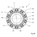
Fig. 2b zeigt eine Querschnittsansicht der Stäbe 201, 202, 203, 204, 205, 206, 207, 208, 209 und 210 zusammen mit der Antriebsvorrichtung 300, welche die Stäbe dreht und weiterbefördert, zum Beispiel durch Lager 260.2b shows a cross-sectional view of the
Fig. 3 zeigt eine alternative Ausführung, bei der die Hülse von einer Transporteinrichtung 400 durch drei umlaufende Bandgießvorrichtungen 220, 230, 240 transportiert wird, welche jeweils die kompressible Schicht, die Verstärkungsschicht bzw. die Druckschicht auftragen. Die Schichten können aus gleichartigen Materialien wie die in Fig. 1 gezeigten Schichten 34, 42 und 45 sein.Fig. 3 shows an alternative embodiment in which the sleeve is transported by a
Fig. 4 zeigt eine Querschnittsansicht des Drucktuchs 100 mit der als Trägerhülse ausgebildeten Hülse 33, der kompressiblen Schicht 34, der Verstärkungsschicht 42 und der Druckschicht 45.4 shows a cross-sectional view of the
Wie hier verwendet, bezieht sich der Begriff "kompressible Schicht" auf ein polymeres Material, das durch eines der bekannten Verfahren kompressibel gemacht wurde, wozu zum Beispiel auch die Verwendung von Mikrokugeln, Treibmitteln, Schaumbildnern oder Auswaschen zählen. Beispiele dieser Materialien sind beispielsweise in der US 5,768,990, US 5,553,541, US 5,440,981, US 5,429,048, US 5,323,702 und US 5,304,267 offenbart.As used herein, the term "compressible layer" refers to a polymeric material which has been made compressible by any of the known processes, including, for example, the use of microspheres, blowing agents, foaming agents or leaching. Examples of these materials are disclosed, for example, in US 5,768,990, US 5,553,541, US 5,440,981, US 5,429,048, US 5,323,702 and US 5,304,267.
Wie hierin verwendet, bezieht sich der Begriff Druckschicht bzw. elastomeres Druckbitdübertragendes Material auf ein polymeres Material wie Urethan, das sich zum Übertragen eines Bildes von einer Offsetdruckplatte oder einem anderen Druckbildträger auf ein Rollen- oder Bogenmaterial in einer Druckqualität eignet, die den Anforderungen der jeweiligen Druckanwendung entspricht.As used herein, the term print layer or elastomeric print material refers to a polymeric material, such as urethane, suitable for transferring an image from an offset printing plate or other print substrate to a roll or sheet material of a print quality meeting the requirements of each Pressure application corresponds.
Wenngleich die bevorzugten Ausführungen des im kontinuierlichen Verfahren hergestellten Offset-Drucktuchs gemäß der vorliegenden Erfindung hier so dargestellt wurden, dass sie eine kompressible Schicht, eine Verstärkungsschicht und eine Druckschicht umfassen, ist davon auszugehen, dass in dem Fall, dass dies für eine bestimmte Anwendung erforderlich ist, das Drucktuch auch eine Grundaufbauschicht zwischen der Trägerhülse 33 und der kompressiblen Schicht 34 beinhalten kann.While the preferred embodiments of the offset blanket of the present invention prepared in the continuous process have been illustrated herein to include a compressible layer, a reinforcing layer and a print layer, it will be understood that in the event that this is required for a particular application is that the blanket may also include a base coat layer between the
Zusätzlich ist davon auszugehen, dass - wenngleich das erfindungsgemäße Drucktuch vorzugsweise eine kompressible, eine Verstärkungs- und eine Druckschicht umfasst - es auch möglich ist, Drucktücher mit weniger oder mit zusätzlichen Schichten herzustellen. So kann ein erfindungsgemäßes Drucktuch, wenn dies für eine bestimmte Anwendung sinnvoll ist, eine Trägerhülse und eine Druckschicht, oder eine Trägerhülse, eine kompressible Schicht und eine Druckschicht umfassen. Darüber hinaus ist davon auszugehen, dass ein erfindungsgemäßes Drucktuch auch mehrere kompressible Schichten, mehrere Aufbauschichten oder mehrere Verstärkungsschichten umfassen könnte.In addition, although the blanket of the invention preferably comprises a compressible, a reinforcing and a printing layer, it is to be understood that it is also possible to make blankets with fewer or with additional layers. Thus, a printing blanket according to the invention, if this is sensible for a specific application, may comprise a carrier sleeve and a printing layer, or a carrier sleeve, a compressible layer and a printing layer. In addition, it is to be assumed that a printing blanket according to the invention also comprises a plurality of compressible layers, could comprise multiple build-up layers or multiple reinforcement layers.
Wenngleich die Verstärkungsschicht vorzugsweise aus Urethan gebildet wird, kann die Verstärkungsschicht ebenso aus Wickelgewebe oder Kunststoffband, Schnur oder Faden um das Arbeitsstück gebildet werden. Auch können Querspritz-Extruderköpfe oder Streifen zum Bilden einiger der Schichten verwendet werden, die nicht durch Bandgießen hergestellt werden.Although the reinforcing layer is preferably formed from urethane, the reinforcing layer may also be formed of wrapping fabric or plastic tape, string or thread around the workpiece. Also, cross-spray extruder heads or strips can be used to form some of the layers that are not made by tape casting.
Die Temperatur des fließfähigen Materials kann von den jeweiligen Bandgießvorrichtungen kontrolliert werden. Auch können die Düsen Mundstücke aufweisen, deren Form geändert werden kann, um eine Veränderung der Bandabmessungen zu bewirken. Vorzugsweise sind die Temperatur und die Form der Düsen so beschaffen, dass ein stetiger Strom von fließfähigem Material auf das Substrat fließt. Fließgeschwindigkeit, Temperatur, Düsenform und Drehgeschwindigkeit des Substrats können verändert werden, um die gewünschten Eigenschaften für die unterschiedlichen Schichten zu erhalten, zum Beispiel die Dicke der Schicht.The temperature of the flowable material can be controlled by the respective belt casting machines. Also, the nozzles may have mouthpieces whose shape may be changed to effect a change in tape dimensions. Preferably, the temperature and shape of the nozzles are such that a steady stream of flowable material flows onto the substrate. Flow rate, temperature, nozzle shape and rotational speed of the substrate can be varied to obtain the desired properties for the different layers, for example the thickness of the layer.
- 11
- Vorrichtungcontraption
- 55
- Richtungspfeiledirectional arrows
- 1111
- Dreh- und WeiterbeförderungseinrichtungRotary and onward transport facility
- 2020
- erste Bandgießvorrichtungfirst strip casting device
- 2121
- UrethanzufuhrUrethanzufuhr
- 2222
- Blaseinrichtungblower
- 2323
- Düsejet
- 3030
- zweite Bandgießvorrichtungsecond strip casting device
- 3131
- UrethanzufuhrUrethanzufuhr
- 3232
- Bandtape
- 3333
- Trägerhülsesupport sleeve
- 3434
- kompressible Schichtcompressible layer
- 3636
- Düsejet
- 4040
- dritte Bandgießvorrichtungthird strip casting device
- 4242
- Verstärkungsschichtreinforcing layer
- 4545
- Druckschichtprint layer
- 51, 55, 5751, 55, 57
- SchabmesserSchabmesser
- 50, 56, 5850, 56, 58
- Schleifvorrichtunggrinder
- 100100
- Drucktuchblanket
- 110110
- erste Stationfirst stop
- 120120
- zweite Stationsecond station
- 130130
- dritte Stationthird station
- 201...210201 ... 210
- Stäberods
- 218218
- Richtungspfeilarrow
- 220,230,240220,230,240
- BandgießvorrichtungenBandgießvorrichtungen
- 260260
- Lagercamp
- 300300
- Antriebsabschnittdriving section
- 400400
- Transporteinrichtungtransport means
Claims (32)
- Device for the production of a sleeve-type printing blanket with:a sleeve transport means (11) for moving a support sleeve (33),characterised by
at least one continuous casting device (20) applying a flowable material and having a nozzle (23), through which the flowable material flows, wherein the applied flowable material forms a layer (34; 42; 45) arranged over the support sleeve (33),
and a device for cutting through the sleeve-type printing blanket when a desired length is reached. - Device according to Claim 1, characterised in that the at least one continuous casting device (20) comprises a continuous casting device for the production of a compressible layer (34), which has a first feed region (21) for a flowable material and a compressibility generating means.
- Device according to Claim 2, characterised in that the compressibility generating means is a foaming agent.
- Device according to Claim 2, characterised in that the at least one continuous casting device (40) comprises a continuous casting device (40) for the production of a printing layer (45).
- Device according to Claim 2, characterised in that the at least one continuous casting device (20) comprises a continuous casting device (30) for the production of a reinforcing layer (42) and a continuous casting device (40) for the production of a printing layer (45).
- Device according to one of the preceding claims, characterised in that the at least one continuous casting device (20) has a single nozzle (23), through which the flowable material flows.
- Device according to one of the preceding claims, characterised in that the at least one continuous casting device (20) is fixed in position, and the sleeve transport means is a transporting and rotating means (11).
- Device according to Claim 7, characterised in that the support sleeve (33) is a continuous sleeve formed from a metal strip.
- Device according to one of Claims 1 to 6, characterised in that the at least one continuous casting device (20) is rotatable around the sleeve (33).
- Device according to one of the preceding claims, characterised in that the flowable material is a self-curing polymer.
- Device according to Claim 10, characterised in that the self-curing polymer is urethane.
- Device according to Claim 10, characterised in that the self-curing polymer is rubber, which cures as room temperature.
- Device according to one of the preceding claims, which additional comprises a grinding station (56), which is connected behind the at least one continuous casting device (20).
- Process for the production of a sleeve-type printing blanket, wherein a support sleeve is transported in a first direction, characterised by
continuous casting of a compressible layer (34), a reinforcing layer (42) and/or a printing layer (45) around the support sleeve (33) using at least one continuous casting device (20) applying a flowable material and having a nozzle (23), through which the flowable material flows, while the support sleeve (33) moves further, and additionally including the cutting of the sleeve (33) to a desired length. - Process according to Claim 14, which additionally includes rotation of the support sleeve (33) during the step of further transport.
- Process according to Claim 14, characterised in that the step of continuous casting includes rotation of a continuous casting device (20) around the sleeve (33) while the support sleeve (33) moves further.
- Process according to one of Claims 14 to 16, characterised in that the compressible layer (34), the reinforcing layer (42) or the printing layer (45) is made of urethane.
- Process according to Claim 17, which comprises the following process steps, characterised in that the compressible layer (34) of urethane is applied to the support sleeve (33); and that the printing layer (45) of urethane is applied over the compressible layer (34).
- Process according to Claim 17 or 18, which additionally includes the application of the reinforcing layer (42) of urethane over the compressible layer (34).
- Process according to one of Claims 14 to 16, characterised in that the compressible layer (34), the reinforcing layer (42) or the printing layer (45) is made from a self-curing polymer.
- Process according to one of Claims 14 to 20, characterised in that the support sleeve (33) is formed continuously.
- Process according to one of Claims 14 to 21, which additionally includes grinding of the compressible layer (34), the reinforcing layer (42) and/or the printing layer (45).
- Process according to one of Claims 14 to 22, characterised in that the printing blanket (100) is formed continuously.
- Sleeve-type printing blanket for offset printing with:a support sleeve (33); a compressible layer (34) arranged over the support sleeve (33) and a printing layer (45) arranged over the compressible layer (34),characterised in that the compressible layer (34) and/or the printing layer (45) is made from urethane, and that the printing blanket is produced by means of the process according to one of Claims 14 to 23.
- Printing blanket according to Claim 24, which additionally comprises a reinforcing layer (42) arranged between the compressible layer (34) and the printing layer (45).
- Printing blanket according to Claim 25, characterised in that the reinforcing layer (42) is made from urethane.
- Printing blanket according to Claim 25 or 26, characterised in that the reinforcing layer (42) has a hardness test value of more than 80 Shore A.
- Printing blanket according to one of Claims 25 to 27, characterised in that the reinforcing layer (42) is thinner than the compressible layer.
- Printing blanket according to Claim 28, characterised in that the printing layer (45) is produced from urethane with a hardness test value below 80 Shore A.
- Printing blanket according to one of Claims 24 to 29, characterised in that the support sleeve is produced from a band (32) wound in a spiral shape.
- Sleeve-type printing blanket for offset printing with:a support sleeve (33); a compressible layer (34) arranged over the support sleeve (33) and a printing layer (45) arranged over the compressible layer (34), characterised in that the compressible layer (34) and/or the printing layer (45) is made from a self-curing polymer, and that the printing blanket is produced by means of a process according to Claim 20.
- Printing blanket according to Claim 31, characterised in that the self-curing polymer is rubber, which cures as room temperature.
Applications Claiming Priority (2)
| Application Number | Priority Date | Filing Date | Title |
|---|---|---|---|
| US716696 | 2000-11-20 | ||
| US09/716,696 US6615721B1 (en) | 2000-11-20 | 2000-11-20 | Method and device for manufacturing a tubular lithographic printing blanket |
Publications (3)
| Publication Number | Publication Date |
|---|---|
| EP1208996A2 EP1208996A2 (en) | 2002-05-29 |
| EP1208996A3 EP1208996A3 (en) | 2004-07-28 |
| EP1208996B1 true EP1208996B1 (en) | 2006-06-28 |
Family
ID=24879053
Family Applications (1)
| Application Number | Title | Priority Date | Filing Date |
|---|---|---|---|
| EP01126529A Expired - Lifetime EP1208996B1 (en) | 2000-11-20 | 2001-11-14 | Apparatus for the production of sleeve type printing blankets |
Country Status (7)
| Country | Link |
|---|---|
| US (1) | US6615721B1 (en) |
| EP (1) | EP1208996B1 (en) |
| JP (1) | JP4593849B2 (en) |
| CN (1) | CN1355099A (en) |
| AT (1) | ATE331634T1 (en) |
| DE (2) | DE10155681A1 (en) |
| HK (1) | HK1047262A1 (en) |
Families Citing this family (14)
| Publication number | Priority date | Publication date | Assignee | Title |
|---|---|---|---|---|
| US20020119323A1 (en) * | 2000-12-15 | 2002-08-29 | Johann Weinert | Compressible polyurethane layer and process for the preparation therof |
| US6779451B2 (en) | 2001-06-27 | 2004-08-24 | Heidelberger Druckmaschinen Ag | Flexible tubular printing blanket |
| US6874232B2 (en) * | 2003-05-21 | 2005-04-05 | Stowe Woodward, Llc | Method for forming cover for industrial roll |
| US10287731B2 (en) * | 2005-11-08 | 2019-05-14 | Stowe Woodward Licensco Llc | Abrasion-resistant rubber roll cover with polyurethane coating |
| US20080034998A1 (en) * | 2006-08-08 | 2008-02-14 | Byers Joseph L | Method of making a printing blanket or sleeve including cast polyurethane layers |
| US20080038025A1 (en) * | 2006-08-14 | 2008-02-14 | Eastman Kodak Company | Intermediate transfer member |
| US7976658B2 (en) * | 2006-08-14 | 2011-07-12 | Eastman Kodak Company | Method of manufacturing a low cost intermediate transfer member |
| US20080070042A1 (en) * | 2006-09-20 | 2008-03-20 | Day International, Inc. | Printing blanket or sleeve including thermoplastic polyurethane or thermoplastic polyurethane alloy layers |
| FR2922154B1 (en) * | 2007-10-11 | 2010-01-15 | Goss Int Montataire Sa | PRINTING UNIT AND ITS USE |
| US8409698B2 (en) * | 2007-11-30 | 2013-04-02 | Day International, Inc. | Image transfer product including a thin printing surface layer |
| US20090193991A1 (en) * | 2008-02-04 | 2009-08-06 | Felice Rossini | Blanket sleeve and cylinder and method of making same |
| US20100307356A1 (en) * | 2008-02-04 | 2010-12-09 | Felice Rossini | Bridged sleeve/cylinder and method of making same for web offset printing machines |
| DE102017128894B4 (en) * | 2017-12-05 | 2024-01-25 | Tampoprint Ag | Device and method for producing an endless belt as an intermediate printing carrier |
| KR102124156B1 (en) * | 2018-08-21 | 2020-06-17 | 김순호 | A Efficient Offsetpress Blanket Method System And A Offsetpress With The Blanket Repair Method System Thereof |
Family Cites Families (15)
| Publication number | Priority date | Publication date | Assignee | Title |
|---|---|---|---|---|
| DE3908999A1 (en) * | 1989-03-18 | 1990-09-20 | Roland Man Druckmasch | CARRIER SLEEVE, ESPECIALLY FOR THE OFFSET CYLINDER OF A ROTATION PRINTING MACHINE |
| US5553541A (en) | 1989-10-05 | 1996-09-10 | Heidelberg Harris Inc | Gapless tubular printing blanket |
| US5429048A (en) | 1989-10-05 | 1995-07-04 | Gaffney; John M. | Offset lithographic printing press |
| US5352507A (en) * | 1991-04-08 | 1994-10-04 | W. R. Grace & Co.-Conn. | Seamless multilayer printing blanket |
| CA2068629C (en) | 1991-05-14 | 1996-05-07 | James B. Vrotacoe | Gapless tubular printing blanket |
| DE4123920C2 (en) * | 1991-07-19 | 1994-04-14 | Bayer Ag | Method and device for manufacturing coiled tubes |
| US5206992A (en) * | 1992-06-12 | 1993-05-04 | American Roller Company | Compressible roller |
| US5301610A (en) * | 1993-04-30 | 1994-04-12 | E. I. Du Pont De Nemours And Company | Method and apparatus for making spiral wound sleeves for printing cylinders and product thereof |
| US5544584A (en) * | 1994-12-09 | 1996-08-13 | Thompson Urethane Products | Process for producing polymer-covered flexographic printing sleeves |
| US5798019A (en) * | 1995-09-29 | 1998-08-25 | E. I. Du Pont De Nemours And Company | Methods and apparatus for forming cylindrical photosensitive elements |
| US5700343A (en) * | 1996-01-16 | 1997-12-23 | Reeves Brothers, Inc. | Preparation of cylindrical blanket by spreading of compressible layer |
| DE19720549A1 (en) | 1997-05-16 | 1998-11-19 | Heidelberger Druckmasch Ag | Process for the production of cylindrical coating substrates |
| DE19720551A1 (en) * | 1997-05-16 | 1998-11-19 | Heidelberger Druckmasch Ag | Base carrier sleeve for rotary printing machines |
| JP2000118164A (en) * | 1998-10-14 | 2000-04-25 | Kinyosha Co Ltd | Blanket for offset printing and its manufacture |
| US6257140B1 (en) * | 1999-12-27 | 2001-07-10 | Heidelberger Druckmaschinen Ag | Continuous process gapless tubular lithographic printing blanket |
-
2000
- 2000-11-20 US US09/716,696 patent/US6615721B1/en not_active Expired - Fee Related
-
2001
- 2001-10-26 CN CN01134301A patent/CN1355099A/en active Pending
- 2001-11-13 DE DE10155681A patent/DE10155681A1/en not_active Withdrawn
- 2001-11-14 AT AT01126529T patent/ATE331634T1/en not_active IP Right Cessation
- 2001-11-14 DE DE50110319T patent/DE50110319D1/en not_active Expired - Lifetime
- 2001-11-14 EP EP01126529A patent/EP1208996B1/en not_active Expired - Lifetime
- 2001-11-16 JP JP2001352120A patent/JP4593849B2/en not_active Expired - Fee Related
-
2002
- 2002-12-12 HK HK02109016.9A patent/HK1047262A1/en unknown
Also Published As
| Publication number | Publication date |
|---|---|
| EP1208996A2 (en) | 2002-05-29 |
| US6615721B1 (en) | 2003-09-09 |
| DE50110319D1 (en) | 2006-08-10 |
| JP4593849B2 (en) | 2010-12-08 |
| CN1355099A (en) | 2002-06-26 |
| EP1208996A3 (en) | 2004-07-28 |
| ATE331634T1 (en) | 2006-07-15 |
| DE10155681A1 (en) | 2002-07-11 |
| JP2002200860A (en) | 2002-07-16 |
| HK1047262A1 (en) | 2003-02-14 |
Similar Documents
| Publication | Publication Date | Title |
|---|---|---|
| EP1208996B1 (en) | Apparatus for the production of sleeve type printing blankets | |
| EP0614838B1 (en) | Exchangeable press bushing | |
| DE69916709T2 (en) | Method and device for applying rubber materials for tire building parts | |
| EP0166245A2 (en) | Method and apparatus for continuously forming tubular hollow bodies, in particular hoses, tubes and inner liners for them, from a liquid material, such as a reaction mixture or a melt | |
| DD263261A5 (en) | METHOD FOR MANUFACTURING A FIRST VEHICLE RADIAL TIRE PREPARATION | |
| EP0897796B1 (en) | Method of manufacturing a screen printing jig and apparatus therefor | |
| EP1112860B1 (en) | Method for continuous preparation of tubular, preferably seamless rubber printing blankets for offset printing maschines | |
| EP1275520B1 (en) | Process of production of a flexible rubber blanket sleeve | |
| CH424696A (en) | Printing blanket for printing machines | |
| DE10225541A1 (en) | Method and device for producing a tubular rubber blanket | |
| DE60222839T2 (en) | A method of manufacturing a pneumatic tire comprising a cord reinforced layer | |
| DD151132A5 (en) | METHOD AND DEVICE FOR FORMING INNER LINE FOR THE PRODUCTION OF VEHICLE TIRES | |
| DE2355847A1 (en) | METHOD AND DEVICE FOR THE PRODUCTION OF FLEXIBLE TUBES WITH A WIRE INSERT | |
| DE2109809A1 (en) | Tape builder | |
| DE60318956T2 (en) | METHOD AND DEVICE FOR APPLYING A COATING TO A BODY ROTATING ONE AXLE | |
| EP0400573A1 (en) | Method and apparatus for the manufacture of an endless belt coated on both sides | |
| DE19931002A1 (en) | Cylinder diameter adjustment has casing component with aluminum or steel plate and top elastic material, clamp and fastening | |
| EP1316423A1 (en) | Engraved roller and method for its production and reprocessing | |
| DE2834246A1 (en) | Perforating machine for strips of material - has roller with perforating tools, and backing rollers applying pressure | |
| EP2050560A1 (en) | Device for applying strips of material to a green tyre or an expansion drum | |
| EP1943090A1 (en) | Device for guiding and pressing rubber for constructing a tyre construction layer | |
| EP0400281A2 (en) | Device for continuously jacketing cylindrical workpieces with elastic material | |
| DE60026573T2 (en) | METHOD AND DEVICE FOR AUTOMATIC SEPARATION OF SUPPORT WEAVE FROM RUBBER BAND | |
| EP2707203A1 (en) | Device having a single roll roller die system | |
| DE10046559A1 (en) | Printing plate mounting system |
Legal Events
| Date | Code | Title | Description |
|---|---|---|---|
| PUAI | Public reference made under article 153(3) epc to a published international application that has entered the european phase |
Free format text: ORIGINAL CODE: 0009012 |
|
| AK | Designated contracting states |
Kind code of ref document: A2 Designated state(s): AT BE CH CY DE DK ES FI FR GB GR IE IT LI LU MC NL PT SE TR |
|
| AX | Request for extension of the european patent |
Free format text: AL;LT;LV;MK;RO;SI |
|
| RIC1 | Information provided on ipc code assigned before grant |
Ipc: 7B 41N 7/00 A Ipc: 7B 41N 10/02 B |
|
| 17P | Request for examination filed |
Effective date: 20040407 |
|
| PUAL | Search report despatched |
Free format text: ORIGINAL CODE: 0009013 |
|
| AK | Designated contracting states |
Kind code of ref document: A3 Designated state(s): AT BE CH CY DE DK ES FI FR GB GR IE IT LI LU MC NL PT SE TR |
|
| AX | Request for extension of the european patent |
Extension state: AL LT LV MK RO SI |
|
| RAP1 | Party data changed (applicant data changed or rights of an application transferred) |
Owner name: GOSS INTERNATIONAL AMERICAS, INC. |
|
| AKX | Designation fees paid |
Designated state(s): AT BE CH CY DE DK ES FI FR GB GR IE IT LI LU MC NL PT SE TR |
|
| GRAP | Despatch of communication of intention to grant a patent |
Free format text: ORIGINAL CODE: EPIDOSNIGR1 |
|
| GRAC | Information related to communication of intention to grant a patent modified |
Free format text: ORIGINAL CODE: EPIDOSCIGR1 |
|
| GRAS | Grant fee paid |
Free format text: ORIGINAL CODE: EPIDOSNIGR3 |
|
| GRAA | (expected) grant |
Free format text: ORIGINAL CODE: 0009210 |
|
| AK | Designated contracting states |
Kind code of ref document: B1 Designated state(s): AT BE CH CY DE DK ES FI FR GB GR IE IT LI LU MC NL PT SE TR |
|
| PG25 | Lapsed in a contracting state [announced via postgrant information from national office to epo] |
Ref country code: IT Free format text: LAPSE BECAUSE OF FAILURE TO SUBMIT A TRANSLATION OF THE DESCRIPTION OR TO PAY THE FEE WITHIN THE PRESCRIBED TIME-LIMIT;WARNING: LAPSES OF ITALIAN PATENTS WITH EFFECTIVE DATE BEFORE 2007 MAY HAVE OCCURRED AT ANY TIME BEFORE 2007. THE CORRECT EFFECTIVE DATE MAY BE DIFFERENT FROM THE ONE RECORDED. Effective date: 20060628 Ref country code: FI Free format text: LAPSE BECAUSE OF FAILURE TO SUBMIT A TRANSLATION OF THE DESCRIPTION OR TO PAY THE FEE WITHIN THE PRESCRIBED TIME-LIMIT Effective date: 20060628 Ref country code: IE Free format text: LAPSE BECAUSE OF FAILURE TO SUBMIT A TRANSLATION OF THE DESCRIPTION OR TO PAY THE FEE WITHIN THE PRESCRIBED TIME-LIMIT Effective date: 20060628 Ref country code: NL Free format text: LAPSE BECAUSE OF FAILURE TO SUBMIT A TRANSLATION OF THE DESCRIPTION OR TO PAY THE FEE WITHIN THE PRESCRIBED TIME-LIMIT Effective date: 20060628 |
|
| REG | Reference to a national code |
Ref country code: GB Ref legal event code: FG4D Free format text: NOT ENGLISH |
|
| REG | Reference to a national code |
Ref country code: CH Ref legal event code: EP |
|
| REG | Reference to a national code |
Ref country code: CH Ref legal event code: NV Representative=s name: KIRKER & CIE SA |
|
| GBT | Gb: translation of ep patent filed (gb section 77(6)(a)/1977) |
Effective date: 20060711 |
|
| REG | Reference to a national code |
Ref country code: IE Ref legal event code: FG4D Free format text: LANGUAGE OF EP DOCUMENT: GERMAN |
|
| REF | Corresponds to: |
Ref document number: 50110319 Country of ref document: DE Date of ref document: 20060810 Kind code of ref document: P |
|
| PG25 | Lapsed in a contracting state [announced via postgrant information from national office to epo] |
Ref country code: DK Free format text: LAPSE BECAUSE OF FAILURE TO SUBMIT A TRANSLATION OF THE DESCRIPTION OR TO PAY THE FEE WITHIN THE PRESCRIBED TIME-LIMIT Effective date: 20060928 Ref country code: SE Free format text: LAPSE BECAUSE OF FAILURE TO SUBMIT A TRANSLATION OF THE DESCRIPTION OR TO PAY THE FEE WITHIN THE PRESCRIBED TIME-LIMIT Effective date: 20060928 |
|
| PG25 | Lapsed in a contracting state [announced via postgrant information from national office to epo] |
Ref country code: ES Free format text: LAPSE BECAUSE OF FAILURE TO SUBMIT A TRANSLATION OF THE DESCRIPTION OR TO PAY THE FEE WITHIN THE PRESCRIBED TIME-LIMIT Effective date: 20061009 |
|
| PG25 | Lapsed in a contracting state [announced via postgrant information from national office to epo] |
Ref country code: PT Free format text: LAPSE BECAUSE OF FAILURE TO SUBMIT A TRANSLATION OF THE DESCRIPTION OR TO PAY THE FEE WITHIN THE PRESCRIBED TIME-LIMIT Effective date: 20061128 |
|
| PG25 | Lapsed in a contracting state [announced via postgrant information from national office to epo] |
Ref country code: BE Free format text: LAPSE BECAUSE OF NON-PAYMENT OF DUE FEES Effective date: 20061130 Ref country code: MC Free format text: LAPSE BECAUSE OF NON-PAYMENT OF DUE FEES Effective date: 20061130 |
|
| NLV1 | Nl: lapsed or annulled due to failure to fulfill the requirements of art. 29p and 29m of the patents act | ||
| ET | Fr: translation filed | ||
| REG | Reference to a national code |
Ref country code: IE Ref legal event code: FD4D |
|
| PLBE | No opposition filed within time limit |
Free format text: ORIGINAL CODE: 0009261 |
|
| STAA | Information on the status of an ep patent application or granted ep patent |
Free format text: STATUS: NO OPPOSITION FILED WITHIN TIME LIMIT |
|
| 26N | No opposition filed |
Effective date: 20070329 |
|
| BERE | Be: lapsed |
Owner name: GOSS INTERNATIONAL AMERICAS, INC. Effective date: 20061130 |
|
| PG25 | Lapsed in a contracting state [announced via postgrant information from national office to epo] |
Ref country code: AT Free format text: LAPSE BECAUSE OF NON-PAYMENT OF DUE FEES Effective date: 20061114 |
|
| PG25 | Lapsed in a contracting state [announced via postgrant information from national office to epo] |
Ref country code: GR Free format text: LAPSE BECAUSE OF FAILURE TO SUBMIT A TRANSLATION OF THE DESCRIPTION OR TO PAY THE FEE WITHIN THE PRESCRIBED TIME-LIMIT Effective date: 20060929 |
|
| PG25 | Lapsed in a contracting state [announced via postgrant information from national office to epo] |
Ref country code: TR Free format text: LAPSE BECAUSE OF FAILURE TO SUBMIT A TRANSLATION OF THE DESCRIPTION OR TO PAY THE FEE WITHIN THE PRESCRIBED TIME-LIMIT Effective date: 20060628 Ref country code: LU Free format text: LAPSE BECAUSE OF NON-PAYMENT OF DUE FEES Effective date: 20061114 |
|
| PG25 | Lapsed in a contracting state [announced via postgrant information from national office to epo] |
Ref country code: CY Free format text: LAPSE BECAUSE OF FAILURE TO SUBMIT A TRANSLATION OF THE DESCRIPTION OR TO PAY THE FEE WITHIN THE PRESCRIBED TIME-LIMIT Effective date: 20060628 |
|
| PGFP | Annual fee paid to national office [announced via postgrant information from national office to epo] |
Ref country code: FR Payment date: 20101202 Year of fee payment: 10 |
|
| PGFP | Annual fee paid to national office [announced via postgrant information from national office to epo] |
Ref country code: CH Payment date: 20101124 Year of fee payment: 10 Ref country code: DE Payment date: 20101126 Year of fee payment: 10 |
|
| PGFP | Annual fee paid to national office [announced via postgrant information from national office to epo] |
Ref country code: GB Payment date: 20101124 Year of fee payment: 10 |
|
| REG | Reference to a national code |
Ref country code: CH Ref legal event code: PL |
|
| GBPC | Gb: european patent ceased through non-payment of renewal fee |
Effective date: 20111114 |
|
| PG25 | Lapsed in a contracting state [announced via postgrant information from national office to epo] |
Ref country code: LI Free format text: LAPSE BECAUSE OF NON-PAYMENT OF DUE FEES Effective date: 20111130 Ref country code: CH Free format text: LAPSE BECAUSE OF NON-PAYMENT OF DUE FEES Effective date: 20111130 |
|
| REG | Reference to a national code |
Ref country code: FR Ref legal event code: ST Effective date: 20120731 |
|
| REG | Reference to a national code |
Ref country code: DE Ref legal event code: R119 Ref document number: 50110319 Country of ref document: DE Effective date: 20120601 |
|
| PG25 | Lapsed in a contracting state [announced via postgrant information from national office to epo] |
Ref country code: GB Free format text: LAPSE BECAUSE OF NON-PAYMENT OF DUE FEES Effective date: 20111114 |
|
| PG25 | Lapsed in a contracting state [announced via postgrant information from national office to epo] |
Ref country code: FR Free format text: LAPSE BECAUSE OF NON-PAYMENT OF DUE FEES Effective date: 20111130 |
|
| PG25 | Lapsed in a contracting state [announced via postgrant information from national office to epo] |
Ref country code: DE Free format text: LAPSE BECAUSE OF NON-PAYMENT OF DUE FEES Effective date: 20120601 |