EP1208677B1 - Verfahren und vorrichtung zur sprache-über-ip unterstützung in einer netzwerkvermittlung - Google Patents
Verfahren und vorrichtung zur sprache-über-ip unterstützung in einer netzwerkvermittlung Download PDFInfo
- Publication number
- EP1208677B1 EP1208677B1 EP00959167A EP00959167A EP1208677B1 EP 1208677 B1 EP1208677 B1 EP 1208677B1 EP 00959167 A EP00959167 A EP 00959167A EP 00959167 A EP00959167 A EP 00959167A EP 1208677 B1 EP1208677 B1 EP 1208677B1
- Authority
- EP
- European Patent Office
- Prior art keywords
- packet
- port
- voip
- packets
- data
- Prior art date
- Legal status (The legal status is an assumption and is not a legal conclusion. Google has not performed a legal analysis and makes no representation as to the accuracy of the status listed.)
- Expired - Lifetime
Links
- 238000000034 method Methods 0.000 title claims abstract description 76
- 238000001914 filtration Methods 0.000 claims abstract description 96
- 238000004891 communication Methods 0.000 claims abstract description 43
- 230000009471 action Effects 0.000 claims description 56
- XUIMIQQOPSSXEZ-UHFFFAOYSA-N Silicon Chemical compound [Si] XUIMIQQOPSSXEZ-UHFFFAOYSA-N 0.000 claims description 8
- 229910052710 silicon Inorganic materials 0.000 claims description 8
- 239000010703 silicon Substances 0.000 claims description 8
- 230000008859 change Effects 0.000 claims description 4
- 239000000284 extract Substances 0.000 claims description 3
- 239000000758 substrate Substances 0.000 claims description 2
- 238000000605 extraction Methods 0.000 claims 1
- 230000008569 process Effects 0.000 abstract description 32
- 230000005540 biological transmission Effects 0.000 description 42
- 230000006870 function Effects 0.000 description 27
- 239000000872 buffer Substances 0.000 description 22
- 230000000903 blocking effect Effects 0.000 description 20
- 238000007726 management method Methods 0.000 description 19
- 238000012545 processing Methods 0.000 description 14
- 238000012546 transfer Methods 0.000 description 14
- 230000032683 aging Effects 0.000 description 13
- 230000001934 delay Effects 0.000 description 10
- 238000010586 diagram Methods 0.000 description 10
- 230000007246 mechanism Effects 0.000 description 9
- 238000003780 insertion Methods 0.000 description 8
- 230000037431 insertion Effects 0.000 description 8
- 238000010926 purge Methods 0.000 description 8
- 230000033001 locomotion Effects 0.000 description 6
- 241001522296 Erithacus rubecula Species 0.000 description 5
- 230000006835 compression Effects 0.000 description 5
- 238000007906 compression Methods 0.000 description 5
- 230000000694 effects Effects 0.000 description 5
- 238000005516 engineering process Methods 0.000 description 5
- 230000036961 partial effect Effects 0.000 description 5
- 230000001360 synchronised effect Effects 0.000 description 5
- 230000003139 buffering effect Effects 0.000 description 4
- 238000012217 deletion Methods 0.000 description 4
- 230000037430 deletion Effects 0.000 description 4
- 239000003550 marker Substances 0.000 description 4
- 230000006855 networking Effects 0.000 description 4
- 230000002829 reductive effect Effects 0.000 description 4
- 230000011664 signaling Effects 0.000 description 4
- 230000003068 static effect Effects 0.000 description 4
- 238000003491 array Methods 0.000 description 3
- 230000015556 catabolic process Effects 0.000 description 3
- 238000006731 degradation reaction Methods 0.000 description 3
- 230000003111 delayed effect Effects 0.000 description 3
- 238000013461 design Methods 0.000 description 3
- 235000003642 hunger Nutrition 0.000 description 3
- 238000013507 mapping Methods 0.000 description 3
- 238000012986 modification Methods 0.000 description 3
- 230000004048 modification Effects 0.000 description 3
- 238000001824 photoionisation detection Methods 0.000 description 3
- 238000012913 prioritisation Methods 0.000 description 3
- 230000037351 starvation Effects 0.000 description 3
- 239000000969 carrier Substances 0.000 description 2
- 230000007423 decrease Effects 0.000 description 2
- 230000008030 elimination Effects 0.000 description 2
- 238000003379 elimination reaction Methods 0.000 description 2
- 239000003292 glue Substances 0.000 description 2
- 230000002265 prevention Effects 0.000 description 2
- 230000004044 response Effects 0.000 description 2
- 230000002441 reversible effect Effects 0.000 description 2
- 101100258328 Neurospora crassa (strain ATCC 24698 / 74-OR23-1A / CBS 708.71 / DSM 1257 / FGSC 987) crc-2 gene Proteins 0.000 description 1
- 230000004913 activation Effects 0.000 description 1
- 230000002411 adverse Effects 0.000 description 1
- 230000003466 anti-cipated effect Effects 0.000 description 1
- 230000009286 beneficial effect Effects 0.000 description 1
- 230000008901 benefit Effects 0.000 description 1
- 238000004364 calculation method Methods 0.000 description 1
- 230000022131 cell cycle Effects 0.000 description 1
- 238000010276 construction Methods 0.000 description 1
- 239000013256 coordination polymer Substances 0.000 description 1
- 230000009849 deactivation Effects 0.000 description 1
- 230000003247 decreasing effect Effects 0.000 description 1
- 230000001419 dependent effect Effects 0.000 description 1
- 238000011161 development Methods 0.000 description 1
- 230000018109 developmental process Effects 0.000 description 1
- 239000000835 fiber Substances 0.000 description 1
- 230000012010 growth Effects 0.000 description 1
- 230000012447 hatching Effects 0.000 description 1
- 230000000977 initiatory effect Effects 0.000 description 1
- 238000012423 maintenance Methods 0.000 description 1
- 230000000873 masking effect Effects 0.000 description 1
- 239000011159 matrix material Substances 0.000 description 1
- 239000013307 optical fiber Substances 0.000 description 1
- 238000005457 optimization Methods 0.000 description 1
- 230000003252 repetitive effect Effects 0.000 description 1
- 238000012552 review Methods 0.000 description 1
- 230000011218 segmentation Effects 0.000 description 1
- 239000004065 semiconductor Substances 0.000 description 1
- 230000002123 temporal effect Effects 0.000 description 1
- 230000001960 triggered effect Effects 0.000 description 1
- XLYOFNOQVPJJNP-UHFFFAOYSA-N water Substances O XLYOFNOQVPJJNP-UHFFFAOYSA-N 0.000 description 1
Images


Classifications
-
- H—ELECTRICITY
- H04—ELECTRIC COMMUNICATION TECHNIQUE
- H04L—TRANSMISSION OF DIGITAL INFORMATION, e.g. TELEGRAPHIC COMMUNICATION
- H04L47/00—Traffic control in data switching networks
- H04L47/10—Flow control; Congestion control
-
- H—ELECTRICITY
- H04—ELECTRIC COMMUNICATION TECHNIQUE
- H04L—TRANSMISSION OF DIGITAL INFORMATION, e.g. TELEGRAPHIC COMMUNICATION
- H04L12/00—Data switching networks
- H04L12/54—Store-and-forward switching systems
- H04L12/56—Packet switching systems
- H04L12/5601—Transfer mode dependent, e.g. ATM
-
- H—ELECTRICITY
- H04—ELECTRIC COMMUNICATION TECHNIQUE
- H04L—TRANSMISSION OF DIGITAL INFORMATION, e.g. TELEGRAPHIC COMMUNICATION
- H04L12/00—Data switching networks
- H04L12/64—Hybrid switching systems
- H04L12/6402—Hybrid switching fabrics
-
- H—ELECTRICITY
- H04—ELECTRIC COMMUNICATION TECHNIQUE
- H04L—TRANSMISSION OF DIGITAL INFORMATION, e.g. TELEGRAPHIC COMMUNICATION
- H04L12/00—Data switching networks
- H04L12/64—Hybrid switching systems
- H04L12/6418—Hybrid transport
-
- H—ELECTRICITY
- H04—ELECTRIC COMMUNICATION TECHNIQUE
- H04L—TRANSMISSION OF DIGITAL INFORMATION, e.g. TELEGRAPHIC COMMUNICATION
- H04L47/00—Traffic control in data switching networks
- H04L47/10—Flow control; Congestion control
- H04L47/13—Flow control; Congestion control in a LAN segment, e.g. ring or bus
-
- H—ELECTRICITY
- H04—ELECTRIC COMMUNICATION TECHNIQUE
- H04L—TRANSMISSION OF DIGITAL INFORMATION, e.g. TELEGRAPHIC COMMUNICATION
- H04L47/00—Traffic control in data switching networks
- H04L47/10—Flow control; Congestion control
- H04L47/24—Traffic characterised by specific attributes, e.g. priority or QoS
- H04L47/2408—Traffic characterised by specific attributes, e.g. priority or QoS for supporting different services, e.g. a differentiated services [DiffServ] type of service
-
- H—ELECTRICITY
- H04—ELECTRIC COMMUNICATION TECHNIQUE
- H04L—TRANSMISSION OF DIGITAL INFORMATION, e.g. TELEGRAPHIC COMMUNICATION
- H04L47/00—Traffic control in data switching networks
- H04L47/10—Flow control; Congestion control
- H04L47/24—Traffic characterised by specific attributes, e.g. priority or QoS
- H04L47/2425—Traffic characterised by specific attributes, e.g. priority or QoS for supporting services specification, e.g. SLA
- H04L47/2433—Allocation of priorities to traffic types
-
- H—ELECTRICITY
- H04—ELECTRIC COMMUNICATION TECHNIQUE
- H04L—TRANSMISSION OF DIGITAL INFORMATION, e.g. TELEGRAPHIC COMMUNICATION
- H04L47/00—Traffic control in data switching networks
- H04L47/10—Flow control; Congestion control
- H04L47/24—Traffic characterised by specific attributes, e.g. priority or QoS
- H04L47/2441—Traffic characterised by specific attributes, e.g. priority or QoS relying on flow classification, e.g. using integrated services [IntServ]
-
- H—ELECTRICITY
- H04—ELECTRIC COMMUNICATION TECHNIQUE
- H04L—TRANSMISSION OF DIGITAL INFORMATION, e.g. TELEGRAPHIC COMMUNICATION
- H04L47/00—Traffic control in data switching networks
- H04L47/10—Flow control; Congestion control
- H04L47/24—Traffic characterised by specific attributes, e.g. priority or QoS
- H04L47/2458—Modification of priorities while in transit
-
- H—ELECTRICITY
- H04—ELECTRIC COMMUNICATION TECHNIQUE
- H04L—TRANSMISSION OF DIGITAL INFORMATION, e.g. TELEGRAPHIC COMMUNICATION
- H04L47/00—Traffic control in data switching networks
- H04L47/10—Flow control; Congestion control
- H04L47/32—Flow control; Congestion control by discarding or delaying data units, e.g. packets or frames
-
- H—ELECTRICITY
- H04—ELECTRIC COMMUNICATION TECHNIQUE
- H04L—TRANSMISSION OF DIGITAL INFORMATION, e.g. TELEGRAPHIC COMMUNICATION
- H04L49/00—Packet switching elements
- H04L49/10—Packet switching elements characterised by the switching fabric construction
- H04L49/109—Integrated on microchip, e.g. switch-on-chip
-
- H—ELECTRICITY
- H04—ELECTRIC COMMUNICATION TECHNIQUE
- H04L—TRANSMISSION OF DIGITAL INFORMATION, e.g. TELEGRAPHIC COMMUNICATION
- H04L49/00—Packet switching elements
- H04L49/20—Support for services
- H04L49/205—Quality of Service based
- H04L49/206—Real Time traffic
-
- H—ELECTRICITY
- H04—ELECTRIC COMMUNICATION TECHNIQUE
- H04L—TRANSMISSION OF DIGITAL INFORMATION, e.g. TELEGRAPHIC COMMUNICATION
- H04L49/00—Packet switching elements
- H04L49/30—Peripheral units, e.g. input or output ports
- H04L49/3072—Packet splitting
-
- H—ELECTRICITY
- H04—ELECTRIC COMMUNICATION TECHNIQUE
- H04L—TRANSMISSION OF DIGITAL INFORMATION, e.g. TELEGRAPHIC COMMUNICATION
- H04L49/00—Packet switching elements
- H04L49/35—Switches specially adapted for specific applications
- H04L49/351—Switches specially adapted for specific applications for local area network [LAN], e.g. Ethernet switches
-
- H—ELECTRICITY
- H04—ELECTRIC COMMUNICATION TECHNIQUE
- H04L—TRANSMISSION OF DIGITAL INFORMATION, e.g. TELEGRAPHIC COMMUNICATION
- H04L65/00—Network arrangements, protocols or services for supporting real-time applications in data packet communication
- H04L65/10—Architectures or entities
- H04L65/102—Gateways
- H04L65/1023—Media gateways
- H04L65/103—Media gateways in the network
-
- H—ELECTRICITY
- H04—ELECTRIC COMMUNICATION TECHNIQUE
- H04L—TRANSMISSION OF DIGITAL INFORMATION, e.g. TELEGRAPHIC COMMUNICATION
- H04L65/00—Network arrangements, protocols or services for supporting real-time applications in data packet communication
- H04L65/10—Architectures or entities
- H04L65/102—Gateways
- H04L65/1033—Signalling gateways
- H04L65/104—Signalling gateways in the network
-
- H—ELECTRICITY
- H04—ELECTRIC COMMUNICATION TECHNIQUE
- H04L—TRANSMISSION OF DIGITAL INFORMATION, e.g. TELEGRAPHIC COMMUNICATION
- H04L65/00—Network arrangements, protocols or services for supporting real-time applications in data packet communication
- H04L65/1066—Session management
- H04L65/1101—Session protocols
-
- H—ELECTRICITY
- H04—ELECTRIC COMMUNICATION TECHNIQUE
- H04L—TRANSMISSION OF DIGITAL INFORMATION, e.g. TELEGRAPHIC COMMUNICATION
- H04L65/00—Network arrangements, protocols or services for supporting real-time applications in data packet communication
- H04L65/60—Network streaming of media packets
- H04L65/75—Media network packet handling
- H04L65/765—Media network packet handling intermediate
-
- H—ELECTRICITY
- H04—ELECTRIC COMMUNICATION TECHNIQUE
- H04L—TRANSMISSION OF DIGITAL INFORMATION, e.g. TELEGRAPHIC COMMUNICATION
- H04L65/00—Network arrangements, protocols or services for supporting real-time applications in data packet communication
- H04L65/80—Responding to QoS
-
- H—ELECTRICITY
- H04—ELECTRIC COMMUNICATION TECHNIQUE
- H04L—TRANSMISSION OF DIGITAL INFORMATION, e.g. TELEGRAPHIC COMMUNICATION
- H04L12/00—Data switching networks
- H04L12/64—Hybrid switching systems
- H04L12/6402—Hybrid switching fabrics
- H04L2012/6408—Shared Medium, e.g. memory, bus, ring
-
- H—ELECTRICITY
- H04—ELECTRIC COMMUNICATION TECHNIQUE
- H04L—TRANSMISSION OF DIGITAL INFORMATION, e.g. TELEGRAPHIC COMMUNICATION
- H04L12/00—Data switching networks
- H04L12/64—Hybrid switching systems
- H04L12/6418—Hybrid transport
- H04L2012/6464—Priority
-
- H—ELECTRICITY
- H04—ELECTRIC COMMUNICATION TECHNIQUE
- H04L—TRANSMISSION OF DIGITAL INFORMATION, e.g. TELEGRAPHIC COMMUNICATION
- H04L12/00—Data switching networks
- H04L12/64—Hybrid switching systems
- H04L12/6418—Hybrid transport
- H04L2012/6472—Internet
-
- H—ELECTRICITY
- H04—ELECTRIC COMMUNICATION TECHNIQUE
- H04L—TRANSMISSION OF DIGITAL INFORMATION, e.g. TELEGRAPHIC COMMUNICATION
- H04L12/00—Data switching networks
- H04L12/64—Hybrid switching systems
- H04L12/6418—Hybrid transport
- H04L2012/6481—Speech, voice
-
- H—ELECTRICITY
- H04—ELECTRIC COMMUNICATION TECHNIQUE
- H04L—TRANSMISSION OF DIGITAL INFORMATION, e.g. TELEGRAPHIC COMMUNICATION
- H04L49/00—Packet switching elements
- H04L49/35—Switches specially adapted for specific applications
- H04L49/351—Switches specially adapted for specific applications for local area network [LAN], e.g. Ethernet switches
- H04L49/352—Gigabit ethernet switching [GBPS]
Definitions
- the invention relates to a method and apparatus for high performance switching in local area communications networks such as token ring, ATM, Ethernet, fast Ethernet, and gigabit Ethernet environments, generally known as LANs.
- the present invention relates to an apparatus and method for high performance switching in local area communications networks in order to enable effective Voice Over Internet Protocol (VOIP) in a data network.
- VOIP Voice Over Internet Protocol
- the recent invention relates to a new switching method and architecture in an integrated, modular, single chip solution, which can be implemented on a semiconductor substrate, such as a silicon chip, that is used in a data network to appropriately classify data being transmitted through the network in order to allow priority designated data, such as voice data, to propagate through the data network with minimal delay.
- compatibility issues also arise with regard to the end stations of the VOIP network, as if users of a VOIP system are not using compatible systems, e.g. those made by the same manufacturer, then the likelihood that a first VOIP user's system will recognize a classification given a VOIP data packet by a second VOIP user's system is decreased. Therefore, in view of the desirability of VOIP systems and the inherent limitations of the present systems, there exists a clear need for a VOIP system capable of transmitting VOIP packets through a network with minimal propagation delay as a result of network congestion. Further, there is a need for such a system that is capable of receiving packets from a plurality of different VOIP applications, regardless of compatibility, and transmitting these VOIP packets to the appropriate destination with minimal delay.
- Ethernet technology which is based upon numerous IEEE Ethernet standards
- SWITCHED AND FAST ETHERNET SWITCHED AND FAST ETHERNET
- Breyer and Riley Ziff-Davis, 1996)
- numerous IEEE publications relating to IEEE 802 standards can be found, for example, in SWITCHED AND FAST ETHERNET, by Breyer and Riley (Ziff-Davis, 1996), and numerous IEEE publications relating to IEEE 802 standards.
- OSI Open Systems Interconnect
- network capabilities have grown through the development of repeaters, bridges, routers, and, more recently, "network switches," which operate with various types of communication media. Thickwire, thinwire, twisted pair, and optical fiber are examples of media which has been used for computer networks.
- Switches as they relate to computer networking and to Ethernet, are hardware-based devices which control the flow of data packets or cells based upon destination address information which is available in each packet.
- a properly designed and implemented switch should be capable of receiving a packet and switching the packet to an appropriate output port at what is referred to wirespeed or linespeed, which is the maximum speed capability of the particular network.
- Basic Ethernet wirespeed is up to 10 megabits per second
- Fast Ethernet is up to 100 megabits per second.
- the newest Ethernet is referred to as gigabit Ethernet, and is capable of transmitting data over a network at a rate of up to 1,000 megabits per second.
- DRAM Dynamic Random Access Memory
- the speed of DRAMs therefore, as buffer memory in network switching, results in valuable time being lost, and it becomes almost impossible to operate the switch or the network at linespeed.
- external CPU involvement should be minimized, since unnecessary CPU involvement also decreases the possibility of obtaining linespeed switching.
- a complex multi-chip solution is necessary which requires logic circuitry, sometimes referred to as glue logic circuitry, to enable the various chips to communicate with each other.
- cost/benefit tradeoffs are necessary with respect to expensive but fast SRAMs versus inexpensive but slow DRAMs.
- DRAMs by virtue of their dynamic nature, require refreshing of the memory contents in order to prevent losses thereof. SRAMs do not suffer from the refresh requirement, and have reduced operational overhead which compared to DRAMs such as elimination of page misses, etc. Although DRAMs have adequate speed when accessing locations on the same page, speed is reduced when other pages must be accessed.
- the higher layers of the model generally represent a greater content of information.
- Various types of products are available for performing switching-related functions at various levels of the OSI model.
- Hubs or repeaters operate at layer one, and essentially copy and "broadcast" incoming data to a plurality of spokes of the hub.
- Layer two switching-related devices are typically referred to as multiport bridges, and are capable of bridging two separate networks.
- Bridges can build a table of forwarding rules based upon which MAC (media access controller) addresses exist on which ports of the bridge, and pass packets which are destined for an address which is located on an opposite side of the bridge.
- MAC media access controller
- Bridges typically utilize what is known as the "spanning tree" algorithm to eliminate potential data loops; a data loop is a situation wherein a packet endlessly loops in a network looking for a particular address.
- the spanning tree algorithm defines a protocol for preventing data loops.
- Layer three switches sometimes referred to as routers, can forward packets based upon the destination network address. Layer three switches are capable of learning addresses and maintaining tables thereof which correspond to port mappings. Processing speed for layer three switches can be improved by utilizing specialized high performance hardware, and off loading the host CPU so that instruction decisions do not delay packet forwarding.
- Document WO-A-99/00949 discloses a multi-layer network element for forwarding received packets from an input port to one or more output ports with quality of service. Said multi-layer network element is adapted to detect and handle congestions in an output port.
- Document US-A-5 473 607 discloses a partial packet filter for filtering data packets in a computer network. Said document teaches to reject a maximum number of incoming packets which are not at interest, for efficiently performing a partial filtering operation on data packets in a computer network.
- a method for switching VOIP packets in a data network includes the steps of receiving a first packet in a network switch and determining if the first packet is a VOIP packet. Further, the method includes determining a dynamically negotiated VOIP port for a VOIP session from at least one of the first packet and a second packet received in the network switch, if the first packet is determined to be the VOIP packet. Finally, the method includes the steps of classifying all subsequent VOIP packets corresponding to the dynamically negotiated VOIP port in accordance with predetermined parameters.
- a method for switching VOIP packets includes the steps of filtering packets received in a network switch to trap at least one VOIP call setup message and determining a dynamically negotiated VOIP port.
- the method further includes the steps of filtering all subsequent packets associated with the dynamically negotiated VOIP port, and taking predefined filtering actions upon the subsequent packets.
- a network switch including at least one data port interface controller supporting a plurality of data ports for transmitting and receiving data, and a fast filtering processor in communication with the at least one data port interface.
- At least one filtering table in communication with the fast filtering processor is provided, wherein the fast filtering processor is configured to snoop packets being transmitted through the network switch to trap a VOIP call setup message, and thereafter, determine a dynamically negotiated VOIP port so that all subsequent VOIP packets can be filtered and assigned an appropriate priority.
- VOIP transmissions generally originate and are most effective in a local area network environment, often VOIP transmissions are transmitted across a wide area network to a final destination.
- the VOIP packets will inherently travel through at least one network switch in traversing the local network.
- These switches operate to route the VOIP packet towards the final destination.
- the network switches are often congested as a result of high traffic volume in a network, and therefore, the VOIP packets being transmitted through the network may be delayed as a result of the congestion.
- An object of the present invention is to reduce this delay. Therefore, prior to any discussion of the specific VOIP method and apparatus of the present invention, it is beneficial to discuss an example of a general structure and configuration of a network switch capable of supporting the present invention, however, it should be noted that other switch configurations could be used.
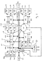
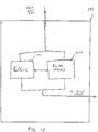
- FIG. 1 illustrates an exemplary configuration of a network switch wherein a switch-on-chip (SOC) 10 is functionally connected to external devices 11, external memory 12, fast Ethernet ports 13, and gigabit Ethernet ports 15.
- SOC switch-on-chip
- fast Ethernet ports 13 will be considered low speed Ethernet ports, since they are capable of operating at speeds ranging from 10 Mbps to 100 Mbps, while the gigabit Ethernet ports 15, which are high speed Ethernet ports, are capable of operating at 1000 Mbps.
- External devices 11 could include other switching devices for expanding switching capabilities, or other devices as may be required by a particular application.
- External memory 12 is additional off-chip memory, which is in addition to internal memory which is located on SOC 10, as will be discussed below.
- CPU 52 can be used as necessary to program SOC 10 with rules which are appropriate to control packet processing.
- SOC 10 operates, as much as possible, in a free running manner without communicating with CPU 52. Because CPU 52 does not control every aspect of the operation of SOC 10, CPU 52 performance requirements, at least with respect to SOC 10, are fairly low. A less powerful and therefore less expensive CPU 52 can therefore be used when compared to other network switches. As also will be discussed below, SOC 10 utilizes external memory 12 in an efficient manner so that the cost and performance requirements of memory 12 can be reduced. Internal memory on SOC 10, as will be discussed below, is also configured to maximize switching throughput and minimize costs. It should be noted that any number of fast Ethernet ports 13 and gigabit Ethernet ports 15 can be provided. In one exemplary configuration of the network switch, a maximum of 24 fast Ethernet ports 13 and 2 gigabit ports 15 can be provided. Similarly, additional interconnect links to additional external devices 11, external memory 12, and CPUs 52 may be provided as necessary.
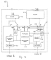
- FIG. 2 illustrates a more detailed block diagram of the functional elements of SOC 10.
- the exemplary SOC 10 includes a plurality of modular systems on-chip, with each modular system, although being on the same chip, being functionally separate from other modular systems. Therefore, each module can efficiently operate in parallel with other modules, and this configuration enables a significant amount of freedom in updating and re-engineering SOC 10.
- SOC 10 includes a plurality of Ethernet Port Interface Controllers (EPIC) 20a, 20b, 20c, etc., a plurality of Gigabit Port Interface Controllers (GPIC) 30a, 30b, etc., a CPU Management Interface Controller (CMIC) 40, a Common Buffer Memory Pool (CBP) 50, a Pipelined Memory Management Unit (PMMU) 70, including a Common Buffer Manager (CBM) 71, and a system-wide bus structure referred to as CPS channel 80.
- PMMU 70 communicates with external memory 12, which includes a Global Buffer Memory Pool (GBP) 60.
- the CPS channel 80 comprises C channel 81, P channel 82, and S channel 83.
- the CPS channel is also referred to as the Cell Protocol Sideband Channel, and is a 17 Gbps channel which glues or interconnects the various modules together.
- other high speed interconnects can be provided, as shown as an extendible high speed interconnect.
- This interconnect can be in the form of an interconnect port interface controller (IPIC) 90, which is capable of interfacing CPS channel 80 to external devices 11 through an extendible high speed interconnect link.
- IPIC interconnect port interface controller
- each EPIC 20a, 20b, and 20c are closely interrelated with appropriate address resolution logic and layer three switching tables 21 a, 21 b, 21 c, 31 a, 31 b, rules tables 22a, 22b, 22c, 31 a, 31 b, and VLAN tables 23a, 23b, 23c, 31 a, 31 b.
- These tables will be generally referred to as 21, 31, 22, 32, 23, 33, respectively.
- These tables like other tables on SOC 10, are implemented in silicon as two-dimensional arrays.
- EPIC 20 supports 8 fast Ethernet ports and switches packets to and/or from these ports as may be appropriate.
- the ports therefore, are connected to the network medium (coaxial, twisted pair, fiber, etc.) using known media connection technology, and communicates with the CPS channel 80 on the other side thereof.
- the interface of each EPIC 20 to the network medium can be provided through a Reduced Media Internal Interface (RMII), which enables the direct medium connection to SOC 10.
- RMII Reduced Media Internal Interface
- auto-negotiation is an aspect of fast Ethernet, wherein the network is capable of negotiating a highest communication speed between a source and a destination based on the capabilities of the respective devices.
- the communication speed can vary, as noted previously, between 10 Mbps and 100 Mbps; auto negotiation capability, therefore, is built directly into each EPIC module.
- the address resolution logic (ARL) and layer three tables (ARL/L3) 21a, 21 b, 21 c, rules table 22a, 22b, 22c, and VLAN tables 23a, 23b, and 23c are configured to be part of or interface with the associated EPIC in an efficient and expedient manner, also to support wirespeed packet flow.
- Each EPIC 20 has separate ingress and egress functions. On the ingress side, self-initiated and CPU-initiated learning of level 2 address information can occur. Address resolution logic is utilized to assist in this task. Address aging is built in as a feature, in order to eliminate the storage of address information which is no longer valid or useful.
- the EPIC also carries out layer 2 mirroring.
- a fast filtering processor (FFP) 141 (see Fig. 14 ) is incorporated into the EPIC, in order to accelerate packet forwarding and enhance packet flow.
- each EPIC and GPIC illustrated in Figure 8 as ingress submodule 14
- each port on each module of SOC 10 has a separate ingress submodule 14 associated therewith. From an implementation perspective, however, in order to minimize the amount of hardware implemented on the single-chip SOC 10, common hardware elements in the silicon can be used to implement a plurality of ingress submodules on each particular module.
- the configuration of SOC 10 discussed herein enables concurrent lookups and filtering, and therefore, processing of up to 6.6 million packets per second.
- the EPIC is capable of supporting packet polling based either as an egress management or class of service (COS) function. Rerouting/scheduling of packets to be transmitted can occur, as well as head-of-line (HOL) blocking notification, packet aging, cell reassembly, and other functions associated with Ethernet port interface.
- COS class of service
- Each GPIC 30 is similar to each EPIC 20, but supports only one gigabit Ethernet port, and utilizes a port-specific ARL table, rather than utilizing an ARL table which is shared with any other ports. Additionally, instead of an RMII, each GPIC port interfaces to the network medium utilizing a gigabit media independent interface (GMII).
- GMII gigabit media independent interface
- CMIC 40 acts as a gateway between the SOC 10 and the host CPU.
- the communication can be, for example, along a PCI bus, or other acceptable communications bus.
- CMIC 40 can provide sequential direct mapped accesses between the host CPU 52 and the SOC 10.
- CPU 52, through the CMIC 40, will be able to access numerous resources on SOC 10, including MIB counters, programmable registers, status and control registers, configuration registers, ARL tables, port-based VLAN tables, IEEE 802.1q VLAN tables, layer three tables, rules tables, CBP address and data memory, as well as GBP address and data memory.
- the CMIC 40 can include DMA support, DMA chaining and scatter-gather, as well as master and target PCI64.
- Common buffer memory pool or CBP 50 can be considered to be the on-chip data memory.
- the CBP 50 is first level high speed SRAM memory, to maximize performance and minimize hardware overhead requirements.
- the CBP can have a size of, for example, 720 kilobytes running at 132 MHz. Packets stored in the CBP 50 are typically stored as cells, rather than packets.
- PMMU 70 also contains the Common Buffer Manager (CBM) 71 thereupon.
- CBM 71 handles queue management, and is responsible for assigning cell pointers to incoming cells, as well as assigning common packet IDs (CPID) once the packet is fully written into the CBP.
- CBM 71 can also handle management of the on-chip free address pointer pool, control actual data transfers to and from the data pool, and provide memory budget management.
- Global memory buffer pool or GBP 60 acts as a second level memory, and can be located on-chip or off chip.
- GBP 60 is located off chip with respect to SOC 10.
- GBP 60 is considered to be a part of or all of external memory 12.
- the GBP does not need to be expensive high speed SRAMs, and can be a slower less expensive memory such as DRAM.
- the GBP is tightly coupled to the PMMU 70, and operates like the CBP in that packets are stored as cells. For broadcast and multicast messages, only one copy of the packet is stored in GBP 60.
- PMMU 70 is located between GBP 60 and CPS channel 80, and acts as an external memory interface.
- PMMU 70 includes multiple read and write buffers, and supports numerous functions including global queue management, which broadly includes assignment of cell pointers for rerouted incoming packets, maintenance of the global FAP, time-optimized cell management, global memory budget management, GPID assignment and egress manager notification, write buffer management, read prefetches based upon egress manager/class of service requests, and smart memory control.
- global queue management which broadly includes assignment of cell pointers for rerouted incoming packets, maintenance of the global FAP, time-optimized cell management, global memory budget management, GPID assignment and egress manager notification, write buffer management, read prefetches based upon egress manager/class of service requests, and smart memory control.
- the CPS channel 80 is actually three separate channels, referred to as the C-channel, the P-channel, and the S-channel.
- the C-channel is 128 bits wide, and runs at 132 MHz. Packet transfers between ports occur on the C-channel. Since this channel is used solely for data transfer, there is no overhead associated with its use.
- the P-channel or protocol channel is synchronous or locked with the C-channel. During cell transfers, the message header is sent via the P-channel by the PMMU.
- the P-channel is 32 bits wide, and runs at 132 MHz.
- the S or sideband channel runs at 132 MHz, and is 32 bits wide.
- the S-channel is used for functions such as four conveying Port Link Status, receive port full, port statistics, ARL table synchronization, memory and register access to CPU and other CPU management functions, and global memory full and common memory full notification.
- SOC 10 A proper understanding of the operation of an SOC 10 requires a proper understanding of the operation of CPS channel 80.
- packets are sliced by an EPIC 20 or GPIC 30 into 64-byte cells.
- the use of cells on-chip instead of packets makes it easier to adapt the SOC to work with cell based protocols such as, for example, Asynchronous Transfer Mode (ATM).
- ATM utilizes cells which are 53 bytes long, with 48 bytes for payload and 5 bytes for header.
- incoming packets are sliced into cells which are 64 bytes long as discussed above, and the cells are further divided into four separate 16 byte cell blocks Cn0...Cn3.
- Locked with the C-channel is the P-channel, which locks the opcode in synchronization with Cn0.
- a port bit map is inserted into the P-channel during the phase Cn1.
- the untagged bit map is inserted into the P-channel during phase Cn2, and a time stamp is placed on the P-channel in Cn3.
- the S-channel Independent from occurrences on the C and P-channel, the S-channel is used as a sideband, and is therefore decoupled from activities on the C and P-channel.
- C-channel arbitration is a demand priority round robin arbitration mechanism. If no requests are active, however, the default module, which can be selected during the configuration of SOC 10, can park on the channel and have complete access thereto. If all requests are active, the configuration of SOC 10 is such that the PMMU is granted access every other cell cycle, and EPICs 20 and GPICs 30 share equal access to the C-channel on a round robin basis.
- Figures 4A and 4B illustrate a C-channel arbitration mechanism wherein section A is the PMMU, and section B consists of two GPICs and three EPICs. The sections alternate access, and since the PMMU is the only module in section A, it gains access every other cycle. The modules in section B, as noted previously, obtain access on a round robin basis.
- a plurality of messages can be placed on the P-channel in order to properly direct flow of data flowing on the C-channel. Since P-channel 82 is 32 bits wide, and a message typically requires 128 bits, four smaller 32 bit messages are put together in order to form a complete P-channel message. The following list identifies the fields and function and the various bit counts of the 128 bit message on the P-channel.
- the opcode field of the P-channel message defines the type of message currently being sent. While the opcode is currently shown as having a width of 2 bits, the opcode field can be widened as desired to account for new types of messages as may be defined in the future. Graphically, however, the P-channel message type defined above is shown in Figure 5 .
- An early termination message is used to indicate to CBM 71 that the current packet is to be terminated.
- the status bit (S) field in the message is set to indicate the desire to purge the current packet from memory. Also in response to the status bit all applicable egress ports would purge the current packet prior to transmission.
- the Src Dest Port field of the P-channel message as stated above, define the destination and source port addresses, respectively. Each field is 6 bits wide and therefore allows for the addressing of sixty-four ports.
- the CRC field of the message is two bits wide and defines CRC actions. Bit 0 of the field provides an indication whether the associated egress port should append a CRC to the current packet. An egress port would append a CRC to the current packet when bit 0 of the CRC field is set to a logical one. Bit 1 of the CRC field provides an indication whether the associated egress port should regenerate a CRC for the current packet. An egress port would regenerate a CRC when bit 1 of the CRC field is set to a logical one.
- the CRC field is only valid for the last cell transmitted as defined by the E bit field of P-channel message set to a logical one.
- the status bit field (st), the Len field, and the Cell Count field of the message are only valid for the last cell of a packet being transmitted as defined by the E bit field of the message.
- the time stamp field of the message has a resolution of 1 ⁇ s and is valid only for the first cell of the packet defined by the S bit field of the message.
- a cell is defined as the first cell of a received packet when the S bit field of the message is set to a logical one value.
- the C channel 81 and the P channel 82 are synchronously tied together such that data on C channel 81 is transmitted over the CPS channel 80 while a corresponding P channel message is simultaneously transmitted.
- the S channel 83 is a 32-bit wide channel which provides a separate communication path within the SOC 10.
- the S channel 83 is used for management by CPU 52, SOC 10 internal flow control, and SOC 10 inter-module messaging.
- the S channel 83 is a sideband channel of the CPS channel 80, and is electrically and physically isolated from the C channel 81 and the P channel 82. It is important to note that since the S channel is separate and distinct from the C channel 81 and the P channel 82, operation of the S channel 83 can continue without performance degradation related to the C channel 81 and P channel 82 operation. Conversely, since the C channel is not used for the transmission of system messages, but rather only data, there is no overhead associated with the C channel 81 and, thus, the C channel 81 is able to free-run as needed to handle incoming and outgoing packet information.
- the S channel 83 of CPS channel 80 provides a system wide communication path for transmitting system messages, for example, providing the CPU 52 with access to the control structure of the SOC 10.
- System messages include port status information, including port link status, receive port full, and port statistics, ARL table 22 synchronization, CPU 52 access to GBP 60 and CBP 50 memory buffers and SOC 10 control registers, and memory full notification corresponding to GBP 60 and/or CBP 50.
- Figure 6 illustrates a message format for an S channel message on S channel 83.
- the message is formed of four 32-bit words; the bits of the fields of the words are defined as follows:
- the decoupling of the S channel from the C channel and the P channel is such that the bandwidth on the C channel can be preserved for cell transfer, and that overloading of the C channel does not affect communications on the sideband channel.
- the configuration of the exemplary SOC 10 supports fast Ethernet ports, gigabit ports, and extendible interconnect links as discussed above.
- the SOC configuration can also be "stacked", thereby enabling significant port expansion capability.
- a significant amount of concurrent lookups and filtering occurs as the packet comes in to ingress submodule 14 of an EPIC 20 or GPIC 30, with respect to layer two and layer three lookups, and fast filtering.
- Ethernet data to be received will consider to arrive at one of the ports 24a of EPIC 20a. It will be presumed that the packet is intended to be transmitted to a user on one of ports 24c of EPIC 20c. All EPICs 20 (20a, 20b, 20c, etc.) have similar features and functions, and each individually operate based on packet flow.
- the data packet 112 is applied to the port 24a is shown.
- the data packet 112 is, in this example, defined per the current standards for 10/100 Mbps Ethernet transmission and may have any length or structure as defined by that standard. This discussion will assume the length of the data packet 112 to be 1024 bits or 128 bytes.
- an ingress sub-module 14a determines the destination of the packet 112.
- the first 64 bytes of the data packet 112 is buffered by the ingress sub-module 14a and compared to data stored in the lookup tables 21 a to determine the destination port 24c.
- the ingress sub-module 14a slices the data packet 112 into a number of 64-byte cells; in this case, the 128 byte packet is sliced in two 64 byte cells 112a and 112b.
- an actual incoming data packet may include any number of cells, with' at least one cell of a length less than 64 bytes. Padding bytes are used to fill the cell. In such cases the ingress sub-module 14a disregards the padding bytes within the cell. Further discussions of packet handling will refer to packet 112 and/or cells 112a and 112b.
- each EPIC 20 (as well as each GPIC 30) has an ingress submodule 14 and egress submodule 16, which provide port specific ingress and egress functions. All incoming packet processing occurs in ingress submodule 14, and features such as the fast filtering processor, layer two (L2) and layer three (L3) lookups, layer two learning, both self-initiated and CPU 52 initiated, layer two table management, layer two switching, packet slicing, and channel dispatching occurs in ingress submodule 14. After lookups, fast filter processing, and slicing into cells, as noted above and as will be discussed below, the packet is placed from ingress submodule 14 into dispatch unit 18, and then placed onto CPS channel 80 and memory management is handled by PMMU 70.
- L2 layer two
- L3 layer three
- a number of ingress buffers are provided in dispatch unit 18 to ensure proper handling of the packets/cells. Once the cells or cellularized packets are placed onto the CPS channel 80, the ingress submodule is finished with the packet. The ingress is not involved with dynamic memory allocation, or the specific path the cells will take toward the destination.
- PMMU 70 When the PMMU 70 receives a signal that an egress associated with a destination of a packet in memory is ready to receive cells, PMMU 70 pulls the cells associated with the packet out of the memory, as will be discussed below, and places the cells on CPS channel 80, destined for the appropriate egress submodule.
- a FIFO in the egress submodule 16 continuously sends a signal onto the CPS channel 80 that it is ready to receive packets, when there is room in the FIFO for packets or cells to be received.
- the CPS channel 80 is configured to handle cells, but cells of a particular packet are always handled together to avoid corrupting of packets.
- L2 self-initiated learning is achieved by deciphering the source address of a user at a given ingress port 24 utilizing the packet's associated address. Once the identity of the user at the ingress port 24 is determined, the ARUL3 tables 21 a are updated to reflect the user identification. The ARUL3 tables 21 of each other EPIC 20 and GPIC 30 are updated to reflect the newly acquired user identification in a synchronizing step, as will be discussed below.
- the ingress of EPIC 20a may determine that a given user is at a given port 24a
- the egress of EPIC 20b whose table 21 b has been updated with the user's identification at port 24a, can then provide information to the User at port 24a without re-learning which port the user was connected.
- Table management may also be achieved through the use of the CPU 52.
- CPU 52 via the CMIC 40, can provide the SOC 10 with software functions which result in the designation of the identification of a user at a given port 24. As discussed above, it is undesirable for the CPU 52 to access the packet information in its entirety since this would lead to performance degradation. Rather, the SOC 10 is programmed by the CPU 52 with identification information concerning the user. The SOC 10 can maintain real-time data flow since the table data communication between the CPU 52 and the SOC 10 occurs exclusively on the S channel 83. While the SOC 10 can provide the CPU 52 with direct packet information via the C channel 81, such a system setup is undesirable for the reasons set forth above.
- an address resolution lookup is performed by examining the ARL table 21a. If the packet is addressed to one of the layer three (L3) switches of the SOC 10, then the ingress sub-module 14a performs the L3 and default table lookup. Once the destination port has been determined, the EPIC 20a sets a ready flag in the dispatch unit 18a which then arbitrates for C channel 81.
- L3 layer three
- the C channel 81 arbitration scheme is Demand Priority Round-Robin.
- EPIC modules 20a, 20b, 20c, and GPIC modules 30a and 30b, and CMIC 40 simultaneously request C channel access, then access is granted in round-robin fashion. For a given arbitration time period each of the I/O modules would be provided access to the C channel 81. For example, each GPIC module 30a and 30b would be granted access, followed by the EPIC modules, and finally the CMIC 40. After every arbitration time period the next I/O module with a valid request would be given access to the C channel 81. This pattern would continue as long as each of the I/O modules provide an active C channel 81 access request.
- the PMMU 70 is granted access as shown in Fig. 4B since the PMMU provides a critical data path for all modules on the switch.
- the dispatch unit 18a Upon gaining access to the channel 81, the dispatch unit 18a proceeds in passing the received packet 112, one cell at a time, to C channel 81.
- the dispatch unit 18a places the first 16 bytes of the first cell 112a of the received packet 112 on the C channel 81. Concurrently, the dispatch unit 18a places the first P channel message corresponding to the currently transmitted cell.
- the first P channel message defines, among other things, the message type. Therefore, this example is such that the first P channel message would define the current cell as being a unicast type message to be directed to the destination egress port 21c.
- the second 16 bytes (16:31) of the currently transmitted data cell 112a are placed on the C channel 81.
- the B/cMc Port Bitmap is placed on the P channel 82.
- the operation of the S channel 83 is decoupled from the operation of the C channel 81 and the P channel 82.
- the CPU 52 via the CMIC 40, can pass system level messages to non-active modules while an active module passes cells on the C channel 81.
- this is an important aspect of the SOC 10 since the S channel operation allows parallel task processing, permitting the transmission of cell data on the C channel 81 in real-time.
- PMMU 70 includes CBM 71, and interfaces between the GBP, CBP and a plurality of egress managers (EgM) 76 of egress submodule 18, with one egress manager 76 being provided for each egress port.
- CBM 71 is connected to each egress manager 76, in a parallel configuration, via R channel data bus 77.
- R channel data bus 77 is a 32-bit wide bus used by CBM 71 and egress managers 76 in the transmission of memory pointers and system messages.
- Each egress manager 76 is also connected to CPS channel 80, for the transfer of data cells 112a and 112b.
- CBM 71 performs the functions of on-chip FAP (free address pool) management, transfer of cells to CBP 50, packet assembly and notification to the respective egress managers, rerouting of packets to GBP 60 via a global buffer manager, as well as handling packet flow from the GBP 60 to CBP 50.
- Memory clean up, memory budget management, channel interface, and cell pointer assignment are also functions of CBM 71.
- CBM 71 manages the free address pool and assigns free cell pointers to incoming cells. The free address pool is also written back by CBM 71, such that the released cell pointers from various egress managers 76 are appropriately cleared.
- CBM 71 maintains at least two cell pointers per egress manager 76 which is being managed.
- the first cell of a packet arrives at an egress manager 76, and CBM 71 writes this cell to the CBM memory allocation at the address pointed to by the first pointer.
- the second pointer is written.
- the format of the cell as stored in CBP 50 is shown in Figure 11 ; each line is 18 bytes wide. Line 0 contains appropriate information with respect to first cell and last cell information, broadcast/multicast, number of egress ports for broadcast or multicast, cell length regarding the number of valid bytes in the cell, the next cell pointer, total cell count in the packet, and time stamp.
- the remaining lines contain cell data as 64 byte cells.
- the free address pool within PMMU 70 stores all free pointers for CBP 50. Each pointer in the free address pool points to a 64-byte cell in CBP 50; the actual cell stored in the CBP is a total of 72 bytes, with 64 bytes being byte data, and 8 bytes of control information.
- Functions such as HOL blocking high and low watermarks, out queue budget registers, CPID assignment, and other functions are handled in CBM 71, as explained herein.
- PMMU 70 determines that cell 112a is destined for an appropriate egress port on SOC 10.
- PMMU 70 controls the cell flow from CPS channel 80 to CBP 50.
- CBM 71 determines whether or not sufficient memory is available in CBP 50 for the data packet 112.
- a free address pool (not shown) can provide storage for at least two cell pointers per egress manager 76, per class of service. If sufficient memory is available in CBP 50 for storage and identification of the incoming data packet, CBM 71 places the data cell information on CPS channel 80. The data cell information is provided by CBM 71 to CBP 50 at the assigned address. As new cells are received by PMMU 70, CBM 71 assigns cell pointers.
- the initial pointer for the first cell 112a points to the egress manager 76 which corresponds to the egress port to which the data packet 112 will be sent after it is placed in memory.
- packets come in to port 24a of EPIC 20a, and are destined for port 24c of EPIC 20c.
- CBM 71 assigns a corresponding pointer.
- This corresponding cell pointer is stored as a two byte or 16 bit value NC_header, in an appropriate place on a control message, with the initial pointer to the corresponding egress manager 76, and successive cell pointers as part of each cell header, a linked list of memory pointers is formed which defines packet 112 when the packet is transmitted via the appropriate egress port, in this' case 24c.
- a corresponding CBP Packet Identifier CPID
- the CPID for the data packet is then used when the data packet 112 is sent to the destination egress port 24c.
- the CBM 71 maintains two buffers containing a CBP cell pointer, with admission to the CBP being based upon a number of factors. An example of admission logic for CBP 50 will be discussed below with reference to Figure 12 .
- CBM 71 Since CBM 71 controls data flow within SOC 10, the data flow associated with any ingress port can likewise be controlled.
- a CPID is provided to the associated egress manager 76.
- the total number of data cells associated with the data packet is stored in a budget register (not shown).
- the value of the budget register corresponding to the associated egress manager 76 is incremented by the number of data cells 112a, 112b of the new data cells received.
- the budget register therefore dynamically represents the total number of cells designated to be sent by any specific egress port on an EPIC 20.
- CBM 71 controls the inflow of additional data packets by comparing the budget register to a high watermark register value or a low watermark register value, for the same egress.
- the associated ingress port When the value of the budget register exceeds the high watermark value, the associated ingress port is disabled. Similarly, when data cells of an egress manager 76 are sent via the egress port, and the corresponding budget register decreases to a value below the low watermark value, the ingress port is once again enabled. When egress manager 76 initiates the transmission of packet 112, egress manager 76 notifies CBM 71, which then decrements the budget register value by the number of data cells which are transmitted.
- the specific high watermark values and low watermark values can be programmed by the user via CPU 52. This gives the user control over the data flow of any port on any EPIC 20 or GPIC 30.
- Egress manager 76 is also capable of controlling data flow. Each egress manager 76 is provided with the capability to keep track of packet identification information in a packet pointer budget register; as a new pointer is received by egress manager 76, the associated packet pointer budget register is incremented. As egress manager 76 sends out a data packet 112, the packet pointer budget register is decremented. When a storage limit assigned to the register is reached, corresponding to a full packet identification pool, a notification message is sent to all ingress ports of the SOC 10, indicating that the destination egress port controlled by that egress manager 76 is unavailable. When the packet pointer budget register is decremented below the packet pool high watermark value, a notification message is sent that the destination egress port is now available. The notification messages are sent by CBM 71 on the S channel 83.
- flow control may be provided by CBM 71, and also by ingress submodule 14 of either an EPIC 20 or GPIC 30.
- Ingress submodule 14 monitors cell transmission into ingress port 24. When a data packet 112 is received at an ingress port 24, the ingress submodule 14 increments a received budget register by the cell count of the incoming data packet. When a data packet 112 is sent, the corresponding ingress 14 decrements the received budget register by the cell count of the outgoing data packet 112.
- the budget register 72 is decremented by ingress 14 in response to a decrement cell count message initiated by CBM 71, when a data packet 112 is successfully transmitted from CBP 50.
- Figure 12 generally illustrates the handling of a data packet 112 when it is received at an appropriate ingress port. This figure illustrates dynamic memory allocation on a single port, and is applicable for each ingress port.
- packet length is estimated by estimating cell count based upon egress manager count plus incoming cell count.
- the GBP current cell count is checked at step 12-2 to determine whether or not the GBP 60 is empty. If the GBP cell count is 0, indicating that GBP 60 is empty, the method proceeds to step 12-3, where it is determined whether or not the estimated cell count from step 12-1 is less than the admission low watermark.
- the admission low watermark value enables the reception of new packets 112 into CBP 50 if the total number of cells in the associated egress is below the admission low watermark value. If yes, therefore, the packet is admitted at step 12-5. If the estimated cell count is not below the admission low watermark, CBM 71 then arbitrates for CBP memory allocation with other ingress ports of other EPICs and GPICs, in step 12-4. If the arbitration is unsuccessful, the incoming packet is sent to a reroute process, referred to as A. If the arbitration is successful, then the packet is admitted to the CBP at step 12-5. Admission to the CBP is necessary for linespeed communication to occur.
- step 12-2 the GBP cell count is determined not to be 0, then the method proceeds to step 12-6, where the estimated cell count determined in step 12-1 is compared to the admission high watermark. If the answer is no, the packet is rerouted to GBP 60 at step 12-7. If the answer is yes, the estimated cell count is then compared to the admission low watermark at step 12-8. If the answer is no, which means that the estimated cell count is between the high watermark and the low watermark, then the packet is rerouted to GBP 60 at step 12-7. If the estimated cell count is below the admission low watermark, the GBP current count is compared with a reroute cell limit value at step 12-9.
- This reroute cell limit value is user programmable through CPU 52. If the GBP count is below or equal to the reroute cell limit value at step 12-9, the estimated cell count and GBP count are compared with an estimated cell count low watermark; if the combination of estimated cell count and GBP count are less than the estimated cell count low watermark, the packet is admitted to the CBP. If the sum is greater than the estimated cell count low watermark, then the packet is rerouted to GBP 60 at step 12-7. After rerouting to GBP 60, the GBP cell count is updated, and the packet processing is finished. It should be noted that if both the CBP and the GBP are full, the packet is dropped.
- Dropped packets are handled in accordance with known Ethernet or network communication procedures, and have the effect of delaying communication.
- this configuration applies appropriate back pressure by setting watermarks, through CPU 52, to appropriate buffer values on a per port basis to maximize memory utilization.
- This CBP/GBP admission logic results in a distributed hierarchical shared memory configuration, with a hierarchy between CBP 50 and GBP 60, and hierarchies within the CBP.
- Figure 14 illustrates some of the concurrent filtering and look-up details of a packet coming into the ingress side of an EPIC 20.
- Figure 12 illustrates the handling of a data packet with respect to admission into the distributed hierarchical shared memory.
- Figure 14 addresses the application of filtering, address resolution, and rules application segments of SOC 10. These functions are performed simultaneously with respect to the CBP admission discussed above.
- packet 112 is received at input port 24 of EPIC 20. It is then directed to input FIFO 142. As soon as the first sixteen bytes of the packet arrive in the input FIFO 142, an address resolution request is sent to ARL engine 143; this initiates lookup in ARUL3 tables 21.
- a description of the fields of an ARL table of ARL/L3 tables 21 is as follows:
- VLAN tables 23 include a number of table formats; all of the tables and table formats will not be discussed here. However, as an example, the port based VLAN table fields are described as follows:
- the ARL engine 143 reads the packet; if the packet has a VLAN tag according to IEEE Standard 802.1 q, then ARL engine 143 performs a look-up based upon tagged VLAN table 231, which is part of VLAN table 23. If the packet does not contain this tag, then the ARL engine performs VLAN lookup based upon the port based VLAN table 232. Once the VLAN is identified for the incoming packet, ARL engine 143 performs an ARL table search based upon the source MAC address and the destination MAC address. If the results of the destination search is an L3 interface MAC address, then an L3 search is performed of an L3 table within ARUL3 table 21. If the L3 search is successful, then the packet is modified according to packet routing rules.
- ingress submodule 14a slices data packet 112 into cells 112a and 112b. The ingress submodule then reads the packet to determine the source MAC address and the destination MAC address.
- ingress submodule 14a performs the lookup of appropriate tables within ARUL3 tables 21a, and VLAN table 23a, to see if the destination MAC address exists in ARUL3 tables 21a; if the address is not found, but if the VLAN IDs are the same for the source and destination, then ingress submodule 14a will set the packet to be sent to all ports. The packet will then propagate to the appropriate destination address. A "source search” and a "destination search” occurs in parallel. Concurrently, the source MAC address of the incoming packet is "learned", and therefore added to an ARL table within ARUL3 table 21a. After the packet is received by the destination, an acknowledgement is sent by destination station B to source station A.
- the acknowledgement is appropriately sent to the port on which A is located.
- the ARL table learns the source MAC address of B from the acknowledgement packet. It should be noted that as long as the VLAN IDs (for tagged packets) of source MAC addresses and destination MAC addresses are the same, layer two switching as discussed above is performed. L2 switching and lookup is therefore based on the first 16 bytes of an incoming packet. For untagged packets, the port number field in the packet is indexed to the port-based VLAN table within VLAN table 23a, and the VLAN ID can then be determined.
- L3 switching is necessary wherein the packets are sent to a different VLAN.
- L3 switching is based on the IP header field of the packet.
- the IP header includes source IP address, destination IP address, and TTL (time-to-live).
- data packet 112 is sent from source station A onto port 24a of EPIC 20a, and is directed to destination station B; assume, however, that station B is disposed on a different VLAN, as evidenced by the source MAC address and the destination MAC address having differing VLAN IDs.
- the lookup for B would be unsuccessful since B is located on a different VLAN, and merely sending the packet to all ports on the VLAN would result in B never receiving the packet.
- Layer three switching therefore, enables the bridging of VLAN boundaries, but requires reading of more packet information than just the MAC addresses of L2 switching.
- ingress 14a also reads the IP address of the source and destination.
- Packet 112 is therefore sent on to CPS channel 80 through dispatch unit 18a, destined for an appropriate router interface (not shown, and not part of SOC 10), upon which destination B is located.
- Control frames identified as such by their destination address, are sent to CPU 52 via CMIC 40.
- the destination MAC address therefore, is the router MAC address for B.
- the router MAC address is learned through the assistance of CPU 52, which uses an ARP (address resolution protocol) request to request the destination MAC address for the router for B, based upon the IP address of B.
- ARP address resolution protocol
- SOC 10 can learn the MAC address. Through the acknowledgement and learning process, however, it is only the first packet that is subject to this "slow" handling because of the involvement of CPU 52. After the appropriate MAC addresses are learned, linespeed switching can occur through the use of concurrent table lookups since the necessary information will be learned by the tables. Implementing the tables in silicon as two-dimensional arrays enables such rapid concurrent lookups. Once the MAC address for B has been learned, therefore, when packets come in with the IP address for B, ingress 14a changes the IP address to the destination MAC address, in order to enable linespeed switching.
- the source address of the incoming packet is changed to the router MAC address for A rather than the IP address for A, so that the acknowledgement from B to A can be handled in a fast manner without needing to utilize a CPU on the destination end in order to identify the source MAC address to be the destination for the acknowledgement.
- a TTL (time-to-live) field in the packet is appropriately manipulated in accordance with the IETF (Internet Engineering Task Force) standard.
- IETF Internet Engineering Task Force
- a unique aspect of SOC 10 is that all of the switching, packet processing, and table lookups are performed in hardware, rather than requiring CPU 52 or another CPU to spend time processing instructions.
- the layer three tables for EPIC 20 can have varying sizes; in the exemplary switch configuration, these tables are capable of holding up to 2000 addresses, and are subject to purging and deletion of aged addresses, as explained herein.
- FFP 141 is an extensive filtering mechanism which enables SOC 10 to set inclusive and exclusive filters on any field of a packet from layer 2 to layer 7 of the OSI seven layer model. Filters are used for packet classification based upon protocol fields in the packets, and with respect to VOIP configurations discussed below, the filters are uses to trap and prioritize VOIP packets in order to reduce latency.
- the exclusive filter is primarily used for implementing security features, and allows a packet to proceed only if there is a filter match. If there is no match, the packet is discarded.
- the exemplary SOC 10 has a unique capability to handle both tagged and untagged packets coming in.
- Tagged packets are tagged in accordance with IEEE standards, and include a specific IEEE 802.1p priority field for the packet. Untagged packets, however, do not include an 802.1 p priority field therein.
- SOC 10 can assign an appropriate COS value for the packet, which can be considered to be equivalent to a weighted' priority, based either upon the destination address or the source address of the packet, as matched in one of the table lookups.
- an SCP Source COS Priority
- SOC 10 When this SCP bit is set, then SOC 10 will assign weighted priority based upon a source COS value in the ARL table. If the SCP is not set, then SOC 10 will assign a COS for the packet based upon the destination COS field in the ARL table.
- These COS of values are three bit fields in the ARL table, as noted previously in the ARL table field descriptions.
- FFP 141 is essentially a state machine driven programmable rules engine.
- the filters used by the FFP are 64 (sixty-four) bytes wide, and are applied on an incoming packet; any offset can be used, however, the exemplary switch configuration uses an offset of zero, and therefore operates on the first 64 bytes, or 512 bits, of a packet.
- the actions taken by the filter are tag insertion, priority mapping, TOS tag insertion, sending of the packet to the CPU, dropping of the packet, forwarding of the packet to an egress port, and sending the packet to a mirrored port.
- the filters utilized by FFP 141 are defined by rules table 22. Rules table 22 is completely programmable by CPU 52, through CMIC 40.
- the rules table can be, for example, 256 entries deep, and may be partitioned for inclusive and exclusive filters, with, again as an example, 128 entries for inclusive filters and 128 entries for exclusive filters.
- a filter database within FFP 141, includes a number of inclusive mask registers and exclusive mask registers, such that the filters are formed based upon the rules in rules table 22, and the filters therefore essentially form a 64 byte wide mask or bit map which is applied on the incoming packet. If the filter is designated as an exclusive filter, the filter will exclude all packets unless there is a match. In other words, the exclusive filter allows a packet to go through the forwarding process only if there is a filter match. If there is no filter match, the packet is dropped.
- an inclusive filter if there is no match, no action is taken but the packet is not dropped.
- Action on an exclusive filter requires an exact match of all filter fields. If there is an exact match with an exclusive filter, therefore, action is taken as specified in the action field; the actions which may be taken, are discussed above. If there is no full match or exact of all of the filter fields, but there is a partial match, then the packet is dropped.
- a partial match is defined as either a match on the ingress field, egress field, or filter select fields. If there is neither a full match nor a partial match with the packet and the exclusive filter, then no action is taken and the packet proceeds through the forwarding process.
- the FFP configuration taking action based upon the first 64 bytes of a packet, enhances the handling of real time traffic since packets can be filtered and action can be taken on the fly. Without an FFP according to the invention, the packet would need to be transferred to the CPU for appropriate action to be interpreted and taken. For inclusive filters, if there is a filter match, action is taken, and if there is no filter match, no action is taken; however, packets are not dropped based on a match or no match situation for inclusive filters.
- the FFP includes a filter database with eight sets of inclusive filters and eight sets of exclusive filters, as separate filter masks.
- the filter masks are applied to the packet; in other words, a logical AND operation is performed with the mask and the packet. If there is a match, the matching entries are applied to rules tables 22, in order to determine which specific actions will be taken.
- the actions include 802.1 p tag insertion, 802.1 p priority mapping, IP TOS (type-of-service) tag insertion, sending of the packet to the CPU, discarding or dropping of the packet, forwarding the packet to an egress port, and sending the packet to the mirrored port.
- the rules table requirements are minimized in the present exemplary network switch by the switch setting all incoming packets to be "tagged" packets; all untagged packets, therefore, are subject to 802.1 p tag insertion, in order to reduce the number of entries which are necessary in the rules table. This action eliminates the need for entries regarding handling of untagged packets. It should be noted that specific packet types are defined by various IEEE and other networking standards, and will not be defined herein.
- FFP 141 is shown to include filter database 1410 containing filter masks therein, communicating with logic circuitry 1411 for determining packet types and applying appropriate filter masks. After the filter mask is applied as noted above, the result of the application is applied to rules table 22, for appropriate lookup and action. It should be noted that the filter masks, rules tables, and logic, while programmable by CPU 52, do not rely upon CPU 52 for the processing and calculation thereof. After programming, a hardware configuration is provided which enables linespeed filter application and lookup.
- FFP 141 determines and takes the appropriate action.
- the filtering logic can discard the packet, send the packet to the CPU 52, modify the packet header or IP header, and recalculate any IP checksum fields or takes other appropriate action with respect to the headers.
- the modification occurs at buffer slicer 144, and the packet is placed on C channel 81.
- the control message and message header information is applied by the FFP 141 and ARL engine 143, and the message header is placed on P channel 82.
- Dispatch unit 18, also generally discussed with respect to Figure 8 coordinates all dispatches to C channel, P channel and S channel.
- each EPIC module 20, GPIC module 30, PMMU 70, etc. are individually configured to communicate via the CPS channel.
- Each module can be independently modified, and as long as the CPS channel interfaces are maintained, internal modifications to any modules such as EPIC 20a should not affect any other modules such as EPIC 20b, or any GPICs 30.
- FFP 141 is programmed by the user, through CPU 52, based upon the specific functions which are sought to be handled by each FFP 141.
- an FFP programming step is initiated by the user, or alternatively, this step can be initiated by preprogrammed software without direct user involvement.
- the user identifies the protocol fields of the packet which are to be of interest for the filter, in step 17-2.
- the packet type and filter conditions are determined, and in step 17-4, a filter mask is constructed based upon the identified packet type, and the desired filter conditions.
- the filter mask is essentially a bit map which is applied or ANDed with selected fields of the packet.
- step 17-6 it is determined whether or not the filter is on the ingress port, and in step 17-7, it is determined whether or not the filter is on the egress port. If the filter is on the ingress port, an ingress port mask is used in step 17-8. If it is determined that the filter will be on the egress port, then an egress mask is used in step 17-9. Based upon these steps, a rules table entry for rules tables 22 is then constructed, and the entry or entries are placed into the appropriate rules table (steps 17-10 and 17-11).
- FIG. 2 the block diagram of SOC 10 in Figure 2 illustrates each GPIC 30 having its own ARL/L3 tables 31, rules table 32, and VLAN tables 33, and also each EPIC 20 also having its own ARUL3 tables 21, rules table 22, and VLAN tables 23.
- two separate modules can share a common ARUL3 table and a common VLAN table.
- Each module has its own rules table 22.
- GPIC 30a may share ARL/L3 table 21a and VLAN table 23a with EPIC 20a.
- GPIC 30b may share ARL table 21 b and VLAN table 23b with EPIC 20b. This sharing of tables reduces the number of gates which are required to implement the invention, and makes for simplified lookup and synchronization as will be discussed below.
- SOC 10 utilizes a unique method of table synchronization and aging, to ensure that only current and active address information is maintained in the tables.
- ARUL3 tables are updated to include a new source address
- a "hit bit" is set within the table of the "owner” or obtaining module to indicate that the address has been accessed.
- an S channel message is placed on S channel 83 as an ARL insert message, instructing all ARUL3 tables on SOC 10 to learn this new address.
- the entry in the ARUL3 tables includes an identification of the port which initially received the packet and learned the address. Therefore, if EPIC 20a contains the port which initially received the packet and therefore which initially learned the address, EPIC 20a becomes the "owner" of the address.
- An age timer is provided within each EPIC module 20 and GPIC module 30, at step 18-1, it is determined whether the age timer has expired. If the timer has expired, the aging process begins by examining the first entry in ARL table 21. At step 18-2, it is determined whether or not the port referred to in the ARL entry belongs to the particular module. If the answer is no, the process proceeds to step 18-3, where it is determined whether or not this entry is the last entry in the table. If the answer is yes at step 18-3, the age timer is restarted and the process is completed at step 18-4. If this is not the last entry in the table, then the process is returned to the next ARL entry at step 18-5.
- step 18-6 it is determined whether or not the hit bit is set, or if this is a static entry. If the hit bit is set, the hit bit is reset at step 18-7, and the method then proceeds to step 18-3. If the hit bit is not set, the ARL entry is deleted at step 18-8, and a delete ARL entry message is sent on the CPS channel to the other modules, including CMIC 40, so that the table can be appropriately synchronized as noted above.
- This aging process can be performed on the ARL (layer two) entries, as well as layer three entries, in order to ensure that aged packets are appropriately deleted from the tables by the owners of the entries.
- the aging process is only performed on entries where the port referred to belongs to the particular module which is performing the aging process. To this end, therefore, the hit bit is only set in the owner module. The hit bit is not set for entries in tables of other modules which receive the ARL insert message. The hit bit is therefore always set to zero in the synchronized non-owner tables.
- the purpose of the source and destination searches, and the overall lookups, is to identify the port number within SOC 10 to which the packet should be directed to after it is placed either CBP 50 or GBP 60.
- a source lookup failure results in learning of the source from the source MAC address information in the packet;
- a destination lookup failure results in the packet being sent to all ports on SOC 10.
- the packet will propagate the VLAN and reach the ultimate destination, at which point an acknowledgement packet will be received, thereby enabling the ARL table to learn the destination port for use on subsequent packets. If the VLAN IDs are different, an L3 lookup and learning process will be performed, as discussed previously.
- each EPIC and each GPIC contains a FIFO queue to store ARL insert messages, since, although each module can only send one message at a time, if each module sends an insert message, a queue must be provided for appropriate handling of the messages.
- SOC 10 includes capabilities of identifying such movement, and updating the table entries appropriately. For example, if station A, located for example on port 1, seeks to communicate with station B, whose entries indicate that user B is located on port 26. If station B is then moved to a different port, for example, port 15, a destination lookup failure will occur and the packet will be sent to all ports. When the packet is received by station B at port 15, station B will send an acknowledge (ACK) message, which will be received by the ingress of the EPIC/GPIC module containing port 1 thereupon.
- ACK acknowledge
- a source lookup (of the acknowledge message) will yield a match on the source address, but the port information will not match.
- the EPIC/GPIC which receives the packet from B, therefore, must delete the old entry from the ARUL3 table, and also send an ARUL3 delete message onto the S channel so that all tables are synchronized. Then, the new source information, with the correct port, is inserted into the ARUL3 table, and an ARUL3 insert message is placed on the S channel, thereby synchronizing the ARL/L3 tables with the new information.
- the updated ARL insert message cannot be sent until all of the acknowledgement messages are sent regarding the ARL delete message, to ensure proper table synchronization.
- typical ARL insertion and deletion commands can only be initiated by the owner module. In the case of port movement, however, since port movement may be identified by any module sending a packet to a moved port, the port movement-related deletion and insertion messages can be initiated by any module.
- a local area network is configured by an administrator with a plurality of switches, etc.
- numerous ports can be "trunked" to increase bandwidth.
- the LAN can be configured such that a plurality of ports, for example ports 1 and 2, can be connected together.
- the trunking of two ports effectively provides an increased bandwidth of 200 megabits per second between the two ports.
- the two ports 1 and 2 are therefore identified as a trunk group, and CPU 52 is used to properly configure the handling of the trunk group. Once a trunk group is identified, it is treated as a plurality of ports acting as one logical port.
- Figure 19 illustrates a configuration wherein SW1, containing a plurality of ports thereon, has a trunk group with ports 1 and 2 of SW2, with the trunk group being two communication lines connecting ports 1 and 2 of each of SW1 and SW2.
- station A connected to port 3 of SW1, is seeking to communicate or send a packet to station B, located on port 26 of switch SW2.
- the packet must travel, therefore, through trunk group T from port 3 of SW1 to port 26 of SW2.
- the trunk group could include any of a number of ports between the switches.
- trunk group T could be reconfigured by the administrator to include more ports, thereby effectively increasing bandwidth.
- trunking provides redundancy in the event of a failure of one of the links between the switches.
- a user programs SOC 10 through CPU 52 to recognize the appropriate trunk group or trunk groups, with trunk group identification (TGID) information.
- a trunk group port bit map is prepared for each TGID; and a trunk group table, provided for each module on SOC 10, is used to implement the trunk group, which can also be called a port bundle.
- a trunk group bit map table is also provided. These two tables are provided on a per module basis, and, like tables 21, 22, and 23, are implemented in silicon as two-dimensional arrays. In one configuration of SOC 10, six trunk groups can be supported, with each trunk group having up to eight trunk ports thereupon.
- the same port In order to prevent out-of-ordering of packets or frames, the same port must be used for packet flow. Identification of which port will be used for communication is based upon any of the following: source MAC address, destination MAC address, source IP address, destination IP address, or combinations of source and destination addresses. If source MAC is used, as an example, if station A on port 3 of SW1 is seeking to send a packet to station B on port 26 of SW2, then the last three bits of the source MAC address of station A, which are in the source address field of the packet, are used to generate a trunk port index.
- the trunk port index which is then looked up on the trunk group table by the ingress submodule 14 of the particular port on the switch, in order to determine which port of the trunk group will be used for the communication.
- address resolution is conducted as set forth above. If the packet is to be handled through a trunk group, then a T bit will be set in the ARL entry which is matched by the destination address. If the T bit or trunk bit is set, then the destination address is learned from one of the trunk ports.
- the egress port therefore, is not learned from the port number obtained in the ARL entry, but is instead learned from the trunk group ID and rules tag (RTAG) which is picked up from the ARL entry, and which can be used to identify the trunk port based upon the trunk port index contained in the trunk group table.
- the RTAG and TGID which are contained in the ARL entry therefore define which part of the packet is used to generate the trunk port index. For example, if the RTAG value is 1, then the last three bits of the source MAC address are used to identify the trunk port index; using the trunk group table, the trunk port index can then be used to identify the appropriate trunk port for communication. If the RTAG value is 2, then it is the last three bits of the destination MAC address which are used to generate the trunk port index.
- RTAG 3
- SOC 10 is configured such that if a trunk port goes down or fails for any reason, notification is sent through CMIC 40 to CPU 52.
- CPU 52 is then configured to automatically review the trunk group table, and VLAN tables to make sure that the appropriate port bit maps are changed to reflect the fact that a port has gone down and is therefore removed.
- the process has to be reversed and a message must be sent to CPU 52 so that the VLAN tables, trunk group tables, etc. can be updated to reflect the presence of the trunk port.
- the trunk group is configured to accept control frames or control packets, also known as BPDUs, only one of the trunk ports.
- the port based VLAN table therefore, must be configured to reject incoming BPDUs of non-specified trunk ports. This rejection can be easily set by the setting of a B bit in the VLAN table.
- IEEE standard 802.1d defines an algorithm known as the spanning tree algorithm, for avoiding data loops in switches where trunk groups exist. Referring to Figure 19 , a logical loop could exist between ports 1 and 2 and switches SW1 and SW2.
- the spanning algorithm tree defines four separate states, with these states including disabling, blocking, listening, learning, and forwarding.
- the port based VLAN table is configured to enable CPU 52 to program the ports for a specific ARL state, so that the ARL logic takes the appropriate action on the incoming packets.
- the B bit in the VLAN table provides the capability to reject BPDUs.
- the St bit in the ARL table enables the CPU to learn the static entries; as noted in Figure 18 , static entries are not aged by the aging process.
- the hit bit in the ARL table enables the ARL engine 143 to detect whether or not there was a hit on this entry.
- SOC 10 utilizes a unique configuration of ARL tables, VLAN tables, modules, etc. in order to provide an efficient silicon based implementation of the spanning tree states.
- the trunk group bit map table is configured to pickup appropriate port information so that the packet is not sent back to the members of the same source trunk group. This prevents unnecessary traffic on the LAN, and maintains the efficiency at the trunk group.
- DPF destination lookup failure
- each EPIC 20 or GPIC 30 can be configured to enable support of both IP and IPX protocol at linespeed. This flexibility is provided without having any negative effect on system performance, and utilizes a table, implemented in silicon, which can be selected for IP protocol, IPX protocol, or a combination of IP protocol and IPX protocol. This capability is provided within logic circuitry 1411, and utilizes an IP longest prefix cache lookup (IP_LPC), and an IPX longest prefix cache lookup (IPX_LPC). During the layer 3 lookup, a number of concurrent searches are performed; an L3 fast lookup, and the IP longest prefix cache lookup, are concurrently performed if the packet is identified by the packet header as an IP packet.
- IP_LPC IP longest prefix cache lookup
- IPX_LPC IPX longest prefix cache lookup
- ARUL3 tables 21/31 include an IP default router table which is utilized for an IP longest prefix cache lookup when the packet is identified as an IP packet, and also includes an IPX default router table which is utilized when the packet header identifies the packet as an IPX packet. Appropriate hexadecimal codes are used to determine the packet types. If the packet is identified as neither an IP packet nor an IPX packet, the packet is directed to CPU 52 via CPS channel 80 and CMIC 40. It should be noted that if the packet is identified as an IPX packet, it could be any one of four types of IPX packets. The four types are Ethernet 802.3, Ethernet 802.2, Ethernet SNAP, and Ethernet II.
- L3 table format for an L3 table within ARL/L3 tables 21 is as follows:
- the fields of the default IPX router table within ARUL3 tables 21 are as follows:
- the longest prefix cache lookup includes repetitive matching attempts of bits of the IP subnet address.
- the longest prefix match consists of ANDing the destination IP address with the number of IP or IPX subnet bits and comparing the result with the IP subnet address. Once a longest prefix match is found, as long as the TTL is not equal to one, then appropriate IP check sums are recalculated, the destination MAC address is replaced with the next hop MAC address, and the source MAC address is replaced with the router MAC address of the interface.
- the VLAN ID is obtained from the L3 interface table, and the packet is then sent as either tagged or untagged, as appropriate. If the C bit is set, a copy of the packet is sent to the CPU as may be necessary for learning or other CPU-related functions.
- the ingress looks for a match at an IP/IPX destination subnet level. If there is no IP/IPX destination subnet match, the packet is forwarded to CPU 52 for appropriate routing. However, if an IP/IPX match is made, then the MAC address of the next hop and the egress port number is identified and the packet is appropriately forwarded.
- the ingress of the EPIC 20 or GPIC 30 is configured with respect to ARUL3 tables 21 so that when a packet enters ingress submodule 14, the ingress can identify whether or not the packet is an IP packet or an IPX packet.
- IP packets are directed to an IP/ARL lookup, and IPX configured packets are directed to an IPX/ARL lookup. If an L3 match is found during the L3 lookup, then the longest prefix match lookups are abandoned.
- SOC 10 incorporates some unique data flow characteristics, in order maximize efficiency and switching speed.
- a concept known as head-of-line or HOL blocking occurs when a port is attempting to send a packet to a congested port, and immediately behind that packet is another packet which is intended to be sent to an un-congested port. The congestion at the destination port of the first packet would result in delay of the transfer of the second packet to the un-congested port.
- Each EPIC 20 and GPIC 30 within SOC 10 includes a unique HOL blocking mechanism in order to maximize throughput and minimize the negative effects that a single congested port would have on traffic going to un-congested ports.
- each port on each GPIC 30 and EPIC 20 is programmed by CPU 52 to have a high watermark and a low watermark per port per class of service (COS), with respect to buffer space within CBP 50.
- COS class of service
- PMMU 70 sends, on S channel 83, a COS queue status notification to the appropriate ingress module of the appropriate GPIC 30 or EPIC 20.
- the active port register corresponding to the COS indicated in the message is updated. If the port bit for that particular port is set to zero, then the ingress is configured to drop all packets going to that port. Although the dropped packets will have a negative effect on communication to the congested port, the dropping of the packets destined for congested ports enables packets going to un-congested ports to be expeditiously forwarded thereto.
- PMMU 70 sends a COS queue status notification message on the sideband channel with the bit set for the port.
- the bit corresponding to the port in the active port register for the module can send the packet to the appropriate output queue.
- a hysteresis is built into the system to prevent constant activation and deactivation of the port based upon the forwarding of only one packet, or a small number of packets. It should be noted that every module has an active port register.
- each COS per port may have four registers for storing the high watermark and the low watermark; these registers can store data in terms of number of cells on the output queue, or in terms of number of packets on the output queue.
- PMMU 70 includes all logic required to implement this mechanism to prevent HOL blocking, with respect to budgeting of cells and packets.
- PMMU 70 includes an HOL blocking marker register to implement the mechanism based upon cells.
- PMMU 70 sends the HOL status notification message.
- PMMU 70 can also implement an early HOL notification, through the use of a bit in the PMMU configuration register which is referred to as a Use Advanced Warning Bit. If this bit is set, the PMMU 70 sends the HOL notification message if the local cell count plus the global cell count plus 121 is greater than the value in the HOL blocking marker register. 121 is the number of cells in a jumbo frame.
- PMMU 70 implements both a spatial and a temporal hysteresis.
- a poaching timer value from a PMMU configuration register is used to load into a counter.
- the counter is decremented every 32 clock cycles.
- PMMU 70 sends the HOL status message with the new port bit map.
- the bit corresponding to the egress port is reset to 0, to indicate that there is no more HOL blocking on the egress port.
- a skid mark value is defined in the PMMU configuration register.
- PMMU 70 sends the COS queue status message on the S channel. Once the ingress port receives this message, the ingress port will stop sending packets for this particular port and COS combination. Depending upon the configuration and the packet length received for the egress port, either the head of line blocking for the cell high watermark or the head of line blocking for the packet high watermark may be reached first. This configuration, therefore, works to prevent either a small series of very large packets or a large series of very small packets from creating HOL blocking problems.
- the low watermark discussed previously with respect to CBP admission logic is for the purpose of ensuring that independent of traffic conditions, each port will have appropriate buffer space allocated in the CBP to prevent port starvation, and ensure that each port will be able to communicate with every other port to the extent that the network can support such communication.
- CBM 71 is configured to maximize availability of address pointers associated with incoming packets from a free address pool.
- CBM 71 stores the first cell pointer until incoming packet 112 is received and assembled either in CBP 50, or GBP 60. If the purge flag of the corresponding P channel message is set, CBM 71 purges the incoming data packet 112, and therefore makes the address pointers GPID/CPID associated with the incoming packet to be available. When the purge flag is set, therefore, CBM 71 essentially flushes or purges the packet from processing of SOC 10, thereby preventing subsequent communication with the associated egress manager 76 associated with the purged packet.
- CBM 71 is also configured to communicate with egress managers 76 to delete aged and congested packets.
- Aged and congested packets are directed to CBM 71 based upon the associated starting address pointer, and the reclaim unit within CBM 71 frees the pointers associated with the packets to be deleted; this is, essentially, accomplished by modifying the free address pool to reflect this change.
- the memory budget value is updated by decrementing the current value of the associated memory by the number of data cells which are purged.
- resolved packets are placed on C channel 81 by ingress submodule 14 as discussed with respect to Figure 8 .
- CBM 71 interfaces with the CPS channel, and every time there is a cell/packet addressed to an egress port, CBM 71 assigns cell pointers, and manages the linked list.
- a plurality of concurrent reassembly engines are provided, with one reassembly engine for each egress manager 76, and tracks the frame status.
- the CPIDs point to the first cell of the packet in the CBP; packet flow is then controlled by egress managers 76 to transaction MACs 140 once the CPID/GPID assignment is completed by CBM 71.
- the budget register (not shown) of the respective egress manager 76 is appropriately decremented by the number of cells associated with the egress, after the complete packet is written into the CBP 50.
- EGM 76 writes the appropriate PIDs into its transaction FIFO. Since there are multiple classes of service (COSs), then the egress manager 76 writes the PIDs into the selected transaction FIFO corresponding to the selected COS.
- COSs classes of service
- each egress manager 76 has its own scheduler interfacing to the transaction pool or transaction FIFO on one side, and the packet pool or packet FIFO on the other side.
- the transaction FIFO includes all PIDs, and the packet pool or packet FIFO includes only CPIDs.
- the packet FIFO interfaces to the transaction FIFO, and initiates transmission based upon requests from the transmission MAC. Once transmission is started, data is read from CBP 50 one cell at a time, based upon transaction FIFO requests.
- FIG. 13 illustrates a block diagram of an egress manager 76 communicating with R channel 77.
- CBM 71 assigns a Pointer Identification (PID); if the packet 112 is admitted to CBP 50, the CBM 71 assigns a CPID, and if the packet 112 is admitted to GBP 60, the CBM 71 assigns a GPID number.
- PID Pointer Identification
- CBM 71 notifies the corresponding egress manager 76 which will handle the packet 112, and passes the PID to the corresponding egress manager 76 through R channel 77.
- PID the PID
- a multicast or broadcast packet needs only to be stored once in the appropriate memory, be it either CBP 50 or GBP 60.
- Each egress manager 76 includes an R channel interface unit (RCIF) 131, a transaction FIFO 132, a COS manager 133, a scheduler 134, an accelerated packet flush unit (APF) 135, a memory read unit (MRU) 136, a time stamp check unit (TCU) 137, and an untag unit 138.
- MRU 136 communicates with CMC 79, which is connected to CBP 50.
- Scheduler 134 is connected to a packet FIFO 139.
- RCIF 131 handles all messages between CBM 71 and egress manager 76. When a packet 112 is received and stored in SOC 10, CBM 71 passes the packet information to RCIF 131 of the associated egress manager 76.
- the packet information will include' an indication of whether or not the packet is stored in CBP 50 or GBP 70, the size of the packet, and the PID.
- RCIF 131 then passes the received packet information to transaction FIFO 132.
- Transaction FIFO 132 is a fixed depth FIFO with eight COS priority queues, and is arranged as a matrix with a number of rows and columns. Each column of transaction FIFO 132 represents a class of service (COS), and the total number of rows equals the number of transactions allowed for any one class of service.
- COS manager 133 works in conjunction with scheduler 134 in order to provide policy based quality of service (QOS), based upon Ethernet standards.
- scheduler 134 directs a selected packet pointer from one of the priority queues to the packet FIFO 139.
- the selection of the packet pointer is based upon a queue scheduling algorithm, which is programmed by a user through CPU 52, within COS manager 133.
- An example of a COS issue is video, which requires greater bandwidth than text documents.
- a data packet 112 of video information may therefore be passed to packet FIFO 139 ahead of a packet associated with a text document.
- the COS manager 133 would therefore direct scheduler 134 to select the packet pointer associated with the packet of video data.
- the COS manager 133 can also be programmed using a strict priority based scheduling method, or a weighted priority based scheduling method of selecting the next packet pointer in transaction FIFO 132.
- a strict priority based scheduling method each of the eight COS priority queues are provided with a priority with respect to each other COS queue. Any packets residing in the highest priority COS queue are extracted from transaction FIFO 132 for transmission.
- each COS priority queue is provided with a programmable bandwidth. After assigning the queue priority of each COS queue, each COS priority queue is given a minimum and a maximum bandwidth. The minimum and maximum bandwidth values are user programmable.
- COS manager 133 allocates any remaining bandwidth based upon any occurrence of exceeding the maximum bandwidth for any one priority queue. This configuration guarantees that a maximum bandwidth will be achieved by the high priority queues, while the lower priority queues are provided with a lower bandwidth.
- COS manager 133 can consider a maximum packet delay value which must be met by a transaction FIFO queue. In other words, COS manager 133 can require that a packet 112 is not delayed in transmission by the maximum packet delay value; this ensures that the data flow of high speed data such as audio, video, and other real time data is continuously and smoothly transmitted.
- the CPID is passed from transaction FIFO 132 to packet FIFO 139. If the requested packet is located in GBP 60, the scheduler initiates a fetch of the packet from GBP 60 to CBP 50; packet FIFO 139 only utilizes valid CPID information, and does not utilize GPID information. The packet FIFO 139 only communicates with the CBP and not the GBP. When the egress seeks to retrieve a packet, the packet can only be retrieved from the CBP; for this reason, if the requested packet is located in the GBP 50, the scheduler fetches the packet so that the egress can properly retrieve the packet from the CBP.
- APF 135 monitors the status of packet FIFO 139. After packet FIFO 139 is full for a specified time period, APF 135 flushes out the packet FIFO.
- the CBM reclaim unit is provided with the packet pointers stored in packet FIFO 139 by APF 135, and the reclaim unit is instructed by APF 135 to release the packet pointers as part of the free address pool.
- APF 135 also disables the ingress port 21 associated with the egress manager 76.
- MRU 136 While packet FIFO 139 receives the packet pointers from scheduler 134, MRU 136 extracts the packet pointers for dispatch to the proper egress port. After MRU 136 receives the packet pointer, it passes the packet pointer information to CMC 79, which retrieves each data cell from CBP 50. MRU 136 passes the first data cell 112a, incorporating cell header information, to TCU 137 and untag unit 138. TCU 137 determines whether the packet has aged by comparing the time stamps stored within data cell 112a and the current time. If the storage time is greater than a programmable discard time, then packet 112 is discarded as an aged packet. Additionally, if there is a pending request to untag the data cell 112a, untag unit 138 will remove the tag header prior to dispatching the packet. Tag headers are defined in IEEE Standard 802.1q.
- Egress manager 76 through MRU 136, interfaces with transmission FIFO 140, which is a transmission FIFO for an appropriate media access controller (MAC); media access controllers are known in the Ethernet art.
- MRU 136 prefetches the data packet 112 from the appropriate memory, and sends the packet to transmission FIFO 140, flagging the beginning and the ending of the packet. If necessary, transmission FIFO 140 will pad the packet so that the packet is 64 bytes in length.
- packet 112 is sliced or segmented into a plurality of 64 byte data cells for handling within SOC 10.
- the segmentation of packets into cells simplifies handling thereof, and improves granularity, as well as making it simpler to adapt SOC 10 to cell-based protocols such as ATM.
- a cell reassembly engine (not shown) is incorporated within each egress of SOC 10 to reassemble the sliced cells 112a and 112b into an appropriately processed and massaged packet for further communication.
- FIG 16 is a block diagram showing some of the elements of CPU interface or CMIC 40.
- CMIC 40 provides a 32 bit 66 MHz PCI interface, as well as an I2C interface between SOC 10 and external CPU 52.
- PCI communication is controlled by PCI core 41, and I2C communication is performed by I2C core 42, through CMIC bus 167.
- I2C core 42 I2C core 42
- CMIC bus 167 I2C core 42
- many CMIC 40 elements communicate with each other through CMIC bus 167.
- the PCI interface is typically used for configuration and programming of SOC 10 elements such as rules tables, filter masks, packet handling, etc., as well as moving data to and from the CPU or other PCI uplink.
- the PCI interface is suitable for high end systems wherein CPU 52 is a powerful CPU and running a sufficient protocol stack as required to support layer two and layer three switching functions.
- the 12C interface is suitable for low end systems, where CPU 52 is primarily used for initialization. Low end systems would seldom change the configuration of SOC 10 after the switch is up and running.
- CPU 52 is treated by SOC 10 as any other port. Therefore, CMIC 40 must provide necessary port functions much like other port functions defined above.
- CMIC 40 supports all S channel commands and messages, thereby enabling CPU 52 to access the entire packet memory and register set; this also enables CPU 52 to issue insert and delete entries into ARUL3 tables, issue initialize CFAP/SFAP commands, read/write memory commands and ACKs, read/write register command and ACKs, etc.
- CMIC 40 interfaces to C channel 81, P channel 82, and S channel 83, and is capable of acting as an S channel master as well as S channel slave. To this end, CPU 52 must read or write 32-bit D words.
- CMIC 40 supports buffering of four insert/delete messages which can be polled or interrupt driven.
- ARL messages can also be placed directly into CPU memory through a DMA access using an ARL DMA controller 161.
- DMA controller 161 can interrupt CPU 52 after transfer of any ARL message, or when all the requested ARL packets have been placed into CPU memory.
- Communication between CMIC 40 and C channel 81/P channel 82 is performed through the use of CP-channel buffers 162 for buffering C and P channel messages, and CP bus interface 163.
- S channel ARL message buffers 164 and S channel bus interface 165 enable communication with S channel 83.
- PIO Programmed Input/Output
- SCH PIO registers 166 and PIO registers 168 to access the S channel, as well as to program other control, status, address, and data registers.
- PIO registers 168 communicate with CMIC bus 167 through 12C slave interface 42a and 12C master interface 42b.
- DMA controller 161 enables chaining, in memory, thereby allowing CPU 52 to transfer multiple packets of data without continuous CPU intervention.
- Each DMA channel can therefore be programmed to perform a read or write DMA operation.
- Specific descriptor formats may be selected as appropriate to execute a desired DMA function according to application rules.
- CMIC 40 For receiving cells from PMMU 70 for transfer to memory, if appropriate, CMIC 40 acts as an egress port, and follows egress protocol as discussed previously. For transferring cells to PMMU 70, CMIC 40 acts as an ingress port, and follows ingress protocol as discussed previously.
- CMIC 40 checks for active ports, COS queue availability and other ingress functions, as well as supporting the HOL blocking mechanism discussed above. CMIC 40 supports single and burst PIO operations; however, burst should be limited to S channel buffers and ARL insert/delete message buffers.
- the CMIC 40 is configured to have an I2C slave address so that an external I2C master can access registers of CMIC 40.
- CMIC 40 can inversely operate as an I2C master, and therefore, access other I2C slaves.
- CMIC 40 can also support MIIM through MIIM interface 169. MIIM support is defined by IEEE Standard 802.3u, and will not be further discussed herein. Similarly, other operational aspects of CMIC 40 are outside of the scope of this invention.
- a unique and advantageous aspect of SOC 10 is the ability of doing concurrent lookups with respect to layer two (ARL), layer three, and filtering.
- ARL layer two
- the module is capable of concurrently performing an address lookup to determine if the destination address is within a same VLAN as a source address; if the VLAN IDs are the same, layer 2 or ARL lookup should be sufficient to properly switch the packet in a store and forward configuration. If the VLAN IDs are different, then layer three switching must occur based upon appropriate identification of the destination address, and switching to an appropriate port to get to the VLAN of the destination address. Layer three switching, therefore, must be performed in order to cross VLAN boundaries.
- SOC 10 determines that L3 switching is necessary, SOC 10 identifies the MAC address of a destination router, based upon the L3 lookup.
- L3 lookup is determined based upon a reading in the beginning portion of the packet of whether or not the L3 bit is set. If the L3 bit is set, then L3 lookup will be necessary in order to identify appropriate routing instructions. If the lookup is unsuccessful, a request is sent to CPU 52 and CPU 52 takes appropriate steps to identify appropriate routing for the packet. Once the CPU has obtained the appropriate routing information, the information is stored in the L3 lookup table, and for the next packet, the lookup will be successful and the packet will be switched in the store and forward configuration.
- VOIP telephony systems are an appealing alternative to PSTN calls in various situations.
- VOIP systems are appealing as they do not pre-allocate dedicated circuits for each call, which minimizes resources used.
- VOIP systems share common bandwidths, which allows a far greater number of calls to be connected using less resources, and often times completely avoiding the costs associated with PSTN service.
- An illustrative VOIP system configuration is the personal computer (PC) to personal computer audio conversation configuration, which is generally illustrated in Figure 20 .
- PC personal computer
- FIG. 20 An illustrative VOIP system configuration
- two PC's 121 each with multimedia capability, allow users 120 to converse with each other through an IP network 122.
- IP network 122 In this type of system and/or configuration, all of the call signaling, compression, and transmission decisions are carried out within the respective PC's and simply transmitted over an IP data network 122.
- VOIP systems can be used as an alternative to long distance telephone carriers.
- an IP network 122 serves as an alternative to the traditional long distance carriers, as the end users 120 communicate with each other through PC's 121 and/or IP phones interconnected through a local PSTN 124, which does not charge a toll for the call, to a local gateway 123.
- the local gateways 123 are then interconnected via IP network 122, which completes the circuit between users 120.
- use of a system shown in either Figures 20 or 21 to complete a local or long distance call through an IP network requires the use of a high-speed data access system from each of the end users 120. Further, special equipment is required in order to create the above noted configurations.
- IP phones capable of connecting a high speed data transmission device of a PC, e.g. a modem
- special modems having IP phone capability and connections are required
- adapters to connect a high speed data transmission device to an analog phone line leading to the service provider are generally required.
- IP PBX phones 126 are used to connect multiple offices of the corporation together via the corporate data network 122, often termed a Corporate WAN.
- the functions of the IP phone gateway, PBX, and a call center are combined in a turnkey solution in the form of the IP PBX phone network interconnected via the corporate data network 122. Therefore, the IP PBX 127 and the IP phone 126 are then elements of the corporate WAN connection, and thus, are associated with specific addresses thereon.
- the IP PBX 127 also generally includes an interface with a PSTN, so that the phones on the WAN can then be connected other phones not on the network.
- the key to successful operation is the transmission of the VOIP packets through the data network portion of the configuration.
- voice traffic has different surrounding characteristics from general data traffic, as voice traffic is "real-time" traffic that is sensitive to latency and packet loss. Therefore drops and/or delays of VOIP packet transmission in a data network can adversely affect the quality of the VOIP transmission. Substantial drops or delays can easily render VOIP transmissions unintelligible at the receiving end.
- the maximum round-trip delay for a VOIP system is approximately 250 to 300 ms, which serves as a sort of benchmark for VOIP systems high water marks, as latency of over 300 ms is generally intolerable by the users. Therefore, the rate and timing of the VOIP data transmission through the data network clearly is a determining factor in the success of a VOIP system.
- VOIP voice conversation
- voice packet or voice frame consists of a very short duration, generally from 10 to 30 ms, of audio.
- a string of voice packets which when assembled form a continuous audio stream, are generally compressed, linked together with a common packet header, and transmitted through the data network to the destination IP address. This process, which is generally shown in Figure 23 , suffers from the fact that in order to adequately send VOIP through the network given normal congestion and available bandwidths, high compression values are required.
- the present invention is configured to address the delays resulting from network congestion through the use of a data classification/prioritization system.
- the data classification system of the present invention essentially functions to assign a weighted priority to a VOIP packet traveling through a data network, thus allowing the VOIP data to be transmitted and or switched through the network ahead of data packets having a lesser priorities associated therewith.
- This configuration essentially eliminates transmission delays for VOIP packets as a result of network congestion.
- the present invention is configured to monitor packets being transmitted through a data network, identify the initialization of a VOIP session, determine a parameter associated with all subsequent VOIP packets for the session, and associate a priority with the subsequent packets so that they may avoid network congestion.
- This configuration allows the structure and method of the present exemplary embodiment to be compatible with various VOIP systems, which results in a more user friendly and compatible system.
- the present invention uses COS sensitive-type network switches positioned at the boundary or edge of a data network, wherein these switches are configured to perform layer two through layer seven switching, as determined by the Open Systems Interconnect 7-layer reference model, in order to minimize latency for VOIP packets. These network switches are further configured to distinguish data traffic passing therethrough based upon the content of the data and/or the source/destination of the data, and thereafter, apply traffic control based upon the distinguishment through the use of a fast filtering processor.
- a general illustration of a configuration of the invention is shown in Figure 24 .
- Each of network switches 125 which are generally equivalent to the exemplary network switch (SOC 10) described above, which are positioned on the outer edge or boundary of IP network 122, and are configured to utilize the fast filtering processor (FFP) 141 to identify VOIP related packets and take appropriate actions upon the identified packets in order to facilitate transmission of the VOIP related packets through the network.
- the fast filtering processor 141 of network switch 125 operates to apply the filter mask discussed above to the packet header of every packet coming through network switch 125. Upon applying the mask to the packet header, the remaining information is then compared to entries residing in rules table 22 located in the network switch 125.
- the fast filtering processor 141 takes an action upon the packet in accordance with a predetermined action field stored in the network switch.
- a predetermined action field stored in the network switch.
- the actions corresponding to the predetermined action field may include changing or modifying the Layer 2 priority associated with the packet, changing the type of service (TOS) associated with the packet, modifying the differentiated services code point (DSCP) associated with the packet, sending the packet to a queue for a predetermined Class of Service (COS), sending the packet to the CPU via the CPU interface, or discarding the packet, in addition to other switching actions.
- TOS type of service
- DSCP differentiated services code point
- the fast filtering processor 141 identifies the packet as a VOIP data packet, and can then take action on the packet to increase the likelihood that the packet will be transmitted through the data network with minimal delays. More particularly, the action fields can be preset to modify the TOS, or other relevant fields of the VOIP data packets, such that VOIP traffic is given priority over other traffic that is not as sensitive to transmission delays.
- the present invention may also be configured to examine or snoop into packets traveling through network switch 125 to identify and trap packets associated with the initial setup of a VOIP type session.
- the present invention Upon trapping a VOIP session setup message, the present invention is configured to dynamically generate and store case/session specific action fields in network switch 125 corresponding the specific VOIP session, thereby enabling subsequent traffic related to the specific VOIP session to be easily trapped and appropriately prioritized.
- a general discussion of VOIP session setup procedures is necessary.
- ITU International Telecommunications Union
- MGCP PacketcableTM Media Gateway Control Protocol
- IETF Internet Engineering Task Force
- SIP Session Initiation Protocol
- H.323 generally includes three types of message protocols under the H.323 umbrella: first, an H.225 call signaling protocol; second, an H.245 capabilities exchange protocol; and third, a Real-Time Protocol (RTP) for real-time transporting of data. Therefore, an H.323 message session, which for exemplary purposes will be set up between Station A and Station B where Station A calls Station B, generally begins with an H.225 call setup message being sent from Station A to Station B, as shown in Figure 25 . All H.225 call setup messages utilize a Well-Known-Port (WKP), which is assigned by the H.323 hostcall, to conduct the call setup message process.
- WKP Well-Known-Port
- the WKP number is an assigned layer four port number used by the transmission control protocol (TCP) to identify the software processes in the machines sending and receiving the packets, as well as being used as the destination port number in the TCP packet header. Therefore, when a station receives an IP packet where the TCP destination is the H.323 WKP, the station knows that this packet belongs to an H.323 process. Further, in this particular packet, the source port in the TCP header can be any arbitrary port number the originating machine assigns. When the receiving machine replies to the originating machine, the source and destination ports are simply reversed.
- TCP transmission control protocol
- H.323 WKP the source port and the original source port as the destination port, which allows the H.225 call control between the two machines to simply use these two ports to communicate.
- an alerting message is replied from Station B to Station A.
- This first set of messages is generally utilized for call setup. If the setup process is successful, a new TCP connection is then established on a dynamically negotiated layer four port. This dynamically negotiated layer four port, which is used to transmit the H.245 messages, is then used to dynamically negotiate a second layer four port, which will be used to transmit the RTP messages.
- This dynamically negotiated port for RTP messages which for purposes of this disclosure will be called the dynamically negotiated RTP port, is then used to transmit VOIP messages between the session participants for the entirety of the VOIP session. Therefore, once the respective end stations negotiate the RTP port, all subsequent media messages related to the call between Station A and Station B will utilize the negotiated RTP port.
- the network switch in the present exemplary embodiment is configured to trap or filter these messages and determine the WKP information and the dynamically negotiated layer four RTP port.
- This trapping process is simplified by the fact that the network switch of the present exemplary embodiment can be pre-configured to watch and/or filter for the layer four WKPs coming through the switch, as these ports are generally initialized upon startup by the software, and therefore, can be preset in the fast filtering processor of the network switch for filtering thereof.
- the network switch and in particular FFP 141, knows that a call setup message is being sent.
- the network switch With a call setup message determined, the network switch then begins to snoop the H.245 protocol messages to determine the RTP port for the call being set up. At this point the CPU for the network switch can be used to assist the switch in determining the dynamically negotiated RTP port, or alternatively, the fast filtering processor and accompanying logic of the network switch may be configured to determine the negotiated port. Once the negotiated RTP port is determined by the switch, all subsequent VOIP media traffic for the particular session uses the negotiated RTP port, and can therefore be filtered and reclassified based upon the association with the RTP port in order to reduce latency as a result of data congestion in a network.
- various permanent entries are entered into the fast filtering processor.
- These permanent entries or filters can correspond to VOIP applications, and will remain in the fast filtering processor for as long as the network switch is active, or until removed from the fast filtering processor by an administrator through the CPU.
- specific entries entered may include entries corresponding to the WKPs of the various VOIP applications on the network. Thereafter, using these entries, when a call control packet, for example, from an H.323 type machine/process, is sent through the network switch, the switch traps the control packet with the fast filtering processor, as the WKP's for these control packets were preprogrammed into the fast filtering processor upon initialization.
- a control packet may be sent to the CPU for interpretation/decoding, which is generally accomplished by a decoder, and therefore, the CPU is able to obtain the negotiated media channels, which generally correspond to the layer four RTP port of the two H.323 clients. Thereafter, the CPU can dynamically implement appropriate filters and actions into the fast filtering processor, so that all subsequent packets for this H.323 session associated with the negotiated RTP port are given a predetermined priority, TOS, etc. by the filtering action of the fast filtering processor, which enables the VOIP packets to avoid network congestion and maintain acceptable latency characteristics for clear voice reception.
- the CPU again snoops and traps a termination control message sent between the stations, so that the dynamically negotiated ports, which are no longer being used by the two stations, can be removed from the filters and actions of the fast filtering processor.
- This removal of the dynamically negotiated ports allows for more efficient memory management within the network switch.
- Network switches capable of operating in the above noted configuration often include multiple modules associated with 100Base-T and Gigabit ports, which should not be confused with the layer 4 ports indicated in the TCP header noted above.
- the layer 4 ports noted above simply correspond to an "identifier" in the packet header that operates to identify the type of information contained in the packet, and therefore, identify the software or hardware at the end destination that will receive and operate upon the packet.
- each module or port interface controller corresponds with a plurality of 100Base-T ports, and often at least one Gigabit port.
- a filter rule table and a mask table are generally associated with each PIC ingress to filter the packets coming into one of the physical ports of the PIC, as discussed above with respect to the FFP 141 and the accompanying rules table 22.
- filter rules and masks may be application specific, it is also contemplated within the scope of the present invention that various masks and/or filter rules may be shared by various VOIP applications, thus reducing the total number of required masks and/or filter rules. Therefore, packet filtering, which is done by the fast filtering processor, is accomplished when a packet enters the switch through a physical port.
- Figure 26 illustrates an exemplary filtering scenario, wherein two PC's with station addresses 192.168.3.1 and 192.168.3.2 are engaged in a VOIP session.
- the pre-initialized filter rule table for PIC 0 contains an entry that filters out the packets coming from station 192.168.3.1
- the filter rule table of PIC 2 contains an entry that filters out packets coming from 192.168.3.2.
- each two digits correspond to the value of one byte, and therefore, the value of 1720, or 06B8, resides in the 41st and 42nd bytes of the filter rule, which is illustrated as a 64 byte field. Therefore, for the fast filtering processor 141 to filter packets that match the above illustrated filter rule, a filter mask is required to filter out only the relevant fields in the packet before being matched with the filtering rules.
- a filter mask for the rule noted above which operates for the sole purpose of masking out the TCP destination port field, would have the following value:
- This rule and mask would operate to trap a call setup message sent from a VOIP user attempting to set up a VOIP session with a second user, wherein the WKP of the call setup message is 1720.
- the reply message from the second VOIP user, the user contacted by the initial user, to the initial user traveling in the reverse direction would use the H.323 WKP as the source port, which correspond to the 1 st and 2nd bytes of the TCP header. Therefore, another filter rule is needed in the filter rule table to trap the reverse/reply message.
- This particular filter rule would have the following value in hex:
- the mask corresponding to this filter would have the following form:
- the main objective of the snooping and trapping the call setup messages is to extract the port negotiated for the H.245 protocol messages, which allows the switch to determine the subsequently negotiated RTP port that the two VOIP stations negotiate for transmitting the VOIP payload for the current VOIP session.
- one or more pair of filter rules may be created in the fast filtering processor to trap all subsequent messages having the determined RTP port therein.
- These filter rules following the above noted example, would have the following values:
- Destination IP address WWWWWWW
- Destination port XXXX .
- the former rule resides in the filter rule table of PIC 0, while the latter rule resides in the filter rule table of PIC 2.
- the negotiated RTP port remains active for the duration of the VOIP session between the original callers.
- this negotiated port expires upon termination of the VOIP session between the users, and therefore, the associated rules and masks are removed from their respective tables.
- the CPU will again trap this message as a result of the WKP therein, and subsequently remove the appropriate filters, masks, and/or rules.
- the fast filtering processor 141 is configured to apply the mask determined above to each packet traveling through the switch. If the application of the mask determines that the packet is associated with a VOIP session, then the appropriate classification and/or prioritization action is taken upon the packet. These actions, which are defined by the action rules in the fast filtering processor 141, may include reclassification of the 802.1 p priority, reclassification of the differentiated services priority, or reclassification of the TOS priority, among other actions. If the VOIP packet traveling through the network switch is already classified, then the network switch, and in particular the fast filtering processor, is configured to operate in a passive state.
- fast filtering processor 141 and the filters associated therewith are set up to recognize pre-classified packets and not take any classification action thereon.
- This feature renders the present invention compatible not only with nearly all VOIP systems/software packages that are not classification sensitive, but also with any systems that implement their own classification system.
- the fast filtering processor of the present invention could be programmed to in fact modify fields of pre-classified VOIP frames, if the user desired to override a preexisting prioritization scheme.
- the VOIP filtering process begins with step 27-1, where the tables of FFP 141 are initialized.
- the VOIP software of the respective users would store entries in rules table 22, or other filtering related tables of FFP 141 corresponding to the WKPs for each respective users VOIP software/hardware.
- FFP 141 filters all traffic traveling through network switch 125 in order to trap a VOIP call setup message. This process, for example, is conducted by using the preprogrammed WKP to identify a VOIP call setup message.
- FFP 141 begins to filter for a dynamically negotiated port to be used for the particular VOIP session being set up between users in the call setup message at step 27-3.
- FFP 141 Upon determining the port negotiated by the VOIP users for all subsequent VOIP traffic, FFP 141, generally in conjunction with a CPU, dynamically generates appropriate filter masks and rules to trap all subsequent traffic for the particular VOIP session corresponding to the dynamically negotiated port at step 27-4. These dynamically negotiated filter rules are used to filter every VOIP media packet for the particular VOIP session at step 27-5.
- the filtering process of step 27-5 generally includes changing a priority, or field similar thereto, of the VOIP packet in order to allow the packet to travel through the data network despite network congestion.
- FFP 141 filters for a message in the VOIP session indicating that the VOIP session is being terminated.
- the CPU or alternatively FFP 141, removes the VOIP session specific filters/rules from memory or tables within FFP 141 at step 27-7, such that the memory space occupied by these filters/rules is made available for use.
- an apparatus and method for transmitting VOIP frames through a data network wherein the apparatus and method are each configured to receive VOIP input from various types of VOIP sources and efficiently transmit this input through a data network, even when the data network is operating in a congested state.
- the efficiency of transmission is a result of trapping/filtering VOIP call setup messages, determining the negotiated layer 4 port associated with the VOIP session, and filtering all subsequent VOIP data frames having the negotiated port associated therewith.
- the filtering actions generally include modifying the priority, classification, or other traffic control parameter of the data frame so that the data frame can be transmitted through the data network ahead of other non-latency sensitive data frames.
- the present apparatus and method are configured to simply receive VOIP data frames, the present invention is compatible with nearly all VOIP systems, regardless of manufacturer or configuration.
- the fast filtering processor and in particular the filtering and action tables of the fast filtering processor, can be initialized with entries relevant to any VOIP system. Therefore, if another protocol does not use, for example, a WKP, the filtering tables of the fast filtering processor can be initialized by the CPU to snoop for another parameter associated with the VOIP frames of the particular protocol, which provides vast flexibility to the present invention.
Landscapes
- Engineering & Computer Science (AREA)
- Computer Networks & Wireless Communication (AREA)
- Signal Processing (AREA)
- Multimedia (AREA)
- Business, Economics & Management (AREA)
- General Business, Economics & Management (AREA)
- Quality & Reliability (AREA)
- Data Exchanges In Wide-Area Networks (AREA)
Claims (23)
- Verfahren zum Vermitteln von Voice-over-Intemet-Protocol- (VoIP-/Sprach-über-Internet-Protokoll) Paketen in einem Datennetz, wobei das Verfahren die Schritte umfasst:a) Empfangen eines ersten Pakets in einem Netzwerk-Switch (10),b) Bestimmen, ob das erste Paket ein VoIP-Paket ist,c) Bestimmen eines dynamisch ausgehandelten VoIP-Ports für eine VoIP-Sitzung anhand des ersten Pakets und/oder eines zweiten Pakets, das im Netzwerk-Switch (10) empfangen wurde, wenn bestimmt wird, dass das erste Paket ein VoIP-Paket ist, dadurch gekennzeichnet, dass das Verfahren den Schritt umfasst:d) Klassifizieren aller folgenden VoIP-Pakete entsprechend dem dynamisch ausgehandelten VoIP-Port in Übereinstimmung mit vorgegebenen Parametern, so dass alle folgenden VoIP-Pakete gefiltert werden können und ihnen eine geeignete Priorität zugewiesen werden kann, wobei die Schritte b), c) und d) mittels eines Fast-Filtering-Prozessors (141) in einem Filterschritt ausgeführt werden, der umfasst:- Anlegen einer Filtermaske an einen Header eines Pakets,- Extrahieren von nicht mit einer Maske versehenen Informationen,- Vergleichen der nicht mit einer Maske versehenen Informationen mit einer Filtertabelle, und- Ausführen vorgegebener Filtertätigkeiten basierend auf dem Vergleich mit der Filtertabelle.
- Verfahren zum Vermitteln von VoIP-Paketen in einem Datennetz nach Anspruch 1, wobei der Schritt des Bestimmens, ob das erste Paket ein VoIP-Paket ist, ferner die Schritte umfasst:- Analysieren eines Paket-Headers des ersten Pakets, und- Bestimmen, ob ein bekannter VoIP-Port in dem Paket-Header enthalten ist.
- Verfahren zum Vermitteln von VoIP-Paketen in einem Datennetz nach Anspruch 2, wobei der Analyseschritt ferner umfasst:- Anlegen einer Filtermaske an den Paket-Header, und- Vergleichen nicht mit einer Maske versehener Informationen aus dem Header mit Einträgen in einer Filtertabelle, um eine Übereinstimmung zu ermitteln.
- Verfahren zum Vermitteln von VoIP-Paketen in einem Datennetz nach Anspruch 3, wobei der Schritt des Bestimmens, ob ein bekannter VoIP-Port in dem Paket-Header enthalten ist, beim Initialisieren des Netzwerk-Switch (10), ferner das Speichern des bekannten Ports in der Filtertabelle umfasst.
- Verfahren zum Vermitteln von VoIP-Paketen in einem Datennetz nach Anspruch 1, wobei der Schritt des Bestimmens eines dynamisch ausgehandelten VoIP-Ports ferner das Bestimmen eines Ebene-4-Ports umfasst, der von mindestens zwei VoIP-Nutzern zur exklusiven Benutzung beim Senden von VoIP-Frames für eine bestimmte VoIP-Sitzung ausgehandelt wird.
- Verfahren zum Vermitteln von VoIP-Paketen in einem Datennetz nach Anspruch 1, wobei der Schritt des Bestimmens eines dynamisch ausgehandelten VoIP-Ports ferner das Extrahieren des dynamisch ausgehandelten VoIP-Ports aus dem ersten Paket und/oder das Senden des zweiten Pakets an eine CPU (52) zur Decodierung und Extraktion des dynamisch ausgehandelten VoIP-Ports umfasst.
- Verfahren zum Vermitteln von VoIP-Paketen in einem Datennetz nach Anspruch 1, wobei der Schritt des Bestimmens eines dynamisch ausgehandelten VoIP-Ports ferner das Bestimmen eines RTP-Protokollports umfasst.
- Verfahren zum Vermitteln von VoIP-Paketen in einem Datennetz nach Anspruch 1, wobei der Schritt des Klassifizierens aller folgenden VoIP-Pakete ferner umfasst:- Speichern des dynamisch ausgehandelten VoIP-Ports,- Filtern aller durch den Netzwerk-Switch (10) kommenden Pakete, die dem dynamisch ausgehandelten VoIP-Port zugeordnet sind, und- Klassifizieren gefilterter Pakete in Übereinstimmung mit vordefinierten Filtertätigkeiten.
- Verfahren zum Vermitteln von VoIP-Paketen in einem Datennetz nach Anspruch 8, wobei der Schritt des Speicherns des dynamisch ausgehandelten VoIP-Ports ferner das Generieren eines Filters entsprechend dem dynamisch ausgehandelten VoIP-Port und das Speichern des generierten Filters in einer einem Fast-Filtering-Prozessor (141) zugeordneten Filtertabelle umfasst.
- Verfahren zum Vermitteln von VoIP-Paketen in einem Datennetz nach Anspruch 8, wobei der Filterschritt ferner die Schritte umfasst:- Anlegen einer Filtermaske an einen Paket-Header, und- Vergleichen nicht mit einer Maske versehener Header-Informationen mit einem Eintrag in einer Filtertabelle, und- Ermitteln einer Übereinstimmung zwischen den nicht mit einer Maske versehenen Header-Informationen und dem Eintrag in der Filtertabelle.
- Verfahren zum Vermitteln von VoIP-Paketen in einem Datennetz nach Anspruch 8, wobei der Schritt des Klassifizierens gefilterter Pakete ferner das Ausführen einer Filtertätigkeit an einem gefilterten Paket in Übereinstimmung mit vorgegebenen, in einer Filtertätigkeitstabelle gespeicherten Tätigkeiten umfasst.
- Verfahren zum Vermitteln von VoIP-Paketen in einem Datennetz nach Anspruch 11, wobei die Filtertätigkeit das Modifizieren einer dem gefilterten Paket zugeordneten Priorität, das Modifizieren eines Differentiated-Service- (differenzierten Dienst-) Parameters des gefilterten Pakets, das Modifizieren eines Type-of-Service-(ToS-/Dienstart-) Parameters des gefilterten Pakets, das Senden des gefilterten Pakets an eine CPU (52) und/oder das Verwerfen des gefilterten Pakets umfasst.
- Netzwerk-Switch (10) zum Vermitteln von VoIP-Paketen, wobei der Netzwerk-Switch (10) umfasst:- mindestens eine Datenportschnittstellensteuereinrichtung, die eine Mehrzahl Datenports zum Senden und Empfangen von Daten unterstützt,
dadurch gekennzeichnet, dass der Netzwerk-Switch (10) ferner umfasst:- einen Fast-Filtering-Prozessor (141), der mit der mindestens einen Datenportschnittstelle in Verbindung steht, und- zumindest eine Filtertabelle, die mit dem Fast-Filtering-Prozessor (141) in Verbindung steht,- wobei der Fast-Filtering-Prozessor (141) dafür konfiguriert ist, durch den Netzwerk-Switch (10) gesendete Pakete zu analysieren, um eine VoIP-Anrufaufbaunachricht abzufangen und danach einen dynamisch ausgehandelten VoIP-Port zu bestimmen, so dass alle folgenden VoIP-Pakete gefiltert werden können und ihnen eine geeignete Priorität zugewiesen werden kann,- wobei der Fast-Filtering-Prozessor (141) ferner dafür ausgelegt ist:- eine Filtermaske an einen Header eines Pakets anzulegen,- nicht mit einer Maske versehene Informationen zu extrahieren,- die nicht mit einer Maske versehenen Informationen mit einer Filtertabelle der zumindest einen Filtertabelle zu vergleichen, und- vorgegebene Filtertätigkeiten basierend auf dem Vergleich mit der Filtertabelle auszuführen. - Netzwerk-Switch nach Anspruch 13, wobei der Fast-Filtering-Prozessor (141) ferner umfasst:- eine Filtereinheit zum Erstellen und Anlegen eines Filters an ausgewählte Felder eines eingehenden Pakets, wobei die Filtereinheit eine Filterlogik (1411) zum Auswählen gewünschter Felder des eingehenden Pakets und Kopieren ausgewählter Feldinformationen daraus umfasst, wobei die Filterlogik (1411) dafür ausgelegt ist, basierend auf den ausgewählten Feldern einen Feldwert zu erstellen, und wobei die Filterlogik (1411) dafür ausgelegt ist, eine Mehrzahl gespeicherter Feldmasken (1410) an den Feldwert anzulegen, und- eine Regeln-Tabelle (Rules Table) (22), die eine Mehrzahl Regeln-Einträge enthält,- wobei die Filterlogik (1411) dafür ausgelegt ist, ein Lookup (Nachschlagen) der Regeln-Tabelle (22) durchzuführen, um auszuführende Tätigkeiten basierend auf dem Ergebnis eines Vergleichs zwischen dem Feldwert und den gespeicherten Filtermasken (1410) und dem Lookup der Regeln-Tabelle (22) zu bestimmen.
- Netzwerk-Switch (10) nach Anspruch 14, wobei die Filterlogik (1411) dafür konfiguriert ist, eine binäre Durchsuchung der Regeln-Tabelle (22) durchzuführen, um eine Übereinstimmung zu ermitteln.
- Netzwerk-Switch (10) nach Anspruch 14, wobei der Netzwerk-Switch (10) eine CPU-Schnittstelle (40) umfasst, und wobei die Regeln-Tabelle (22) durch eine entfernte CPU (52) über die CPU-Schnittstelle (40) programmierbar ist.
- Netzwerk-Switch (10) nach Anspruch 14, wobei die Filtereinheit dafür konfiguriert werden kann, eingehende Pakete zu modifizieren, um darin ein Prioritätshandhabungsfeld zu ändern.
- Netzwerk-Switch (10) nach Anspruch 14, wobei die Regeln-Tabelle (22), die Filtereinheit und die CPU-Schnittstelle (40) auf einem einzelnen Siliziumsubstrat implementiert sind.
- Netzwerk-Switch (10) nach Anspruch 14, wobei die Filterlogik (1411) die ausgewählten Feldinformationen aus einer Mehrzahl Felder eines eingehenden Pakets kopiert und basierend auf den ausgewählten Feldinformationen einen Feldwert vorgegebener Größe erstellt.
- Netzwerk-Switch (10) nach Anspruch 13, wobei der Netzwerk-Switch (10) ferner umfasst:- eine Speicherverwaltungseinheit (70), die mit der mindestens einen Datenportschnittstellensteuereinrichtung in Verbindung steht,- eine Speicherschnittstelle, die mit der mindestens einen Datenportschnittstellensteuereinrichtung in Verbindung steht, wobei die Speicherschnittstelle dafür konfiguriert ist, mit einem Speicher zu kommunizieren, und- einen Kommunikationskanal (80), wobei der Kommunikationskanal (80) zum Kommunizieren von Daten und Nachrichtenvermittlungsinformationen zwischen der mindestens einen Datenportschnittstellensteuereinrichtung, der Speicherschnittstelle und der Speicherverwaltungseinheit (70) dient,- wobei die Speicherverwaltungseinheit (70) dafür konfiguriert ist, von der mindestens einen Datenportschnittstellensteuereinrichtung empfangene Daten an die Speicherschnittstelle weiterzuleiten.
- Netzwerk-Switch (10) nach Anspruch 20, wobei die Speicherschnittstelle ferner umfasst:- einen internen Speicher, und- eine externe Speicherschnittstelle zum Kommunizieren mit einem externen Speicher (12).
- Netzwerk-Switch (10) nach Anspruch 13, wobei der Fast-Filtering-Prozessor (141) durch Eingänge von einer CPU (52) über eine CPU-Schnittstelle (40) programmierbar ist.
- Netzwerk-Switch (10) nach Anspruch 16, wobei der Fast-Filtering-Prozessor (141) die Pakete unabhängig von der CPU-Schnittstelle (40) filtert.
Applications Claiming Priority (5)
| Application Number | Priority Date | Filing Date | Title |
|---|---|---|---|
| US528434 | 1990-05-25 | ||
| US15228999P | 1999-09-03 | 1999-09-03 | |
| US152289P | 1999-09-03 | ||
| US09/528,434 US6850521B1 (en) | 1999-03-17 | 2000-03-17 | Network switch |
| PCT/US2000/020812 WO2001019040A1 (en) | 1999-09-03 | 2000-09-01 | Apparatus and method for enabling voice over ip support for a network switch |
Publications (2)
| Publication Number | Publication Date |
|---|---|
| EP1208677A1 EP1208677A1 (de) | 2002-05-29 |
| EP1208677B1 true EP1208677B1 (de) | 2012-05-02 |
Family
ID=26849421
Family Applications (1)
| Application Number | Title | Priority Date | Filing Date |
|---|---|---|---|
| EP00959167A Expired - Lifetime EP1208677B1 (de) | 1999-09-03 | 2000-09-01 | Verfahren und vorrichtung zur sprache-über-ip unterstützung in einer netzwerkvermittlung |
Country Status (4)
| Country | Link |
|---|---|
| US (2) | US7082133B1 (de) |
| EP (1) | EP1208677B1 (de) |
| AU (1) | AU7053400A (de) |
| WO (1) | WO2001019040A1 (de) |
Families Citing this family (77)
| Publication number | Priority date | Publication date | Assignee | Title |
|---|---|---|---|---|
| US6850521B1 (en) * | 1999-03-17 | 2005-02-01 | Broadcom Corporation | Network switch |
| IL134424A0 (en) * | 2000-02-07 | 2001-04-30 | Congruency Inc | A switching unit |
| WO2001099370A2 (en) * | 2000-06-20 | 2001-12-27 | Nds Limited | Unicast/multicast architecture |
| US7236490B2 (en) | 2000-11-17 | 2007-06-26 | Foundry Networks, Inc. | Backplane interface adapter |
| US7596139B2 (en) | 2000-11-17 | 2009-09-29 | Foundry Networks, Inc. | Backplane interface adapter with error control and redundant fabric |
| US7379469B2 (en) * | 2001-01-12 | 2008-05-27 | Broadcom Corporation | System and method for scheduling burst profile changes based on minislot count |
| US7460518B1 (en) * | 2001-08-31 | 2008-12-02 | Cisco Technology, Inc. | Devices, softwares and methods for rule based determination of attributes of called device for network telephone call setup |
| US7613167B2 (en) * | 2001-09-27 | 2009-11-03 | Broadcom Corporation | Method and system for upstream priority lookup at physical interface |
| US7355970B2 (en) * | 2001-10-05 | 2008-04-08 | Broadcom Corporation | Method and apparatus for enabling access on a network switch |
| US8868715B2 (en) * | 2001-10-15 | 2014-10-21 | Volli Polymer Gmbh Llc | Report generation and visualization systems and methods and their use in testing frameworks for determining suitability of a network for target applications |
| US8543681B2 (en) * | 2001-10-15 | 2013-09-24 | Volli Polymer Gmbh Llc | Network topology discovery systems and methods |
| JP3639556B2 (ja) * | 2001-12-12 | 2005-04-20 | 富士通株式会社 | VoIPネットワークの輻輳制御システム |
| US20030126188A1 (en) * | 2001-12-27 | 2003-07-03 | Zarlink Semiconductor V.N. Inc. | Generic header parser providing support for data transport protocol independent packet voice solutions |
| US7187687B1 (en) | 2002-05-06 | 2007-03-06 | Foundry Networks, Inc. | Pipeline method and system for switching packets |
| US20120155466A1 (en) | 2002-05-06 | 2012-06-21 | Ian Edward Davis | Method and apparatus for efficiently processing data packets in a computer network |
| US7468975B1 (en) | 2002-05-06 | 2008-12-23 | Foundry Networks, Inc. | Flexible method for processing data packets in a network routing system for enhanced efficiency and monitoring capability |
| US7649885B1 (en) | 2002-05-06 | 2010-01-19 | Foundry Networks, Inc. | Network routing system for enhanced efficiency and monitoring capability |
| US7266117B1 (en) | 2002-05-06 | 2007-09-04 | Foundry Networks, Inc. | System architecture for very fast ethernet blade |
| US7974907B2 (en) * | 2002-06-05 | 2011-07-05 | The Nasdaq Omx Group, Inc. | Configurable security processor identifier table |
| US8244622B2 (en) * | 2002-06-05 | 2012-08-14 | The Nasdaq Omx Group, Inc. | Order matching process and method |
| US9311673B2 (en) | 2002-06-05 | 2016-04-12 | Nasdaq, Inc. | Security transaction matching |
| US7895112B2 (en) * | 2002-06-05 | 2011-02-22 | The Nasdaq Omx Group, Inc. | Order book process and method |
| US20040010612A1 (en) * | 2002-06-11 | 2004-01-15 | Pandya Ashish A. | High performance IP processor using RDMA |
| DE60319191T2 (de) * | 2002-10-01 | 2009-02-12 | Nec Infrontia Corp., Kawasaki | Brückenvorrichtung und Brückenverfahren |
| US7912065B2 (en) * | 2002-12-31 | 2011-03-22 | Alcatel-Lucent Usa Inc. | Automated voice over IP device VLAN-association setup |
| TW200420021A (en) * | 2003-03-19 | 2004-10-01 | Etrunk Technologies Inc | Network packet routing control device |
| US8136155B2 (en) * | 2003-04-01 | 2012-03-13 | Check Point Software Technologies, Inc. | Security system with methodology for interprocess communication control |
| US6901072B1 (en) | 2003-05-15 | 2005-05-31 | Foundry Networks, Inc. | System and method for high speed packet transmission implementing dual transmit and receive pipelines |
| US7417988B1 (en) * | 2003-06-30 | 2008-08-26 | 3Com Corporation | Method and system for network based call-pickup |
| EP1553744A1 (de) * | 2004-01-08 | 2005-07-13 | Alcatel Alsthom Compagnie Generale D'electricite | Kommunikationsnetz mit wenigstens einem virtuellen Schalter und ein Terminal wie ein virtueller Schalter |
| KR100521154B1 (ko) * | 2004-02-03 | 2005-10-12 | 삼성전자주식회사 | 음성/데이터 통합 교환 시스템에서의 호 처리 장치 및 그방법 |
| US7817659B2 (en) | 2004-03-26 | 2010-10-19 | Foundry Networks, Llc | Method and apparatus for aggregating input data streams |
| US8730961B1 (en) | 2004-04-26 | 2014-05-20 | Foundry Networks, Llc | System and method for optimizing router lookup |
| US20060007912A1 (en) * | 2004-07-06 | 2006-01-12 | Heng-Chien Chen | Ip-based pbx system and connecting method thereof |
| US7688806B2 (en) | 2004-07-15 | 2010-03-30 | Broadcom Corporation | Method and system for a gigabit ethernet IP telephone chip |
| US8254310B2 (en) * | 2007-06-19 | 2012-08-28 | Fleetwood Group, Inc. | Audience response system and method with multiple base unit capability |
| US7657703B1 (en) | 2004-10-29 | 2010-02-02 | Foundry Networks, Inc. | Double density content addressable memory (CAM) lookup scheme |
| US20080008302A1 (en) * | 2004-12-02 | 2008-01-10 | Wai Yim | System and method for H.323 call logging |
| WO2006086553A2 (en) * | 2005-02-09 | 2006-08-17 | Sinett Corporation | Queuing and scheduling architecture for a unified access device supporting wired and wireless clients |
| EP1696637B1 (de) * | 2005-02-28 | 2008-01-02 | Siemens AG | Verfahren zur Reduktion von Datenpaketverlusten beim Aktualisieren einer Adresstabelle |
| US7770061B2 (en) * | 2005-06-02 | 2010-08-03 | Avaya Inc. | Fault recovery in concurrent queue management systems |
| US9654383B2 (en) | 2005-08-17 | 2017-05-16 | Avaya Inc. | Route optimization using measured congestion |
| US7969966B2 (en) * | 2005-12-19 | 2011-06-28 | Alcatel Lucent | System and method for port mapping in a communications network switch |
| US8737381B1 (en) * | 2005-10-19 | 2014-05-27 | At&T Intellectual Property Ii, L.P. | Method and apparatus for enabling the receipt of phone calls behind a network address translation device |
| US8448162B2 (en) | 2005-12-28 | 2013-05-21 | Foundry Networks, Llc | Hitless software upgrades |
| US7724754B2 (en) * | 2006-02-24 | 2010-05-25 | Texas Instruments Incorporated | Device, system and/or method for managing packet congestion in a packet switching network |
| US8639837B2 (en) * | 2006-07-29 | 2014-01-28 | Blue Coat Systems, Inc. | System and method of traffic inspection and classification for purposes of implementing session ND content control |
| JP4791285B2 (ja) * | 2006-08-04 | 2011-10-12 | 富士通株式会社 | ネットワーク装置およびフィルタリングプログラム |
| US7903654B2 (en) | 2006-08-22 | 2011-03-08 | Foundry Networks, Llc | System and method for ECMP load sharing |
| US7792097B1 (en) * | 2006-10-25 | 2010-09-07 | Cisco Technology, Inc. | Static, dynamic and intelligent VRF routing for services traffic |
| US8238255B2 (en) | 2006-11-22 | 2012-08-07 | Foundry Networks, Llc | Recovering from failures without impact on data traffic in a shared bus architecture |
| US7996348B2 (en) | 2006-12-08 | 2011-08-09 | Pandya Ashish A | 100GBPS security and search architecture using programmable intelligent search memory (PRISM) that comprises one or more bit interval counters |
| US9141557B2 (en) | 2006-12-08 | 2015-09-22 | Ashish A. Pandya | Dynamic random access memory (DRAM) that comprises a programmable intelligent search memory (PRISM) and a cryptography processing engine |
| CA2674585A1 (en) * | 2007-01-08 | 2008-07-17 | Natural Convergence Inc. | Method and system for mediated codec negotiation |
| US20090279441A1 (en) | 2007-01-11 | 2009-11-12 | Foundry Networks, Inc. | Techniques for transmitting failure detection protocol packets |
| JP4680942B2 (ja) * | 2007-01-18 | 2011-05-11 | 株式会社日立製作所 | パケット転送装置 |
| US20080285485A1 (en) * | 2007-05-17 | 2008-11-20 | Edigin, Inc. | System and method for recording voip in a network address/port translation environment |
| US7957278B2 (en) * | 2007-05-21 | 2011-06-07 | Sharp Laboratories Of America, Inc. | Detection of signaling flows |
| US8271859B2 (en) | 2007-07-18 | 2012-09-18 | Foundry Networks Llc | Segmented CRC design in high speed networks |
| US8037399B2 (en) | 2007-07-18 | 2011-10-11 | Foundry Networks, Llc | Techniques for segmented CRC design in high speed networks |
| US9106800B2 (en) * | 2007-08-31 | 2015-08-11 | At&T Intellectual Property I, L.P. | System and method of monitoring video data packet delivery |
| US8509236B2 (en) | 2007-09-26 | 2013-08-13 | Foundry Networks, Llc | Techniques for selecting paths and/or trunk ports for forwarding traffic flows |
| CN102027794B (zh) * | 2008-03-19 | 2014-06-11 | 株式会社Ntt都科摩 | 基站装置以及通信控制方法 |
| JP4983712B2 (ja) * | 2008-04-21 | 2012-07-25 | 富士通株式会社 | 伝送情報転送装置及び方法 |
| US8090901B2 (en) | 2009-05-14 | 2012-01-03 | Brocade Communications Systems, Inc. | TCAM management approach that minimize movements |
| US8599850B2 (en) | 2009-09-21 | 2013-12-03 | Brocade Communications Systems, Inc. | Provisioning single or multistage networks using ethernet service instances (ESIs) |
| US8345670B1 (en) | 2010-05-12 | 2013-01-01 | Sprint Communications Company L.P. | Call transfer determination based on a geographic area served by a communication network |
| EP2424169B1 (de) * | 2010-08-31 | 2014-03-19 | Alcatel Lucent | Verfahren zur Bereitstellung einer MMoIP-Kommunikationsvorrichtung |
| US8631154B2 (en) * | 2011-06-29 | 2014-01-14 | International Business Machines Corporation | Dynamically modifying quality of service levels for resources in a networked computing environment |
| US20140233392A1 (en) * | 2011-09-21 | 2014-08-21 | Nec Corporation | Communication apparatus, communication system, communication control method, and program |
| US10262365B2 (en) | 2012-04-16 | 2019-04-16 | Nasdaq Technology Ab | Method and a computerized exchange system for processing trade orders |
| US10341047B2 (en) | 2013-10-31 | 2019-07-02 | Hewlett Packard Enterprise Development Lp | Method and system for controlling the forwarding of error correction data |
| US9571404B2 (en) | 2012-11-09 | 2017-02-14 | Aruba Networks, Inc. | Method and system for prioritizing network packets |
| US9515941B2 (en) * | 2012-11-09 | 2016-12-06 | Aruba Networks, Inc. | Dynamic determination of transmission parameters based on packet priority and network conditions |
| US9461931B1 (en) * | 2014-03-03 | 2016-10-04 | Sonus Networks, Inc. | Methods and apparatus for preventing head of line blocking for RTP over TCP |
| US9824170B1 (en) * | 2016-01-06 | 2017-11-21 | Xilinx, Inc. | Message filtering for electronic design automation systems |
| EP4210283A1 (de) * | 2022-01-05 | 2023-07-12 | Turck Holding GmbH | Steuer- und/oder überwachungssystem für industrielle ethernet-anwendungen und entsprechendes verfahren zur steuerung und überwachung einer industriellen ethernet-vorrichtung |
Family Cites Families (72)
| Publication number | Priority date | Publication date | Assignee | Title |
|---|---|---|---|---|
| US4899334A (en) | 1987-10-19 | 1990-02-06 | Oki Electric Industry Co., Ltd. | Self-routing multistage switching network for fast packet switching system |
| DE68926347T2 (de) | 1988-10-20 | 1996-11-14 | Chung | Speicherstruktur und verwendung |
| US5253248A (en) | 1990-07-03 | 1993-10-12 | At&T Bell Laboratories | Congestion control for connectionless traffic in data networks via alternate routing |
| GB9023867D0 (en) | 1990-11-02 | 1990-12-12 | Mv Ltd | Improvements relating to a fault tolerant storage system |
| JPH04189023A (ja) | 1990-11-22 | 1992-07-07 | Victor Co Of Japan Ltd | パルス同期化回路 |
| JPH04214290A (ja) | 1990-12-12 | 1992-08-05 | Mitsubishi Electric Corp | 半導体記憶装置 |
| JPH05183828A (ja) | 1991-12-27 | 1993-07-23 | Sony Corp | 電子機器 |
| EP0556148B1 (de) | 1992-01-10 | 1998-07-22 | Digital Equipment Corporation | Verfahren zur Verbindung einer Leitungskarte mit einer Adressenerkennungseinheit |
| EP0594196B1 (de) | 1992-10-22 | 1999-03-31 | Cabletron Systems, Inc. | Aufsuchen von Adressen bei Paketübertragung mittels Hashing und eines inhaltsadressierten Speichers |
| US5390173A (en) | 1992-10-22 | 1995-02-14 | Digital Equipment Corporation | Packet format in hub for packet data communications system |
| US5696899A (en) | 1992-11-18 | 1997-12-09 | Canon Kabushiki Kaisha | Method and apparatus for adaptively determining the format of data packets carried on a local area network |
| US5473607A (en) | 1993-08-09 | 1995-12-05 | Grand Junction Networks, Inc. | Packet filtering for data networks |
| US5499295A (en) | 1993-08-31 | 1996-03-12 | Ericsson Inc. | Method and apparatus for feature authorization and software copy protection in RF communications devices |
| US5802287A (en) | 1993-10-20 | 1998-09-01 | Lsi Logic Corporation | Single chip universal protocol multi-function ATM network interface |
| US5887187A (en) | 1993-10-20 | 1999-03-23 | Lsi Logic Corporation | Single chip network adapter apparatus |
| US5606668A (en) * | 1993-12-15 | 1997-02-25 | Checkpoint Software Technologies Ltd. | System for securing inbound and outbound data packet flow in a computer network |
| US5579301A (en) | 1994-02-28 | 1996-11-26 | Micom Communications Corp. | System for, and method of, managing voice congestion in a network environment |
| US5459717A (en) | 1994-03-25 | 1995-10-17 | Sprint International Communications Corporation | Method and apparatus for routing messagers in an electronic messaging system |
| US5566477A (en) * | 1994-04-08 | 1996-10-22 | Mathis; Leroy | Removable shoelace cover for a shoe |
| US5555398A (en) | 1994-04-15 | 1996-09-10 | Intel Corporation | Write back cache coherency module for systems with a write through cache supporting bus |
| FR2725573B1 (fr) | 1994-10-11 | 1996-11-15 | Thomson Csf | Procede et dispositif pour le controle de congestion des echanges sporadiques de paquets de donnees dans un reseau de transmission numerique |
| EP0719065A1 (de) | 1994-12-20 | 1996-06-26 | International Business Machines Corporation | Mehrzweck-Paketvermittlungsknoten für ein Datenübertragungsnetz |
| US5790539A (en) | 1995-01-26 | 1998-08-04 | Chao; Hung-Hsiang Jonathan | ASIC chip for implementing a scaleable multicast ATM switch |
| US5644784A (en) | 1995-03-03 | 1997-07-01 | Intel Corporation | Linear list based DMA control structure |
| US5664116A (en) | 1995-07-07 | 1997-09-02 | Sun Microsystems, Inc. | Buffering of data for transmission in a computer communication system interface |
| US5684800A (en) | 1995-11-15 | 1997-11-04 | Cabletron Systems, Inc. | Method for establishing restricted broadcast groups in a switched network |
| US5781549A (en) | 1996-02-23 | 1998-07-14 | Allied Telesyn International Corp. | Method and apparatus for switching data packets in a data network |
| JPH09253552A (ja) * | 1996-03-21 | 1997-09-30 | Konica Corp | カーテン塗布装置 |
| US5940596A (en) | 1996-03-25 | 1999-08-17 | I-Cube, Inc. | Clustered address caching system for a network switch |
| WO1997040610A2 (en) * | 1996-04-24 | 1997-10-30 | Northern Telecom Limited | Internet protocol filter |
| US5828653A (en) | 1996-04-26 | 1998-10-27 | Cascade Communications Corp. | Quality of service priority subclasses |
| US5748631A (en) | 1996-05-09 | 1998-05-05 | Maker Communications, Inc. | Asynchronous transfer mode cell processing system with multiple cell source multiplexing |
| US5787084A (en) | 1996-06-05 | 1998-07-28 | Compaq Computer Corporation | Multicast data communications switching system and associated method |
| US5802052A (en) | 1996-06-26 | 1998-09-01 | Level One Communication, Inc. | Scalable high performance switch element for a shared memory packet or ATM cell switch fabric |
| US5898687A (en) | 1996-07-24 | 1999-04-27 | Cisco Systems, Inc. | Arbitration mechanism for a multicast logic engine of a switching fabric circuit |
| GB9618132D0 (en) | 1996-08-30 | 1996-10-09 | Sgs Thomson Microelectronics | Improvements in or relating to an ATM switch |
| US5845081A (en) | 1996-09-03 | 1998-12-01 | Sun Microsystems, Inc. | Using objects to discover network information about a remote network having a different network protocol |
| US5831980A (en) | 1996-09-13 | 1998-11-03 | Lsi Logic Corporation | Shared memory fabric architecture for very high speed ATM switches |
| US5842038A (en) | 1996-10-10 | 1998-11-24 | Unisys Corporation | Optimized input/output memory access request system and method |
| JP3123447B2 (ja) | 1996-11-13 | 2001-01-09 | 日本電気株式会社 | Atm交換機のスイッチ制御回路 |
| EP0849917B1 (de) | 1996-12-20 | 2005-07-20 | International Business Machines Corporation | Vermittlungssystem |
| US6009475A (en) * | 1996-12-23 | 1999-12-28 | International Business Machines Corporation | Filter rule validation and administration for firewalls |
| US6233246B1 (en) | 1996-12-30 | 2001-05-15 | Compaq Computer Corporation | Network switch with statistics read accesses |
| DE19703833A1 (de) | 1997-02-01 | 1998-08-06 | Philips Patentverwaltung | Koppeleinrichtung |
| US6452933B1 (en) | 1997-02-07 | 2002-09-17 | Lucent Technologies Inc. | Fair queuing system with adaptive bandwidth redistribution |
| US6061351A (en) | 1997-02-14 | 2000-05-09 | Advanced Micro Devices, Inc. | Multicopy queue structure with searchable cache area |
| US6175902B1 (en) | 1997-12-18 | 2001-01-16 | Advanced Micro Devices, Inc. | Method and apparatus for maintaining a time order by physical ordering in a memory |
| US5892922A (en) | 1997-02-28 | 1999-04-06 | 3Com Corporation | Virtual local area network memory access system |
| US6011795A (en) | 1997-03-20 | 2000-01-04 | Washington University | Method and apparatus for fast hierarchical address lookup using controlled expansion of prefixes |
| US6233234B1 (en) * | 1997-06-03 | 2001-05-15 | Bell Atlantic Network Services, Inc. | Secure LAN/internet telephony |
| US6014380A (en) | 1997-06-30 | 2000-01-11 | Sun Microsystems, Inc. | Mechanism for packet field replacement in a multi-layer distributed network element |
| US5920566A (en) | 1997-06-30 | 1999-07-06 | Sun Microsystems, Inc. | Routing in a multi-layer distributed network element |
| US6094435A (en) | 1997-06-30 | 2000-07-25 | Sun Microsystems, Inc. | System and method for a quality of service in a multi-layer network element |
| US6016310A (en) | 1997-06-30 | 2000-01-18 | Sun Microsystems, Inc. | Trunking support in a high performance network device |
| US6115378A (en) | 1997-06-30 | 2000-09-05 | Sun Microsystems, Inc. | Multi-layer distributed network element |
| US6119196A (en) | 1997-06-30 | 2000-09-12 | Sun Microsystems, Inc. | System having multiple arbitrating levels for arbitrating access to a shared memory by network ports operating at different data rates |
| US6246680B1 (en) | 1997-06-30 | 2001-06-12 | Sun Microsystems, Inc. | Highly integrated multi-layer switch element architecture |
| US6088356A (en) | 1997-06-30 | 2000-07-11 | Sun Microsystems, Inc. | System and method for a multi-layer network element |
| US6021132A (en) | 1997-06-30 | 2000-02-01 | Sun Microsystems, Inc. | Shared memory management in a switched network element |
| US5909686A (en) | 1997-06-30 | 1999-06-01 | Sun Microsystems, Inc. | Hardware-assisted central processing unit access to a forwarding database |
| US5918074A (en) | 1997-07-25 | 1999-06-29 | Neonet Llc | System architecture for and method of dual path data processing and management of packets and/or cells and the like |
| US6041053A (en) | 1997-09-18 | 2000-03-21 | Microsfot Corporation | Technique for efficiently classifying packets using a trie-indexed hierarchy forest that accommodates wildcards |
| JP2959539B2 (ja) | 1997-10-01 | 1999-10-06 | 日本電気株式会社 | バッファ制御方法および装置 |
| US6185185B1 (en) | 1997-11-21 | 2001-02-06 | International Business Machines Corporation | Methods, systems and computer program products for suppressing multiple destination traffic in a computer network |
| US6085328A (en) * | 1998-01-20 | 2000-07-04 | Compaq Computer Corporation | Wake up of a sleeping computer using I/O snooping and imperfect packet filtering |
| GB2337905B (en) | 1998-05-28 | 2003-02-12 | 3Com Technologies Ltd | Buffer management in network devices |
| EP1103130A1 (de) * | 1998-08-04 | 2001-05-30 | AT&T Corp. | Verfahren zum austausch von signalisierungsnachrichten in zwei phasen |
| US6400707B1 (en) * | 1998-08-27 | 2002-06-04 | Bell Atlantic Network Services, Inc. | Real time firewall security |
| US6570875B1 (en) * | 1998-10-13 | 2003-05-27 | Intel Corporation | Automatic filtering and creation of virtual LANs among a plurality of switch ports |
| US6411617B1 (en) * | 1998-12-10 | 2002-06-25 | Nokia Telecommunications, Oy | System and method for managing data traffic associated with various quality of service principles using a conventional network node switch |
| US6449251B1 (en) | 1999-04-02 | 2002-09-10 | Nortel Networks Limited | Packet mapper for dynamic data packet prioritization |
| AU4196300A (en) | 1999-04-03 | 2000-10-23 | Top Layer Networks, Inc. | Switching systems and process for automatic detection of and quality of service for multimedia applications |
-
2000
- 2000-09-01 AU AU70534/00A patent/AU7053400A/en not_active Abandoned
- 2000-09-01 US US09/654,587 patent/US7082133B1/en not_active Expired - Lifetime
- 2000-09-01 WO PCT/US2000/020812 patent/WO2001019040A1/en active Application Filing
- 2000-09-01 EP EP00959167A patent/EP1208677B1/de not_active Expired - Lifetime
-
2006
- 2006-05-15 US US11/433,387 patent/US7577148B2/en not_active Expired - Fee Related
Also Published As
| Publication number | Publication date |
|---|---|
| WO2001019040A9 (en) | 2002-08-08 |
| AU7053400A (en) | 2001-04-10 |
| US20060209807A1 (en) | 2006-09-21 |
| US7082133B1 (en) | 2006-07-25 |
| US7577148B2 (en) | 2009-08-18 |
| WO2001019040A1 (en) | 2001-03-15 |
| EP1208677A1 (de) | 2002-05-29 |
Similar Documents
| Publication | Publication Date | Title |
|---|---|---|
| EP1208677B1 (de) | Verfahren und vorrichtung zur sprache-über-ip unterstützung in einer netzwerkvermittlung | |
| US6104696A (en) | Method for sending packets between trunk ports of network switches | |
| EP1345362B1 (de) | Schnelle, flexible Filterprozessorarchitektur für eine Netzwerkvorrichtung | |
| US7643481B2 (en) | Network switch having a programmable counter | |
| US7145869B1 (en) | Method for avoiding out-of-ordering of frames in a network switch | |
| US6430188B1 (en) | Unified table for L2, L3, L4, switching and filtering | |
| US7720055B2 (en) | Method for handling IP multicast packets in network switch | |
| EP1181791A1 (de) | Vorrichtung und verfahren zur verteilung der auslastung über eine leitungsgruppe | |
| EP1197045B1 (de) | Vereinigte Tabelle zur L2-, L3-, L4-Vermittlung und Filterung |
Legal Events
| Date | Code | Title | Description |
|---|---|---|---|
| PUAI | Public reference made under article 153(3) epc to a published international application that has entered the european phase |
Free format text: ORIGINAL CODE: 0009012 |
|
| 17P | Request for examination filed |
Effective date: 20020222 |
|
| AK | Designated contracting states |
Kind code of ref document: A1 Designated state(s): AT BE CH CY DE DK ES FI FR GB GR IE IT LI LU MC NL PT SE |
|
| AX | Request for extension of the european patent |
Free format text: AL;LT;LV;MK;RO;SI |
|
| 17Q | First examination report despatched |
Effective date: 20050614 |
|
| RAP1 | Party data changed (applicant data changed or rights of an application transferred) |
Owner name: BROADCOM CORPORATION |
|
| GRAP | Despatch of communication of intention to grant a patent |
Free format text: ORIGINAL CODE: EPIDOSNIGR1 |
|
| GRAS | Grant fee paid |
Free format text: ORIGINAL CODE: EPIDOSNIGR3 |
|
| GRAA | (expected) grant |
Free format text: ORIGINAL CODE: 0009210 |
|
| AK | Designated contracting states |
Kind code of ref document: B1 Designated state(s): AT BE CH CY DE DK ES FI FR GB GR IE IT LI LU MC NL PT SE |
|
| REG | Reference to a national code |
Ref country code: GB Ref legal event code: FG4D |
|
| REG | Reference to a national code |
Ref country code: DE Ref legal event code: R081 Ref document number: 60047147 Country of ref document: DE Owner name: AVAGO TECHNOLOGIES GENERAL IP (SINGAPORE) PTE., SG Free format text: FORMER OWNER: BROADCOM CORP., IRVINE, CALIF., US |
|
| REG | Reference to a national code |
Ref country code: AT Ref legal event code: REF Ref document number: 556515 Country of ref document: AT Kind code of ref document: T Effective date: 20120515 Ref country code: CH Ref legal event code: EP |
|
| REG | Reference to a national code |
Ref country code: IE Ref legal event code: FG4D |
|
| REG | Reference to a national code |
Ref country code: DE Ref legal event code: R096 Ref document number: 60047147 Country of ref document: DE Effective date: 20120705 |
|
| REG | Reference to a national code |
Ref country code: NL Ref legal event code: T3 |
|
| PG25 | Lapsed in a contracting state [announced via postgrant information from national office to epo] |
Ref country code: CY Free format text: LAPSE BECAUSE OF FAILURE TO SUBMIT A TRANSLATION OF THE DESCRIPTION OR TO PAY THE FEE WITHIN THE PRESCRIBED TIME-LIMIT Effective date: 20120502 Ref country code: FI Free format text: LAPSE BECAUSE OF FAILURE TO SUBMIT A TRANSLATION OF THE DESCRIPTION OR TO PAY THE FEE WITHIN THE PRESCRIBED TIME-LIMIT Effective date: 20120502 Ref country code: SE Free format text: LAPSE BECAUSE OF FAILURE TO SUBMIT A TRANSLATION OF THE DESCRIPTION OR TO PAY THE FEE WITHIN THE PRESCRIBED TIME-LIMIT Effective date: 20120502 |
|
| REG | Reference to a national code |
Ref country code: AT Ref legal event code: MK05 Ref document number: 556515 Country of ref document: AT Kind code of ref document: T Effective date: 20120502 |
|
| PG25 | Lapsed in a contracting state [announced via postgrant information from national office to epo] |
Ref country code: PT Free format text: LAPSE BECAUSE OF FAILURE TO SUBMIT A TRANSLATION OF THE DESCRIPTION OR TO PAY THE FEE WITHIN THE PRESCRIBED TIME-LIMIT Effective date: 20120903 Ref country code: GR Free format text: LAPSE BECAUSE OF FAILURE TO SUBMIT A TRANSLATION OF THE DESCRIPTION OR TO PAY THE FEE WITHIN THE PRESCRIBED TIME-LIMIT Effective date: 20120803 |
|
| PG25 | Lapsed in a contracting state [announced via postgrant information from national office to epo] |
Ref country code: BE Free format text: LAPSE BECAUSE OF FAILURE TO SUBMIT A TRANSLATION OF THE DESCRIPTION OR TO PAY THE FEE WITHIN THE PRESCRIBED TIME-LIMIT Effective date: 20120502 |
|
| PG25 | Lapsed in a contracting state [announced via postgrant information from national office to epo] |
Ref country code: DK Free format text: LAPSE BECAUSE OF FAILURE TO SUBMIT A TRANSLATION OF THE DESCRIPTION OR TO PAY THE FEE WITHIN THE PRESCRIBED TIME-LIMIT Effective date: 20120502 Ref country code: AT Free format text: LAPSE BECAUSE OF FAILURE TO SUBMIT A TRANSLATION OF THE DESCRIPTION OR TO PAY THE FEE WITHIN THE PRESCRIBED TIME-LIMIT Effective date: 20120502 |
|
| PG25 | Lapsed in a contracting state [announced via postgrant information from national office to epo] |
Ref country code: IT Free format text: LAPSE BECAUSE OF FAILURE TO SUBMIT A TRANSLATION OF THE DESCRIPTION OR TO PAY THE FEE WITHIN THE PRESCRIBED TIME-LIMIT Effective date: 20120502 |
|
| PLBE | No opposition filed within time limit |
Free format text: ORIGINAL CODE: 0009261 |
|
| STAA | Information on the status of an ep patent application or granted ep patent |
Free format text: STATUS: NO OPPOSITION FILED WITHIN TIME LIMIT |
|
| 26N | No opposition filed |
Effective date: 20130205 |
|
| PG25 | Lapsed in a contracting state [announced via postgrant information from national office to epo] |
Ref country code: MC Free format text: LAPSE BECAUSE OF NON-PAYMENT OF DUE FEES Effective date: 20120930 Ref country code: ES Free format text: LAPSE BECAUSE OF FAILURE TO SUBMIT A TRANSLATION OF THE DESCRIPTION OR TO PAY THE FEE WITHIN THE PRESCRIBED TIME-LIMIT Effective date: 20120813 |
|
| REG | Reference to a national code |
Ref country code: CH Ref legal event code: PL |
|
| REG | Reference to a national code |
Ref country code: DE Ref legal event code: R097 Ref document number: 60047147 Country of ref document: DE Effective date: 20130205 |
|
| REG | Reference to a national code |
Ref country code: IE Ref legal event code: MM4A |
|
| REG | Reference to a national code |
Ref country code: FR Ref legal event code: ST Effective date: 20130531 |
|
| PG25 | Lapsed in a contracting state [announced via postgrant information from national office to epo] |
Ref country code: IE Free format text: LAPSE BECAUSE OF NON-PAYMENT OF DUE FEES Effective date: 20120901 Ref country code: CH Free format text: LAPSE BECAUSE OF NON-PAYMENT OF DUE FEES Effective date: 20120930 Ref country code: LI Free format text: LAPSE BECAUSE OF NON-PAYMENT OF DUE FEES Effective date: 20120930 |
|
| PG25 | Lapsed in a contracting state [announced via postgrant information from national office to epo] |
Ref country code: FR Free format text: LAPSE BECAUSE OF NON-PAYMENT OF DUE FEES Effective date: 20121001 |
|
| PG25 | Lapsed in a contracting state [announced via postgrant information from national office to epo] |
Ref country code: LU Free format text: LAPSE BECAUSE OF NON-PAYMENT OF DUE FEES Effective date: 20120901 |
|
| PGFP | Annual fee paid to national office [announced via postgrant information from national office to epo] |
Ref country code: GB Payment date: 20160927 Year of fee payment: 17 Ref country code: NL Payment date: 20160926 Year of fee payment: 17 |
|
| REG | Reference to a national code |
Ref country code: DE Ref legal event code: R082 Ref document number: 60047147 Country of ref document: DE Representative=s name: BOSCH JEHLE PATENTANWALTSGESELLSCHAFT MBH, DE Ref country code: DE Ref legal event code: R081 Ref document number: 60047147 Country of ref document: DE Owner name: AVAGO TECHNOLOGIES INTERNATIONAL SALES PTE. LT, SG Free format text: FORMER OWNER: BROADCOM CORPORATION, IRVINE, CALIF., US Ref country code: DE Ref legal event code: R081 Ref document number: 60047147 Country of ref document: DE Owner name: AVAGO TECHNOLOGIES GENERAL IP (SINGAPORE) PTE., SG Free format text: FORMER OWNER: BROADCOM CORPORATION, IRVINE, CALIF., US |
|
| REG | Reference to a national code |
Ref country code: GB Ref legal event code: 732E Free format text: REGISTERED BETWEEN 20171005 AND 20171011 |
|
| REG | Reference to a national code |
Ref country code: NL Ref legal event code: MM Effective date: 20171001 |
|
| GBPC | Gb: european patent ceased through non-payment of renewal fee |
Effective date: 20170901 |
|
| PG25 | Lapsed in a contracting state [announced via postgrant information from national office to epo] |
Ref country code: NL Free format text: LAPSE BECAUSE OF NON-PAYMENT OF DUE FEES Effective date: 20171001 |
|
| PG25 | Lapsed in a contracting state [announced via postgrant information from national office to epo] |
Ref country code: GB Free format text: LAPSE BECAUSE OF NON-PAYMENT OF DUE FEES Effective date: 20170901 |
|
| REG | Reference to a national code |
Ref country code: DE Ref legal event code: R082 Ref document number: 60047147 Country of ref document: DE Representative=s name: BOSCH JEHLE PATENTANWALTSGESELLSCHAFT MBH, DE Ref country code: DE Ref legal event code: R081 Ref document number: 60047147 Country of ref document: DE Owner name: AVAGO TECHNOLOGIES INTERNATIONAL SALES PTE. LT, SG Free format text: FORMER OWNER: AVAGO TECHNOLOGIES GENERAL IP (SINGAPORE) PTE. LTD., SINGAPORE, SG |
|
| PGFP | Annual fee paid to national office [announced via postgrant information from national office to epo] |
Ref country code: DE Payment date: 20180930 Year of fee payment: 19 |
|
| REG | Reference to a national code |
Ref country code: DE Ref legal event code: R119 Ref document number: 60047147 Country of ref document: DE |
|
| PG25 | Lapsed in a contracting state [announced via postgrant information from national office to epo] |
Ref country code: DE Free format text: LAPSE BECAUSE OF NON-PAYMENT OF DUE FEES Effective date: 20200401 |