EP1207929B1 - Controleur d'humidité - Google Patents
Controleur d'humidité Download PDFInfo
- Publication number
- EP1207929B1 EP1207929B1 EP00955190A EP00955190A EP1207929B1 EP 1207929 B1 EP1207929 B1 EP 1207929B1 EP 00955190 A EP00955190 A EP 00955190A EP 00955190 A EP00955190 A EP 00955190A EP 1207929 B1 EP1207929 B1 EP 1207929B1
- Authority
- EP
- European Patent Office
- Prior art keywords
- gases
- temperature
- instruction
- power
- variable
- Prior art date
- Legal status (The legal status is an assumption and is not a legal conclusion. Google has not performed a legal analysis and makes no representation as to the accuracy of the status listed.)
- Expired - Lifetime
Links
Images


Classifications
-
- A—HUMAN NECESSITIES
- A61—MEDICAL OR VETERINARY SCIENCE; HYGIENE
- A61M—DEVICES FOR INTRODUCING MEDIA INTO, OR ONTO, THE BODY; DEVICES FOR TRANSDUCING BODY MEDIA OR FOR TAKING MEDIA FROM THE BODY; DEVICES FOR PRODUCING OR ENDING SLEEP OR STUPOR
- A61M16/00—Devices for influencing the respiratory system of patients by gas treatment, e.g. mouth-to-mouth respiration; Tracheal tubes
- A61M16/10—Preparation of respiratory gases or vapours
- A61M16/14—Preparation of respiratory gases or vapours by mixing different fluids, one of them being in a liquid phase
- A61M16/16—Devices to humidify the respiration air
-
- A—HUMAN NECESSITIES
- A61—MEDICAL OR VETERINARY SCIENCE; HYGIENE
- A61M—DEVICES FOR INTRODUCING MEDIA INTO, OR ONTO, THE BODY; DEVICES FOR TRANSDUCING BODY MEDIA OR FOR TAKING MEDIA FROM THE BODY; DEVICES FOR PRODUCING OR ENDING SLEEP OR STUPOR
- A61M16/00—Devices for influencing the respiratory system of patients by gas treatment, e.g. mouth-to-mouth respiration; Tracheal tubes
- A61M16/0057—Pumps therefor
- A61M16/0066—Blowers or centrifugal pumps
- A61M16/0069—Blowers or centrifugal pumps the speed thereof being controlled by respiratory parameters, e.g. by inhalation
-
- A—HUMAN NECESSITIES
- A61—MEDICAL OR VETERINARY SCIENCE; HYGIENE
- A61M—DEVICES FOR INTRODUCING MEDIA INTO, OR ONTO, THE BODY; DEVICES FOR TRANSDUCING BODY MEDIA OR FOR TAKING MEDIA FROM THE BODY; DEVICES FOR PRODUCING OR ENDING SLEEP OR STUPOR
- A61M16/00—Devices for influencing the respiratory system of patients by gas treatment, e.g. mouth-to-mouth respiration; Tracheal tubes
- A61M16/021—Devices for influencing the respiratory system of patients by gas treatment, e.g. mouth-to-mouth respiration; Tracheal tubes operated by electrical means
- A61M16/022—Control means therefor
- A61M16/024—Control means therefor including calculation means, e.g. using a processor
-
- A—HUMAN NECESSITIES
- A61—MEDICAL OR VETERINARY SCIENCE; HYGIENE
- A61M—DEVICES FOR INTRODUCING MEDIA INTO, OR ONTO, THE BODY; DEVICES FOR TRANSDUCING BODY MEDIA OR FOR TAKING MEDIA FROM THE BODY; DEVICES FOR PRODUCING OR ENDING SLEEP OR STUPOR
- A61M16/00—Devices for influencing the respiratory system of patients by gas treatment, e.g. mouth-to-mouth respiration; Tracheal tubes
- A61M16/10—Preparation of respiratory gases or vapours
- A61M16/1075—Preparation of respiratory gases or vapours by influencing the temperature
- A61M16/1085—Preparation of respiratory gases or vapours by influencing the temperature after being humidified or mixed with a beneficial agent
-
- A—HUMAN NECESSITIES
- A61—MEDICAL OR VETERINARY SCIENCE; HYGIENE
- A61M—DEVICES FOR INTRODUCING MEDIA INTO, OR ONTO, THE BODY; DEVICES FOR TRANSDUCING BODY MEDIA OR FOR TAKING MEDIA FROM THE BODY; DEVICES FOR PRODUCING OR ENDING SLEEP OR STUPOR
- A61M16/00—Devices for influencing the respiratory system of patients by gas treatment, e.g. mouth-to-mouth respiration; Tracheal tubes
- A61M16/10—Preparation of respiratory gases or vapours
- A61M16/1075—Preparation of respiratory gases or vapours by influencing the temperature
- A61M16/1095—Preparation of respiratory gases or vapours by influencing the temperature in the connecting tubes
-
- G—PHYSICS
- G05—CONTROLLING; REGULATING
- G05D—SYSTEMS FOR CONTROLLING OR REGULATING NON-ELECTRIC VARIABLES
- G05D22/00—Control of humidity
- G05D22/02—Control of humidity characterised by the use of electric means
-
- A—HUMAN NECESSITIES
- A61—MEDICAL OR VETERINARY SCIENCE; HYGIENE
- A61M—DEVICES FOR INTRODUCING MEDIA INTO, OR ONTO, THE BODY; DEVICES FOR TRANSDUCING BODY MEDIA OR FOR TAKING MEDIA FROM THE BODY; DEVICES FOR PRODUCING OR ENDING SLEEP OR STUPOR
- A61M16/00—Devices for influencing the respiratory system of patients by gas treatment, e.g. mouth-to-mouth respiration; Tracheal tubes
- A61M16/0057—Pumps therefor
- A61M16/0066—Blowers or centrifugal pumps
-
- A—HUMAN NECESSITIES
- A61—MEDICAL OR VETERINARY SCIENCE; HYGIENE
- A61M—DEVICES FOR INTRODUCING MEDIA INTO, OR ONTO, THE BODY; DEVICES FOR TRANSDUCING BODY MEDIA OR FOR TAKING MEDIA FROM THE BODY; DEVICES FOR PRODUCING OR ENDING SLEEP OR STUPOR
- A61M16/00—Devices for influencing the respiratory system of patients by gas treatment, e.g. mouth-to-mouth respiration; Tracheal tubes
- A61M16/0003—Accessories therefor, e.g. sensors, vibrators, negative pressure
- A61M2016/003—Accessories therefor, e.g. sensors, vibrators, negative pressure with a flowmeter
- A61M2016/0033—Accessories therefor, e.g. sensors, vibrators, negative pressure with a flowmeter electrical
- A61M2016/0039—Accessories therefor, e.g. sensors, vibrators, negative pressure with a flowmeter electrical in the inspiratory circuit
-
- A—HUMAN NECESSITIES
- A61—MEDICAL OR VETERINARY SCIENCE; HYGIENE
- A61M—DEVICES FOR INTRODUCING MEDIA INTO, OR ONTO, THE BODY; DEVICES FOR TRANSDUCING BODY MEDIA OR FOR TAKING MEDIA FROM THE BODY; DEVICES FOR PRODUCING OR ENDING SLEEP OR STUPOR
- A61M2205/00—General characteristics of the apparatus
- A61M2205/36—General characteristics of the apparatus related to heating or cooling
- A61M2205/3653—General characteristics of the apparatus related to heating or cooling by Joule effect, i.e. electric resistance
Definitions
- This invention relates to breathing assistance apparatus, particularly but not solely, for supplying optimal humidity temperature of gases to a patient to assist the patient's breathing.
- Continuous Positive Airway pressure or CPAP involves the administration of air under pressure to a patient, usually by a nasal mask. It is used in the treatment of snoring and Obstructive Sleep Apnea (OSA), a condition characterised by repetitive collapse of the upper airway during inspiration. Positive pressure splints the upper airway open, preventing its collapse. Treatment of OSA with nasal CPAP has proven to be both effective and safe, but CPAP is difficult to use and the majority of patients experience significant side effects, particularly in the early stages of treatment.
- OSA snoring and Obstructive Sleep Apnea
- Upper airway symptoms adversely affect treatment with CPAP. Mucosal drying is uncomfortable and may awaken patients during the night. Rebound nasal congestion commonly occurs during the following day, simulating a viral infection. If untreated, upper airway symptoms adversely affect rates of CPAP use.
- Increases in nasal resistance may affect the level of CPAP treatment delivered to the pharynx, and reduce the effectiveness of treatment.
- An individual pressure is determined for each patient using CPAP and this pressure is set at the mask. Changes in nasal resistance affect pressure delivered to the pharynx and if the changes are of sufficient magnitude there may be recurrence of snoring or airway collapse.
- Such symptoms can also occur in a hospital environment where a patient is on a respirator. Typically in such situations the patient is intubated. Therefore the throat tissue may become irritated and inflamed causing both distress to the patient and possible further respiratory problems.
- a number of methods may be employed to treat such upper airway symptoms, including pharmacologic agents to reduce nasal disease, or heating the bedroom.
- One most commonly employed method is humidification of the inspired air using an in line humidifier.
- Two types of humidifier are currently used.
- Cold passover humidifiers rely on humidifying the air through exposure to a large surface area of water. While they are cheap, the humidity output is low at high flows, typically 2 to 4 mg ⁇ L absolute humidity at flows above 25L/min. The output is insufficient to prevent mucosal drying.
- Heated water bath humidifiers are more efficient, and produce high levels of humidity even at high flow rates. They are effective at preventing upper airway mucosal drying, prevent increases in nasal resistance, and are the most reliable means of treating upper airway symptoms.
- any of these active systems will have, to some degree or other, condensation (or rain out) in the tubing connecting the humidifier to the patient.
- the degree of condensation is strongly dependent on the ambient temperature, being much greater for greater differences between the ambient temperature and the gas temperature.
- the formation of large quantities of water in the breathing tubing causes considerable inconvenience to the patient, may accelerate cooling of the gas, may eventually occlude the tubing, or may be expelled into the patient.
- the patient may experience discomfort, when breathing gases are delivered at temperatures widely divergent from that of the ambient temperature. Excessive condensation also results in inefficient usage of the water in the humidifying chamber.
- the required temperature for the humidified gases supplied by the apparatus may be controlled within set temperature parameters that are sufficiently close to the ambient temperature to prevent condensation within the conduit. However it is still necessary to have good control over the temperature and humidity of gases as they are actually supplied to the patient.
- the range of ambient and gas temperatures may well exceed that of the hospital environment.
- the user will usually wear a face mask which is connected to end of the conduit and such a humidifier may be used in the home environment for the treatment of breathing and sleep apnea disorders and/or in conjunction with ventilators or CPAP devices.
- non active humidifiers are commonly employed utilising the known pass over humidification technique.
- EP0885623 A2 discloses a flow sensor for use in a respiratory humidification system.
- the flow sensor comprises essentially two temperature sensors. The measurement of flow is described as useful in a number of control strategies for the humidification system.
- a heated conduit for a humidified breathing assistance apparatus which includes a temperature probe at the end of a heated conduit.
- a temperature probe at the end of a heated conduit.
- the temperature probe and its associated wiring included for this purpose make the attachment to the face mask or intubated patient bulky and therefore more uncomfortable for the patient. Therefore it would be advantageous if a heated conduit for a humidified breathing assistance apparatus could be implemented without the need for a temperature probe at the end of the conduit. It would also be advantageous to have some indication, when the conduit heater is energised, that it is operating correctly.
- Embodiments of the present invention seek to provide a breathing assistance apparatus which goes some way to overcoming the abovementioned disadvantages or which at least provides the public or industry with a useful choice.
- the invention consists of a breathing assistance apparatus adapted to deliver humidified gases at a desired level of humidity or at a desired temperature according to any one of claims 1 to 9 hereinafter.
- the present invention will generally have associated two main pieces of apparatus. Firstly an active humidifier which controls the temperature of a heater plate heating a body of water to achieve a desired temperature and humidity of the gases being humidified. Secondly a transport conduit from the humidifier to the patient is also required, which is preferably heated to reduce condensation, or "rain out”.
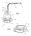
- a humidifying apparatus as might be used in a hospital generally referenced 1 is shown.
- the apparatus comprises a body 2 containing heating means comprising a heating plate 20 having an electric heating element therein or in thermal contact therewith and control means for example electronic circuitry which may include a microprocessor for controlling the supply of energy to the heating element.
- the body 2 is removably engageable with a humidifying chamber 3 which contains water for humidifying gases.
- the humidifying chamber 3 has edges which engage with collar 24 on the humidifier apparatus.
- the gases to be humidified may be a mixture of air, oxygen and anaesthetic for example which are supplied to the chamber through a gases inlet 4.
- a gases outlet 5 is also provided and the gases outlet 5 is connected to the conduit 6 ( Figure 1 ) which conveys humidified gases to a remote destination such as an intubated patient at the end 7 of the conduit.
- the end 7 of the conduit may have a gas mask attached thereto, which mask is used to cover a nose and/or mouth of a user so as to supply humidified gases to the user for breathing, as in the delivery of CPAP therapy.
- the humidifier heater plate 20 has a temperature transducer 8 which is in electrical connection with the electronic control circuitry in body 2 of the apparatus so that the control means monitors the temperature of the heating plate.
- a heating element 10 is provided within the conduit 6 to help prevent condensation of the humidified gases within the conduit. Such condensation is due to the temperature of the walls of the conduit being close to the ambient temperature, (being the temperature of the surrounding atmosphere) which is usually lower than the temperature of the humidified gases within the conduit.
- the heater element is effectively replaces the energy lost from the gases through conduction and convection during transit through the conduit. Thus the conduit heater element ensures the gases delivered are at an optimal temperature and humidity.
- the present invention provides a means of controlling at least the heater plate and preferably also the conduit heater element without the need for any sensors, either in the humidifier chamber or positioned in the conduit. This is achieved by estimating the rate of flow of gases through the humidifier using parameters already available to the controller. For a given humidifier an appropriate level of power can then be determined to apply to the heater plate to achieve the desired temperature of gases delivered to the patient. Additionally this may be used to provide a more appropriate level of energisation at this conduit heater element. This not only saves the cost of the extra sensors but also allows the apparatus connected to the end of the conduit to be simpler and lighter.
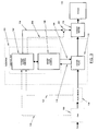
- the controller 100 uses a range of inputs to control both the power 108 supplied to the heater plate 110 as well as the power 114 supplied to the conduit heating element 116 (if present). In certain applications it may also be used to provide control instructions to auxiliary apparatus such as a blower fan. Using an internal algorithm 106 the controller 100 estimates the power 108 to supply to the humidifier heater plate 110 to achieve a given humidity and or temperature of gases at the top of the humidifier chamber alternatively (or estimates the temperature to achieve a given power). It then uses a second algorithm 102 to estimate the required power 114 to supply to the conduit heater element 116 and the humidifier heater plate 110 to achieve optimal temperature and/or humidity of the gases delivered to the patient 118.
- auxiliary apparatus such as a blower fan.
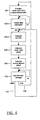
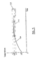
- the controller executes a supervisory algorithm, which controls the heater plate and if present the conduit heater element. Initially 128 the heater plate is controlled to a temperature of 40°C and the conduit heater element may be energised with a duty cycle of for example 50%. The heater plate temperature (or alternatively the power supplied to the heater plate) is then monitored 130 until it settles to a stabilised level. Effectively a window 132 is superimposed over the heater plate temperature profile 134 of which an example is shown in Figure 5 . When the profile 134 (over the entire period of the window 132) fits within the bounds of the window 132, it is effectively considered to have stabilised. Once this has occurred the controller enters a calculation stage.
- the algorithm calculates the required heater plate power 138 (alternatively heater plate temperature) to achieve a desired temperature/humidity of gases (alternatively heater plate power).
- a relationship has been empirically determined using a humidifier and a heated conduit such as that as described in US5640951 . The actual relationship for any other arrangement would either have to be empirically determined by experimentation or theoretically calculated.
- P HP the power supplied to the heater plate
- F gas rate of flow of gases
- T amb ambient temperature
- the algorithm calculates the required power input to the conduit heater wire 140 to deliver a desired temperature of the gases to the patient.
- gases flowing at a known rate of flow it is possible to calculate the resultant temperature of the gases once they have flowed through a conduit of known characteristics surrounded by the atmosphere at a known or assumed ambient temperature.
- Thermal characteristics of the conduit will either be known or can be calculated by experimentation. This relationship is based off empirical data using a humidifier and a heated conduit such as that as described in US5640951 . The actual relationship for any other arrangement would either have to be empirically determined by experimentation or theoretically calculated.
- the controller continues to monitor 142 the system for any changes in the variables.
- the main reason for this is to avoid thermal overshoot ie where the flow drops suddenly, the temperature of gases can become dangerously high.
- the flow rate is monitored and secondly the change in flow rate (with respect to time) is also monitored.
- the first 144 is to allow the system to respond to any changes in the system.
- the second 146 is a fast response system in order to avoid thermal overshoot. Effectively where either P HP or T HP is controlled constant, monitoring the other variable gives an indication of any change in flow, or any other variable which requires a recalculation.
- variable x (defined as P HP /T HP ), which is closely related to the flow rate, is constantly calculated and monitored. If it goes up there is a 30 minute delay before the controller initiates a recalculation, to avoid spurious readings and unnecessary calculations. If it goes down there is a 30 second delay before the controller recalculates, to avoid any possibility of the delivered gases being, even transiently, too hot.
- the heater plate temperature could be controlled to a set value (using closed loop control) as opposed to power.
- the power supplied would be monitored as a measure of system stability.
- relationships are expressed algebraically they could equally be stored in look-up tables.
- a humidifier such as that described in the present invention will be used in conjunction with a respirator to supply humidified gases to an intubated patient, or possibly using a respiratory mask.
- the humidifier will operate effectively independently of the respirator and therefore must make all of its control decisions based on only the sensors contained therein.
- the flow rate of the gases passing through the humidification chamber can first be estimated by comparing the power input required 108 for the humidifier heater plate to the measured temperature 112 of the heater plate. In effect the higher the rate of flow of gases the larger the amount of power required by the heater plate in order to achieve a given heater plate temperature.
- CPAP continuous positive airway pressure
- CPAP continuous positive airway pressure
- the controllers of the various devices may be connected together in an arrangement such that data may be readily exchanged.
- the rate of flow of the gases may be estimated directly from information available either from the fan or, where provided, a flow sensor.
- the flow is estimated based on the loading of the fan.
- the fan will be controlled to run at a specified speed and therefore deliver a constant pressure output.
- the flow rate of the gases will depend on the restrictions in the flow path.
- a certain power input will be required for the fan. Therefore an algebraic relationship between the actual gas flow rate and the power input to the fan can be developed for a fan of known characteristics. This relationship may either be determined empirically by experimentation or theoretically calculated using specified motor characteristics.
- a number of methods are known in the art for determining the loading on a motor from the supply it draws. The simplest such method would be to firstly meter the current drawn 148 from the fan 150, as indicated in Figure 3 .
- the current 148 is the input to the conduit heater element controller 102 where either an algebraic relationship or a look up table is used to determine the flow rate of the gases.
- the gas flow rate 152 can be extracted directly from the flow sensor 154 and used as an input to the humidifier controller 100, as indicated in Figure 3 . This is then used directly in the conduit heater element controller 102 to determine the power to apply to the heater plate 110 and conduit heater element 116 according to the algorithm shown in Figure 4 and described earlier. However, this is outside the scope of the present invention.
- the adaptor 200 includes an indicator 202 to indicate whether the conduit heater element is operating correctly, when the adaptor is plugged in, as shown in Figure 1 .
- the humidifier controller continually detects for the conduit heater element and determines whether it is operating correctly. It does this by energising the conduit heater element intermittently, and if the expected current results it energises 204 the indicator (eg an LED).
- the present invention as described in the foregoing provides a novel method and apparatus for controlling the heater plate temperature in a humidifier for supplying humidified gases to a patient under respiratory therapy. This has the advantage of removing external sensors making the system simpler, cheaper and lighter. Similarly it may also allow for effective control over energisation of the conduit heater element, ensuring the system as a whole operates correctly as well as being as efficient as possible.
Landscapes
- Health & Medical Sciences (AREA)
- Engineering & Computer Science (AREA)
- General Health & Medical Sciences (AREA)
- Public Health (AREA)
- Anesthesiology (AREA)
- Biomedical Technology (AREA)
- Heart & Thoracic Surgery (AREA)
- Hematology (AREA)
- Life Sciences & Earth Sciences (AREA)
- Animal Behavior & Ethology (AREA)
- Emergency Medicine (AREA)
- Pulmonology (AREA)
- Veterinary Medicine (AREA)
- Physics & Mathematics (AREA)
- General Physics & Mathematics (AREA)
- Automation & Control Theory (AREA)
- Air Humidification (AREA)
- Control Of Non-Electrical Variables (AREA)
- Air Conditioning Control Device (AREA)
- Respiratory Apparatuses And Protective Means (AREA)
Abstract
Claims (9)
- Appareil d'assistance respiratoire conçu pour délivrer des gaz humidifiés à un niveau souhaité d'humidité ou à une température souhaitée, l'appareil comprenant :des moyens d'humidification (1) comprenant une chambre d'humidification (3) conçue pour recevoir un volume d'eau et des moyens (20) de chauffage d'eau qui chauffent ladite eau pour produire en utilisation de la vapeur d'eau dans ladite chambre, lesdits gaz qui traversent ladite vapeur d'eau présente dans ladite chambre étant de cette façon humidifiés,lesdits moyens d'humidification recevant de l'énergie électrique et étant capables d'humidifier lesdits gaz jusqu'à un niveau d'humidité qui dépend de ladite énergie introduite dans lesdits moyens d'humidification etdes moyens (8) de détection de la chambre fournissant une indication de la température desdits moyens (20) de chauffage de l'eau et fournissant une indication de l'énergie électrique prélevée par lesdits moyens de chauffage de l'eau
caractérisé pardes moyens de contrôle (100) dans lesquels sont enregistrées des instructions permettant de :(a) déterminer un paramètre lié au débit desdits gaz dans ledit appareil, lesdites instructions (a) comprenant les étapes qui consistent à :i) alimenter lesdits moyens de chauffage pour chauffer ladite eau jusqu'à un premier état,ii) surveiller en continu une variable indicatrice d'une propriété desdits moyens de chauffage de l'eau jusqu'à ce que ladite variable indique que ladite eau a essentiellement atteint le premier état, ladite variable étant indicatrice de ladite indication de la température desdits moyens de chauffage ou de ladite indication de l'énergie prélevée par lesdits moyens de chauffage de l'eau etiii) déterminer ledit paramètre au moins sur la base de ladite variable,(b) déterminer au moins sur la base dudit paramètre la quantité d'énergie électrique requise pour que lesdits moyens d'humidification puissent délivrer lesdits gaz à un niveau d'humidité ou à une température essentiellement similaires audit niveau souhaité d'humidité ou à ladite température souhaitée et(c) délivrer auxdits moyens d'humidification ladite énergie à un niveau essentiellement similaire à ladite quantité d'énergie déterminée comme devant être délivrée auxdits moyens d'humidification. - Appareil d'assistance respiratoire selon la revendication 1, comprenant de plus des moyens (6) de parcours de transport qui transfèrent à un patient lesdits gaz humidifiés par lesdits moyens d'humidification.
- Appareil d'assistance respiratoire selon la revendication 2, comprenant de plus :des moyens (10) de chauffage de parcours aptes à recevoir de l'énergie électrique et associés auxdits moyens (6) de parcours de transport, les gaz s'écoulant dans lesdits moyens de parcours de transport étant chauffés directement ou indirectement par lesdits moyens de chauffage de parcours, le niveau de chauffage dépendant de ladite énergie délivrée auxdits moyens de chauffage de parcours, etun capteur de température ambiante fournissant l'indication de la température extérieure,ladite instruction (b) comprenant de plus une instruction permettant de déterminer sur la base d'au moins ladite indication de la température extérieure l'énergie qui doit être délivrée auxdits moyens de chauffage de parcours pour délivrer audit patient ledit gaz à un niveau d'humidité ou à une température essentiellement similaires audit niveau d'humidité ou à ladite température souhaités,ladite instruction (c) comprenant de plus une instruction d'apport de ladite énergie auxdits moyens de chauffage de parcours à un niveau essentiellement similaire à ladite quantité d'énergie déterminée comme devant être délivrée auxdits moyens de chauffage de parcours.
- Appareil d'assistance respiratoire selon la revendication 3, comprenant de plus la détermination de ladite énergie auxdits moyens d'humidification au cours de l'instruction (b) sur la base de ladite indication de la température extérieure.
- Appareil d'assistance respiratoire selon la revendication 3, dans lequel lesdits moyens de contrôle enregistrent une instruction supplémentaire qui permet de :(d) surveiller en continu ledit paramètre ou ladite variable et revenir à ladite instruction (b) lorsqu'un changement dudit paramètre ou de ladite variable est plus grand qu'une première valeur de seuil et revenir à l'instruction (a) lorsqu'un changement dudit paramètre ou de ladite variable est plus grand qu'une deuxième valeur de seuil, la deuxième valeur de seuil étant plus grande que la première valeur de seuil.
- Appareil d'assistance respiratoire selon la revendication 5, dans lequel si ledit changement dudit paramètre ou de ladite variable est indicatif d'une diminution du débit, un retard de temps relativement court est induit avant que lesdits moyens de contrôle reviennent à ladite instruction (b) et si le changement est indicatif d'une augmentation du débit, un délai de durée relativement longue est induit avant que lesdits moyens de contrôle reviennent à ladite instruction (b).
- Appareil d'assistance respiratoire selon la revendication 6, dans lequel la deuxième valeur de seuil est basée sur le taux de changement dudit paramètre ou de ladite variable en fonction du temps et dans lequel lesdits moyens de contrôle reviennent à ladite instruction (a) lorsque ledit taux de changement est supérieur à ladite deuxième valeur de seuil.
- Appareil d'assistance respiratoire selon l'une quelconque des revendications précédentes, comprenant des moyens d'approvisionnement en gaz conçus pour effectuer l'approvisionnement en gaz dudit moyen d'humidification à une pression requise et au débit qui en résulte.
- Appareil d'assistance respiratoire selon la revendication 8, dans lequel lesdits moyens d'approvisionnement en gaz comprennent une soufflante (150) entraînée par un moteur électrique à vitesse variable.
Applications Claiming Priority (3)
| Application Number | Priority Date | Filing Date | Title |
|---|---|---|---|
| NZ33738299 | 1999-08-23 | ||
| NZ33738299 | 1999-08-23 | ||
| PCT/NZ2000/000156 WO2001013981A1 (fr) | 1999-08-23 | 2000-08-09 | Controleur d'humidite |
Publications (3)
| Publication Number | Publication Date |
|---|---|
| EP1207929A1 EP1207929A1 (fr) | 2002-05-29 |
| EP1207929A4 EP1207929A4 (fr) | 2006-03-08 |
| EP1207929B1 true EP1207929B1 (fr) | 2012-05-30 |
Family
ID=19927464
Family Applications (1)
| Application Number | Title | Priority Date | Filing Date |
|---|---|---|---|
| EP00955190A Expired - Lifetime EP1207929B1 (fr) | 1999-08-23 | 2000-08-09 | Controleur d'humidité |
Country Status (13)
| Country | Link |
|---|---|
| EP (1) | EP1207929B1 (fr) |
| JP (1) | JP4928035B2 (fr) |
| KR (1) | KR100500761B1 (fr) |
| CN (1) | CN1230221C (fr) |
| AR (1) | AR026153A1 (fr) |
| AU (1) | AU776699B2 (fr) |
| BR (1) | BR0013570B1 (fr) |
| CA (1) | CA2391787C (fr) |
| MX (1) | MXPA02001881A (fr) |
| MY (1) | MY130263A (fr) |
| UY (1) | UY26305A1 (fr) |
| WO (1) | WO2001013981A1 (fr) |
| ZA (1) | ZA200201124B (fr) |
Families Citing this family (38)
| Publication number | Priority date | Publication date | Assignee | Title |
|---|---|---|---|---|
| DE10139881B4 (de) | 2001-08-20 | 2017-06-08 | Resmed R&D Germany Gmbh | Vorrichtung zur Zufuhr eines Atemgases und Verfahren zur Steuerung derselben |
| JP4709547B2 (ja) * | 2002-08-30 | 2011-06-22 | フィッシャー アンド ペイケル ヘルスケア リミテッド | 加湿システム |
| JP2006504469A (ja) | 2002-11-01 | 2006-02-09 | フィッシャー アンド ペイケル ヘルスケア リミテッド | 患者へのガス送出を検出するシステム |
| NZ553013A (en) | 2004-08-10 | 2010-12-24 | Resmed Ltd | Method and apparatus for humidification of breathable gas with profiled varying humidity setting delivery |
| HUE060036T2 (hu) | 2004-08-20 | 2023-01-28 | Fisher & Paykel Healthcare Ltd | Berendezés páciensnek szállított gázok tulajdonságainak mérésére |
| CN101252966B (zh) | 2005-05-26 | 2012-07-18 | 菲舍尔和佩克尔保健有限公司 | 呼吸辅助设备 |
| WO2007019628A1 (fr) | 2005-08-15 | 2007-02-22 | Resmed Ltd | Ensemble generateur de flux de ventilation spontanee en pression positive continue et humidificateur a bas prix |
| DE102006019402A1 (de) * | 2006-04-24 | 2007-10-25 | Seleon Gmbh | Verfahren zur Steuerung eines TNI-Geräts sowie TNI-Gerät |
| CN110141752B (zh) | 2006-11-08 | 2022-03-04 | 瑞思迈私人有限公司 | 在呼吸装置中使用的导管 |
| CN101220988B (zh) * | 2007-01-12 | 2010-09-29 | 雃博股份有限公司 | 呼吸治疗器加热盘总成 |
| DE102007015038B3 (de) * | 2007-02-08 | 2008-03-27 | Dräger Medical AG & Co. KG | Vorrichtung und Verfahren zum Bereitstellen von angefeuchtetem Atemgas |
| US8063343B2 (en) * | 2007-10-29 | 2011-11-22 | Smiths Medical Asd, Inc. | Heated breathing circuit detection |
| US8511305B2 (en) | 2007-10-29 | 2013-08-20 | Smiths Medical Asd, Inc. | Redundant power control for respiratory system heaters |
| US9802022B2 (en) | 2008-03-06 | 2017-10-31 | Resmed Limited | Humidification of respiratory gases |
| CN113425974A (zh) * | 2008-03-06 | 2021-09-24 | 瑞思迈私人有限公司 | 呼吸气体的湿化 |
| EP3756719B1 (fr) | 2008-05-27 | 2024-01-24 | Fisher & Paykel Healthcare Limited | Système d'assistance respiratoire pour l'administration de gaz |
| WO2010016838A1 (fr) * | 2008-08-06 | 2010-02-11 | Ric Investments, Llc | Système et procédé de détermination de l'humidité dans un système de traitement respiratoire |
| EP3632492A1 (fr) | 2008-09-10 | 2020-04-08 | ResMed Pty Ltd | Gestion de puissance améliorée dans un appareil de traitement respiratoire |
| PL2248547T3 (pl) * | 2009-05-05 | 2013-01-31 | Plastiflex Group | Układ obwodu oddychania |
| AU2010206053B2 (en) | 2009-07-31 | 2014-08-07 | ResMed Pty Ltd | Wire Heated Tube with Temperature Control System, Tube Type Detection, and Active Over Temperature Protection for Humidifier for Respiratory Apparatus |
| US9572951B2 (en) | 2010-04-27 | 2017-02-21 | Fisher & Paykel Healthcare Limited | Apparatus for supplying gases to a patient |
| EP2575944B1 (fr) | 2010-06-04 | 2017-02-22 | Koninklijke Philips N.V. | Régulation automatique de la température dans un circuit patient |
| JP2014506486A (ja) | 2011-01-24 | 2014-03-17 | レスメド・リミテッド | 加湿器 |
| US8511651B2 (en) * | 2011-03-29 | 2013-08-20 | Smiths Medical Asd, Inc. | Heater unit humidification chamber monitor |
| US10806878B2 (en) * | 2012-02-22 | 2020-10-20 | Koninklijke Philips N.V. | System and method for determining a target subject interface temperature based on a baseline temperature |
| US9878123B2 (en) | 2012-09-11 | 2018-01-30 | Fisher & Paykel Healthcare Limited | Surgical humidifier control |
| AU2012216775B2 (en) * | 2012-09-12 | 2018-06-28 | Fisher & Paykel Healthcare Limited | Surgical humidifier control |
| NZ727820A (en) | 2013-02-01 | 2018-06-29 | Resmed Ltd | Wire heated tube with temperature control system for humidifier for respiratory apparatus |
| DK2770047T3 (en) * | 2013-02-26 | 2015-06-29 | Ibidi Gmbh | Device for obtaining a gas |
| MX2013014220A (es) * | 2013-12-04 | 2015-06-03 | Investigación Y Desarrollo En Equipo Médico S A De C V | Dispositivo de control de potencia suministrada a plato de camara de humidificacion y elemento de calentamiento de tubo, y metodo de control. |
| GB2585142B (en) | 2014-04-16 | 2021-03-24 | Fisher & Paykel Healthcare Ltd | Methods and systems for delivering gas to a patient |
| JP6411263B2 (ja) * | 2015-03-27 | 2018-10-24 | オリンパス株式会社 | 気腹装置、気腹装置の作動方法 |
| GB2539222B (en) * | 2015-06-09 | 2019-03-06 | Intersurgical Ag | Humidifier flow determination |
| WO2017126980A2 (fr) | 2016-01-18 | 2017-07-27 | Fisher & Paykel Healthcare Limited | Humidification de gaz respiratoires |
| JP7177837B2 (ja) | 2017-12-19 | 2022-11-24 | コーニンクレッカ フィリップス エヌ ヴェ | 低温通過加湿制御を行う換気システム |
| CN111150917B (zh) * | 2019-12-31 | 2021-09-14 | 北京怡和嘉业医疗科技股份有限公司 | 一种通气治疗设备湿化控制系统和方法 |
| CN113679924B (zh) * | 2021-08-30 | 2024-01-02 | 可孚医疗科技股份有限公司 | 一种用于呼吸设备的加湿水箱的水温控制方法及相应装置 |
| CN116672556A (zh) * | 2023-07-25 | 2023-09-01 | 湖南比扬医疗科技有限公司 | 呼吸机输出功率的控制方法、装置、呼吸机及存储介质 |
Family Cites Families (17)
| Publication number | Priority date | Publication date | Assignee | Title |
|---|---|---|---|---|
| GB1294808A (en) * | 1971-08-19 | 1972-11-01 | Philips Electronic Associated | Temperature-controlled gas humidifier for a medical ventilator |
| US4682010A (en) * | 1983-03-07 | 1987-07-21 | Safeway Products, Inc. | In-line electric heater for an aerosol delivery system |
| US4621632A (en) * | 1984-11-01 | 1986-11-11 | Bear Medical Systems, Inc. | Humidifier system |
| GB2192136B (en) * | 1986-07-04 | 1991-01-02 | Virotherm Lab Ltd | Medical breathing apparatus |
| US5031612A (en) * | 1990-04-24 | 1991-07-16 | Devilbiss Health Care, Inc. | System and method for delivering warm humidified air |
| EP0535952B1 (fr) * | 1991-10-04 | 1997-12-29 | FISHER & PAYKEL LIMITED | Humidificateur |
| JP2654887B2 (ja) * | 1992-05-22 | 1997-09-17 | 将秀 大塚 | 結露センサー付加温加湿器 |
| DE4310855C2 (de) * | 1993-04-02 | 1995-04-27 | Josef Dr Klimm | Einrichtung zur Überwachung wenigstens einer Verbindung zwischen zwei Elementen eines medizinischen Schlauchleitungssystems |
| AUPM279393A0 (en) | 1993-12-03 | 1994-01-06 | Rescare Limited | Estimation of flow and detection of breathing in cpap treatment |
| AU1486395A (en) * | 1994-03-15 | 1995-09-21 | Fisher & Paykel Limited | Respiratory air supply system with airflow dependent humidity |
| AU1486195A (en) | 1994-03-15 | 1995-09-21 | Fisher & Paykel Limited | A humidifier conduit |
| AUPN547895A0 (en) * | 1995-09-15 | 1995-10-12 | Rescare Limited | Flow estimation and compenstion of flow-induced pressure swings cpap treatment |
| CA2222830C (fr) * | 1996-12-02 | 2004-03-30 | Fisher & Paykel Limited | Appareil de traitement d'apnee obstructive du sommeil |
| CA2240812C (fr) * | 1997-06-17 | 2004-06-01 | Fisher & Paykel Limited | Systeme d'humidification pour appareillage respiratoire |
| AU3508799A (en) * | 1998-06-19 | 2000-01-06 | Fisher & Paykel Healthcare Limited | Humidified sleep apnea treatment apparatus |
| ES2251416T3 (es) * | 1999-12-10 | 2006-05-01 | Vapotherm, Inc. | Aparato para terapia del tracto respiratorio. |
| SE0000605D0 (sv) * | 2000-02-24 | 2000-02-24 | Siemens Elema Ab | Conduit for connecting a fluid transfer device to a patient |
-
2000
- 2000-08-09 AU AU67422/00A patent/AU776699B2/en not_active Expired
- 2000-08-09 EP EP00955190A patent/EP1207929B1/fr not_active Expired - Lifetime
- 2000-08-09 KR KR10-2002-7002381A patent/KR100500761B1/ko active IP Right Grant
- 2000-08-09 WO PCT/NZ2000/000156 patent/WO2001013981A1/fr active IP Right Grant
- 2000-08-09 JP JP2001518113A patent/JP4928035B2/ja not_active Expired - Lifetime
- 2000-08-09 BR BRPI0013570-4A patent/BR0013570B1/pt not_active IP Right Cessation
- 2000-08-09 MX MXPA02001881A patent/MXPA02001881A/es active IP Right Grant
- 2000-08-09 CA CA2391787A patent/CA2391787C/fr not_active Expired - Lifetime
- 2000-08-09 CN CNB008118922A patent/CN1230221C/zh not_active Expired - Lifetime
- 2000-08-18 UY UY26305A patent/UY26305A1/es not_active Application Discontinuation
- 2000-08-22 MY MYPI20003855A patent/MY130263A/en unknown
- 2000-08-22 AR ARP000104339A patent/AR026153A1/es active IP Right Grant
-
2002
- 2002-02-08 ZA ZA200201124A patent/ZA200201124B/xx unknown
Also Published As
| Publication number | Publication date |
|---|---|
| KR100500761B1 (ko) | 2005-07-12 |
| AU6742200A (en) | 2001-03-19 |
| JP4928035B2 (ja) | 2012-05-09 |
| EP1207929A1 (fr) | 2002-05-29 |
| BR0013570B1 (pt) | 2009-01-13 |
| JP2003507138A (ja) | 2003-02-25 |
| ZA200201124B (en) | 2003-07-30 |
| CA2391787C (fr) | 2010-10-05 |
| CN1370085A (zh) | 2002-09-18 |
| UY26305A1 (es) | 2001-01-31 |
| BR0013570A (pt) | 2002-06-11 |
| EP1207929A4 (fr) | 2006-03-08 |
| MXPA02001881A (es) | 2003-07-21 |
| KR20020042651A (ko) | 2002-06-05 |
| CA2391787A1 (fr) | 2001-03-01 |
| AU776699B2 (en) | 2004-09-16 |
| AR026153A1 (es) | 2003-01-29 |
| WO2001013981A1 (fr) | 2001-03-01 |
| MY130263A (en) | 2007-06-29 |
| CN1230221C (zh) | 2005-12-07 |
Similar Documents
| Publication | Publication Date | Title |
|---|---|---|
| EP1207929B1 (fr) | Controleur d'humidité | |
| US7106955B2 (en) | Humidity controller | |
| US9186477B2 (en) | Humidity controller | |
| US20190030276A1 (en) | Humidity controller | |
| US11129957B2 (en) | Humidified gases delivery apparatus and methods for controlling same | |
| US11679227B2 (en) | Water out alarm | |
| EP1542756B1 (fr) | Systeme d'humidification | |
| US20230166064A1 (en) | Respiratory or surgical humidifier and method of use | |
| AU785254B2 (en) | Humidity controller |
Legal Events
| Date | Code | Title | Description |
|---|---|---|---|
| PUAI | Public reference made under article 153(3) epc to a published international application that has entered the european phase |
Free format text: ORIGINAL CODE: 0009012 |
|
| 17P | Request for examination filed |
Effective date: 20020212 |
|
| AK | Designated contracting states |
Kind code of ref document: A1 Designated state(s): AT BE CH CY DE DK ES FI FR GB GR IE IT LI LU MC NL PT SE |
|
| AX | Request for extension of the european patent |
Free format text: AL;LT;LV;MK;RO;SI |
|
| A4 | Supplementary search report drawn up and despatched |
Effective date: 20060120 |
|
| R17C | First examination report despatched (corrected) |
Effective date: 20060724 |
|
| GRAP | Despatch of communication of intention to grant a patent |
Free format text: ORIGINAL CODE: EPIDOSNIGR1 |
|
| RTI1 | Title (correction) |
Free format text: HUMIDITY CONTROLLER |
|
| GRAS | Grant fee paid |
Free format text: ORIGINAL CODE: EPIDOSNIGR3 |
|
| GRAA | (expected) grant |
Free format text: ORIGINAL CODE: 0009210 |
|
| AK | Designated contracting states |
Kind code of ref document: B1 Designated state(s): AT BE CH CY DE DK ES FI FR GB GR IE IT LI LU MC NL PT SE |
|
| REG | Reference to a national code |
Ref country code: GB Ref legal event code: FG4D |
|
| REG | Reference to a national code |
Ref country code: CH Ref legal event code: EP |
|
| REG | Reference to a national code |
Ref country code: AT Ref legal event code: REF Ref document number: 559742 Country of ref document: AT Kind code of ref document: T Effective date: 20120615 |
|
| REG | Reference to a national code |
Ref country code: IE Ref legal event code: FG4D |
|
| REG | Reference to a national code |
Ref country code: DE Ref legal event code: R096 Ref document number: 60047234 Country of ref document: DE Effective date: 20120719 |
|
| REG | Reference to a national code |
Ref country code: NL Ref legal event code: VDEP Effective date: 20120530 |
|
| PG25 | Lapsed in a contracting state [announced via postgrant information from national office to epo] |
Ref country code: SE Free format text: LAPSE BECAUSE OF FAILURE TO SUBMIT A TRANSLATION OF THE DESCRIPTION OR TO PAY THE FEE WITHIN THE PRESCRIBED TIME-LIMIT Effective date: 20120530 Ref country code: CY Free format text: LAPSE BECAUSE OF FAILURE TO SUBMIT A TRANSLATION OF THE DESCRIPTION OR TO PAY THE FEE WITHIN THE PRESCRIBED TIME-LIMIT Effective date: 20120530 Ref country code: FI Free format text: LAPSE BECAUSE OF FAILURE TO SUBMIT A TRANSLATION OF THE DESCRIPTION OR TO PAY THE FEE WITHIN THE PRESCRIBED TIME-LIMIT Effective date: 20120530 |
|
| REG | Reference to a national code |
Ref country code: AT Ref legal event code: MK05 Ref document number: 559742 Country of ref document: AT Kind code of ref document: T Effective date: 20120530 |
|
| PG25 | Lapsed in a contracting state [announced via postgrant information from national office to epo] |
Ref country code: GR Free format text: LAPSE BECAUSE OF FAILURE TO SUBMIT A TRANSLATION OF THE DESCRIPTION OR TO PAY THE FEE WITHIN THE PRESCRIBED TIME-LIMIT Effective date: 20120831 |
|
| PG25 | Lapsed in a contracting state [announced via postgrant information from national office to epo] |
Ref country code: BE Free format text: LAPSE BECAUSE OF FAILURE TO SUBMIT A TRANSLATION OF THE DESCRIPTION OR TO PAY THE FEE WITHIN THE PRESCRIBED TIME-LIMIT Effective date: 20120530 |
|
| PG25 | Lapsed in a contracting state [announced via postgrant information from national office to epo] |
Ref country code: NL Free format text: LAPSE BECAUSE OF FAILURE TO SUBMIT A TRANSLATION OF THE DESCRIPTION OR TO PAY THE FEE WITHIN THE PRESCRIBED TIME-LIMIT Effective date: 20120530 Ref country code: DK Free format text: LAPSE BECAUSE OF FAILURE TO SUBMIT A TRANSLATION OF THE DESCRIPTION OR TO PAY THE FEE WITHIN THE PRESCRIBED TIME-LIMIT Effective date: 20120530 Ref country code: AT Free format text: LAPSE BECAUSE OF FAILURE TO SUBMIT A TRANSLATION OF THE DESCRIPTION OR TO PAY THE FEE WITHIN THE PRESCRIBED TIME-LIMIT Effective date: 20120530 |
|
| PG25 | Lapsed in a contracting state [announced via postgrant information from national office to epo] |
Ref country code: PT Free format text: LAPSE BECAUSE OF FAILURE TO SUBMIT A TRANSLATION OF THE DESCRIPTION OR TO PAY THE FEE WITHIN THE PRESCRIBED TIME-LIMIT Effective date: 20121001 Ref country code: IT Free format text: LAPSE BECAUSE OF FAILURE TO SUBMIT A TRANSLATION OF THE DESCRIPTION OR TO PAY THE FEE WITHIN THE PRESCRIBED TIME-LIMIT Effective date: 20120530 |
|
| REG | Reference to a national code |
Ref country code: CH Ref legal event code: PL |
|
| PG25 | Lapsed in a contracting state [announced via postgrant information from national office to epo] |
Ref country code: MC Free format text: LAPSE BECAUSE OF NON-PAYMENT OF DUE FEES Effective date: 20120831 |
|
| PLBE | No opposition filed within time limit |
Free format text: ORIGINAL CODE: 0009261 |
|
| STAA | Information on the status of an ep patent application or granted ep patent |
Free format text: STATUS: NO OPPOSITION FILED WITHIN TIME LIMIT |
|
| PG25 | Lapsed in a contracting state [announced via postgrant information from national office to epo] |
Ref country code: ES Free format text: LAPSE BECAUSE OF FAILURE TO SUBMIT A TRANSLATION OF THE DESCRIPTION OR TO PAY THE FEE WITHIN THE PRESCRIBED TIME-LIMIT Effective date: 20120910 Ref country code: LI Free format text: LAPSE BECAUSE OF NON-PAYMENT OF DUE FEES Effective date: 20120831 Ref country code: CH Free format text: LAPSE BECAUSE OF NON-PAYMENT OF DUE FEES Effective date: 20120831 |
|
| 26N | No opposition filed |
Effective date: 20130301 |
|
| REG | Reference to a national code |
Ref country code: IE Ref legal event code: MM4A |
|
| REG | Reference to a national code |
Ref country code: DE Ref legal event code: R097 Ref document number: 60047234 Country of ref document: DE Effective date: 20130301 |
|
| PG25 | Lapsed in a contracting state [announced via postgrant information from national office to epo] |
Ref country code: IE Free format text: LAPSE BECAUSE OF NON-PAYMENT OF DUE FEES Effective date: 20120809 |
|
| PG25 | Lapsed in a contracting state [announced via postgrant information from national office to epo] |
Ref country code: LU Free format text: LAPSE BECAUSE OF NON-PAYMENT OF DUE FEES Effective date: 20120809 |
|
| REG | Reference to a national code |
Ref country code: FR Ref legal event code: PLFP Year of fee payment: 17 |
|
| REG | Reference to a national code |
Ref country code: FR Ref legal event code: PLFP Year of fee payment: 18 |
|
| REG | Reference to a national code |
Ref country code: FR Ref legal event code: PLFP Year of fee payment: 19 |
|
| PGFP | Annual fee paid to national office [announced via postgrant information from national office to epo] |
Ref country code: FR Payment date: 20190827 Year of fee payment: 20 |
|
| PGFP | Annual fee paid to national office [announced via postgrant information from national office to epo] |
Ref country code: GB Payment date: 20190829 Year of fee payment: 20 |
|
| PGFP | Annual fee paid to national office [announced via postgrant information from national office to epo] |
Ref country code: DE Payment date: 20191031 Year of fee payment: 20 |
|
| REG | Reference to a national code |
Ref country code: DE Ref legal event code: R071 Ref document number: 60047234 Country of ref document: DE |
|
| REG | Reference to a national code |
Ref country code: GB Ref legal event code: PE20 Expiry date: 20200808 |
|
| PG25 | Lapsed in a contracting state [announced via postgrant information from national office to epo] |
Ref country code: GB Free format text: LAPSE BECAUSE OF EXPIRATION OF PROTECTION Effective date: 20200808 |