EP1206407B1 - Method and device for transferring at least two overlapped sheets to a sheet-handling machine - Google Patents
Method and device for transferring at least two overlapped sheets to a sheet-handling machine Download PDFInfo
- Publication number
- EP1206407B1 EP1206407B1 EP00949482A EP00949482A EP1206407B1 EP 1206407 B1 EP1206407 B1 EP 1206407B1 EP 00949482 A EP00949482 A EP 00949482A EP 00949482 A EP00949482 A EP 00949482A EP 1206407 B1 EP1206407 B1 EP 1206407B1
- Authority
- EP
- European Patent Office
- Prior art keywords
- sheet
- sheets
- speed
- transport unit
- transport direction
- Prior art date
- Legal status (The legal status is an assumption and is not a legal conclusion. Google has not performed a legal analysis and makes no representation as to the accuracy of the status listed.)
- Expired - Lifetime
Links
Images


Classifications
-
- B—PERFORMING OPERATIONS; TRANSPORTING
- B65—CONVEYING; PACKING; STORING; HANDLING THIN OR FILAMENTARY MATERIAL
- B65H—HANDLING THIN OR FILAMENTARY MATERIAL, e.g. SHEETS, WEBS, CABLES
- B65H33/00—Forming counted batches in delivery pile or stream of articles
- B65H33/12—Forming counted batches in delivery pile or stream of articles by creating gaps in the stream
-
- B—PERFORMING OPERATIONS; TRANSPORTING
- B65—CONVEYING; PACKING; STORING; HANDLING THIN OR FILAMENTARY MATERIAL
- B65H—HANDLING THIN OR FILAMENTARY MATERIAL, e.g. SHEETS, WEBS, CABLES
- B65H29/00—Delivering or advancing articles from machines; Advancing articles to or into piles
- B65H29/66—Advancing articles in overlapping streams
- B65H29/6654—Advancing articles in overlapping streams changing the overlapping figure
-
- B—PERFORMING OPERATIONS; TRANSPORTING
- B65—CONVEYING; PACKING; STORING; HANDLING THIN OR FILAMENTARY MATERIAL
- B65H—HANDLING THIN OR FILAMENTARY MATERIAL, e.g. SHEETS, WEBS, CABLES
- B65H2301/00—Handling processes for sheets or webs
- B65H2301/40—Type of handling process
- B65H2301/44—Moving, forwarding, guiding material
- B65H2301/445—Moving, forwarding, guiding material stream of articles separated from each other
- B65H2301/4454—Merging two or more streams
-
- B—PERFORMING OPERATIONS; TRANSPORTING
- B65—CONVEYING; PACKING; STORING; HANDLING THIN OR FILAMENTARY MATERIAL
- B65H—HANDLING THIN OR FILAMENTARY MATERIAL, e.g. SHEETS, WEBS, CABLES
- B65H2511/00—Dimensions; Position; Numbers; Identification; Occurrences
- B65H2511/20—Location in space
- B65H2511/22—Distance
Definitions
- the present invention relates to a method and a device for taking over at least two, in one Sheet or paper running direction arranged in shingles Scrolling into a sheet or paper handling machine, in which the at least two sheets after the takeover with one first speed to be moved.
- Paper handling systems are known in the prior art, where, for example, 2-use printed sheets one Cutting machine are fed, separated by this are provided, and subsequent processing become.
- the 2-up are printed Sheets using suitable machines, e.g. mergers, placed on top of each other and thus lie for further processing on subsequent paper handling machines.
- Sheets take over the following machines, per machine cycle, a sheet provided, depending on the downstream machines, for example from the provided Scroll individual groups are formed must then be inserted, for example.
- the cycle with which the cutting machine works and with which the individual sheets to the subsequent machines provided is higher than the clock cycle of one subsequent inserter. Let’s take as an example that the cutting machine for a fixed period of time Can cut 1000 times while the inserter 100 times can insert. This leads to a first Case in which the inserter only processes single sheets, the cutting machine is stopped regularly because there are too many Leaves would be provided by this, whereas in a second case, in which the inserter fifteen Sheets inserted, the inserter stopped regularly must be because the cutting machine is not sufficient can provide many sheets.
- the individual from the cutting machine output sheets entered into the buffer, and after reaching a predetermined number of sheets, e.g. switched to a second buffer level, so that the in the first buffer level contain sheets of further processing can be fed while simultaneously in the second buffer sheets output from the cutting machine can be entered.
- a predetermined number of sheets e.g. switched to a second buffer level
- Such a device is for example in U.S. Patent 5,083,769.
- US-A-4,040,617 relates to a sheet overlap device which between a fast and a slow conveyor is positioned to sheets from the fast conveyor slow down and the same on an overlapping Way to transfer into the slow conveyor. It describes a sheet overlap device that is slightly different from each other separately arranged sheets by a cutter be fed from the quick to the slow conveyor transferred. The takeover of in a sheet running direction is arranged overlapping sheets not described.
- the present Invention based on the object, a method and a To create device that is simple and accelerated Group formation with a minimum number of required Support machine clocks in paper handling systems.
- the present invention provides an apparatus for transferring at least two sheets that are shingled in a sheet travel direction into a sheet handling machine, which comprises a transport unit that moves the at least two sheets after transfer at a first speed, a first sheet and a second sheet of the at least two sheets are offset by an offset in the paper travel direction an infeed roller which feeds the at least two sheets of the sheet handling machine at a second speed, the second speed being higher than the first speed; and a brake roller which brakes the second sheet to a third speed as soon as the first sheet is braked by the transport unit, the third speed being lower than the second speed.
- the present invention is based on the finding that that by the advancement of the invention to be processed Leaves the disadvantages described above in the prior art Technology can be overcome by the 2-way printed Leaves superimposed with a small longitudinal offset become, i.e. the leaves are scaled so that these are easy to separate later. In a simple way and In this way, larger groups can be formed by using further, already pre-scaled leaves, a larger one Scale flow is formed.
- the known in the prior art Machines enable such an approach not, but only allow the formation of the shingled stream from single sheets or with non-offset double benefit.
- the present invention has the advantage that by the inventive method and the inventive Device for taking over in one cycle at least two leaves that are already shingled into one Paper handling machine can be taken over without that, as would be the case with the prior art, they were scaled Leaves would slide together again. According to the invention this problem is solved in that the leading Sheet on the leading edge of the sheet and the trailing one Leaf at the rear edge of the leaf is braked.
- the first speed is equal to the third speed.
- the thus formed is then transported onward Group and the resulting scale flow by one Distance equal to the number of sheets in the group times the scale length, moving to a subsequent one Transport takes place, which then takes over the group.
- a further transport unit is additionally provided, to which the in the first transport unit continuously collected and flaked leaves Reaching a predetermined number of sheets in the first Transport unit will be handed over, the second Transport unit depending on the number of items to be output Scrolling is moved clocked, so that the stored therein Shingled stream is moved towards an output unit, where on the output unit each in the paper travel direction front sheet output from the paper handling machine becomes.
- the advantage of the present invention is that this is a continuous inflow of the merged leaves enables and with it a high performance increase.
- a process that involves the provision of at least allows two leaves in a scaly shape is in described in DE 199 35 186 A.
- the present invention enables the operation of a paper handling machine with medium group sizes, the number of leaves per Groups between which the above limits lie a precursor machine (e.g. cutting machine) or one Follower machine (e.g. inserter) must be stopped.
- a precursor machine e.g. cutting machine
- one Follower machine e.g. inserter
- FIG. 1 schematically shows an example of a paper handling system shown, which is essentially four separate Sections A - D includes.
- Section A of the paper handling system becomes 2-use printed sheets 100 fed to a cutting machine, and the paper web is cut lengthways and crossways around the cut sheets 100a and 100b, which are described in section B are merged in such a way that the Leaves 100a and 100b are arranged in shingled relationship thus in a sheet or paper running direction P by a predetermined Offset (scale length) X are shifted.
- the merger section B the two are arranged in shingles Pass sheets 100a and 100b to section C, in which the fed sheets are cached before in section D e.g. passed on to a collecting station become.
- Section C is divided into sections C1 and C2, wherein section C1 is a section of the sheet handling machine represents, which is based on 3 is described in more detail. Section C2 also provides a section of the paper handling machine , which are described in more detail below using the Fig. 5 is described. Section C presents in its Taken as a whole, the paper handling machine described later in FIG. 6 represents.
- section C1 the scaly leaves are arranged 100a and 100b continuously fed until a predetermined one Number is reached, and then the one so formed Scale flow in a single cycle to section C2 transferred from which, then, clocked, single sheets or Groups of sheets are fed to the collecting station, such as this will be described in detail later.
- Group 1 is shown as an example in section A and B, like single sheets or groups of sheets in the double benefit are arranged. Leaves belonging to the same group are labeled with the same lowercase letters.
- the Group a comprises only one sheet, which comprises group b two sheets, and group c comprises three sheets.
- the present invention works from already scaled leaves, whereby in the following description of the invention Method and the device according to the invention first for the sake of simplicity, it is assumed that only two flaky leaves are to be taken over.
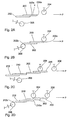
- FIG. 2A The situation is illustrated schematically in FIG. 2A, in which is a first sheet 200 and a second sheet 202 in one Direction of paper or sheet of a direction not shown in detail Paper handling machine can be fed. How to the first sheet is 200 and the second sheet 202 in the paper running direction P by the one already described Offset X arranged shifted, so have a scale length X on that in a preferred embodiment 20 mm, but are in the range of 10 mm to 50 mm can.
- the offset X or the scale length X is defined by the distance of the front edge 200a in the paper running direction P of the first sheet 200 to the front in the paper running direction P. Edge 202a of the second sheet.
- Fig. 2a is also schematically a first scale roll 204 depicted with respect to sheets 200 and 202 is arranged.
- the scale roll 204 is part of a first transport unit shown in the following figures is described in more detail.
- a brake roller 206 is shown which is relative to the blades 200 and 202 between a first position and a second Position is movable, the brake roller 206 in Fig. 2A is in its first position in which it is sheets 200 and 202 is not engaged.
- Sheets 200 and 202 are not replaced by one in FIG shown feeder at a second speed supplied according to a preferred embodiment is about 3 m / s, but also in the range of Can be 2 m / s to 6 m / s.
- the scale roller 204 is part of the transport unit to be described below, which moves the picked up or taken over sheets at a speed which is preferably approximately 0.25 m / s, but in the range of 0.2 m / s s can be up to 2 m / s.
- the brake roller 206 is of its in Fig. 2A shown in its first position shown in FIG. 2B Switched position in the same with one in the paper running direction rear edge 202b of the second sheet 202 engaging takes and brakes them so that the shingled arrangement the two sheets 200 and 202 are retained.
- the Brake roller causes the second blade 202 to speed up is braked by about 2 m / s, but can this speed also in the range of 0.2 m / s to 2 m / s lie.
- the brake roller 206 is switched as soon as the first one Sheet 206 has reached the scale roll 204.
- the first speed Transport speed
- the third speed Deceleration speed
- the transport unit for moving the taken over Sheets are driven continuously, and after reaching them the first scale roll 204 turns the two sheets around moved a distance equal to the number of Leaves times the scale length X is.
- sheets 200 and 202 were taken from the Situation in Fig. 2C so that the sheet 200 now is present on the scale roller 208.
- the new sheet 210 reached with its front edge 210a in the paper running direction the first scale roller 204 and is braked there, and at the same time the brake roller 206 is actuated, who switched from their first to their second position to have a rear edge 212b in the paper travel direction of the second sheet 212 to engage that sheet braking in the manner already described above, so that the new sheets 210 and 212 slide together avoid.
- 2E shows a further exemplary embodiment of the invention Procedure shown in which instead of two sheets described so far four sheets 214, 216, 218, 220 are supplied.
- 2E shows the situation, in which the sheet 214 already on the scale roll 204 has arrived so that the supplied sheets are braked become.
- FIG. 3 is a first section of the paper handling machine shown which is a first embodiment of the invention Device implemented.
- the portion of the device shown in Fig. 3 is in provided with the reference number 300 in its entirety.
- the Section 300 includes an inlet section 302 and one first transport unit 304.
- the inlet section 302 includes an inlet 306 that passes through two guides 306a converging in the paper running direction P. and 306b, and for feeding the at least two Sheets in the paper running direction P to the section 300 is used.
- Adjacent to the front ends of the paper in direction P Guides 306a and 306b is a pair of feed rollers 308a, 308b arranged, the feed roller 308a by a, in Fig. 3 motor, not shown, is driven.
- the pressure force between the rollers 308a and 308b can over a Adjustment screw 310, by means of the position of the roller 308b can be changed with respect to the roller 308a become.
- the rollers 308a and 308b are on a frame 312 of the inlet section 302.
- the infeed rollers 308a and 308b are driven to feed sheets preferably at a speed of 2 m / s to 6 m / s of 3 m / s.
- the trap 314 includes a deflecting element 316, as well as two arranged adjacent to the deflecting element Deflection guides 318a and 318b.
- the deflection device 316 can between the position shown in Fig. 3, in the whose rear tip in the paper running direction is adjacent to the Infeed roller 308a is arranged in a second position can be switched over in the direction in which the paper runs Tip of the deflector 316 adjacent to the Roll 308b is shown.
- the Deflection device 316 Depending on the position of the Deflection device is by the deflection device 316 and the respective deflection guide 318a or 318b is a first leaf path 320a or a second leaf path 320b is formed, via which the sheets fed toward the transport unit 304 be moved.
- the trap 314 allows the fed "Double sheets" optionally, depending on the position of the Trap, scaled ascending or descending in the direction of the transport unit 304 to move.
- Each of the sheet paths 320a and 320b is a brake roller 323a and 323b.
- a magnetic Actuator 324a and 324b becomes the respective brake roller 322a or 322b from their first position, in which no intervention with the leaves fed through the leaf paths, moved to its second position in which an engagement with the rear edge of the second sheet of the fed Sheets are made to slow this down.
- the braking speed is in the range of 0.2 m / s to 2 m / s, preferably at 2 m / s.
- the brake roller 322a is released after the activation of the Actuator 324a by gravitational force into its first Position moves back, whereas roller 322b after completion activation of actuator 324b by the restoring force a spring 326 in its rest or first position is moved back.
- a spring 326 in its rest or first position is moved back.
- the rollers 330a and 330b are carried in a frame 332, which is shown schematically in FIG. 3.
- Four scale rollers 334a-334d are further provided which are arranged in contact with the conveyor belt 328 and are spaced apart from one another by a distance which is dependent on the number of sheets fed simultaneously and the offset of the sheets.
- the individual scale rollers 334a-334d are movably attached (see arrow 336) to a chain 338, which is shown schematically in FIG. 3.
- the chain shown schematically is guided over transport rollers 340a and 340b, also shown schematically.
- the chain in conjunction with the scale rollers, serves to adjust the transport unit 304 to certain formats of the sheets.
- the transport unit described is only shown schematically, and it is obvious that the number and the distance of the rolls depends on the sheets or sheet formats used (pre-printing height) and the number of sheets to be picked up. In the figure, an example is shown in which the rollers are arranged 3 "(7.62 cm) apart.
- the transport unit 304 also includes, for safe takeover the fed double sheets from the inlet 302, two parallel guides 342 and 344, which are extend along the entire transport unit 304.
- section 300 is such that the Double sheets are fed through inlet 306, and once the first of the double sheets the first scale roll 334a reached, the double sheets are braked, and to Avoiding the leaves sliding on each other becomes too the time at which a leading edge of the first sheet the scale roller 334a reaches one of the brake rollers 322a or 322b by actuating the corresponding actuator activated so with a rear edge of the second Leaf of the double leaves to engage so that a Sliding the sheets together is avoided. Subsequently the sheets are moved further by the transport unit 304, with additional double sheets fed simultaneously until a predetermined number of double sheets is contained in the transport unit 304. As soon as contain the predetermined number of sheets in unit 304 is, these are in one measure to a subsequent one Transport unit, which will be described later, passed on.
- the trap can, for example be omitted entirely, or double Brake rollers can, for example, by a single brake roller, which is subordinate to the trap.
- a brake roller can be used which have increased running resistance compared to conventional rollers has, so that by pressing them against a rear Edge on the second sheet a corresponding delay the same is achieved.
- FIG. 4A to 4C is the operation of a second section the paper handling machine schematically explained.
- the portion of the paper handling machine shown in Fig. 4 serves a predetermined number of sheets, which are arranged in a transport unit (not shown) are to spend in a simple way.
- Fig. 4A is schematically one in the paper running direction P last arranged transport roller 400 and an output roller 402 shown.
- the single ones Sheets 410 to 416 are arranged so that their in Paper running direction P front edges offset by the distance X are arranged.
- FIG. 4B shows the situation in which from the in 4A illustrated sheet flow only a single sheet, namely the sheet 410 is to be output. This happens in that the transport unit moves the sheet stream caused by a predetermined distance so that only the leading edge of the first sheet 410 in contact with the Output roller 402 is brought. Through this clocked movement of the leaves and due to the continuous movement the output roller 402 is done by the as in FIG. 4B Arrow indicated the output of sheet 410 from the sheet stream.
- FIG. 4C shows the situation in which a group of leaves, namely leaves 412 and 414 from the leaf stream should be removed, in which case the Transport device a movement of the leaves or the Leaf flow causes the moving distance through the Number of sheets in the group and by the offset of the Leaves is determined. Through this clocked movement causes that now the first sheet 412 in the Sheet stream is brought to the output roller 402 and through this is removed, and subsequently the sheet 414 to the Output roller 402 is brought and is also removed.
- Section 500 includes a second Transport unit 502 and an output unit 504.
- the second transport unit 502 comprises a pair of guides 506 and 508, which are from an entrance to the transport unit Extend 502 to an output 512 thereof.
- the transport unit 502 further comprises a conveyor belt 514, which is clocked by a motor not shown in FIG. 5 can be driven, and via two rollers 516a and 516b.
- the rollers 516a and 516b are in turn attached to a frame 518 as shown in FIG. 5 is shown schematically.
- transport rollers 520a to 520d are also provided, which cooperate with the conveyor belt 514, and by one predetermined distance from each other are.
- the individual transport rollers 520a to 520d are on attached to a chain 522, shown schematically in Fig. 5 chain 522, in turn, also over schematically illustrated rollers 524a and 524b is guided.
- the roles are corresponding movable, so an attitude to different Enable formats.
- the transport unit described is only shown schematically and it is obvious that the number and spacing of the rolls of the sheets or sheet formats used (form height) and the number of sheets to be picked up. In the Figure shows an example where the reels are 3 " (7.62 cm) are spaced.
- first transport unit recorded Sheets inserted as soon as the first transport unit maximum possible or a predetermined number of sheets added Has.
- the individual are in the transport unit 502 Leaves are shingled and face each other one of their front edges in the direction of paper travel predetermined offset.
- the stop device enables stopping or provision a group of leaves.
- the following paper handling machine e.g. the collecting station, ready to receive, and the leaves were at the stop point provided
- Another example is one of the paper handling device downstream inserter accepted. While this is a group of sheets or single sheets located therein no more sheets are placed on the envelope Envelope issued. In this situation, the Stopper device already the one to be processed next Group or sheet to be processed next in the direction the output of the paper handling machine are moved and be provided at the stopper so that when the inserter to record the next group or the next Sheet is ready, the distance to be bridged is shorter than with a feed from the second transport unit, so that the feed is faster.
- the stopper device opens, alternatively or additionally to the first-mentioned functionality described above the stopper device, the possibility of a group to "buffer" (store) while the shingled stream in the example shown in Fig. 6A from the first Transfer the transport unit to the second transport unit becomes.
- the slightly longer intermediate bar, which is used for Handover may be required, not a degradation.
- a pair of sensor rollers 534a and 534b is arranged by means of that between the two rollers 534a and 534b Leaves are counted. The count is done such that a corresponding through the passing leaves Spacing of the two rollers 534a and 534b will, in turn, shift the signaling lever 536 for an inductive measuring element 538 causes a change in inductance sets based on the number of intermediate roles 534a and 534b continuous sheets can be detected.
- the sensor can also are arranged in front of the output 512.
- the output rollers 540a and 540b which over in Fig. 5 motors not shown continuously with a predetermined speed are driven in the range from 2 m / s to 5 m / s, preferably 4.75 m / s.
- the rollers 534 and 540 are on the frame 532 of the section 504 attached.
- the exit rollers 540a, 540b and the last one Transport rollers 520d are spaced a distance, m which ensures that an engagement of the sheet by the Exit rolls occur when the shingled stream is moved.
- the distance between the rollers is smaller than the smallest possible Form height (format length or length of a sheet in Direction of paper measured). With a format length of 3.5 " (8.89 cm) the distance is 3 "(7.62 cm) so that the sheet when moving on from the following role safely is taken.
- section 500 it is first determined how many of the sheets contained in the transport unit 502 to a subsequent processing device during a cycle are to be issued. Depending on the number of output Leaves are determined by what distance the in arranged in the direction of the transport unit 502 the output unit is to be moved, and this movement is then performed with the output rolls 540a and 540b the front one in the paper running direction Subtract sheet of the stream of scale, in the event that for example, only a single leaf from the stream of flakes a corresponding movement is to be removed the scale flow by means of the transport unit 502 in such a way that only the foremost sheet leaves the exit rollers 540a and 540 is provided so that during this clock only this single sheet is output. Should be several Leaves, e.g.
- the entire paper handling machine is 600 shown, and as can be seen, this exposes itself section 300 and section 500 together, the Section 500 to section 300 in the paper direction p follows.
- the paper handling machine are others, however Configurations possible.
- 6B is another embodiment of the paper handling machine 602 shown, in which the transport units 304 and 502 are arranged parallel to one another, between the inlet unit 302 and the output unit 504.
- a deflection device 604 is between the inlet unit 302 and the two transport units 304 and 502, which is effective to first double sheets one of the two Feed transport equipment. Once the predetermined or the maximum possible number of sheets in one of the transport devices is added, the deflection device is on the other of the two transport units switched, and the Double sheets are in continuous form the further Transport unit fed. At the same time, the operation the first transport unit from continuously to clocked switched, and the predetermined number of sheets in groups in the manner described above and Clocked via the device 606 to the output unit 504 forwarded.
- FIG. 7A shows the two transport units 304 and 502, taking the appropriate setting of the formats by increasing and reducing the number accordingly reached by scale rollers 334 or transport rollers 520 becomes. Depending on the format, more or fewer roles used.
- FIG. 7B shows the transport units 304 and 502, the conveyor belts in this case by so-called Vacuum belts are realized.
- 7C is one further embodiment shown, in which the transport units 304 and 502 are made in one piece.
- Fig. 7D is another embodiment of the format setting shown.
- the 2-up printed sheets are placed on top of each other, with a slight longitudinal offset, so that these leaves are pre-scaled and later easy to separate. If larger groups are formed, the others, pre-scaled leaves formed a larger scale stream. In the machines known from the prior art this only with single sheets or with non-offset double sheets possible. Dislocated, i.e. pre-scaled leaves, would slide together again in such machines. This As described above, the problem is solved by that the leading sheet on the sheet leading edge and slowed down the trailing sheet on the trailing edge of the sheet becomes. The shingled stream is used to transport the group onward to a subsequent transport that moves the group takes over, the path by which the shingled stream moves is equal to the number of leaves times the scale length is.
- the paper handling machine described above enables the continuous intake of merged leaves and thus a high increase in performance, because even with group separation within the merged leaves these from the forerunner can be spent together. So there is only one bar required. This enables the use of continuously current forerunners, e.g. Rotary cutting machine etc., which means a further increase in performance.
- a paper handling machine formed, essentially from a feed transport with brake, a trap, a shed transport, and there is an output transport as in the previous one have been described with reference to the figures.
- the feed transport device with brake is used to prevent slipping avoid damage to the incoming sheets, and, as has already been described, the shed transports can be arranged in two levels, and are from each other can be operated independently.
- a cutting machine When operating the paper handling systems described above is first in a cutting machine (Fig. 1) cut a paper web lengthways and crossways. The cut like that Leaves are placed side by side in pairs the merger (Fig. 1) hand over the leaves with a slight longitudinal offset on top of each other.
- the (merged) merged by the forerunner Leaves are offset with a small length of about 20 mm from the feed handling 302 of the paper handling machine.
- the leading edge of the leading sheet turns on the scale roller 334a braked, the lagging sheet becomes braked at the rear edge. This avoids that the sheets are pushed over each other again.
- Further "Double leaves” become, depending on the position of the trap 314, scaled ascending or descending, continuously transported into the transport unit 304 of the buffer, until the route is completely filled.
- the transport units or the buffers one after the other arranged are the transport units or the buffers one after the other arranged, the newly formed scale flow in the first Transport unit 302 after reaching a predetermined Number of sheets and if the second transport unit is emptied completely in one intermediate cycle the first transport unit to the second transport unit is handed over.
- the switching device 604 activated so that while the leaves now in the second level in the manner described above and Run in, the first level is emptied clocked.
- the advantages of the present invention are that very high sheet outputs can be achieved because it is continuous Sheets can be picked up without Change of group should be respected. Another advantage is that the forerunners and followers can be operated independently, i.e., the The cutting machine and the collecting station brake, for example not mutually exclusive. By scaling the Leaves become a slight separation or group formation allows.
Landscapes
- Engineering & Computer Science (AREA)
- Mechanical Engineering (AREA)
- Separation, Sorting, Adjustment, Or Bending Of Sheets To Be Conveyed (AREA)
- Sheets, Magazines, And Separation Thereof (AREA)
Abstract
Description
Die vorliegende Erfindung bezieht sich auf ein Verfahren und eine Vorrichtung zur Übernahme von zumindest zwei, in einer Blatt- bzw. Papierlaufrichtung geschuppt angeordneten Blättern in eine Blatt- bzw. Papierhandhabungsmaschine, in der die zumindest zwei Blätter nach der Übernahme mit einer ersten Geschwindigkeit bewegt werden.The present invention relates to a method and a device for taking over at least two, in one Sheet or paper running direction arranged in shingles Scrolling into a sheet or paper handling machine, in which the at least two sheets after the takeover with one first speed to be moved.
Im Stand der Technik sind Papierhandhabungssysteme bekannt, bei denen beispielsweise 2-nutzig bedruckte Blätter einer Schneidemaschine zugeführt werden, durch diese vereinzelt werden, und einer anschließenden Weiterverarbeitung bereitgestellt werden. Hierbei werden die 2-nutzig bedruckten Blätter mittels geeigneter Maschinen, wie z.B. Mergern, übereinander gelegt und liegen so zur weiteren Verarbeitung an nachfolgenden Papierhandhabungsmaschinen an.Paper handling systems are known in the prior art, where, for example, 2-use printed sheets one Cutting machine are fed, separated by this are provided, and subsequent processing become. Here, the 2-up are printed Sheets using suitable machines, e.g. mergers, placed on top of each other and thus lie for further processing on subsequent paper handling machines.
Zur Weiterverarbeitung der so bereit gestellten einzelnen Blätter übernehmen die nachfolgenden Maschinen, pro Maschinentakt, ein bereitgestelltes Blatt, wobei abhängig von den nachgeschalteten Maschinen beispielsweise aus den bereitgestellten Blättern einzelne Gruppen gebildet werden müssen, die dann beispielsweise kuvertiert werden.For further processing of the individual provided in this way Sheets take over the following machines, per machine cycle, a sheet provided, depending on the downstream machines, for example from the provided Scroll individual groups are formed must then be inserted, for example.
Der Taktzyklus, mit der die Schneidemaschine arbeitet und
mit der die einzelnen Blätter an die nachfolgenden Maschinen
bereitgestellt werden, ist höher als der Taktzyklus eines
nachfolgenden Kuvertierers. Es sei als Beispiel angenommen,
daß während einer festgelegten Zeitdauer die Schneidemaschine
1000 mal schneiden kann, während der Kuvertierer 100
mal kuvertieren kann. Dies führt dazu, daß in einem ersten
Fall, in dem der Kuvertierer nur einzelne Blätter verarbeitet,
die Schneidemaschine regelmäßig angehalten wird, da zuviele
Blätter durch diese bereitgestellt würden, wohingegen
in einem zweiten Fall, in dem der Kuvertierer jeweils fünfzehn
Blätter kuvertiert, der Kuvertierer regelmäßig angehalten
werden muß, da die Schneidemaschine nicht ausreichend
viele Blätter bereitstellen kann. Im Stand der Technik sind
bereits Lösungen bekannt, die zur Vermeidung der damit verbundenen
Nachteile einen Puffer zwischen die Schneidemaschine
und die nachfolgenden Maschinen schalten, um so einen
kontinuierlichen Betrieb der Schneidemaschine zu ermöglichen.
In diesem Fall werden die einzelnen, von der Schneidemaschine
ausgegebenen Blätter in den Puffer eingegeben,
und nach Erreichen einer vorbestimmten Blattzahl, wird z.B.
auf eine zweite Pufferebene umgeschaltet, so daß die in der
ersten Pufferebene enthaltenen Blätter der weiteren Verarbeitung
zugeführt werden können, während gleichzeitig in den
zweiten Puffer von der Schneidemaschine ausgegebene Blätter
eingegeben werden. Eine solche Vorrichtung ist beispielsweise
in dem US-Patent 5,083,769 beschrieben.The cycle with which the cutting machine works and
with which the individual sheets to the subsequent machines
provided is higher than the clock cycle of one
subsequent inserter. Let’s take as an example
that the cutting machine for a fixed period of time
Can cut 1000 times while the
Der Nachteil solcher Vorrichtungen besteht jedoch darin, daß die Übernahme der von den Schneidemaschinen ausgegebenen Blättern, die durch den Merger zusammengeführt wurden, zu lange dauert, nachdem die Blätter einzeln in dem Puffer übergeben werden müssen. Werden die Blätter paarig bereitgestellt, können zwei Blätter jeweils parallel übergeben werden. Bei großen Gruppen werden aufeinanderfolgend jeweils zwei Blätter parallel übergeben. Ferner ergeben sich bei größeren Puffern oder bei ungeraden Blattzahlen oder Gruppengrößen bzw. bei geraden Blattzahlen und unpaariger Ausgabe Leistungseinbußen, da solche Systeme zur Bildung einer Gruppe, abhängig von der Blattzahl, zwei oder mehr Takte benötigen. However, the disadvantage of such devices is that the takeover of those issued by the cutting machines Pages that were merged by the merger takes a long time after the sheets are individually in the buffer must be handed over. If the leaves are provided in pairs, two sheets can be transferred in parallel. Large groups are consecutive hand two sheets in parallel. Furthermore arise at larger buffers or with odd number of sheets or group sizes or with even numbers of sheets and unpaired output Performance losses, since such systems to form a Group, depending on the number of sheets, need two or more bars.
Die US-A-4,040,617 betrifft ein Blattüberlappungsgerät, das zwischen einer schnellen und einer langsamen Fördereinrichtung positioniert ist, um Blätter von der schnellen Fördereinrichtung abzubremsen und dieselben auf eine überlappende Weise in die langsame Fördereinrichtung zu überführen. Es wird ein Blattüberlappungsgerät beschrieben, das etwas voneinander getrennt angeordnete Blätter, die von einer Schneideeinrichtung zugeführt werden, von der schnellen auf die langsame Fördereinrichtung überführt. Die Übernahme von in einer Blattlaufrichtung geschuppt angeordneten Blättern wird nicht beschrieben.US-A-4,040,617 relates to a sheet overlap device which between a fast and a slow conveyor is positioned to sheets from the fast conveyor slow down and the same on an overlapping Way to transfer into the slow conveyor. It describes a sheet overlap device that is slightly different from each other separately arranged sheets by a cutter be fed from the quick to the slow conveyor transferred. The takeover of in a sheet running direction is arranged overlapping sheets not described.
Ausgehend von diesem Stand der Technik liegt der vorliegenden Erfindung die Aufgabe zugrunde, ein Verfahren und eine Vorrichtung zu schaffen, die eine einfache und beschleunigte Gruppenbildung mit einer minimalen Anzahl von erforderlichen Maschinentakten in Papierhandhabungssystemen unterstützen.Based on this prior art, the present Invention based on the object, a method and a To create device that is simple and accelerated Group formation with a minimum number of required Support machine clocks in paper handling systems.
Diese Aufgabe wird durch ein Verfahren nach Anspruch 1 und durch eine Vorrichtung nach Anspruch 7 gelöst.This object is achieved by a method according to claim 1 and solved by a device according to claim 7.
Die vorliegende Erfindung schafft ein Verfahren zur Übernahme
von zumindest zwei, in einer Blattlaufrichtung geschuppt
angeordneten Blättern in eine Blatthandhabungsmaschine,
in der die zumindest zwei Blätter nach der Übernahme
mit einer ersten Geschwindigkeit bewegt werden, wobei ein
erstes und ein zweites Blatt der zumindest zwei Blätter in
Blattlaufrichtung um einen Versatz beabstandet sind, mit
folgenden Schritten:
Die vorliegende Erfindung schafft eine Vorrichtung zur Übernahme
von zumindest zwei, in einer Blattlaufrichtung geschuppt
angeordneten Blättern in eine Blatthandhabungsmaschine,
die eine Transporteinheit umfaßt, die die zumindest
zwei Blätter nach der Übernahme mit einer ersten Geschwindigkeit
bewegt, wobei ein erstes Blatt und ein zweites Blatt
der zumindest zwei Blätter in der Papierlaufrichtung um
einen Versatz beabstandet sind, mit
einer Einlaufrolle, die die zumindest zwei Blätter der
Blatthandhabungsmaschine mit einer zweiten Geschwindigkeit
zuführt, wobei die zweite Geschwindigkeit höher ist
als die erste Geschwindigkeit; und
einer Bremsrolle, die das zweite Blatt auf eine dritte
Geschwindigkeit abbremst, sobald das erste Blatt durch
die Transporteinheit abgebremst wird, wobei die dritte
Geschwindigkeit niedriger ist als die zweite Geschwindigkeit.The present invention provides an apparatus for transferring at least two sheets that are shingled in a sheet travel direction into a sheet handling machine, which comprises a transport unit that moves the at least two sheets after transfer at a first speed, a first sheet and a second sheet of the at least two sheets are offset by an offset in the paper travel direction
an infeed roller which feeds the at least two sheets of the sheet handling machine at a second speed, the second speed being higher than the first speed; and
a brake roller which brakes the second sheet to a third speed as soon as the first sheet is braked by the transport unit, the third speed being lower than the second speed.
Der vorliegenden Erfindung liegt die Erkenntnis zugrunde, daß durch die erfindungsgemäße Vorschuppung der zu verarbeitenden Blätter die oben beschriebenen Nachteile im Stand der Technik überwunden werden können, indem die 2-nutzig bedruckten Blätter mit einem kleinen Längsversatz übereinandergelegt werden, d.h. die Blätter vorgeschuppt sind, so daß diese später leicht zu vereinzeln sind. Auf einfache Art und Weise können so größere Gruppen gebildet werden, indem mit weiteren, bereits vorgeschuppten Blättern, ein größerer Schuppenstrom gebildet wird. Die im Stand der Technik bekannten Maschinen ermöglichen eine solche Vorgehensweise nicht, sondern ermöglichen nur die Bildung des Schuppenstroms aus Einzelblättern oder mit nicht versetztem Doppel-Nutzen. Die vorliegende Erfindung hat demgegenüber den Vorteil, daß durch das erfindungsgemäße Verfahren und die erfindungsgemäße Vorrichtung zur Übernahme in einem Takt zumindest zwei bereits geschuppt angeordnete Blätter in eine Papierhandhabungsmaschine übernommen werden können, ohne daß, wie es beim Stand der Technik der Fall wäre, diese vorgeschuppten Blätter wieder zusammenrutschen würden. Erfindungsgemäß wird dieses Problem dadurch gelöst, daß das vorauseilende Blatt an der Blattvorderkante und das nacheilende Blatt an der Blatthinterkante abgebremst wird.The present invention is based on the finding that that by the advancement of the invention to be processed Leaves the disadvantages described above in the prior art Technology can be overcome by the 2-way printed Leaves superimposed with a small longitudinal offset become, i.e. the leaves are scaled so that these are easy to separate later. In a simple way and In this way, larger groups can be formed by using further, already pre-scaled leaves, a larger one Scale flow is formed. The known in the prior art Machines enable such an approach not, but only allow the formation of the shingled stream from single sheets or with non-offset double benefit. In contrast, the present invention has the advantage that by the inventive method and the inventive Device for taking over in one cycle at least two leaves that are already shingled into one Paper handling machine can be taken over without that, as would be the case with the prior art, they were scaled Leaves would slide together again. According to the invention this problem is solved in that the leading Sheet on the leading edge of the sheet and the trailing one Leaf at the rear edge of the leaf is braked.
Gemäß einem Ausführungsbeispiel ist die erste Geschwindigkeit gleich der dritten Geschwindigkeit.According to one embodiment, the first speed is equal to the third speed.
Gemäß einem Ausführungsbeispiel der vorliegenden Erfindung erfolgt anschließend ein Weitertransport der so gebildeten Gruppe und des sich daraus ergebenden Schuppenstroms um eine Entfernung, die gleich der Anzahl der Blätter in der Gruppe mal der Schuppenlänge ist, wobei die Bewegung zu einem nachfolgenden Transport erfolgt, der die Gruppe dann übernimmt.According to an embodiment of the present invention the thus formed is then transported onward Group and the resulting scale flow by one Distance equal to the number of sheets in the group times the scale length, moving to a subsequent one Transport takes place, which then takes over the group.
Gemäß einem bevorzugten Ausführungsbeispiel der vorliegenden Erfindung ist zusätzlich eine weitere Transporteinheit vorgesehen, an die die in der ersten Transporteinheit kontinuierlich gesammelten und geschuppt abgelegten Blätter nach Erreichen einer vorbestimmten Anzahl von Blättern in der ersten Transporteinheit übergeben werden, wobei die zweite Transporteinheit abhängig von der Anzahl von auszugebenden Blättern getaktet bewegt wird, so daß der darin abgelegte Schuppenstrom in Richtung einer Ausgabeeinheit bewegt wird, wobei an der Ausgabeeinheit das jeweils in Papierlaufrichtung vordere Blatt aus der Papierhandhabungsmaschine ausgegeben wird. Durch diese Ausgestaltung kann auf einfache Art und Weise durch eine geringfügige Verlängerung des Taktes eine vorbestimmte Anzahl von Blättern in Form einer Gruppe ausgegeben werden.According to a preferred embodiment of the present According to the invention, a further transport unit is additionally provided, to which the in the first transport unit continuously collected and flaked leaves Reaching a predetermined number of sheets in the first Transport unit will be handed over, the second Transport unit depending on the number of items to be output Scrolling is moved clocked, so that the stored therein Shingled stream is moved towards an output unit, where on the output unit each in the paper travel direction front sheet output from the paper handling machine becomes. This configuration can be done in a simple manner and way by slightly increasing the clock a predetermined number of sheets in the form of a group be issued.
Der Vorteil der vorliegenden Erfindung besteht darin, daß diese einen kontinuierlichen Einlauf der gemergten Blätter ermöglicht und damit einhergehend eine hohe Leistungssteigerung. Ein Verfahren, welches die Bereitstellung von zumindest zwei Blättern in geschuppter Form ermöglicht, ist in der DE 199 35 186 A beschrieben.The advantage of the present invention is that this is a continuous inflow of the merged leaves enables and with it a high performance increase. A process that involves the provision of at least allows two leaves in a scaly shape is in described in DE 199 35 186 A.
Gemäß einem weiteren Vorteil ermöglicht die vorliegende Erfindung den Betrieb einer Papierhandhabungsmaschine mit mittleren Gruppengrößen, wobei die Anzahl der Blätter pro Gruppen zwischen den oben genannten Grenzen liegt, bei denen eine Vorläufermaschine (z.B. Schneidemaschine) oder eine Nachläufermaschine (z.B. Kuvertierer) angehalten werden muß.According to a further advantage, the present invention enables the operation of a paper handling machine with medium group sizes, the number of leaves per Groups between which the above limits lie a precursor machine (e.g. cutting machine) or one Follower machine (e.g. inserter) must be stopped.
Weitere bevorzugte Ausgestaltungen der vorliegenden Erfindung sind in den Unteransprüchen definiert. Further preferred configurations of the present invention are defined in the subclaims.
Anhand der beiliegenden Zeichnungen werden nachfolgend bevorzugte Ausführungsbeispiele der vorliegenden Erfindung näher beschrieben. Es zeigen:
- Fig. 1
- eine schematische Darstellung eines Papierhandhabungssystems, in dem die vorliegende Erfindung implementiert ist;
- Fig. 2A-2E
- eine schematische Darstellung des erfindungsgemäßen Verfahrens;
- Fig. 3
- eine Seitenansicht eines ersten Abschnitts einer Papierhandhabungsmaschine, die ein erstes Ausführungsbeispiel der erfindungsgemäßen Vorrichtung implementiert;
- Fig. 4A-4C
- eine schematische Darstellung der Funktionsweise eines zweiten Abschnitts der Papierhandhabungsmaschine;
- Fig. 5
- eine Seitenansicht des zweiten Abschnitts der Papierhandhabungsmaschine;
- Fig. 6
- eine Seitenansicht der Papierhandhabungsmaschine mit den in Fig. 3 und 5 dargestellten Abschnitten; und
- Fig. 7A-7D
- Beispiele für die Transporteinheiten in der Papierhandhabungsmaschine aus Fig. 6.
- Fig. 1
- is a schematic representation of a paper handling system in which the present invention is implemented;
- 2A-2E
- a schematic representation of the method according to the invention;
- Fig. 3
- a side view of a first portion of a paper handling machine implementing a first embodiment of the device according to the invention;
- 4A-4C
- a schematic representation of the operation of a second section of the paper handling machine;
- Fig. 5
- a side view of the second section of the paper handling machine;
- Fig. 6
- a side view of the paper handling machine with the sections shown in Figures 3 and 5. and
- 7A-7D
- Examples of the transport units in the paper handling machine from FIG. 6.
Die nachfolgende Beschreibung betrifft ein Papierhandhabungssystem, in dem die erfindungsgemäße Vorrichtung und das erfindungsgemäße Verfahren implementiert sind. Hinsichtlich der einzelnen Figuren wird darauf hingewiesen, daß in diesen gleiche oder gleichwirkende Elemente mit gleichen Bezugszeichen versehen sind. The following description relates to a paper handling system, in which the device according to the invention and the inventive methods are implemented. Regarding of the individual figures it is pointed out that in these same or equivalent elements with the same reference numerals are provided.
In Fig. 1 ist schematisch ein Beispiel für ein Papierhandhabungssystem dargestellt, welches im wesentlichen vier getrennte Abschnitte A - D umfaßt.1 schematically shows an example of a paper handling system shown, which is essentially four separate Sections A - D includes.
Im Abschnitt A des Papierhandhabungssystems werden 2-nutzig
bedruckte Blätter 100 einer Schneidemaschine zugeführt, und
die Papierbahn wird längs und quer geschnitten, um die Einzelblätter
100a und 100b zu erhalten, die im Abschnitt B
mittels eines Mergers derart zusammengeführt werden, daß die
Blätter 100a und 100b geschuppt zueinander angeordnet sind,
also in einer Blatt- bzw. Papierlaufrichtung P um einen vorbestimmten
Versatz (Schuppenlänge) X verschoben sind. Von
dem Mergerabschnitt B werden die zwei geschuppt angeordneten
Blätter 100a und 100b an den Abschnitt C übergeben, in dem
die zugeführten Blätter zwischengespeichert werden, bevor
sie im Abschnitt D z.B. an eine Sammelstation weitergegeben
werden.Section A of the paper handling system becomes 2-use
printed
Der Abschnitt C ist unterteilt in die Abschnitte C1 und C2, wobei der Abschnitt C1 einen Abschnitt der Blatt- bzw. Papierhandhabungsmaschine darstellt, der nachfolgend noch anhand der Fig. 3 näher beschrieben wird. Der Abschnitt C2 stellt ebenfalls einen Abschnitt der Papierhandhabungsmaschine dar, die nachfolgend noch detaillierter anhand der Fig. 5 beschrieben wird. Der Abschnitt C stellt in seiner Gesamtheit die noch später in der Fig. 6 beschriebene Papierhandhabungsmaschine dar.Section C is divided into sections C1 and C2, wherein section C1 is a section of the sheet handling machine represents, which is based on 3 is described in more detail. Section C2 also provides a section of the paper handling machine , which are described in more detail below using the Fig. 5 is described. Section C presents in its Taken as a whole, the paper handling machine described later in FIG. 6 represents.
Im Abschnitt C1 werden die geschuppt angeordneten Blätter 100a und 100b kontinuierlich zugeführt, bis eine vorbestimmte Anzahl erreicht ist, und dann wird der so gebildete Schuppenstrom in einem einzigen Takt an den Abschnitt C2 überführt, aus dem dann, getaktet, einzelne Blätter oder Gruppen von Blättern der Sammelstation zugeführt werden, wie dies im Detail noch später beschrieben wird.In section C1 the scaly leaves are arranged 100a and 100b continuously fed until a predetermined one Number is reached, and then the one so formed Scale flow in a single cycle to section C2 transferred from which, then, clocked, single sheets or Groups of sheets are fed to the collecting station, such as this will be described in detail later.
Beispielhaft ist in Fig. 1 im Abschnitt A und B dargestellt, wie Einzelblätter bzw. Gruppen von Blättern in den Doppel-Nutzen angeordnet sind. Blätter, die zur gleichen Gruppe gehören, sind mit gleichen Kleinbuchstaben bezeichnet. Die Gruppe a umfaßt lediglich ein Blatt, die Gruppe b umfaßt zwei Blätter, und die Gruppe c umfaßt drei Blätter.1 is shown as an example in section A and B, like single sheets or groups of sheets in the double benefit are arranged. Leaves belonging to the same group are labeled with the same lowercase letters. The Group a comprises only one sheet, which comprises group b two sheets, and group c comprises three sheets.
Wie später noch anhand der nachfolgenden Figuren beschrieben wird, ermöglicht die vorliegende Erfindung auf einfachste Art und Weise die Übernahme dieser geschuppt angeordneten Blätter in den Abschnitt C und die Ausgabe der Blätter gruppenweise an die nachfolgenden Verarbeitungsmaschinen D.As described later with reference to the following figures is the simplest possible Way of taking over this shingled order Leaves in section C and the output of the leaves in groups to the subsequent processing machines D.
Anhand der nachfolgenden Figuren wird eine beispielhafte Papierhandhabungsmaschine beschrieben, die die vorliegende Erfindung implementiert. In der nachfolgenden Beschreibung werden zunächst die einzelnen Komponenten der Maschine in den Figuren 3 und 5 beschrieben, wobei deren Funktionsweise vorab anhand er Figuren 2 und 4 schematisch erläutert wird.An exemplary paper handling machine is shown on the basis of the following figures described the present invention implemented. In the description below are the individual components of the machine in Figures 3 and 5 described, their operation is explained schematically in advance with reference to FIGS. 2 and 4.
Wie bereits oben ausgeführt wurde, geht die vorliegende Erfindung von bereits geschuppt angeordneten Blättern aus, wobei in der nachfolgenden Beschreibung des erfindungsgemäßen Verfahrens und der erfindungsgemäßen Vorrichtung zunächst der Einfachheit halber davon ausgegangen wird, daß lediglich zwei geschuppt angeordnete Blätter zu übernehmen sind.As already stated above, the present invention works from already scaled leaves, whereby in the following description of the invention Method and the device according to the invention first for the sake of simplicity, it is assumed that only two flaky leaves are to be taken over.
In Fig. 2 wird das erfindungsgemäße Verfahren und die erfindungsgemäße Vorrichtung allgemein beschrieben, wobei zunächst, der Einfachheit halber, davon ausgegangen wird, daß lediglich zwei geschuppt angeordnete Blätter zu übernehmen sind.2 shows the method according to the invention and the method according to the invention Device generally described, first of all, for the sake of simplicity, it is assumed that to take over only two scaly leaves are.
In Fig. 2A ist, schematisch, die Situation dargestellt, in
der ein erstes Blatt 200 und ein zweites Blatt 202 in einer
Papier- bzw. Blattlaufrichtung einer im Detail nicht dargestellten
Papierhandhabungsmaschine zugeführt werden. Wie zu
erkennen ist, sind das erste Blatt 200 und das zweite Blatt
202 in der Papierlaufrichtung P um den bereits beschriebenen
Versatz X verschoben angeordnet, weisen also eine Schuppenlänge
X auf, die bei einem bevorzugten Ausführungsbeispiel
20 mm beträgt, jedoch im Bereich von 10 mm bis 50 mm liegen
kann.The situation is illustrated schematically in FIG. 2A, in
which is a
Der Versatz X bzw. die Schuppenlänge X ist definiert durch
den Abstand der in Papierlaufrichtung P vorderen Kante 200a
des ersten Blattes 200 zu der in Papierlaufrichtung P vorderen
Kante 202a des zweiten Blattes.The offset X or the scale length X is defined by
the distance of the
In Fig. 2a ist ferner schematisch eine erste Schuppenrolle
204 dargestellt, die bezüglich der Blätter 200 und 202 fest
angeordnet ist. Die Schuppenrolle 204 ist Bestandteil einer
ersten Transporteinheit, die in den nachfolgenden Figuren
noch detaillierter beschrieben wird. Ferner ist schematisch
eine Bremsrolle 206 dargestellt, die bezüglich der Blätter
200 und 202 zwischen einer ersten Stellung und einer zweiten
Stellung beweglich ist, wobei sich die Bremsrolle 206 in
Fig. 2A in ihrer ersten Stellung befindet, in der diese mit
den Blättern 200 und 202 nicht in Eingriff ist.In Fig. 2a is also schematically a
Die Blätter 200 und 202 werden durch eine in Fig. 2 nicht
dargestellte Zuführungsvorrichtung mit einer zweiten Geschwindigkeit
zugeführt, die gemäß einem bevorzugten Ausführungsbeispiel
etwa 3 m/s beträgt, jedoch auch im Bereich von
2 m/s bis 6 m/s sein kann.
In Fig. 2B ist die Situation dargestellt, in der das erste
Blatt 200, genauer gesagt dessen Kante 200a die Schuppenrolle
204 erreicht hat. Die Schuppenrolle 204 ist, wie bereits
erwähnt, ein Teil der noch zu beschreibenden Transporteinheit,
die die aufgenommenen bzw. übernommenen Blätter
mit einer Geschwindigkeit bewegt, die vorzugsweise ca. 0,25
m/s beträgt, jedoch im Bereich von 0,2 m/s bis 2 m/s liegen
kann. Die erste oder Transportgeschwindigkeit v1 ist abhängig
von der Vordruckhöhe VH, also der Formatlänge in Papierlaufrichtung
P, der Schuppenlänge X und der zweiten oder Zuführgeschwindigkeit
v2 (v1 = f(VH,X,v2)). 2B shows the situation in which the
Erreichen die Blätter 200, 202 die Schuppenrolle 204, so
werden diese von ihrer Zuführungsgeschwindigkeit abgebremst,
und, um zu vermeiden, daß die zwei Blätter 200 und 202 übereinander
rutschen, wird die Bremsrolle 206 von ihrer in Fig.
2A gezeigten ersten Stellung in ihre in Fig. 2B gezeigte
Stellung umgeschaltet, in der dieselbe mit einer in Papierlaufrichtung
hinteren Kante 202b des zweiten Blatts 202 Eingriff
nimmt und diese abbremst, so daß die geschuppte Anordnung
der zwei Blätter 200 und 202 beibehalten bleibt. Die
Bremsrolle bewirkt, daß das zweite Blatt 202 auf eine Geschwindigkeit
von ca. 2 m/s abgebremst wird, jedoch kann
diese Geschwindigkeit auch im Bereich von 0,2 m/s bis 2 m/s
liegen. Die Bremsrolle 206 wird umgeschaltet, sobald das erste
Blatt 206 die Schuppenrolle 204 erreicht hat. Gemäß
einem bevorzugten Ausführungsbeispiel ist die erste Geschwindigkeit
(Transportgeschwindigkeit) gleich der dritten Geschwindigkeit
(Bremsgeschwindigkeit). Diese Situation wird
bevorzugt, da sich in diesem Fall ein ideales Verhalten bei
der Übernahme ergibt. In diesem Fall ist die Schuppenlänge
der übernommenen Blätter gleich der Schuppenlänge der an der
Vorrichtung anliegenden Blätter.If the
Die Transporteinheit zum Weiterbewegen der übernommenen
Blätter ist kontinuierlich angetrieben, und nach dem Erreichen
der ersten Schuppenrolle 204 werden die zwei Blätter um
eine Entfernung weiterbewegt, die gleich der Anzahl der
Blätter mal der Schuppenlänge X ist.The transport unit for moving the taken over
Sheets are driven continuously, and after reaching them
the
In Fig. 2C ist diese Situation zusammen mit dem Einbringen
weiterer Blätter in die Papierhandhabungsmaschine dargestellt.
Die Blätter 200 und 200a sind bereits um einen ersten
Teil der Entfernung zwischen der ersten Schuppenrolle
204 und einer zweiten Schuppenrolle 208 bewegt worden, wobei
der Abstand zwischen den zwei Schuppenrollen 204 und 208
gleich der Anzahl der Blätter mal der Schuppenlänge ist. Abhängig
von dem Versatz bzw. der Schuppenlänge X der einzubringenden
bzw. zu übernehmenden Blätter sind die Schuppenrollen
entsprechend einstellbar angeordnet, um so unterschiedliche
Formate handhaben zu können. Der Abstand der
Rollen ist kleiner als die kleinste mögliche Vordruckhöhe
(Formatlänge bzw. Länge eines Blattes in Papierlaufrichtung
gemessen). Bei einer Formatlänge von 3,5" (8,89 cm) ist der
Abstand 3" (7,62 cm), so daß das Blatt beim Weitertransport
von der folgenden Rolle sicher ergriffen wird.In Figure 2C, this situation is along with the insertion
shown more sheets in the paper handling machine.
Ferner sind zusätzlich zwei weitere Blätter 210 und 212 zugeführt
worden, und nachdem diese noch nicht im Bereich der
Schuppenrolle 204 angelangt sind, befindet sich die Bremsrolle
206 in ihrer ersten Stellung, in der keine Ineingriffnahme
mit den Blättern erfolgt.Furthermore, two
In Fig. 2D wurden die Blätter 200 und 202 ausgehend von der
Situation in Fig. 2C weiterbewegt, so daß das Blatt 200 nun
an der Schuppenrolle 208 ansteht. Das neue Blatt 210 erreicht
mit seiner in Papierlaufrichtung vorderen Kante 210a
die erste Schuppenrolle 204 und wird an dieser abgebremst,
und gleichzeitig erfolgt die Betätigung der Bremsrolle 206,
die von ihrer ersten in ihre zweite Stellung umgeschaltet
wird, um mit einer in Papierlaufrichtung hinteren Kante 212b
des zweiten Blattes 212 Eingriff zu nehmen, um dieses Blatt
auf die bereits oben beschriebene Art und Weise abzubremsen,
um so ein Zusammenrutschen der neuen Blätter 210 und 212 zu
vermeiden.In FIG. 2D,
In Fig. 2E ist ein weiteres Ausführungsbeispiel des erfindungsgemäßen
Verfahrens dargestellt, bei dem anstelle der
bisher beschriebenen zwei Blätter vier Blätter 214, 216,
218, 220 zugeführtt werden. In Fig. 2E ist die Situation dargestellt,
in der das Blatt 214 bereits an der Schuppenrolle
204 angelangt ist, so daß die zugeführten Blätter abgebremst
werden. Um zu vermeiden, daß die übrigen Blätter 216, 218
und 220 zusammenrutschen, wurde zu dem Zeitpunkt, als das
erste Blatt 214 die Schuppenrolle 204 erreicht hat, die
Bremsrolle 206 in die in Fig. 2E dargestellte zweite Ste1-lung
bewegt, so daß auf die Blätter 216-220 eine Abbremswirkung
ausgeübt wird, so daß sich diese nicht verschieben.2E shows a further exemplary embodiment of the invention
Procedure shown in which instead of
two sheets described so far four
In Fig. 3 ist ein erster Abschnitt der Papierhandhabungsmaschine gezeigt, die ein erstes Ausführungsbeispiel der erfindungsgemäßen Vorrichtung implementiert.3 is a first section of the paper handling machine shown which is a first embodiment of the invention Device implemented.
Der in Fig. 3 dargestellte Abschnitt der Vorrichtung ist in
seiner Gesamtheit mit dem Bezugszeichen 300 versehen. Der
Abschnitt 300 umfaßt einen Einlaufabschnitt 302 sowie eine
erste Transporteinheit 304.The portion of the device shown in Fig. 3 is in
provided with the
Der Einlaufabschnitt 302 umfaßt einen Einlauf 306, der durch
zwei in Papierlaufrichtung P zusammenlaufende Führungen 306a
und 306b gebildet ist, und zur Zuführung der zumindest zwei
Blätter in Papierlaufrichtung P zu dem Abschnitt 300 dient.
Benachbart zu den in Papierlaufrichtung P vorderen Enden der
Führungen 306a und 306b ist ein Paar von Einlaufrollen 308a,
308b angeordnet, wobei die Einlaufrolle 308a durch einen, in
Fig. 3 nicht dargestellten Motor, angetrieben wird. Die Andruckkraft
zwischen den Rollen 308a und 308b kann über eine
Einstellschraube 310, mittels der die Stellung der Rolle
308b bezüglich der Rolle 308a verändert werden kann, eingestellt
werden. Die Rollen 308a und 308b sind an einem Rahmen
312 des Einlaufabschnitts 302 befestigt. Die Einlaufrollen
308a und 308b sind derart angetrieben, daß zugeführte Blätter
mit einer Geschwindigkeit von 2 m/s bis 6 m/s vorzugsweise
von 3 m/s bewegt werden.The
Nachfolgend zu den Einlaufrollen 308a und 308b ist bei dem
in Fig. 3 dargestellten Ausführungsbeispiel eine optionale
Falle 314 vorgesehen. Die Falle 314 umfaßt ein Umlenkelement
316, sowie zwei benachbart zu dem Umlenkelement angeordnete
Umlenkführungen 318a und 318b. Die Umlenkeinrichtung 316
kann zwischen der in Fig. 3 dargestellten Stellung, in der
deren in Papierlaufrichtung hintere Spitze benachbart zu der
Einlaufrolle 308a angeordnet ist, in eine zweite Stellung
umgeschaltet werden, in der die in Papierlaufrichtung hintere
Spitze der Umlenkeinrichtung 316 benachbart zu der
Rolle 308b dargestellt ist. Abhängig von der Stellung der
Umlenkeinrichtung wird durch die Umlenkeinrichtung 316 und
die jeweilige Umlenkführung 318a bzw. 318b ein erster Blattpfad
320a bzw. ein zweiter Blattpfad 320b gebildet, über den
die zugeführten Blätter in Richtung der Transporteinheit 304
bewegt werden. Die Falle 314 ermöglicht es, die zugeführten
"Doppelblätter" wahlweise, abhängig von der Stellung der
Falle, auf- oder absteigend geschuppt in Richtung der Transporteinheit
304 zu bewegen.Following the
Jedem der Blattpfade 320a und 320b ist eine Bremsrolle 323a
und 323b zugeordnet. Durch Betätigung eines magnetischen
Stellglieds 324a und 324b wird die jeweilige Bremsrolle 322a
bzw. 322b aus ihrer ersten Stellung, in der kein Eingriff
mit dem durch die Blattpfade zugeführten Blättern erfolgt,
in ihre zweite Stellung bewegt, in der eine Ineingriffnahme
mit der jeweils hinteren Kante des zweiten Blattes der zugeführten
Blätter erfolgt, um dieses abzubremsen. Durch einen
in Fig. 3 nicht dargestellten Motor, sind die beiden Bremsrollen
322a und 322b angetrieben, wobei die Bremsgeschwindigkeit
im Bereich von 0,2 m/s bis 2 m/s ist, vorzugsweise
bei 2 m/s.Each of the
Die Bremsrolle 322a wird nach Beendigung der Aktivierung des
Stellglieds 324a durch die Gravitationskraft in ihre erste
Stellung zurückbewegt, wohingegen die Rolle 322b nach Beendigung
der Aktivierung des Stellglieds 324b durch die Rückstellkraft
einer Feder 326 in ihre Ruhe- bzw. erste Stellung
zurückbewegt wird. Bei einem anderen Ausführungsbeispiel,
beim dem die Gravitationskraft nicht ausreichend ist, um die
Bremsrolle 322a ausreichend schnell zurückzubewegen, ist
dieser ebenfalls eine Feder zugeordnet.The
Die erste Transporteinheit 304, die einen Puffer zur Aufnahme
einer Vielzahl von "Doppelblättern" bildet, in dem
diese Blätter in geschuppter Art aufgenommen sind, umfaßt
ein Transportband 328, das möglichst kontinuierlich angetrieben
ist und über zwei Führungsrollen 330a und 330b geführt
ist, und über einen in Fig. 3 nicht dargestellten
Motor mit einer kontinuierlichen Geschwindigkeit betrieben
wird, die im Bereich von 0,2 m/s bis 2 m/s, vorzugsweise bei
0,25 m/s liegt (v1 = f (VH,X,v2)). Die Rollen 330a und 330b
sind in einem Rahmen 332 getragen, der in Fig. 3 schematisch
dargestellt ist. Ferner sind vier Schuppenrollen 334a-334d
vorgesehen, die in Kontakt mit dem Transportband 328 angeordnet
sind, und voneinander um einen Abstand beabstandet
sind, der abhängig ist von der Anzahl der gleichzeitig zugeführten
Blätter und dem Versatz der Blätter. Die einzelnen
Schuppenrollen 334a-334d sind beweglich (siehe Pfeil 336) an
einer Kette 338 befestigt, die in Fig. 3 schematisch dargestellt
ist. Die schematisch dargestellte Kette ist über
ebenfalls schematisch gezeigte Transportrollen 340a und 340b
geführt. Die Kette dient in Verbindung mit den Schuppenrollen
dazu, die Transporteinheit 304 auf bestimmte Formate der
Blätter einzustellen. Die beschriebene Transporteinheit ist
lediglich schematisch dargestellt, und es ist offensichtlich,
daß die Anzahl und der Abstand der Rollen von den verwendeten
Blättern bzw. Blattformaten (Vordruckhöhe) und der
Anzahl der aufzunehmenden Blätter abhängt. In der Figur ist
ein Beispiel gezeigt, bei der die Rollen um 3" (7, 62 cm) beabstandet
angeordnet sind.The
Die Transporteinheit 304 umfaßt ferner, zur sicheren Übernahme
der zugeführten Doppelblätter von dem Einlauf 302,
zwei parallel angeordnete Führungen 342 und 344, die sich
entlang der gesamten Transporteinheit 304 erstrecken.The
Die Funktionsweise des Abschnitts 300 ist derart, daß die
Doppelblätter über den Einlaß 306 zugeführt werden, und
sobald das erste der Doppelblätter die erste Schuppenrolle
334a erreicht, werden die Doppelblätter abgebremst, und zur
Vermeidung eines Aufeinander-Rutschens der Blätter wird zu
dem Zeitpunkt, zu dem eine vordere Kante des ersten Blattes
die Schuppenrolle 334a erreicht, eine der Bremsrollen 322a
bzw. 322b durch eine Betätigung des entsprechenden Stellglieds
aktiviert, um so mit einer hinteren Kante des zweiten
Blattes der Doppelblätter Eingriff zu nehmen, so daß ein
Aufeinander-Rutschen der Blätter vermieden wird. Anschließend
werden die Blätter durch die Transporteinheit 304 weiterbewegt,
wobei gleichzeitig weitere Doppelblätter zugeführt
werden, bis eine vorbestimmte Anzahl von Doppelblättern
in der Transporteinheit 304 enthalten ist. Sobald
die vorbestimmte Anzahl der Blätter in der Einheit 304 enthalten
ist, werden diese in einem Takt an eine nachfolgende
Transporteinheit, die später noch beschrieben wird, weitergegeben.The operation of
Hinsichtlich des in Fig. 3 dargestellten Ausführungsbeispiels
wird darauf hingewiesen, daß die Bereitstellung der
Falle und die damit verbundene doppelte Ausführung der
Bremsrollen 322a und 322b optional ist. Die Falle kann beispielsweise
ganz weggelassen werden, oder die doppelten
Bremsrollen können beispielsweise durch eine einzelne Bremsrolle,
die der Falle nachgeordnet ist, ersetzt werden.With regard to the embodiment shown in FIG. 3
it is pointed out that the provision of the
Trap and the associated double execution of the
Ferner wird darauf hingewiesen, daß anstelle der angetriebenen Bremsrolle auch eine Bremsrolle verwendet werden kann, die gegenüber herkömmlichen Rollen einen erhöhten Laufwiderstand hat, so daß durch das Anpressen derselben an eine hintere Kante an das zweite Blatt eine entsprechende Verzögerung desselben erreicht wird.It is also noted that instead of the driven Brake roller also a brake roller can be used which have increased running resistance compared to conventional rollers has, so that by pressing them against a rear Edge on the second sheet a corresponding delay the same is achieved.
In Fig. 4A bis 4C ist die Funktionsweise eines zweiten Abschnitts der Papierhandhabungsmaschine schematisch erläutert. Der in Fig. 4 dargestellte Abschnitt der Papierhandhabungsmaschine dient dazu, eine vorbestimmte Anzahl von Blättern, die in einer Transporteinheit (nicht gezeigt) angeordnet sind, auf einfache Art und Weise auszugeben.4A to 4C is the operation of a second section the paper handling machine schematically explained. The portion of the paper handling machine shown in Fig. 4 serves a predetermined number of sheets, which are arranged in a transport unit (not shown) are to spend in a simple way.
In Fig. 4A ist schematisch eine in Papierlaufrichtung P zuletzt
angeordnete Transportrolle 400 und eine Ausgaberolle
402 gezeigt. Beispielhaft sei angenommen, daß vier Blätter
410, 412, 414 und 416 geschuppt vorgesehen sind. Die einzelnen
Blätter 410 bis 416 sind derart angeordnet, daß deren in
Papierlaufrichtung P vorderen Kanten um den Abstand X versetzt
angeordnet sind.In Fig. 4A is schematically one in the paper running direction P last
arranged
in Fig. 4B ist die Situation dargestellt, in der aus dem in
Fig. 4A dargestellten Blattstrom nur ein einzelnes Blatt,
nämlich das Blatt 410 ausgegeben werden soll. Dies erfolgt
dadurch, daß die Transporteinheit eine Bewegung des Blattstromes
um eine vorbestimmte Entfernung bewirkt, so daß nur
die vordere Kante des ersten Blattes 410 in Kontakt mit der
Ausgangsrolle 402 gebracht wird. Durch diese getaktete Bewegung
der Blätter und aufgrund der kontinuierlichen Bewegung
der Ausgaberolle 402 erfolgt, wie in Fig. 4B durch den
Pfeil angedeutet, die Ausgabe des Blattes 410 von dem Blattstrom.4B shows the situation in which from the in
4A illustrated sheet flow only a single sheet,
namely the
In Fig. 4C ist die Situation dargestellt, in der eine Gruppe
von Blättern, nämlich die Blätter 412 und 414 aus dem Blattstrom
entfernt werden sollen, wobei auch in diesem Fall die
Transporteinrichtung eine Bewegung der Blätter bzw. des
Blattstroms bewirkt, wobei die bewegte Entfernung durch die
Anzahl der Blätter in der Gruppe sowie durch den Versatz der
Blätter bestimmt ist. Durch diese getaktete Bewegung wird
bewirkt, daß zunächst das nunmehr erste Blatt 412 in dem
Blattstrom an die Ausgangsrolle 402 gebracht wird und durch
diese entfernt wird, und nachfolgend das Blatt 414 an die
Ausgangsrolle 402 gebracht wird und ebenfalls entfernt wird.4C shows the situation in which a group
of leaves, namely leaves 412 and 414 from the leaf stream
should be removed, in which case the
Transport device a movement of the leaves or the
Leaf flow causes the moving distance through the
Number of sheets in the group and by the offset of the
Leaves is determined. Through this clocked movement
causes that now the
Der Vorteil dieser Vorgehensweise besteht darin, daß es aufgrund der geschuppten Anordnung und der gewählten Art der Bewegung des Blattstroms nicht erforderlich ist, eine komplette Formatlänge zu fahren, um z.B. zwei Blätter auszugeben, sondern es ist ausreichend, nur eine Entfernung zu überbrücken, die im wesentlichen durch den Versatz der angeordneten Blätter bestimmt ist.The advantage of this approach is that it is due to the scaled arrangement and the chosen type of Movement of the leaf flow is not required to be a complete Format length, e.g. to spend two sheets it is enough just a distance to bridge that arranged essentially by the offset of the Leaves is determined.
Durch diese Art der Ausgabe der einzelnen Blätter aus dem
Blattstrom läßt sich die bereits anhand der Fig. 1 dargestellte
Gruppierung der einzelnen Blätter auf einfache Art
und Weise erreichen, nämlich indem zunächst zur Ausgabe des
Einzelblattes a der mittlerweile vorliegende Schuppenstrom
bzw. Blattstrom um den Versatz X bewegt wird, so daß nur das
Blatt a während dieser Bewegung an die Ausgangsrollen 402
angelegt wird. Auf gleiche Weise erfolgt nachfolgend die
Bewegung des Schuppenstroms um eine etwas größere Entfernung,
was durch einen Takt bewirkt wird, der etwas länger
ist als der erste Takt, so daß nacheinanderfolgend die zwei
Blätter der Gruppe b an die Ausgangsrollen angelegt werden.
Auf gleiche Art und Weise erfolgt die gruppenweise Ausgabe
der Blätter der Gruppe c.Through this type of output of the individual sheets from the
Leaf flow can be the one already shown with reference to FIG. 1
Grouping of the individual leaves in a simple way
way, namely by first issuing the
Single sheet a the meanwhile existing scale flow
or sheet current is moved by the offset X, so that only that
Sheet a to exit
In Fig. 5 ist der, anhand der Fig. 4 schematisch beschriebe
Abschnitt in einer Ausgestaltung gemäß einem Ausführungsbeispiel
dargestellt. Der Abschnitt 500 umfaßt eine zweite
Transporteinheit 502 und eine Ausgabeeinheit 504.In Fig. 5 is that, schematically described with reference to Fig. 4
Section in an embodiment according to an embodiment
shown.
Die zweite Transporteinheit 502 umfaßt ein Paar von Führungen
506 und 508, die sich von einem Eingang der Transporteinheit
502 zu einem Ausgang 512 derselben erstrecken.
Die Transporteinheit 502 umfaßt ferner ein Transportband
514, das durch einen in Fig. 5 nicht dargestellten Motor getaktet
angetrieben werden kann, und über zwei Rollen 516a
und 516b getragen ist. Die Rollen 516a und 516b sind ihrerseits
an einem Rahmen 518 befestigt, wie dies in Fig. 5
schematisch dargestellt ist.The
Ferner sind vier Transportrollen 520a bis 520d vorgesehen,
die mit dem Transportband 514 zusammenwirken, und um einen
vorbestimmten Abstand voneinander verschoben angeordnet
sind. Die einzelnen Transportrollen 520a bis 520d sind an
einer Kette 522 befestigt, die schematisch in Fig. 5 dargestellt
ist, wobei die Kette 522 ihrerseits über ebenfalls
schematisch dargestellte Rollen 524a und 524b geführt ist.
Wie durch den Pfeil 526 gezeigt ist, sind die Rollen entsprechend
bewegbar, um so eine Einstellung auf unterschiedliche
Formate zu ermöglichen. Die beschriebene Transporteinheit
ist lediglich schematisch dargestellt, und es ist offensichtlich,
daß die Anzahl und der Abstand der Rollen von
den verwendeten Blättern bzw. Blattformaten (Vordruckhöhe)
und der Anzahl der aufzunehmenden Blätter abhängt. In der
Figur ist ein Beispiel gezeigt, bei der die Rollen um 3"
(7,62 cm) beabstandet angeordnet sind.Four
In der zweiten Transporteinheit 502 werden die in der in
Fig. 3 gezeigten, ersten Transporteinheit aufgenommenen
Blätter eingebracht, sobald die erste Transporteinheit die
maximal mögliche oder eine vorbestimmte Blattzahl aufgenommen
hat. In der Transporteinheit 502 sind die einzelnen
Blätter geschuppt zueinander angeordnet und weisen bezüglich
ihrer jeweils vorderen Kanten in Papierlaufrichtung einen
vorbestimmten Versatz auf.In the
An den Ausgang 512 der zweiten Transporteinheit 502 schließt
sich die Ausgabeeinheit 504 mit ihrem Eingang 528 an, wobei
unmittelbar nach dem Eingang 528 eine Stoppereinrichtung 530
vorgesehen ist, die an einem Abschnitt des Rahmens 532 der
Ausgabeeinheit 504 befestigt ist.Closes at the
Die Stoppereinrichtung ermöglicht das Anhalten bzw. Bereitstellen einer Gruppe von Blättern. Ist die nachfolgende Papierhandhabungsmaschine, z.B. die Sammelstation, aufnahmebereit, und wurden die Blätter an der Stopstelle bzw. Stoppereinrichtung bereitgestellt, ist der Weg in die Sammelstation kürzer, wodurch eine weitere Leistungssteigerung ermöglicht wird. Als weiteres Beispiel sei ein der Papierhandhabungsvorrichtung nachgeschalteter Kuvertierer angenommen. Während dieser eine darin befindliche Gruppe von Blättern oder Einzelblätter kuvertiert, werden keine weiteren Blätter an den Kuvertierer ausgegeben. In dieser Situation kann durch die Stoppereinrichtung schon die als nächstes zu verarbeitende Gruppe bzw. als nächstes zu verarbeitende Blatt in Richtung des Ausgangs der Papierhandhabungsmaschine bewegt werden und am Stopper bereitgestellt werden, so daß, wenn der Kuvertierer zur Aufnahme der nächsten Gruppe bzw. des nächsten Blattes bereit ist, die zu überbrückende Strecke kürzer ist als bei einer Zuführung aus der zweiten Transporteinheit, so daß die Zuführung schneller erfolgt.The stop device enables stopping or provision a group of leaves. Is the following paper handling machine, e.g. the collecting station, ready to receive, and the leaves were at the stop point provided, is the way to the collection station shorter, which enables a further increase in performance becomes. Another example is one of the paper handling device downstream inserter accepted. While this is a group of sheets or single sheets located therein no more sheets are placed on the envelope Envelope issued. In this situation, the Stopper device already the one to be processed next Group or sheet to be processed next in the direction the output of the paper handling machine are moved and be provided at the stopper so that when the inserter to record the next group or the next Sheet is ready, the distance to be bridged is shorter than with a feed from the second transport unit, so that the feed is faster.
Ferner eröffnet die Stoppereinrichtung, alternativ oder zusätzlich zu der erstgenannten, oben beschriebenen Funktionalität der Stoppereinrichtung, die Möglichkeit, eine Gruppe zu "puffern" (zwischenzuspeichern), während der Schuppenstrom bei dem in Fig. 6A gezeigten Beispiel von der ersten Transporteinheit in die zweite Transporteinheit übergeben wird. Dadurch wirkt der etwas längere Zwischentakt, der zur Übergabe erforderlich sein kann, nicht leistungsmindernd.Furthermore, the stopper device opens, alternatively or additionally to the first-mentioned functionality described above the stopper device, the possibility of a group to "buffer" (store) while the shingled stream in the example shown in Fig. 6A from the first Transfer the transport unit to the second transport unit becomes. As a result, the slightly longer intermediate bar, which is used for Handover may be required, not a degradation.
In Papierlaufrichtung P hinter der Stoppereinrichtung 530
ist ein Paar von Sensorrollen 534a und 534b angeordnet, mittels
dem die zwischen den zwei Rollen 534a und 534b hindurchlaufenden
Blätter gezählt werden. Die Zählung erfolgt
derart, daß durch die hindurchlaufenden Blätter eine entsprechende
Beabstandung der zwei Rollen 534a und 534b hervorgerufen
wird, die ihrerseits eine Verschiebung des Signalisierungshebels
536 bezüglich eines induktiven Meßglieds
538 bewirkt, wodurch sich eine Veränderung der Induktivität
einstellt aufgrund der die Anzahl der zwischenden Rollen
534a und 534b durchlaufenden Blätter erfaßt werden kann. Bei
einem alternativen Ausführungsbeispiel kann der Sensor auch
vor dem Ausgang 512 angeordnet sind.In the paper running direction P behind the stop device 530
a pair of
In Papierlaufrichtung P hinter den Rollen 534a und 534b befinden
sich die Ausgaberollen 540a und 540b, die über in
Fig. 5 nicht dargestellte Motoren kontinuierlich mit einer
vorbestimmten Geschwindigkeit angetrieben sind, die im Bereich
von 2 m/s bis 5 m/s liegt, vorzugsweise bei 4,75 m/s.
Die Rollen 534 und 540 sind an dem Rahmen 532 des Abschnitts
504 befestigt. Die Ausgangsrollen 540a, 540b und die letzte
Transportrolle 520d sind um eine Entfernung beabstandet,m
die sicherstellt, daß ein Ineingriff des Blattes durch die
Ausgangsrollen erfolgt, wenn der Schuppenstrom bewegt wird.
Der Abstand der Rollen ist kleiner als die kleinste mögliche
Vordruckhöhe (Formatlänge bzw. Länge eines Blattes in
Papierlaufrichtung gemessen). Bei einer Formatlänge von 3,5"
(8,89 cm) ist der Abstand 3" (7,62 cm), so daß das Blatt
beim Weitertransport von der folgenden Rolle sicher
ergriffen wird.Located behind the
Im Betrieb des Abschnitts 500 wird zunächst bestimmt, wieviele
der in der Transporteinheit 502 enthaltenen Blätter
während eines Taktes an eine nachfolgende Verarbeitungseinrichtung
auszugeben sind. Abhängig von der Anzahl der auszugebenden
Blätter wird bestimmt, um welche Entfernung der in
der Transporteinheit 502 angeordnete Schuppenstrom in Richtung
der Ausgabeeinheit bewegt werden soll, und diese Bewegung
wird anschließend durchgeführt, wobei die Ausgaberollen
540a und 540b das jeweils in Papierlaufrichtung vordere
Blatt des Schuppenstroms abziehen, also für den Fall, daß
beispielsweise nur ein einzelnes Blatt aus dem Schuppenstrom
entfernt werden soll, erfolgt eine entsprechende Bewegung
des Schuppenstroms mittels der Transporteinheit 502 derart,
daß nur das vorderste der Blätter den Ausgangsrollen 540a
und 540 bereitgestellt wird, so daß während dieses Taktes
nur dieses einzelne Blatt ausgegeben wird. Sollen mehrere
Blätter, z.B. drei Blätter, ausgegeben werden, wird der
Schuppenstrom für eine Dauer bewegt, die etwas größer ist ,
als die Taktdauer die zur Ausgabe eines einzigen Blattes erforderlich ist,
jedoch deutlich niedriger ist als zur Ausgabe zwei getrennter
Blätter, so daß die in diesem Fall nacheinander an
den Ausgaberollen ankommende Blätter der nachfolgenden Verarbeitungseinheit
zugeführt werden. Hierdurch wird innerhalb
einer Zeit eine Gruppe bereitgestellt, die deutlich kürzer
ist als die Zeitdauer, die herkömmlicherweise erforderlich
ist, um beispielsweise drei einzelne Blätter für eine Gruppe
einer nachfolgenden Bearbeitungseinheit zuzuführen.In operation of
Abhängig von der Anzahl der auszugebenden Blätter, also der Größe der Gruppe werden die Blätter stärker beschleunigt, um so eine möglichst hohe Geschwindigkeit bei der Ausgabe zu erreichen. Depending on the number of sheets to be output, i.e. the Size of the group will accelerate to the leaves more so the highest possible speed of output to reach.
In Fig. 6A ist die gesamte Papierhandhabungsmaschine 600
dargestellt, und wie zu erkennen ist, setzt sich diese aus
dem Abschnitt 300 und dem Abschnitt 500 zusammen, wobei der
Abschnitt 500 dem Abschnitt 300 in Papierlaufrichtung p
folgt. Anstelle der in Fig. 6A dargestellten Konfiguration
der Papierhandhabungsmaschine sind jedoch auch noch andere
Konfigurationen möglich.6A, the entire paper handling machine is 600
shown, and as can be seen, this exposes itself
In Fig. 6B ist ein weiteres Ausführungsbeispiel der Papierhandhabungsmaschine
602 dargestellt, bei der die Transporteinheiten
304 und 502 parallel zueinander angeordnet sind,
zwischen der Einlaufeinheit 302 und der Ausgabeeinheit 504.
Eine Umlenkeinrichtung 604 ist zwischen der Einlaufeinheit
302 und den zwei Transporteinheiten 304 und 502 angeordnet,
die wirksam ist, um zunächst Doppelblätter einer der zwei
Transporteinrichtungen zuzuführen. Sobald die vorbestimmte
oder maximal mögliche Blattzahl in einer der Transporteinrichtungen
aufgenommen ist, wird die Umlenkeinrichtung auf
die andere der zwei Transporteinheiten umgeschaltet, und die
Doppelblätter werden in kontinuierlicher Form der weiteren
Transporteinheit zugeführt. Gleichzeitig wird der Betrieb
der ersten Transporteinheit von kontinuierlich auf getaktet
umgestellt, und die vorbestimmte Anzahl von Blättern wird
gruppenweise auf die im vorhergehenden beschriebene Art und
Weise getaktet über die Vorrichtung 606 an die Ausgabeeinheit
504 weitergeleitet.6B is another embodiment of the
Neben den in den vorhergehenden Figuren beschriebenen Ausgestaltungen der Transporteinheiten sind auch andere Realisierungen möglich, insbesondere auch im Zusammenhang mit der Einstellung der entsprechenden Formate.In addition to the configurations described in the previous figures the transport units are also other realizations possible, especially in connection with the Setting the appropriate formats.
Anhand der Fig. 7 werden nachfolgend weitere Ausgestaltungen der Transporteinheiten und der Formateinstellungen näher beschrieben.7, further configurations are described below the transport units and the format settings described in more detail.
In Fig. 7A sind die zwei Transporteinheiten 304 und 502 dargestellt,
wobei die entsprechende Einstellung der Formate
durch eine entsprechende Erhöhung und Reduzierung der Anzahl
von Schuppenrollen 334 bzw. Transportrollen 520 erreicht
wird. Abhängig von dem Format werden mehr oder weniger Rollen
verwendet.7A shows the two
In Fig. 7B sind die Transporteinheiten 304 und 502 dargestellt,
wobei die Transportbänder in diesem Fall durch sogenannte
Vakuumriemen realisiert sind. In Fig. 7C ist eine
weitere Ausgestaltung dargestellt, bei der die Transporteinheiten
304 und 502 einstückig ausgeführt sind. In Fig. 7D
ist ein weiteres Ausführungsbeispiel zur Formateinstellung
gezeigt.7B shows the
Wie aus der obigen Beschreibung der vorliegenden Erfindung deutlich wird, erreicht diese gegenüber den im Stand der Technik bekannten Vorrichtungen, durch die Vorschuppung, den kontinuierlichen Einlauf und den getakteten Auslauf eine Mehrzahl von Vorteilen.As from the above description of the present invention becomes clear, it reaches that in the prior art Technology known devices, by the pre-scaling, the continuous inlet and the clocked outlet one A lot of advantages.
Die 2-nutzig bedruckten Blätter werden übereinander gelegt, und zwar mit einem geringen Längsversatz, so daß diese Blätter vorgeschuppt sind und später leicht zu vereinzeln sind. Wenn größere Gruppen gebildet werden, wird mit den weiteren, vorgeschuppten Blättern ein größerer Schuppenstrom gebildet. Bei den aus dem Stand der Technik bekannten Maschinen ist dies nur mit Einzelblättern oder mit nicht versetzten Doppelnutzen möglich. Versetzte, d.h. vorgeschuppte Blätter, würden in solchen Maschinen wieder zusammenrutschen. Dieses Problem wird, wie im vorhergehenden beschrieben, dadurch gelöst, daß das voreilende Blatt an der Blattvorderkante und das nacheilende Blatt an der Blatthinterkante abgebremst wird. Zum Weitertransport der Gruppe wird der Schuppenstrom zu einem nachfolgenden Transport bewegt, der die Gruppe übernimmt, wobei der Weg, um den der Schuppenstrom bewegt wird, gleich der Anzahl der Blätter mal der Schuppenlänge ist.The 2-up printed sheets are placed on top of each other, with a slight longitudinal offset, so that these leaves are pre-scaled and later easy to separate. If larger groups are formed, the others, pre-scaled leaves formed a larger scale stream. In the machines known from the prior art this only with single sheets or with non-offset double sheets possible. Dislocated, i.e. pre-scaled leaves, would slide together again in such machines. This As described above, the problem is solved by that the leading sheet on the sheet leading edge and slowed down the trailing sheet on the trailing edge of the sheet becomes. The shingled stream is used to transport the group onward to a subsequent transport that moves the group takes over, the path by which the shingled stream moves is equal to the number of leaves times the scale length is.
Die oben beschriebene Papierhandhabungsmaschine ermöglicht den kontinuierlichen Einlauf von gemergten Blättern und somit eine hohe Leistungssteigerung, da auch bei Gruppentrennung innerhalb der gemergten Blätter diese vom Vorläufer miteinander ausgegeben werden können. Somit ist nur ein Takt erforderlich. Dies ermöglicht die Verwendung von kontinuierlich laufenden Vorläufern, z.B. Rotationsschneidemaschinen u.ä., was eine weitere Leistungssteigerung bedeutet.The paper handling machine described above enables the continuous intake of merged leaves and thus a high increase in performance, because even with group separation within the merged leaves these from the forerunner can be spent together. So there is only one bar required. This enables the use of continuously current forerunners, e.g. Rotary cutting machine etc., which means a further increase in performance.
Wie im vorhergehenden beschrieben, ist gemäß einem Ausführungsbeispiel der vorliegenden Erfindung eine Papierhandhabungsmaschine gebildet, die im wesentlichen aus einem Einzugstransport mit Bremse, einer Falle, einem Schuppentransport, und einem Ausgabetransport besteht, wie sie im vorhergehenden anhand der Figuren beschrieben wurden. Die Einzugstransportvorrichtung mit Bremse dient dazu, ein Verrutschen oder Beschädigen der einlaufenden Blätter zu vermeiden, und, wie auch schon beschrieben wurde, können die Schuppentransporte in zwei Ebenen angeordnet sein, und sind voneinander unabhängig betreibbar.As described above, is according to one embodiment of the present invention is a paper handling machine formed, essentially from a feed transport with brake, a trap, a shed transport, and there is an output transport as in the previous one have been described with reference to the figures. The feed transport device with brake is used to prevent slipping avoid damage to the incoming sheets, and, as has already been described, the shed transports can be arranged in two levels, and are from each other can be operated independently.
Beim Betrieb der im vorhergehenden beschriebenen Papierhandhabungssysteme wird zunächst in einer Schneidemaschine (Fig. 1) eine Papierbahn längs- und quer geschnitten. Die so geschnittenen Blätter werden jeweils paarig nebeneinander an den Merger (Fig. 1) übergeben, der die Blätter mit einem leichten Längsversatz übereinanderlegt.When operating the paper handling systems described above is first in a cutting machine (Fig. 1) cut a paper web lengthways and crossways. The cut like that Leaves are placed side by side in pairs the merger (Fig. 1) hand over the leaves with a slight longitudinal offset on top of each other.
Die von dem Vorläufer übereinander geführten (gemergten)
Blätter werden mit einem kleinen Längsversatz von ca. 20 mm
vom Einzugstransport 302 der Papierhandhabungsmaschine übernommen.
Die Vorderkante des vorauseilenden Blattes wird an
der Schuppenrolle 334a gebremst, das nacheilende Blatt wird
an der Hinterkante gebremst. Hierdurch wird vermieden, daß
die Blätter wieder übereinander geschoben werden. Weitere
"Doppelblätter" werden, abhängig von der Stellung der Falle
314, wahlweise auf- oder absteigend geschuppt, kontinuierlich
in die Transporteinheit 304 des Puffers transportiert,
bis die Strecke ganz gefüllt ist. The (merged) merged by the forerunner
Leaves are offset with a small length of about 20 mm
from the feed handling 302 of the paper handling machine.
The leading edge of the leading sheet turns on
the
Bei dem anhand der Fig. 6A beschriebenen Ausführungsbeispiel
sind die Transporteinheiten bzw. die Puffer hintereinander
angeordnet, wobei der neu gebildete Schuppenstrom in der ersten
Transporteinheit 302 nach dem Erreichen einer vorbestimmten
Anzahl von Blättern, und wenn die zweite Transporteinheit
geleert ist, in einem Zwischentakt vollständig von
der ersten Transporteinheit an die zweite Transporteinheit
übergeben wird.In the embodiment described with reference to FIG. 6A
are the transport units or the buffers one after the other
arranged, the newly formed scale flow in the
Bei der in Fig. 6B gezeigten Anordnung wird bei Erreichen
des Füllzustandes der ersten Transporteinheit 302 die Umschalteinrichtung
604 aktiviert, so daß, während die Blätter
jetzt in die zweite Ebene auf die oben beschriebene Art und
Weise einlaufen, die erste Ebene getaktet entleert wird.In the arrangement shown in Fig. 6B, when reached
the filling state of the
Durch den Längsversatz der einzelnen Blätter können durch
einen kurzen oder längeren Vorschub (Takt) einzelne Blätter
oder ganze Gruppen in der richtigen Blattfolge an den Ausgabetransport
504 übergeben werden. Dieser übergibt die Gruppe
dann z.B. an eine Sammelstation, in der die Blätter längs
und quer aufgestoßen werden, damit sie exakt übereinander
liegen. Danach wird die Gruppe an einen Nachläufer, z.B. ein
Falzwerk oder eine Kuvertiermaschine, übergeben.Due to the longitudinal offset of the individual sheets can by
a short or longer feed (cycle) of individual sheets
or whole groups in the correct sheet sequence to the
Die Vorteile der vorliegenden Erfindung bestehen darin, daß sehr hohe Blattleistungen erreicht werden können, da kontinuierlich Blätter aufgenommen werden können, ohne daß auf Gruppenwechsel geachtet werden müßte. Ein weiterer Vorteil besteht darin, daß die Vorläufer- und Nachläufermaschinen unabhängig voneinander betrieben werden können, d.h., die Schneidemaschine und die Sammelstation bremsen sich beispielsweise nicht gegenseitig aus. Durch die Schuppung der Blätter wird eine leichte Vereinzelung bzw. Gruppenbildung ermöglicht.The advantages of the present invention are that very high sheet outputs can be achieved because it is continuous Sheets can be picked up without Change of group should be respected. Another advantage is that the forerunners and followers can be operated independently, i.e., the The cutting machine and the collecting station brake, for example not mutually exclusive. By scaling the Leaves become a slight separation or group formation allows.
Gemäß der vorliegenden Erfindung kann durch die Vorschuppung eine schnelle Gruppenbildung bei einer geringen Geschwindigkeit erreicht werden. Bei paarigen oder unpaarigen Gruppen existieren keine Leistungsunterschiede, große Gruppen können mit nur einem geringfügig längeren Takt gehandhabt werden, ein Start-Stop-Betrieb der Schneidemaschine wird vermieden, so daß sich eine höhere Blattleistung ergibt, und es besteht ein geringes Funktionsrisiko aufgrund der relativ geringen Transportgeschwindigkeiten.According to the present invention, through the pre-pitching rapid group formation at a low speed can be achieved. In pairs or unpaired groups there are no differences in performance, large groups can can be handled with a slightly longer cycle, start-stop operation of the cutting machine is avoided, so that there is a higher sheet performance, and there is a low functional risk due to the relatively low Transport speeds.
Claims (16)
- A method of transferring at least two sheets (200, 202), which are arranged in a shingled mode of arrangement in a sheet transport direction (P), to a sheet handling machine (600, 602) in which the at least two sheets are moved at a first speed after the transfer, a first and a second sheet of the at least two sheets being spaced by a certain length of displacement (X) in the sheet transport direction (P), the method comprising the following steps:(a) supplying the at least two sheets (200, 202) to the sheet handling machine at a second speed, the second speed being higher than the first speed; and(b) decelerating the second sheet (202) to a third speed as soon as the first sheet (200) is decelerated to the first speed in the sheet handling machine, the third speed being lower than the second speed.
- A method according to claim 1, wherein an edge of the first sheet (200) which is the leading edge (200a) in the sheet transport direction (P) and an edge of the second sheet (202) which is the leading edge (202a) in the sheet transport direction (P) are displaced relative to one another by the length of displacement (X), the first sheet being decelerated at the front edge thereof and the second sheet (202) being decelerated at the edge constituting the rear edge (202b) in the sheet transport direction (P).
- A method according to one of the claims 1 to 2, the method comprising the following steps:(c) advancing the at least two sheets (200, 202) in the sheet handling machine by a distance which is determined by the sheet format and the length of displacement; and(d) repeating steps (a) to (c) for an additional pair of sheets (210, 212) arranged in a shingled mode of arrangement in the sheet transport direction (P).
- A method according to claim 3, wherein the additional pair of sheets is deposited in the sheet handling machine shingled in an ascending or descending mode.
- A method according to one of the claims 1 to 4, wherein the first speed is 0.25 m/s, the second speed is 3 m/s, and the third speed is 2 m/s.
- A method according to one of the claims 1 to 5, wherein the third speed is equal to the first speed.
- A device for transferring at least two sheets, which are arranged in a shingled mode of arrangement in a sheet transport direction (P), to a sheet handling machine (600, 602) which comprises a first transport unit (304) which moves the at least two sheets at a first speed after the transfer, a first and a second sheet of the at least two sheets being spaced by a certain length of displacement (X) in the sheet transport direction (P), the device com-prising:a feed roll (308a, 308b) which feeds the at least two sheets to the sheet handling machine at a second speed, the second speed being higher than the first speed; anda brake roll (322a, 322b) which decelerates the second sheet to a third speed as soon as the first sheet is decelerated by the transport unit (304), the third speed being lower than the second speed.
- A device according to claim 7, wherein the transport unit (304) comprises a first shingle roll (334a) which engages the edge of the first sheet constituting the leading edge in the sheet transport direction (P), and wherein, as soon as the shingle roll (334a) has engaged the first sheet, the brake roll (322a, 322b) engages the edge of the second sheet constituting the trailing edge in the sheet transport direction.
- A device according to claim 7 or 8, wherein the transport unit (304) comprises a substantially continuously driven conveying belt (328) and a plurality of shingle rolls (334a - 334d) which are pretensioned towards the conveying belt (328) and which are spaced apart in the sheet transport direction (P) by a distance determined by the sheet format and the sheet displacement (X).
- A device according to one of the claims 7 to 9 comprising a trap (314), which is arranged between the feed roll (308a, 308b) and the first shingle roll (334a), the trap (314) causing descending shingles of sheets in a first position and ascending shingles of sheets in a second position.
- A device according to claim 10, wherein the brake roll (322a) is associated with a first sheet path (320a) along which the at least two sheets travel when the trap (314) is at the first position, an additional brake roll (322b) being provided, which is associated with a second sheet path (320b) along which the at least two sheets travel when the trap (314) is at the second position.
- A device according to one of the claims 7 to 11, wherein the sheet handling machine comprises:a second transport unit (502), which is arranged after the first transport unit (304) in the sheet transport direction (P), the first transport unit (304) collecting the sheets continuously and transferring them to the second transport unit (502), when a predetermined number of sheets is arranged in the first transport unit (304), thesheets in the second transport unit (502) being arranged in a shingled mode of arrangement in a sheet transport direction (P) in such a way that the leading edges of the sheets in the sheet transport direction are spaced apart by a certain length of displacement, the second transport unit (502) moving the sheets in a clocked mode in such a way that the sheets are displaced by a predetermined distance in the sheet transport direction (P), the distance depending on the number of sheets to be distributed and on the sheet displacement; anda distributing unit (504) which, when the sheets move in the transport unit (502), discharges from the sheet handling machine the respective leading sheet in the sheet transport direction.
- A device according to one of the claims 7 to 11, wherein the paper handling machine comprises:wherein the transport unit having no sheets supplied thereto moves the sheets in a clocked mode in such a way that the sheets are displaced by a predetermined distance in the sheet transport direction, the distance depending on the number of sheets to be distributed and on the sheet displacement;a second transport unit (502) which is arranged such that it extends parallel to the first transport unit (304),a deflection means (604) which is arranged in front of the first and second transport units (304,502) when seen in the sheet transport direction (P) and which conducts sheets to the first transport unit (304) when occupying a first position and sheets to the second transport unit (402) when occupying a second position, the deflection means (604) switching over from the first to the second position, when a predetermined number of sheets has been received in the respective transport unit, anda distributing unit (504) arranged after the first and second transport unit (304, 502) when seen in the sheet transport direction,
wherein, when the sheets are being moved, the distributing unit (504) discharges from the paper handling machine the respective leading sheet in the sheet transport direction (9) - A device according to claim 12 or 13, wherein the second transport unit (502) comprises a conveying belt (514) and a plurality of transport rolls (520a - 520d) which are pretensioned towards the conveying belt (514) and which are spaced apart in the sheet transport direction (P) by a distance determined by the sheet displacement (X) and by the sheet format.
- A device according to one of the claims 12 to 14, wherein the distributing unit (504) includes a counter (534a, 534b, 536, 538) which detects the number of sheets distributed.
- A device according to one of the claims 7 to 15, wherein the third speed is equal to the first speed.
Applications Claiming Priority (3)
| Application Number | Priority Date | Filing Date | Title |
|---|---|---|---|
| DE19940406A DE19940406C1 (en) | 1999-08-25 | 1999-08-25 | Gatherer for cut printed sheets takes offset sheets with structured speed changes and braking actions to move them in pairs to the binder in succession |
| DE19940406 | 1999-08-25 | ||
| PCT/EP2000/007801 WO2001014234A1 (en) | 1999-08-25 | 2000-08-10 | Method and device for transferring at least two overlapped sheets to a sheet-handling machine |
Publications (2)
| Publication Number | Publication Date |
|---|---|
| EP1206407A1 EP1206407A1 (en) | 2002-05-22 |
| EP1206407B1 true EP1206407B1 (en) | 2003-10-08 |
Family
ID=7919626
Family Applications (1)
| Application Number | Title | Priority Date | Filing Date |
|---|---|---|---|
| EP00949482A Expired - Lifetime EP1206407B1 (en) | 1999-08-25 | 2000-08-10 | Method and device for transferring at least two overlapped sheets to a sheet-handling machine |
Country Status (6)
| Country | Link |
|---|---|
| US (1) | US6929260B1 (en) |
| EP (1) | EP1206407B1 (en) |
| AT (1) | ATE251584T1 (en) |
| DE (2) | DE19940406C1 (en) |
| ES (1) | ES2206280T3 (en) |
| WO (1) | WO2001014234A1 (en) |
Families Citing this family (6)
| Publication number | Priority date | Publication date | Assignee | Title |
|---|---|---|---|---|
| US7079511B2 (en) * | 2000-12-06 | 2006-07-18 | Qualcomm, Incorporated | Method and apparatus for handoff of a wireless packet data services connection |
| CA2471025C (en) * | 2001-12-21 | 2009-10-27 | Ferag Ag | Method and device for forming groups of flat articles |
| DK1475329T3 (en) * | 2003-05-08 | 2009-04-14 | Ferag Ag | Method and apparatus for forming a stream of flat articles of various types, in particular a stream of articles conveyed for stacking |
| US7464931B2 (en) * | 2005-03-31 | 2008-12-16 | Heidelberger Druckmaschinen Ag | Apparatus for positioning a trailing edge of sheets |
| DE102010043063B4 (en) | 2010-10-28 | 2012-11-08 | Böwe Systec Gmbh | Apparatus and method for buffering a plurality of goods or crop groups and paper handling equipment therewith |
| EP4122851A1 (en) * | 2021-07-02 | 2023-01-25 | Hohner Maschinenbau GmbH | Processing and conveying method for printed sheets and / or single sheets |
Family Cites Families (21)
| Publication number | Priority date | Publication date | Assignee | Title |
|---|---|---|---|---|
| US3724840A (en) * | 1971-04-29 | 1973-04-03 | Windmoeller & Hoelscher | Stacking apparatus for sheet articles fed in overlapping formation on a continuously moving conveyor towards a stacking station |
| US4040617A (en) | 1975-06-17 | 1977-08-09 | Masson Scott Thrissell Engineering Limited | Sheet feeding apparatus |
| US3998141A (en) * | 1975-06-19 | 1976-12-21 | Harris Corporation | Batch delivery |
| DE2651690C2 (en) * | 1976-11-12 | 1981-10-29 | Windmöller & Hölscher, 4540 Lengerich | Device for group-wise separation of a predetermined number of continuously conveyed flat workpieces that overlap each other like scales |
| US4451027A (en) * | 1980-01-09 | 1984-05-29 | Burroughs Corp. | Constant spacing document feeder |
| CH652697A5 (en) * | 1981-09-18 | 1985-11-29 | Ferag Ag | DEVICE FOR EXTENDING FLAT PRODUCTS INCLUDING IN A DOMESTIC FLOW, IN PARTICULAR PRINTED PRODUCTS. |
| US4546871A (en) * | 1982-09-20 | 1985-10-15 | Harris Corporation | Gap maker |
| US4667953A (en) * | 1985-08-28 | 1987-05-26 | Mitsubishi Jukogyo Kabushiki Kaisha | Sheet stacker |
| US4919027A (en) * | 1986-04-04 | 1990-04-24 | Littleton Industrial Consultants, Inc. | Sheet diverting and delivery system |
| US4969640A (en) * | 1986-04-04 | 1990-11-13 | Littleton Industrial Consultants, Inc. | Sweet diverting and delivery system |
| ATE55965T1 (en) * | 1988-01-13 | 1990-09-15 | Ferag Ag | METHOD AND DEVICE FOR CHANGING THE DEGREE OF OVERLAP OF PRINTING PRODUCTS CONVEYED IN A SHINGLE STREAM. |
| CH677778A5 (en) * | 1988-03-14 | 1991-06-28 | Ferag Ag | |
| US5153278A (en) * | 1988-10-25 | 1992-10-06 | Kureha Kagaku Kogyo K.K. | Poly(arylene thioether) block copolymer and production process thereof |
| ATE90648T1 (en) * | 1988-11-11 | 1993-07-15 | Ferag Ag | METHOD AND DEVICE FOR CONVEYING PRINTING PRODUCTS. |
| DE3941184A1 (en) * | 1989-12-13 | 1991-06-20 | Windmoeller & Hoelscher | DEVICE FOR SEPARATING A CONTINUOUSLY FLOWED CURRENT FROM PUPPED FLAT WORKPIECES |
| US5083769A (en) * | 1990-05-04 | 1992-01-28 | Pitney Bowes Inc. | Dual collating machine |
| FR2672544B1 (en) * | 1991-02-08 | 1995-10-06 | Marinoni Harris Sa | FOLDER OF PRINTING MACHINE WITH DEVICE FOR SLOWING COPIES SENT IN A SQUARE FOLDER OF SAID FOLDER. |
| US5950510A (en) * | 1995-06-29 | 1999-09-14 | Scheffer, Inc. | Decelerating mechanism for printed products |
| US6145833A (en) * | 1998-06-02 | 2000-11-14 | Marquip, Inc. | Rotary brush sheet deceleration device |
| FR2779709B1 (en) * | 1998-06-11 | 2000-09-01 | Heidelberger Druckmasch Ag | NOTEBOOK SLOWING DEVICE |
| US6231041B1 (en) * | 1999-01-25 | 2001-05-15 | Moore U.S.A. Inc. | Method and apparatus for separating 2-up sheets |
-
1999
- 1999-08-25 DE DE19940406A patent/DE19940406C1/en not_active Expired - Fee Related
-
2000
- 2000-08-10 US US10/069,811 patent/US6929260B1/en not_active Expired - Fee Related
- 2000-08-10 AT AT00949482T patent/ATE251584T1/en not_active IP Right Cessation
- 2000-08-10 ES ES00949482T patent/ES2206280T3/en not_active Expired - Lifetime
- 2000-08-10 DE DE50004016T patent/DE50004016D1/en not_active Expired - Lifetime
- 2000-08-10 WO PCT/EP2000/007801 patent/WO2001014234A1/en active IP Right Grant
- 2000-08-10 EP EP00949482A patent/EP1206407B1/en not_active Expired - Lifetime
Also Published As
| Publication number | Publication date |
|---|---|
| US6929260B1 (en) | 2005-08-16 |
| WO2001014234A1 (en) | 2001-03-01 |
| DE50004016D1 (en) | 2003-11-13 |
| DE19940406C1 (en) | 2000-10-26 |
| ES2206280T3 (en) | 2004-05-16 |
| ATE251584T1 (en) | 2003-10-15 |
| EP1206407A1 (en) | 2002-05-22 |
Similar Documents
| Publication | Publication Date | Title |
|---|---|---|
| EP0911291B1 (en) | Folding device in a high speed folding apparatus | |
| DE2921816C2 (en) | ||
| EP2199084B1 (en) | Device and method for manufacturing book blocks | |
| EP0722415B1 (en) | Process and device for forming and moving stacks of printed sheets | |
| CH629995A5 (en) | DEVICE FOR REMOVING SECTIONS FROM FLAT MATERIAL. | |
| EP2032476B1 (en) | Collecting and conveying device for a stack of sheets | |
| EP1206402B1 (en) | Method and device for distributing a predetermined number of sheets from a stream of sheets | |
| EP1206407B1 (en) | Method and device for transferring at least two overlapped sheets to a sheet-handling machine | |
| EP1350750B1 (en) | Method and device for forming piles of continuously delivered, flat ojects | |
| DE19643395B4 (en) | Method and device for sentence-wise collation of different printed products | |
| DE19636110A1 (en) | Gripping conveyor with preliminary inkjet printer | |
| EP1523443B1 (en) | Method and device for forming horizontal stacks of printed products and securing said stacks with straps | |
| EP0591099B1 (en) | Method and device for making tied stacks of paper products | |
| EP0169489B1 (en) | Device for folding and processing prints | |
| DE2911350A1 (en) | DEVICE FOR DIVIDING A CONTINUOUS CURRENT, IN PARTICULAR AN IMMEDIATE CURRENT, OF FLAT PRODUCTS INTO INDIVIDUAL GROUPS | |
| EP1196345B1 (en) | Method and device for the overlapping arrangement of at least two sheets | |
| DE3214350A1 (en) | Device for transporting layers of sheets | |
| EP1222132B1 (en) | Method and device for forming groups of sheets from a large number of sheets | |
| EP0464530A2 (en) | Device for over-lapping and depositing sheets cut off from a web by a cross cutter | |
| DE602005005235T2 (en) | Apparatus and method for transferring sheets of paper | |
| EP1274641B1 (en) | Method and device for forming piles of sheets consisting of one or more sheets | |
| EP1049643B1 (en) | Machine for processing foil | |
| WO2024088481A1 (en) | Method and device for transporting flat electrode elements | |
| EP0503530A1 (en) | Device for realising a formation of underlapping objects | |
| DE102017004370A1 (en) | Apparatus for producing collections of sheet-shaped printed products and folding apparatus |
Legal Events
| Date | Code | Title | Description |
|---|---|---|---|
| PUAI | Public reference made under article 153(3) epc to a published international application that has entered the european phase |
Free format text: ORIGINAL CODE: 0009012 |
|
| 17P | Request for examination filed |
Effective date: 20020207 |
|
| AX | Request for extension of the european patent |
Free format text: AL;LT;LV;MK;RO;SI |
|
| GRAH | Despatch of communication of intention to grant a patent |
Free format text: ORIGINAL CODE: EPIDOS IGRA |
|
| GRAS | Grant fee paid |
Free format text: ORIGINAL CODE: EPIDOSNIGR3 |
|
| GRAA | (expected) grant |
Free format text: ORIGINAL CODE: 0009210 |
|
| AK | Designated contracting states |
Kind code of ref document: B1 Designated state(s): AT BE CH CY DE DK ES FI FR GB GR IE IT LI LU MC NL PT SE |
|
| PG25 | Lapsed in a contracting state [announced via postgrant information from national office to epo] |
Ref country code: IE Free format text: LAPSE BECAUSE OF FAILURE TO SUBMIT A TRANSLATION OF THE DESCRIPTION OR TO PAY THE FEE WITHIN THE PRESCRIBED TIME-LIMIT Effective date: 20031008 Ref country code: FI Free format text: LAPSE BECAUSE OF FAILURE TO SUBMIT A TRANSLATION OF THE DESCRIPTION OR TO PAY THE FEE WITHIN THE PRESCRIBED TIME-LIMIT Effective date: 20031008 Ref country code: CY Free format text: LAPSE BECAUSE OF FAILURE TO SUBMIT A TRANSLATION OF THE DESCRIPTION OR TO PAY THE FEE WITHIN THE PRESCRIBED TIME-LIMIT Effective date: 20031008 |
|
| REG | Reference to a national code |
Ref country code: GB Ref legal event code: FG4D Free format text: NOT ENGLISH |
|
| REG | Reference to a national code |
Ref country code: CH Ref legal event code: EP |
|
| REG | Reference to a national code |
Ref country code: IE Ref legal event code: FG4D Free format text: GERMAN |
|
| REF | Corresponds to: |
Ref document number: 50004016 Country of ref document: DE Date of ref document: 20031113 Kind code of ref document: P |
|
| GBT | Gb: translation of ep patent filed (gb section 77(6)(a)/1977) |
Effective date: 20031204 |
|
| PG25 | Lapsed in a contracting state [announced via postgrant information from national office to epo] |
Ref country code: SE Free format text: LAPSE BECAUSE OF FAILURE TO SUBMIT A TRANSLATION OF THE DESCRIPTION OR TO PAY THE FEE WITHIN THE PRESCRIBED TIME-LIMIT Effective date: 20040108 Ref country code: DK Free format text: LAPSE BECAUSE OF FAILURE TO SUBMIT A TRANSLATION OF THE DESCRIPTION OR TO PAY THE FEE WITHIN THE PRESCRIBED TIME-LIMIT Effective date: 20040108 Ref country code: GR Free format text: LAPSE BECAUSE OF FAILURE TO SUBMIT A TRANSLATION OF THE DESCRIPTION OR TO PAY THE FEE WITHIN THE PRESCRIBED TIME-LIMIT Effective date: 20040108 |
|
| LTIE | Lt: invalidation of european patent or patent extension |
Effective date: 20031008 |
|
| REG | Reference to a national code |
Ref country code: ES Ref legal event code: FG2A Ref document number: 2206280 Country of ref document: ES Kind code of ref document: T3 |
|
| ET | Fr: translation filed | ||
| REG | Reference to a national code |
Ref country code: IE Ref legal event code: FD4D |
|
| PG25 | Lapsed in a contracting state [announced via postgrant information from national office to epo] |
Ref country code: LU Free format text: LAPSE BECAUSE OF NON-PAYMENT OF DUE FEES Effective date: 20040810 Ref country code: AT Free format text: LAPSE BECAUSE OF NON-PAYMENT OF DUE FEES Effective date: 20040810 |
|
| PLBE | No opposition filed within time limit |
Free format text: ORIGINAL CODE: 0009261 |
|
| STAA | Information on the status of an ep patent application or granted ep patent |
Free format text: STATUS: NO OPPOSITION FILED WITHIN TIME LIMIT |
|
| PGFP | Annual fee paid to national office [announced via postgrant information from national office to epo] |
Ref country code: NL Payment date: 20040826 Year of fee payment: 5 |
|
| PG25 | Lapsed in a contracting state [announced via postgrant information from national office to epo] |
Ref country code: BE Free format text: LAPSE BECAUSE OF NON-PAYMENT OF DUE FEES Effective date: 20040831 Ref country code: MC Free format text: LAPSE BECAUSE OF NON-PAYMENT OF DUE FEES Effective date: 20040831 |
|
| 26N | No opposition filed |
Effective date: 20040709 |
|
| BERE | Be: lapsed |
Owner name: *BOWE SYSTEC A.G. Effective date: 20040831 |
|
| PG25 | Lapsed in a contracting state [announced via postgrant information from national office to epo] |
Ref country code: NL Free format text: LAPSE BECAUSE OF NON-PAYMENT OF DUE FEES Effective date: 20060301 |
|
| NLV4 | Nl: lapsed or anulled due to non-payment of the annual fee |
Effective date: 20060301 |
|
| BERE | Be: lapsed |
Owner name: *BOWE SYSTEC A.G. Effective date: 20040831 |
|
| PG25 | Lapsed in a contracting state [announced via postgrant information from national office to epo] |
Ref country code: PT Free format text: LAPSE BECAUSE OF NON-PAYMENT OF DUE FEES Effective date: 20040308 |
|
| PGFP | Annual fee paid to national office [announced via postgrant information from national office to epo] |
Ref country code: CH Payment date: 20100824 Year of fee payment: 11 Ref country code: ES Payment date: 20100825 Year of fee payment: 11 |
|
| PGFP | Annual fee paid to national office [announced via postgrant information from national office to epo] |
Ref country code: FR Payment date: 20100901 Year of fee payment: 11 Ref country code: DE Payment date: 20100823 Year of fee payment: 11 Ref country code: IT Payment date: 20100823 Year of fee payment: 11 |
|
| PGFP | Annual fee paid to national office [announced via postgrant information from national office to epo] |
Ref country code: GB Payment date: 20100819 Year of fee payment: 11 |
|
| REG | Reference to a national code |
Ref country code: CH Ref legal event code: PUE Owner name: BOEWE SYSTEC GMBH Free format text: BOEWE SYSTEC AG#WERNER-VON-SIEMENS-STRASSE 1#86159 AUGSBURG (DE) -TRANSFER TO- BOEWE SYSTEC GMBH#WERNER-VON-SIEMENS-STR. 1#86159 AUGSBURG (DE) |
|
| REG | Reference to a national code |
Ref country code: GB Ref legal event code: 732E Free format text: REGISTERED BETWEEN 20110519 AND 20110525 |
|
| REG | Reference to a national code |
Ref country code: DE Ref legal event code: R081 Ref document number: 50004016 Country of ref document: DE Owner name: BOEWE SYSTEC GMBH, DE Free format text: FORMER OWNER: BOEWE SYSTEC AG, 86159 AUGSBURG, DE Effective date: 20110429 |
|
| REG | Reference to a national code |
Ref country code: ES Ref legal event code: PC2A Owner name: BOEWE SYSTEC GMBH Effective date: 20110905 |
|
| REG | Reference to a national code |
Ref country code: FR Ref legal event code: TP Owner name: BOWE SYSTEC GMBH, DE Effective date: 20110831 |
|
| REG | Reference to a national code |
Ref country code: CH Ref legal event code: PL |
|
| GBPC | Gb: european patent ceased through non-payment of renewal fee |
Effective date: 20110810 |
|
| PG25 | Lapsed in a contracting state [announced via postgrant information from national office to epo] |
Ref country code: CH Free format text: LAPSE BECAUSE OF NON-PAYMENT OF DUE FEES Effective date: 20110831 Ref country code: LI Free format text: LAPSE BECAUSE OF NON-PAYMENT OF DUE FEES Effective date: 20110831 |
|
| REG | Reference to a national code |
Ref country code: FR Ref legal event code: ST Effective date: 20120430 |
|
| PG25 | Lapsed in a contracting state [announced via postgrant information from national office to epo] |
Ref country code: IT Free format text: LAPSE BECAUSE OF NON-PAYMENT OF DUE FEES Effective date: 20110810 |
|
| REG | Reference to a national code |
Ref country code: DE Ref legal event code: R119 Ref document number: 50004016 Country of ref document: DE Effective date: 20120301 |
|
| PG25 | Lapsed in a contracting state [announced via postgrant information from national office to epo] |
Ref country code: GB Free format text: LAPSE BECAUSE OF NON-PAYMENT OF DUE FEES Effective date: 20110810 Ref country code: FR Free format text: LAPSE BECAUSE OF NON-PAYMENT OF DUE FEES Effective date: 20110831 |
|
| REG | Reference to a national code |
Ref country code: ES Ref legal event code: FD2A Effective date: 20130417 |
|
| PG25 | Lapsed in a contracting state [announced via postgrant information from national office to epo] |
Ref country code: ES Free format text: LAPSE BECAUSE OF NON-PAYMENT OF DUE FEES Effective date: 20110811 |
|
| PG25 | Lapsed in a contracting state [announced via postgrant information from national office to epo] |
Ref country code: DE Free format text: LAPSE BECAUSE OF NON-PAYMENT OF DUE FEES Effective date: 20120301 |