EP1206140A2 - Gestell, insbesondere für Kabelfernsehen - Google Patents
Gestell, insbesondere für Kabelfernsehen Download PDFInfo
- Publication number
- EP1206140A2 EP1206140A2 EP01440375A EP01440375A EP1206140A2 EP 1206140 A2 EP1206140 A2 EP 1206140A2 EP 01440375 A EP01440375 A EP 01440375A EP 01440375 A EP01440375 A EP 01440375A EP 1206140 A2 EP1206140 A2 EP 1206140A2
- Authority
- EP
- European Patent Office
- Prior art keywords
- control signals
- signals
- outputs
- frame according
- modules
- Prior art date
- Legal status (The legal status is an assumption and is not a legal conclusion. Google has not performed a legal analysis and makes no representation as to the accuracy of the status listed.)
- Withdrawn
Links
Images

Classifications
-
- H—ELECTRICITY
- H04—ELECTRIC COMMUNICATION TECHNIQUE
- H04N—PICTORIAL COMMUNICATION, e.g. TELEVISION
- H04N21/00—Selective content distribution, e.g. interactive television or video on demand [VOD]
- H04N21/20—Servers specifically adapted for the distribution of content, e.g. VOD servers; Operations thereof
- H04N21/21—Server components or server architectures
- H04N21/222—Secondary servers, e.g. proxy server, cable television Head-end
- H04N21/2221—Secondary servers, e.g. proxy server, cable television Head-end being a cable television head-end
-
- H—ELECTRICITY
- H04—ELECTRIC COMMUNICATION TECHNIQUE
- H04N—PICTORIAL COMMUNICATION, e.g. TELEVISION
- H04N21/00—Selective content distribution, e.g. interactive television or video on demand [VOD]
- H04N21/60—Network structure or processes for video distribution between server and client or between remote clients; Control signalling between clients, server and network components; Transmission of management data between server and client, e.g. sending from server to client commands for recording incoming content stream; Communication details between server and client
- H04N21/61—Network physical structure; Signal processing
- H04N21/6106—Network physical structure; Signal processing specially adapted to the downstream path of the transmission network
- H04N21/6118—Network physical structure; Signal processing specially adapted to the downstream path of the transmission network involving cable transmission, e.g. using a cable modem
-
- H—ELECTRICITY
- H04—ELECTRIC COMMUNICATION TECHNIQUE
- H04N—PICTORIAL COMMUNICATION, e.g. TELEVISION
- H04N7/00—Television systems
- H04N7/10—Adaptations for transmission by electrical cable
- H04N7/102—Circuits therefor, e.g. noise reducers, equalisers, amplifiers
-
- H—ELECTRICITY
- H04—ELECTRIC COMMUNICATION TECHNIQUE
- H04N—PICTORIAL COMMUNICATION, e.g. TELEVISION
- H04N7/00—Television systems
- H04N7/16—Analogue secrecy systems; Analogue subscription systems
- H04N7/173—Analogue secrecy systems; Analogue subscription systems with two-way working, e.g. subscriber sending a programme selection signal
- H04N7/17309—Transmission or handling of upstream communications
-
- H—ELECTRICITY
- H04—ELECTRIC COMMUNICATION TECHNIQUE
- H04N—PICTORIAL COMMUNICATION, e.g. TELEVISION
- H04N7/00—Television systems
- H04N7/22—Adaptations for optical transmission
Definitions
- the invention relates to an assembly frame according to the preamble of claim 1.
- the invention is in the field of broadband radio frequency transmission in particular the HFC (hybrid fiber coax) transmission for CATV systems.
- HFC hybrid fiber coax
- coaxial cables for connection in high frequency transmission systems the inputs and outputs of modules. These cables carry broadband analog radio frequency signals.
- Other cable connections provided which digital signals for the management of the High frequency transmission system for example redundancy, identification purposes etc. transfer. These connections can also be made using coaxial cables.
- the present invention is therefore based on the object, the cost and the Reduce cabling for such racks and cabling to make it clearer within the frame.
- the Invention still has the advantage that the previously used cable in particular is simply replaced by a circuit provided on the modules.
- FIGS. 1 and 2 Exemplary embodiments explained in more detail.
- Figure 1 shows a view of an open amplifier point for cable television.
- the amplifier point consists of a frame 1, for a variety of modules 2.
- An The front of the modules 2 have inputs and outputs that are not specified on, via which the modules 2 are connected to each other via coaxial cable 3.
- the useful signals are both distributed or forwarded via the coaxial cable 6 also transmit control signals.
- the inner conductor of the coaxial cable 3 is in addition to Forwarding of control signals for status detection of connected Assemblies used.
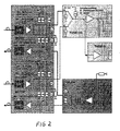
- FIG. 2 shows a circuit with which the control signal can be generated.
- the MOTR transceiver signals whether optical power is present at its input; if so, the first switch is closed, so that a positive DC voltage potential is present at the two symmetrical outputs - in addition to the RF signal.
- the amplifier TVB can thus decide by measuring the voltages V 3 and V 4 which input A or B carries a valid RF signal. As a rule, it switches to input A, only in the event that A does not carry an RF signal (V 3 ⁇ 3V) and B carries an RF signal (V 4 ⁇ 3V), is switched to input B.
- the TVB amplifier signals the input to which it is connected with a 10 k ⁇ resistor against + 5V.
- the transceiver MOTR can thus decide by measuring the potential at the output (V 1 and V 2 ) whether the amplifier TVB is connected to one of its two outputs and therefore has to switch on its output amplifier.
- the amplifier modules shown are able to switch the redundancy circuit To accomplish DC signals on the coaxial cables.
Landscapes
- Engineering & Computer Science (AREA)
- Multimedia (AREA)
- Signal Processing (AREA)
- Two-Way Televisions, Distribution Of Moving Picture Or The Like (AREA)
- Details Of Television Systems (AREA)
- Selective Calling Equipment (AREA)
- Cable Transmission Systems, Equalization Of Radio And Reduction Of Echo (AREA)
Abstract
Description
Claims (6)
- Gestell, insbesondere für Kabelfernsehen, mit einer Vielzahl von Baugruppenn, deren Ein- und Ausgänge mit Kabeln zur Übertragung von Hochfrequenzsignalen und von Steuersignalen verbunden sind, dadurch gekennzeichnet, daß die Baugruppen (2) über die gemeinsamen Ein- und Ausgänge durch Koaxialkabel (3) verbunden sind, die sowohl Hochfrequenzsignale wie auch codierte Steuersignale führen.
- Gestell nach Anspruch 1, dadurch gekennzeichnet, daß eine Gleichspannung für die Steuersignale verwendet wird und daß die Steuersignale mittels Frequenzmultiplex den Hochfrequenzsignalen zugefügt werden.
- Gestell nach Anspruch 1 oder 2, dadurch gekennzeichnet, daß die Steuersignale durch unterschiedliche Gleichspannungspegel codiert sind.
- Gestell nach einem der Ansprüche 1 bis 3, dadurch gekennzeichnet, daß die Baugruppen (2) Schaltungen zur Codierung der Steuersignale enthalten.
- Gestell nach einem der Ansprüche 1 bis 4, dadurch gekennzeichnet, daß die Baugruppen (2) Schaltungen enthalten, welche die Hochfrequenzsignale und die Steuersignale zusammenfassen, so daß diese über gemeinsame Ein- und Ausgänge geführt werden.
- Gestell nach einem der Ansprüche 1 bis 5, dadurch gekennzeichnet, daß die Steuersignale über den Innenleiter des Koaxialkabels (3) geleitet werden.
Applications Claiming Priority (2)
| Application Number | Priority Date | Filing Date | Title |
|---|---|---|---|
| DE10056056 | 2000-11-11 | ||
| DE10056056A DE10056056A1 (de) | 2000-11-11 | 2000-11-11 | Gestell, insbesondere für Kabelfernsehen |
Publications (2)
| Publication Number | Publication Date |
|---|---|
| EP1206140A2 true EP1206140A2 (de) | 2002-05-15 |
| EP1206140A3 EP1206140A3 (de) | 2002-10-09 |
Family
ID=7663036
Family Applications (1)
| Application Number | Title | Priority Date | Filing Date |
|---|---|---|---|
| EP01440375A Withdrawn EP1206140A3 (de) | 2000-11-11 | 2001-11-08 | Gestell, insbesondere für Kabelfernsehen |
Country Status (3)
| Country | Link |
|---|---|
| US (1) | US7063564B2 (de) |
| EP (1) | EP1206140A3 (de) |
| DE (1) | DE10056056A1 (de) |
Families Citing this family (1)
| Publication number | Priority date | Publication date | Assignee | Title |
|---|---|---|---|---|
| US7412208B1 (en) * | 2002-03-11 | 2008-08-12 | Agilent Technologies, Inc. | Transmission system for transmitting RF signals, power and control signals via RF coaxial cables |
Family Cites Families (7)
| Publication number | Priority date | Publication date | Assignee | Title |
|---|---|---|---|---|
| GB2165412B (en) * | 1984-10-05 | 1988-08-10 | Stc Plc | Improvements in optical transmission systems |
| US5136411A (en) * | 1987-12-11 | 1992-08-04 | General Instrument Corporation | Dynamically responsive CATV system with shared fiber optic link |
| US5282193A (en) * | 1990-11-24 | 1994-01-25 | Fujitsu Limited | Maintenance signal transmission system |
| JPH0946110A (ja) * | 1995-07-26 | 1997-02-14 | Sony Corp | ダイバシティアンテナ装置及び通信機 |
| US6144561A (en) * | 1998-12-01 | 2000-11-07 | Scientific-Atlanta, Inc. | Connectorization panel assembly for circuit board housing rack |
| US6449768B1 (en) * | 1999-04-28 | 2002-09-10 | Adc Telecommunications, Inc. | Split linked A/B switch apparatus |
| JP2002217805A (ja) * | 2001-01-23 | 2002-08-02 | Nec Saitama Ltd | 携帯電話機 |
-
2000
- 2000-11-11 DE DE10056056A patent/DE10056056A1/de not_active Withdrawn
-
2001
- 2001-11-08 EP EP01440375A patent/EP1206140A3/de not_active Withdrawn
- 2001-11-13 US US09/986,866 patent/US7063564B2/en not_active Expired - Fee Related
Also Published As
| Publication number | Publication date |
|---|---|
| EP1206140A3 (de) | 2002-10-09 |
| US7063564B2 (en) | 2006-06-20 |
| US20020095690A1 (en) | 2002-07-18 |
| DE10056056A1 (de) | 2002-05-16 |
Similar Documents
| Publication | Publication Date | Title |
|---|---|---|
| DE69028377T2 (de) | Gerät zur Übertragung zwischen elektronischen Systemen | |
| DE102010027283A1 (de) | Verkehrsmittel und Verfahren zur Datenübertragung in einem Verkehrsmittel | |
| DE69018475T2 (de) | Vorrichtung zum schalten von hf-signalen. | |
| WO2000070764A1 (de) | Kompakte busschnittstelle mit integrierter potentialtrennung | |
| DE2809633A1 (de) | Gesteuerter erzeuger von perioden- signalbildern | |
| DE2903327A1 (de) | Schaltungsanordnung zur uebertragung von gleichstromsignalen zwischen galvanisch getrennten signalleitungen | |
| DE69630468T2 (de) | Verteilungssystem für breitbandsignale | |
| EP0977126A2 (de) | Schnittstelle für I2C-Bus | |
| EP1206140A2 (de) | Gestell, insbesondere für Kabelfernsehen | |
| DE102011088826A1 (de) | Netzwerkvorrichtung für ein kabelgebundenes Datennetz sowie Brandmeldesystem mit der Netzwerkvorrichtung | |
| DE3715594C2 (de) | Anordnung zum Anschluß von Ausgangs- und Eingangsstufen einer Sende/Empfangseinrichtung | |
| DE3543229C1 (de) | Hausverteilnetz fuer Einzel- und Gemeinschafts-Antennenanlagen | |
| EP0419711B1 (de) | Schnittstellenbaustein zur Ankopplung modulierter Signale | |
| EP2161920B1 (de) | Körpermontierbares Kameratragesystem mit einem multifunktionalen Verbund elektrischer Komponenten | |
| DE69509802T2 (de) | Schaltung zur isolierung von schnittstellen für differentielle signale | |
| WO2023148207A1 (de) | Elektrooptischer mischer | |
| EP0416679A1 (de) | Datenübertragungsanordnung mit einer differentiell betriebenen Datenübertragungsstrecke | |
| EP0038509A1 (de) | Logikschaltung zum Vermeiden eines Verriegelungszustandes zwischen voneinander entfernten Datenbussen | |
| DE3503364A1 (de) | Datenverteilnetz mit aktiven optischen sternkopplern | |
| DE60018847T2 (de) | Anschlussvorrichtung für elektronische Einheiten oder Module | |
| EP0149023A1 (de) | Endstufenanordnung | |
| DE4202340C1 (en) | Signal regenerating unit for transmission path - includes converting circuit supplying power to signal processor from received signal to be regenerated | |
| WO1998013976A1 (de) | Übertrager-leitungskopplung | |
| DE102016011257A1 (de) | Bus- und Kommunikationssystem zur gleichstromfreien Signalübertragung auf einem gemeinsamen Medium mit Terminierung | |
| EP0101610B1 (de) | Aktive Gabelschaltung mit geringer Verlustleistung |
Legal Events
| Date | Code | Title | Description |
|---|---|---|---|
| PUAI | Public reference made under article 153(3) epc to a published international application that has entered the european phase |
Free format text: ORIGINAL CODE: 0009012 |
|
| AK | Designated contracting states |
Kind code of ref document: A2 Designated state(s): AT BE CH CY DE DK ES FI FR GB GR IE IT LI LU MC NL PT SE TR |
|
| AX | Request for extension of the european patent |
Free format text: AL;LT;LV;MK;RO;SI |
|
| PUAL | Search report despatched |
Free format text: ORIGINAL CODE: 0009013 |
|
| AK | Designated contracting states |
Kind code of ref document: A3 Designated state(s): AT BE CH CY DE DK ES FI FR GB GR IE IT LI LU MC NL PT SE TR |
|
| AX | Request for extension of the european patent |
Free format text: AL;LT;LV;MK;RO;SI |
|
| RIC1 | Information provided on ipc code assigned before grant |
Free format text: 7H 04N 7/173 A, 7H 04N 7/10 B, 7H 04N 7/22 B, 7H 05K 7/14 B |
|
| 17P | Request for examination filed |
Effective date: 20021206 |
|
| AKX | Designation fees paid |
Designated state(s): AT BE CH CY DE DK ES FI FR GB GR IE IT LI LU MC NL PT SE TR |
|
| RAP1 | Party data changed (applicant data changed or rights of an application transferred) |
Owner name: FUBA COMMUNICATIONS SYSTEMS GMBH Owner name: ALCATEL LUCENT |
|
| 17Q | First examination report despatched |
Effective date: 20080218 |
|
| STAA | Information on the status of an ep patent application or granted ep patent |
Free format text: STATUS: THE APPLICATION IS DEEMED TO BE WITHDRAWN |
|
| 18D | Application deemed to be withdrawn |
Effective date: 20080829 |