EP1206049A1 - Procédé pour l'acquisition d'une fonction de gain d'émission - Google Patents
Procédé pour l'acquisition d'une fonction de gain d'émission Download PDFInfo
- Publication number
- EP1206049A1 EP1206049A1 EP01402662A EP01402662A EP1206049A1 EP 1206049 A1 EP1206049 A1 EP 1206049A1 EP 01402662 A EP01402662 A EP 01402662A EP 01402662 A EP01402662 A EP 01402662A EP 1206049 A1 EP1206049 A1 EP 1206049A1
- Authority
- EP
- European Patent Office
- Prior art keywords
- vector
- transmission
- downlink
- channel
- array
- Prior art date
- Legal status (The legal status is an assumption and is not a legal conclusion. Google has not performed a legal analysis and makes no representation as to the accuracy of the status listed.)
- Granted
Links
Images


Classifications
-
- H—ELECTRICITY
- H04—ELECTRIC COMMUNICATION TECHNIQUE
- H04B—TRANSMISSION
- H04B7/00—Radio transmission systems, i.e. using radiation field
- H04B7/02—Diversity systems; Multi-antenna system, i.e. transmission or reception using multiple antennas
- H04B7/04—Diversity systems; Multi-antenna system, i.e. transmission or reception using multiple antennas using two or more spaced independent antennas
- H04B7/06—Diversity systems; Multi-antenna system, i.e. transmission or reception using multiple antennas using two or more spaced independent antennas at the transmitting station
- H04B7/0613—Diversity systems; Multi-antenna system, i.e. transmission or reception using multiple antennas using two or more spaced independent antennas at the transmitting station using simultaneous transmission
- H04B7/0615—Diversity systems; Multi-antenna system, i.e. transmission or reception using multiple antennas using two or more spaced independent antennas at the transmitting station using simultaneous transmission of weighted versions of same signal
- H04B7/0617—Diversity systems; Multi-antenna system, i.e. transmission or reception using multiple antennas using two or more spaced independent antennas at the transmitting station using simultaneous transmission of weighted versions of same signal for beam forming
Definitions
- the present invention concerns in general terms a method for obtaining a transmission gain function. More particularly, the present invention relates to a method for obtaining an antenna gain in transmission mode for a base station in a mobile telecommunication system. It makes it possible to obtain an antenna gain function in transmission mode from an antenna gain function in reception mode.
- each uses an array of antennae, generally linear and uniform (that is to say with a constant pitch) and a signal weighting module. More precisely, if it is wished to form a beam in reception mode, the signals received by the different antennae are weighted by a set of complex coefficients before being added. Conversely, if it is wished to form a beam in transmission mode, the signal to be transmitted is weighted by a set of complex coefficients and the signals thus obtained are transmitted by the different antennae.
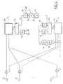
- Fig. 1 illustrates a known device for obtaining an antenna gain in transmission and reception.
- the device comprises an array of antennae (10 0 ),(10 1 ),...,(10 N-1 ), a transmission weighting module (11) and a reception weighting module (15).
- ⁇ i is the angle between a reference axis and the normal to the antenna of index i
- R the radius of curvature of the array
- ⁇ is the angular difference between two consecutive antennae in the array.
- the complex gain (or the complex gain function) in transmission can be written: with the same conventions as those adopted above and where ed ⁇ represents the vector x corresponding to a plane wave transmitted in the direction ⁇ .
- the weighting vectors in reception and transmission mode will be called respectively b u and b d .
- the array of antennae of a base station receives signals transmitted by a plurality of mobile terminals.
- the signals transmitted by the different mobile terminals are separated by means of the use of orthogonal codes on transmission and filters adapted to these codes on reception. In practice, however, the separation of the different signals received is not perfect.
- the criterion to be maximised is then the ratio of signal to noise plus interference, the latter being due to the signals transmitted by the other mobile terminals.
- the downlink between a base station and a given mobile terminal is disturbed not only by the background noise but by the interference due to the signals transmitted by the said base station to other mobile terminals.
- optimise the weighting vector in reception mode, b u by estimating the uplink channel and the density of interference at the base station, it is quite different with regard to the optimisation of the weighting vector in transmission mode, b d .
- the aim of the invention is to propose a method of determining the transmission weighting vector, b d , optimising the ratio of signal to noise plus interference on the downlink and requiring the transmission only of a small quantity of information on the uplinks.
- the invention is defined by a method of obtaining a gain function on transmission by means of an array of antennae, a signal to be transmitted by the network being weighted by a vector ( b d ) of N complex coefficients, referred to as a transmission weighting vector, N being the number of antennae in the array, the array transmitting to a telecommunication terminal on a transmission channel, referred to as the downlink, a downlink transmission signal (S d ), and the said terminal transmitting to the said network on a transmission channel, referred to as the uplink channel, an uplink transmission signal (S u ), the said downlink channel being interfered with by an isotropic noise (N') and/or a directional noise, referred to as the downlink interference (I d ), the said transmission weighting vector ( b d ) being determined by means of a matrix product from a noise power matrix ( D d ) which is a function of the power of the said isotropic noise and/or the power of the said said transmission weighting
- the said downlink channel vector ( C d ) is obtained from variations in the transfer function of the uplink channel.
- the said downlink channel vector ( C d ) is obtained for example from variations ( ⁇ C u ) in a vector ( C u ), referred to as the uplink channel vector, representing an angular sampling of the transfer function of the uplink channel in the said M directions.
- the variations ( ⁇ C d ) in the downlink channel vector can be obtained from variations ( ⁇ C u ) in the uplink channel.
- the said downlink channel vector ( C d ) is then obtained by integration of the said variations ( ⁇ C d ) in the said downlink channel vector and an initial value ( C d (0)) transmitted by the said terminal.
- the array transmitting on a plurality of downlink channels a plurality of transmission signals to a plurality of telecommunication terminals and receiving from them a plurality of transmission signals transmitted on a plurality of uplink channels, each downlink channel j relating to a terminal j of the said plurality being associated with a transmission weighting vector b d ( j ), the second noise matrix relating to the downlink channel j is a diagonal matrix of size MxM and components ⁇ 2 dk ( j )+ ⁇ d ( j ).
- N ' 0 / I d (j) where ⁇ 2 / dk ( j ) is the power of the downlink interference for the downlink channel j in the direction k , ⁇ d (j) is a coefficient characterising the power transfer on the downlink channel j, N' 0 is the power of the second isotropic noise, and I d is the total power of the downlink interference.
- the coefficient ⁇ d ( j ) is transmitted to the array by the terminal j on the associated uplink channel.
- the coefficient ⁇ d ( j ) is estimated by the base station from a coefficient ( ⁇ ) characterising the power transfer in the uplink direction.
- the downlink interference power in the direction k can be estimated according to the power of the signals ( S d (j')) transmitted on the downlink channels j' distinct from j, a coefficient ⁇ d (j) characterising the orthogonality of the downlink channel j, components ( g dk (j')) of the gain vectors ( G d ( j' )) relating to the said distinct downlink channels j', the gain vectors consisting of an angular sampling in the said M directions of the transmission gain functions obtained for the said distinct downlink channels j' .
- the said coefficient ⁇ d (j) can be estimated from a coefficient characterising the orthogonality of the uplink channel j .
- the invention is also defined by a device adapted to implement the method disclosed above.
- a first general idea at the basis of the invention is to sample the transmission and reception gain functions in order to construct transmission and reception gain vectors.
- optimum weighting vectors in terms of ratio of signal to noise plus interference, can then be obtained from transmission and reception gain vectors according to matrix equations.
- a second general idea at the basis of the invention is to obtain a transmission weighting vector, optimum in terms of ratio of signal to noise plus interference obtained, according to the reception gain weighting vector assumed itself to be optimum.
- a third general idea at the basis of the invention is to estimate the downlink channel from variations in the uplink channel.
- weighting vectors can be obtained from a series of samples of the corresponding gain function.
- G( ⁇ ) be the antenna gain function obtained by means of a weighting vector b .
- the image of C N by h f s is a vector sub-space of C M with a dimension at most equal to N , which will be denoted Im f . If a base of C N is chosen, for example the canonical base, and a base of C M , it is possible to express the linear application h f s by a matrix H f of size MxN which is at most of rank N.
- H + / f (H *T / f.H f ) -1 .
- H *T / f is the pseudo-inverse matrix of the matrix H f with H *T / f a conjugate transpose of the matrix H f .
- the vectors e k are the weighting vectors of the array making it possible to form beams in the directions ⁇ k .
- H' f H f .T -1
- This equation makes it possible in particular to obtain, at a second working frequency, a sampled gain diagram which is as close as possible to the one, referred to as the reference, obtained at a first working frequency.
- Equation (10) applies advantageously to the array of antennae of a base station in a mobile telecommunication system operating in FDD (Frequency Division Duplex) mode.
- a frequency f d is used on the downlinks and a frequency f u distinct from f d is used on the uplinks.
- Equation (11) makes it possible, as has been seen, to obtain, at the transmission frequency f u , a sampled gain diagram which is as close as possible to a reference diagram obtained at the reception frequency f d .
- the interference profile that is to say the angular distribution of the power of the interference, is not necessarily the same on the downlink channel as on the uplink channel. This is because the directions of the interfering sources are not necessarily identical in transmission and reception. Consequently, though the reception gain diagram is optimum for a reception interference profile, it will not necessarily be so for a transmission interference profile. As will be shown later, if the transmission and reception interference profiles differ, equation (11) must be modified in order to take account of this difference.
- Fig. 2 depicts the assembly consisting of the uplink channel (20), the array of antennae (22) and the reception weighting module (23).
- the effect of the noise has been represented by the addition (21) of a directional noise I u due to the interfering signals, and at (24) an isotropic centred white Gaussian background noise N.
- the signal R u received by the base station can be written: where G u is the reception gain vector and S u is the signal transmitted by the mobile terminal.
- Fig. 3 depicts the assembly consisting of the downlink channel (30), the array of antennae (32) and the transmission weighting module (33).
- the effect of the noise has been represented by the addition at (31) of a directional noise I d due to the interfering signals and at (34) by a centred isotropic white Gaussian background noise N'.
- the matrix D u can be estimated at the base station from a measurement of the noise power and the interference in the directions ⁇ k , for example during a period of silence of the mobile terminal.
- the matrix D d cannot be estimated as simply.
- ⁇ d can be estimated by the mobile terminal and transmitted over the uplink channel to the base station. Since ⁇ d changes only slowly over time, the quantity of information to be transmitted relating to this parameter will be small.
- the value of ⁇ can then be estimated directly by the base station, for example at the power control loop.
- the interference power attributable to the mobile terminals TS j in the direction ⁇ k can be written: where the indices between parentheses have been added so as to distinguish the quantities relating to the different downlink channels (that is to say intended for the different mobile terminals) and where:
- the coefficient of orthogonality of the downlink channel, ⁇ d (j 0 ) is little different from that of the uplink channel, ⁇ u (j 0 )
- the above three quantities are available at the base station without a return of information by the mobile terminal being necessary.
- the power transfer coefficient, ⁇ d (j 0 ) is transmitted to the base station on the uplink channel from TS j0 or directly estimated by the latter. It is therefore possible to obtain the matrix D d for a slight additional cost in terms of transport resources.
- the method according to the present invention proposes to calculate the optimum vector b d from equation (21) and an estimation of the downlink channel, that is to say of the vector C d .
- the vector C u has non-zero components in the directions where the uplink channel has propagation paths.
- c uk ⁇ uk .exp -j (2 ⁇ f u .L uk / c+ ⁇ uk )
- L uk is the length of the path concerned
- ⁇ uk the coefficient of attenuation of the signal propagating along the said path
- ⁇ uk is the polarisation of the incident signal
- c uk 0 otherwise.
- the components of the vector C u , c uk can, for example, be determined, in a manner known per se, by means of pilot symbols transmitted by the mobile terminal.
- an estimation will be carried out of the coefficients of attenuation ⁇ uk and of the directions of arrival of the paths conjointly, as described in the French patent application N° 00 11160 filed on 29.8.2000 in the name of the applicant.
- the vector C u relating to a given uplink channel, is first of all differentiated, or in other words the variation in the vector C u during the interval of time ⁇ t separating two consecutive estimations is evaluated.
- the initialisation of the calculation is effected by means of a vector C d (0) of components c dk (0). These components are estimated by the mobile terminal by means of pilot symbols transmitted by the base station in the different directions ⁇ k . The components are estimated periodically by the mobile terminal and transmitted, via the uplink channel, to the base station. At each new estimation, the integration calculation is reinitialised with the new components transmitted.
- Fig. 4 illustrates an example of a device according to one embodiment of the invention. For reasons of simplicity, the processing of only one communication with a mobile terminal has been shown.
- the device installed at the base station, comprises an array of antennae (40 0 ),(40 1 ),..(40 N-1 ) coupled by means of duplexers to a first weighting module (41 1 ) on reception, weighting the signals received by the different antennae by means of a first weighting vector, b u , and a second weighting module (41 2 ) on transmission, weighting a signal to be transmitted by a second weighting vector, b d .
- the device When the device manages several communications with a plurality of mobile terminals, other weighting modules identical to the modules (41 1 ), (41 2 ) must be provided in parallel with the latter.
- the signals received by the different antennae are demultiplexed according to the different users (that is to say the different mobile terminals). If the telecommunication system is a system of the DS-CDMA type, the demultiplexing will be carried out for example by means of a battery of filters adapted to the signatures of the different users, denoted (49).
- the M signals are transmitted to a module (44 1 ) for evaluating the noise power matrix D u and to a module (43) for estimating the (uplink) channel C u .
- the vector C u is estimated by means of pilot symbols transmitted by the mobile terminal.
- the noise power matrix D u is estimated during periods of silence of the mobile terminal.
- the matrix D u and the vector C u are supplied to a module (42 1 ) which calculates the vector b u according to equation (16) and transmits it to the weighting module (41 1 ).
- the vector C u is then differentiated by a differentiating filter (46).
- the resulting vector ⁇ C u is multiplied at (47) by the matrix M in order to give the vector ⁇ d .
- This vector then servers for integrating the vector C d in the integrator (48).
- This integrator is regularly initialised by the estimations of the downlink channel transmitted by the mobile terminal, denoted C d (0).
- the vector C d is transmitted to the matrix-type calculation module (42 2 ).
- This module also receives from (44 2 ) the noise power matrix D d .
- This matrix is evaluated in (44 2 ) by means of equation (23). To do this, the module (44 2 ) receives an estimation of the coupling coefficient, ⁇ d or ⁇ according to circumstances, of the interference powers ⁇ 2 / dk in the directions ⁇ k as well as the total power I d .
- the values ⁇ 2 / dk are advantageously calculated from equation (24) using the values of the transmission signals, S d (j) , j ⁇ j 0 , intended for the mobile terminals other than the one in question ( j 0 ) and the gain vectors, G d ( j ), j ⁇ j 0 , which are associated with them.
- the module (42 2 ) effects the calculation of the vector b d in accordance with equation (21) and transmits it to the weighting module (41 2 ).
Applications Claiming Priority (2)
| Application Number | Priority Date | Filing Date | Title |
|---|---|---|---|
| FR0014362 | 2000-10-31 | ||
| FR0014362A FR2816141B1 (fr) | 2000-10-31 | 2000-10-31 | Procede d'obtention de fonction de gain a l'emission |
Publications (2)
| Publication Number | Publication Date |
|---|---|
| EP1206049A1 true EP1206049A1 (fr) | 2002-05-15 |
| EP1206049B1 EP1206049B1 (fr) | 2003-07-16 |
Family
ID=8856221
Family Applications (1)
| Application Number | Title | Priority Date | Filing Date |
|---|---|---|---|
| EP01402662A Expired - Lifetime EP1206049B1 (fr) | 2000-10-31 | 2001-10-15 | Procédé pour l'acquisition d'une fonction de gain d'émission |
Country Status (7)
| Country | Link |
|---|---|
| US (1) | US6952459B2 (fr) |
| EP (1) | EP1206049B1 (fr) |
| JP (1) | JP4070074B2 (fr) |
| CN (1) | CN1197403C (fr) |
| AT (1) | ATE245321T1 (fr) |
| DE (1) | DE60100467D1 (fr) |
| FR (1) | FR2816141B1 (fr) |
Cited By (1)
| Publication number | Priority date | Publication date | Assignee | Title |
|---|---|---|---|---|
| WO2009152852A1 (fr) * | 2008-06-18 | 2009-12-23 | Telefonaktiebolaget L M Ericsson (Publ) | Réduction de brouillage intercellulaire |
Families Citing this family (10)
| Publication number | Priority date | Publication date | Assignee | Title |
|---|---|---|---|---|
| US7133461B2 (en) * | 2001-12-14 | 2006-11-07 | Motorola, Inc. | Stream transmission method and device |
| US8185075B2 (en) | 2003-03-17 | 2012-05-22 | Broadcom Corporation | System and method for channel bonding in multiple antenna communication systems |
| US7391832B2 (en) * | 2003-03-17 | 2008-06-24 | Broadcom Corporation | System and method for channel bonding in multiple antenna communication systems |
| US7502432B2 (en) * | 2003-07-09 | 2009-03-10 | Broadcom Corporation | Weight generation method for multi-antenna communication systems utilizing RF-based and baseband signal weighting and combining based upon minimum bit error rate |
| US7522919B2 (en) * | 2003-07-14 | 2009-04-21 | Telefonaktiebolaget Lm Ericsson (Publ) | Enhancements to periodic silences in wireless communication systems |
| EP1656757A4 (fr) * | 2003-07-21 | 2011-12-28 | Broadcom Corp | Procede de generation de poids destine a des systemes de communication a antennes multiples utilisant la ponderation et la combinaison de signaux bases rf et a bande de base basee sur un taux d'erreur binaire minimum |
| GB2427989B (en) * | 2004-03-09 | 2007-08-08 | Alexander Vasilievich Garmonov | Method and apparatus of data transmission |
| US20070058584A1 (en) * | 2005-09-12 | 2007-03-15 | Ilan Sutskover | Techniques to transmit and duplex with channel knowledge at a base station |
| US8634766B2 (en) | 2010-02-16 | 2014-01-21 | Andrew Llc | Gain measurement and monitoring for wireless communication systems |
| EP3588851B1 (fr) * | 2018-06-28 | 2023-02-01 | Mitsubishi Electric R&D Centre Europe B.V. | Procédé de configuration de noeud de réseau d'accès et appareil permettant sa mise en oeuvre |
Citations (2)
| Publication number | Priority date | Publication date | Assignee | Title |
|---|---|---|---|---|
| EP0999658A2 (fr) * | 1998-11-06 | 2000-05-10 | Lucent Technologies Inc. | Diversité d'espace et temps pour des systèmes sans fil |
| EP1003298A1 (fr) * | 1998-06-24 | 2000-05-24 | Matsushita Electric Industrial Co., Ltd. | Dispositif et procede de transmission a directivite adaptative |
Family Cites Families (8)
| Publication number | Priority date | Publication date | Assignee | Title |
|---|---|---|---|---|
| US6101399A (en) * | 1995-02-22 | 2000-08-08 | The Board Of Trustees Of The Leland Stanford Jr. University | Adaptive beam forming for transmitter operation in a wireless communication system |
| CA2302289C (fr) * | 1996-08-29 | 2005-11-08 | Gregory G. Raleigh | Traitement spatio-temporel pour telecommunications |
| US6463295B1 (en) * | 1996-10-11 | 2002-10-08 | Arraycomm, Inc. | Power control with signal quality estimation for smart antenna communication systems |
| US6615024B1 (en) * | 1998-05-01 | 2003-09-02 | Arraycomm, Inc. | Method and apparatus for determining signatures for calibrating a communication station having an antenna array |
| SG80071A1 (en) * | 1999-09-24 | 2001-04-17 | Univ Singapore | Downlink beamforming method |
| KR100689398B1 (ko) * | 1999-10-09 | 2007-03-08 | 삼성전자주식회사 | 이동통신시스템에서 폐루프 송신 안테나 다이버시티 장치 및 방법 |
| FR2813465B1 (fr) | 2000-08-29 | 2005-04-08 | Mitsubishi Electric Inf Tech | Methode d'estimation conjointe de canal et de direction d'arrivee |
| FR2816140B1 (fr) * | 2000-10-31 | 2002-12-06 | Mitsubishi Electric Inf Tech | Procede d'obtention de fonction de gain a l'emission |
-
2000
- 2000-10-31 FR FR0014362A patent/FR2816141B1/fr not_active Expired - Fee Related
-
2001
- 2001-10-09 JP JP2001311234A patent/JP4070074B2/ja not_active Expired - Fee Related
- 2001-10-15 AT AT01402662T patent/ATE245321T1/de not_active IP Right Cessation
- 2001-10-15 EP EP01402662A patent/EP1206049B1/fr not_active Expired - Lifetime
- 2001-10-15 DE DE60100467T patent/DE60100467D1/de not_active Expired - Lifetime
- 2001-10-19 US US09/981,980 patent/US6952459B2/en not_active Expired - Fee Related
- 2001-10-31 CN CN01142733.7A patent/CN1197403C/zh not_active Expired - Fee Related
Patent Citations (2)
| Publication number | Priority date | Publication date | Assignee | Title |
|---|---|---|---|---|
| EP1003298A1 (fr) * | 1998-06-24 | 2000-05-24 | Matsushita Electric Industrial Co., Ltd. | Dispositif et procede de transmission a directivite adaptative |
| EP0999658A2 (fr) * | 1998-11-06 | 2000-05-10 | Lucent Technologies Inc. | Diversité d'espace et temps pour des systèmes sans fil |
Non-Patent Citations (2)
| Title |
|---|
| ASTE T ET AL: "DOWNLINK BEAMFORMING FOR CELLULAR MOBILE COMMUNICATIONS (GSM SYSTEM)", ANNALES DES TELECOMMUNICATIONS - ANNALS OF TELECOMMUNICATIONS,PRESSES POLYTECHNIQUES ET UNIVERSITAIRES ROMANDES, LAUSANNE,CH, vol. 53, no. 11/12, November 1998 (1998-11-01), pages 435 - 448, XP000804147, ISSN: 0003-4347 * |
| GOLDBERG J ET AL: "DOWNLINK BEAMFORMING FOR CELLULAR MOBILE COMMUNICATIONS", PHOENIX, MAY 4 - 7, 1997,NEW YORK, IEEE,US, vol. CONF. 47, 4 May 1997 (1997-05-04), pages 632 - 636, XP000736684, ISBN: 0-7803-3660-7 * |
Cited By (2)
| Publication number | Priority date | Publication date | Assignee | Title |
|---|---|---|---|---|
| WO2009152852A1 (fr) * | 2008-06-18 | 2009-12-23 | Telefonaktiebolaget L M Ericsson (Publ) | Réduction de brouillage intercellulaire |
| US8838034B2 (en) | 2008-06-18 | 2014-09-16 | Telefonaktiebolaget L M Ericsson (Publ) | Intercell interference reduction |
Also Published As
| Publication number | Publication date |
|---|---|
| JP4070074B2 (ja) | 2008-04-02 |
| FR2816141B1 (fr) | 2002-12-06 |
| JP2002198877A (ja) | 2002-07-12 |
| DE60100467D1 (de) | 2003-08-21 |
| US20020105472A1 (en) | 2002-08-08 |
| CN1351456A (zh) | 2002-05-29 |
| ATE245321T1 (de) | 2003-08-15 |
| EP1206049B1 (fr) | 2003-07-16 |
| US6952459B2 (en) | 2005-10-04 |
| CN1197403C (zh) | 2005-04-13 |
| FR2816141A1 (fr) | 2002-05-03 |
Similar Documents
| Publication | Publication Date | Title |
|---|---|---|
| Mishra et al. | Optimal channel estimation for reciprocity-based backscattering with a full-duplex MIMO reader | |
| CN111313951B (zh) | 基于非理想csi的irs辅助安全通信无线传输方法 | |
| EP1206049B1 (fr) | Procédé pour l'acquisition d'une fonction de gain d'émission | |
| KR101268691B1 (ko) | 스마트 안테나 시스템에서 빔 성형에 의해 데이터를수신하는 장치 및 방법 | |
| US6687188B2 (en) | Underwater telemetry apparatus and method | |
| CN108650007B (zh) | 一种基于空频自适应滤波的高可靠信道均衡方法 | |
| JP2008541639A (ja) | 多入力多出力通信システム | |
| US6836507B1 (en) | Symbol synchronizer for software defined communications system signal combiner | |
| US10879966B2 (en) | MIMO bolt-on device, MIMO channel emulator, and MIMO channel emulation method | |
| CN114095318A (zh) | 智能超表面辅助的混合构型毫米波通信系统信道估计方法 | |
| CN101569055A (zh) | 天线系统和用于操作天线系统的方法 | |
| CN114900400B (zh) | 一种基于智能反射面辅助物联网的联合稀疏信道估计方法 | |
| Shaddad et al. | Channel estimation for intelligent reflecting surface in 6G wireless network via deep learning technique | |
| Zhang et al. | RIS-aided 6G communication system with accurate traceable user mobility | |
| EP1204220B1 (fr) | Procédé pour l'acquisition d'une fonction de gain d'émission | |
| EP1198150B1 (fr) | Procédé d'estimation d'un canal descendant | |
| Rivera et al. | Optimization of quantized phase shifts for reconfigurable smart surfaces assisted communications | |
| Mahfoudi et al. | Joint range extension and localization for low‐power wide‐area network | |
| US8014981B2 (en) | Angular-domain channel model and channel estimation | |
| Fens et al. | Channel characterization using radar for transmission of communication signals | |
| CN113556168B (zh) | 一种针对多智能反射面的码分多址传输方法 | |
| Ueng et al. | Re-configurable Intelligent Surfaces Assisted Simultaneous Wireless Information and Power Transfer | |
| CN115189725B (zh) | 一种大规模mimo散射通信系统下的信道估计方法 | |
| Karadimas et al. | Channel Modeling for 6G Programmable Wireless Environment | |
| Kang et al. | Joint channel training and passive beamforming design for intelligent reflecting surface-aided LoRa systems |
Legal Events
| Date | Code | Title | Description |
|---|---|---|---|
| PUAI | Public reference made under article 153(3) epc to a published international application that has entered the european phase |
Free format text: ORIGINAL CODE: 0009012 |
|
| AK | Designated contracting states |
Kind code of ref document: A1 Designated state(s): AT BE CH CY DE DK ES FI FR GB GR IE IT LI LU MC NL PT SE TR |
|
| AX | Request for extension of the european patent |
Free format text: AL;LT;LV;MK;RO;SI |
|
| 17P | Request for examination filed |
Effective date: 20020912 |
|
| GRAH | Despatch of communication of intention to grant a patent |
Free format text: ORIGINAL CODE: EPIDOS IGRA |
|
| AKX | Designation fees paid |
Designated state(s): AT BE CH CY DE DK ES FI FR GB GR IE IT LI LU MC NL PT SE TR |
|
| RAP1 | Party data changed (applicant data changed or rights of an application transferred) |
Owner name: MITSUBISHI ELECTRIC INFORMATION TECHNOLOGY CENTRE |
|
| GRAH | Despatch of communication of intention to grant a patent |
Free format text: ORIGINAL CODE: EPIDOS IGRA |
|
| GRAA | (expected) grant |
Free format text: ORIGINAL CODE: 0009210 |
|
| AK | Designated contracting states |
Designated state(s): AT BE CH CY DE DK ES FI FR GB GR IE IT LI LU MC NL PT SE TR |
|
| PG25 | Lapsed in a contracting state [announced via postgrant information from national office to epo] |
Ref country code: IT Free format text: LAPSE BECAUSE OF FAILURE TO SUBMIT A TRANSLATION OF THE DESCRIPTION OR TO PAY THE FEE WITHIN THE PRESCRIBED TIME-LIMIT;WARNING: LAPSES OF ITALIAN PATENTS WITH EFFECTIVE DATE BEFORE 2007 MAY HAVE OCCURRED AT ANY TIME BEFORE 2007. THE CORRECT EFFECTIVE DATE MAY BE DIFFERENT FROM THE ONE RECORDED. Effective date: 20030716 Ref country code: NL Free format text: LAPSE BECAUSE OF FAILURE TO SUBMIT A TRANSLATION OF THE DESCRIPTION OR TO PAY THE FEE WITHIN THE PRESCRIBED TIME-LIMIT Effective date: 20030716 Ref country code: CH Free format text: LAPSE BECAUSE OF FAILURE TO SUBMIT A TRANSLATION OF THE DESCRIPTION OR TO PAY THE FEE WITHIN THE PRESCRIBED TIME-LIMIT Effective date: 20030716 Ref country code: BE Free format text: LAPSE BECAUSE OF FAILURE TO SUBMIT A TRANSLATION OF THE DESCRIPTION OR TO PAY THE FEE WITHIN THE PRESCRIBED TIME-LIMIT Effective date: 20030716 Ref country code: AT Free format text: LAPSE BECAUSE OF FAILURE TO SUBMIT A TRANSLATION OF THE DESCRIPTION OR TO PAY THE FEE WITHIN THE PRESCRIBED TIME-LIMIT Effective date: 20030716 Ref country code: TR Free format text: LAPSE BECAUSE OF FAILURE TO SUBMIT A TRANSLATION OF THE DESCRIPTION OR TO PAY THE FEE WITHIN THE PRESCRIBED TIME-LIMIT Effective date: 20030716 Ref country code: LI Free format text: LAPSE BECAUSE OF FAILURE TO SUBMIT A TRANSLATION OF THE DESCRIPTION OR TO PAY THE FEE WITHIN THE PRESCRIBED TIME-LIMIT Effective date: 20030716 Ref country code: FI Free format text: LAPSE BECAUSE OF FAILURE TO SUBMIT A TRANSLATION OF THE DESCRIPTION OR TO PAY THE FEE WITHIN THE PRESCRIBED TIME-LIMIT Effective date: 20030716 |
|
| REG | Reference to a national code |
Ref country code: GB Ref legal event code: FG4D |
|
| REG | Reference to a national code |
Ref country code: CH Ref legal event code: EP |
|
| REG | Reference to a national code |
Ref country code: IE Ref legal event code: FG4D |
|
| REF | Corresponds to: |
Ref document number: 60100467 Country of ref document: DE Date of ref document: 20030821 Kind code of ref document: P |
|
| PG25 | Lapsed in a contracting state [announced via postgrant information from national office to epo] |
Ref country code: LU Free format text: LAPSE BECAUSE OF NON-PAYMENT OF DUE FEES Effective date: 20031015 Ref country code: IE Free format text: LAPSE BECAUSE OF NON-PAYMENT OF DUE FEES Effective date: 20031015 Ref country code: CY Free format text: LAPSE BECAUSE OF FAILURE TO SUBMIT A TRANSLATION OF THE DESCRIPTION OR TO PAY THE FEE WITHIN THE PRESCRIBED TIME-LIMIT Effective date: 20031015 |
|
| PG25 | Lapsed in a contracting state [announced via postgrant information from national office to epo] |
Ref country code: GR Free format text: LAPSE BECAUSE OF FAILURE TO SUBMIT A TRANSLATION OF THE DESCRIPTION OR TO PAY THE FEE WITHIN THE PRESCRIBED TIME-LIMIT Effective date: 20031016 Ref country code: DK Free format text: LAPSE BECAUSE OF FAILURE TO SUBMIT A TRANSLATION OF THE DESCRIPTION OR TO PAY THE FEE WITHIN THE PRESCRIBED TIME-LIMIT Effective date: 20031016 Ref country code: SE Free format text: LAPSE BECAUSE OF FAILURE TO SUBMIT A TRANSLATION OF THE DESCRIPTION OR TO PAY THE FEE WITHIN THE PRESCRIBED TIME-LIMIT Effective date: 20031016 |
|
| PG25 | Lapsed in a contracting state [announced via postgrant information from national office to epo] |
Ref country code: DE Free format text: LAPSE BECAUSE OF FAILURE TO SUBMIT A TRANSLATION OF THE DESCRIPTION OR TO PAY THE FEE WITHIN THE PRESCRIBED TIME-LIMIT Effective date: 20031017 |
|
| PG25 | Lapsed in a contracting state [announced via postgrant information from national office to epo] |
Ref country code: ES Free format text: LAPSE BECAUSE OF FAILURE TO SUBMIT A TRANSLATION OF THE DESCRIPTION OR TO PAY THE FEE WITHIN THE PRESCRIBED TIME-LIMIT Effective date: 20031027 |
|
| PG25 | Lapsed in a contracting state [announced via postgrant information from national office to epo] |
Ref country code: MC Free format text: LAPSE BECAUSE OF NON-PAYMENT OF DUE FEES Effective date: 20031031 |
|
| NLV1 | Nl: lapsed or annulled due to failure to fulfill the requirements of art. 29p and 29m of the patents act | ||
| PG25 | Lapsed in a contracting state [announced via postgrant information from national office to epo] |
Ref country code: PT Free format text: LAPSE BECAUSE OF FAILURE TO SUBMIT A TRANSLATION OF THE DESCRIPTION OR TO PAY THE FEE WITHIN THE PRESCRIBED TIME-LIMIT Effective date: 20031216 |
|
| ET | Fr: translation filed | ||
| REG | Reference to a national code |
Ref country code: CH Ref legal event code: PL |
|
| PLBE | No opposition filed within time limit |
Free format text: ORIGINAL CODE: 0009261 |
|
| STAA | Information on the status of an ep patent application or granted ep patent |
Free format text: STATUS: NO OPPOSITION FILED WITHIN TIME LIMIT |
|
| 26N | No opposition filed |
Effective date: 20040419 |
|
| REG | Reference to a national code |
Ref country code: IE Ref legal event code: MM4A |
|
| PG25 | Lapsed in a contracting state [announced via postgrant information from national office to epo] |
Ref country code: GB Free format text: LAPSE BECAUSE OF NON-PAYMENT OF DUE FEES Effective date: 20051015 |
|
| GBPC | Gb: european patent ceased through non-payment of renewal fee |
Effective date: 20051015 |
|
| PGFP | Annual fee paid to national office [announced via postgrant information from national office to epo] |
Ref country code: FR Payment date: 20081022 Year of fee payment: 8 |
|
| REG | Reference to a national code |
Ref country code: FR Ref legal event code: ST Effective date: 20100630 |
|
| PG25 | Lapsed in a contracting state [announced via postgrant information from national office to epo] |
Ref country code: FR Free format text: LAPSE BECAUSE OF NON-PAYMENT OF DUE FEES Effective date: 20091102 |