EP1205878B1 - Estimating noise for a digital image utilizing updated statistics - Google Patents
Estimating noise for a digital image utilizing updated statistics Download PDFInfo
- Publication number
- EP1205878B1 EP1205878B1 EP01204221A EP01204221A EP1205878B1 EP 1205878 B1 EP1205878 B1 EP 1205878B1 EP 01204221 A EP01204221 A EP 01204221A EP 01204221 A EP01204221 A EP 01204221A EP 1205878 B1 EP1205878 B1 EP 1205878B1
- Authority
- EP
- European Patent Office
- Prior art keywords
- digital image
- noise
- residual
- statistical
- image
- Prior art date
- Legal status (The legal status is an assumption and is not a legal conclusion. Google has not performed a legal analysis and makes no representation as to the accuracy of the status listed.)
- Expired - Lifetime
Links
Images

Classifications
-
- G—PHYSICS
- G06—COMPUTING OR CALCULATING; COUNTING
- G06T—IMAGE DATA PROCESSING OR GENERATION, IN GENERAL
- G06T5/00—Image enhancement or restoration
- G06T5/70—Denoising; Smoothing
-
- G—PHYSICS
- G06—COMPUTING OR CALCULATING; COUNTING
- G06T—IMAGE DATA PROCESSING OR GENERATION, IN GENERAL
- G06T5/00—Image enhancement or restoration
- G06T5/73—Deblurring; Sharpening
-
- G—PHYSICS
- G06—COMPUTING OR CALCULATING; COUNTING
- G06V—IMAGE OR VIDEO RECOGNITION OR UNDERSTANDING
- G06V10/00—Arrangements for image or video recognition or understanding
- G06V10/20—Image preprocessing
- G06V10/30—Noise filtering
Definitions
- the present invention relates to producing noise estimates from digital images which can be used for enhancing such digital images.
- Some digital image processing applications designed to enhance the appearance of the processed digital images take explicit advantage of the noise characteristics associated with the source digital images.
- Keyes and others in US-A-6,118,906 describe a method of sharpening digital images which includes the steps of measuring the noise components in the digital image with a noise estimation system to generate noise estimates; and sharpening the digital image with an image sharpening system which uses the noise estimates.
- digital imaging applications have incorporated automatic noise estimation methods for the purpose of reducing the noise in the processed digital images as in the method described by Anderson and others in US-A-5,809,178 .
- Snyder and others disclose a method of image processing which includes a step of estimating the noise characteristics of a digital image and using the estimates of the noise characteristics in conjunction with a noise removal system to reduce the amount of noise in the digital image.
- the method described by Snyder and others is designed to work well for individual digital images and includes a multiple step process for the noise characteristics estimation procedure.
- First the residual signal is formed from the digital image obtained by applying a spatial filter to the digital image. This first residual is analyzed to form a mask signal which determines what regions of the digital image more and less likely to contain image structure content.
- the last step includes forming a second residual signal and sampling the residual in image regions unlikely to contain image structure content to form the noise characteristic estimation.
- Reuman and others describe a method of automatically estimating the noise characteristics of a digital image acquisition device which includes providing predetermined default values for the spatial noise characteristics of the digital image acquisition device, gathering information related to the spatial noise characteristics of the digital image acquisition device; generating replacement data in response to said gathered information; and updating said predetermined default spatial noise characteristics associated with the digital image acquisition device with said replacement data.
- the method disclosed by Reuman and others estimate the standard deviation (derived from the variance) as a function of the grey-level (pixel value) and the spatial frequency characteristics of the noise.
- the noise characteristics such as a table of standard deviation values as a function of grey-level, are provided as the default values.
- Each digital image to be processed is analyzed which includes the calculation of statistical quantities in the gathering of information step. These statistical quantities and the default values are combined to calculate the updated replacement noise characteristic values.
- the method described by Reuman and others further teaches a method of selecting between a predetermined table of statistics and a using a captured digital image of interest to estimating noise characteristics. If there is no predetermined table of statistics, only then Reuman and others use the captured digital image to estimate noise characteristics.
- the third statistical table can be updated based on noise provided by the latest digital image to be processed. It is a feature of the invention that it is adaptive and can adjust for variations that occur over time in a particular image capture source. It is a further advantage that the noise estimate provided to produce an image noise characteristic table can become a more accurate representation of the noise with each update.
- the present invention may be implemented in computer hardware.
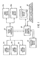
- a digital imaging system which includes an image capture device 10a, an digital image processor 20, an image output device 30a, and a general control computer 40.
- the system may include a monitor device 50 such as a computer console or paper printer.
- the system may also include an input device control for an operator such as a keyboard and or mouse pointer 60.
- Multiple capture devices 10a, 10b, and 10c are shown illustrating that the present invention may be used for digital images derived from a variety of imaging devices. For example, FIG.
- the digital image processor 20 provides the means for processing the digital images to produce pleasing looking images on the intended output device or media.
- Multiple image output devices 30a and 30b are shown illustrating that the present invention may be used in conjunction with a variety of output devices which may include a digital photographic printer and soft copy display.
- the digital image processor processes the digital image to adjust the overall brightness, tone scale, image structure and so forth of the digital image in a manner such that a pleasing looking image is produced by an image output device 30a.
- the present invention is not limited to just these mentioned image processing modules.
- the general control computer 40 shown in FIG. 1 may store the present invention as a computer program stored in a computer readable storage medium, which may comprise, for example: magnetic storage media such as a magnetic disk (such as a floppy disk) or magnetic tape; optical storage media such as an optical disc, optical tape, or machine readable bar code; solid state electronic storage devices such as random access memory (RAM), or read only memory (ROM).
- a computer readable storage medium such as a magnetic disk (such as a floppy disk) or magnetic tape; optical storage media such as an optical disc, optical tape, or machine readable bar code; solid state electronic storage devices such as random access memory (RAM), or read only memory (ROM).
- RAM random access memory
- ROM read only memory
- the present invention implemented in a combination of software and/or hardware is not limited to devices which are physically connected and/or located within the same physical location.
- One or more of the devices illustrated in FIG. 1 may be located remotely and may be connected via a wireless connection.
- a digital image is comprised of one or more digital image channels.
- Each digital image channel is comprised of a two-dimensional array of pixels.
- Each pixel value relates to the amount of light received by the image capture device 10 corresponding to the geometrical domain of the pixel.
- a digital image will typically consist of red, green, and blue digital image channels. Other configurations are also practiced, for example cyan, magenta, and yellow digital image channels.
- the digital image consists of one digital image channel.
- Motion imaging applications can be thought of as a time sequence of digital images. Those skilled in the art will recognize that the present invention can be applied to, but is not limited to, a digital image channel for any of the above mentioned applications.
- the present invention can be applied to any two dimensional array of noise corrupted data to obtain an estimated noise table.
- the present invention describes a digital image channel as a two dimensional array of pixel values arranged by rows and columns, those skilled in the art will recognize that the present invention can be applied to mosaic (non rectilinear) arrays with equal effect.
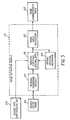
- the digital image processor 20 shown in FIG. 1 is illustrated in more detail in FIG. 2 .
- the general form of the digital image processor 20 employed by the present invention is a cascaded chain of image processing modules.
- the source digital image 201 is received by the digital image processor 20 which produces on output an enhanced digital image 204 and an estimated noise characteristic table 207.
- the noise estimation module 110 receives the source digital image 201 and the default residual histogram 205 and produces an estimated noise characteristic table 207 and an updated residual histogram.
- the updated residual histogram replaces the default residual histogram 205 for the next source digital image 201 to be processed.
- Each image processing module contained within the digital image processor 20 receives a digital image, modifies the digital image, produces a processed digital image and passes the processed digital image to the next image processing module.
- the two enhancement transform modules shown within the digital image processor 20 are a noise reduction module 22 and a spatial sharpening module 23. These two modules use the estimated noise characteristic table 207 produced by the noise estimation module 110 to produce the enhanced digital image 204. Those skilled in the art will recognize that any other image processing module that utilizes an estimated noise characteristic table 207 can be used with the present invention.
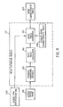
- the noise estimation module shown in FIG. 2 is illustrated in more detail in FIG. 3 .
- the residual transform module 120 receives the source digital image 201 and applies a spatial filter to the source digital image 201 which results in a residual digital image.
- the residual statistics accumulator 130 receives the residual digital image and calculates a set of local residual histograms from the pixel data of the residual digital image.
- the residual statistics accumulator 130 also receives a set of default residual histograms 205 and combines the set of local residual histograms and the set of default residual histograms 205 to produce a set of updated residual histograms.
- the noise table calculator 140 receives the updated residual histograms and produces a noise characteristic table 207.
- the residual transform module 120 performs a spatial filtering operation on the pixel data of the source digital image 201. That is, a residual pixel value is generated for each original pixel value in the source digital image 201.
- the residual pixel values constitute the residual digital image.
- For each pixel of interest a combination of pixel values sampled from a local region of pixels is used to form the residual pixel value.
- the residual transform module 120 performs the spatial filtering operation on each color digital image channel and forms a residual pixel value for each pixel of each color digital image channel.
- the preferred embodiment of the present invention uses a two-dimensional Laplacian operator as the spatial filter to form the residual pixel values.
- the Laplacian operator calculates a local arithmetic mean value from the value of pixel sampled from the local region of pixels about the pixel of interest and subtracts the value of the pixel of interest from the local arithmetic mean value. A local region of 3 by 3 pixels is used.
- the Laplacian operator is convolution spatial filter with an associated convolution kernel of: 1 1 1 1 - 1 1 1 1 1 .
- the preferred embodiment of the present invention uses a two dimensional Laplacian based spatial filter, those skilled in the art will recognize that the present invention can be practiced with other spatial filters, such as but not limited to, one-dimensional Laplacian spatial filters.
- An alternative embodiment of the present invention uses the method disclosed by Snyder and others in commonly-assigned US-A-5,923,775 .
- a similar technique of forming a residual pixel value is performed.
- a gradient signal is calculated using a spatial filter.
- the gradient signal is analyzed to form a masking signal that is used to reject some of the residual pixel values from later consideration.
- this alternative embodiment leads to more accurate noise estimation it is also more computationally intensive than the preferred embodiment.
- the residual statistics accumulator 130 shown in FIG. 3 is described in more detail.
- the pixel data of the source digital image 201 can be conceptualized as having two components - a signal component relating to photographed objects and a noise component.
- the resulting residual pixel values have statistical properties that have a closer relationship to the noise component of the pixel data of the source digital image 201 than the signal component.
- the noise component can contain sub-components, the stochastic subcomponent of the noise component is well modeled by a zero mean Gaussian probability distribution function.
- the noise component of the pixel data of the source digital image 201 can be characterized by a standard deviation and a mean value of zero.
- standard deviation of the noise component can be modeled as being signal and color channel dependent.
- the residual transform module 130 analyzes the residual pixel values and records these values in the form of a set of local residual histograms as a function of the color digital image channel and pixel value. Therefore a given local residual histogram H ik relates to the i th color digital image channel and the k th pixel value sub-range. For each pixel of interest denoted by p mn (corresponding to the m th row and n th column location) in the processed color digital image channel, a histogram bin index k is computed. For example, if the numerical range of pixel values is from 0 to 255 there can be as many as 256 useful histograms, that is one histogram for each possible numerical pixel value.
- the preferred embodiment of the present invention uses 8 histograms to cover the numerical pixel value range of 0 to 255.
- Table (1) histogram bin index sub-range pixel values average pixel value 0 0 to 31 16 1 32 to 63 48 2 64 to 95 80 3 96 to 127 112 4 128 to 159 144 5 160 to 191 176 6 192 to 233 208 7 234 to 255 240 Those skilled in the art will recognize that the present invention can be practiced with digital image pixel data with any numerical range. The number of local residual histograms used for each color digital image channel will depend on the accuracy of results required for the particular digital imaging application.
- each local residual histogram records statistical information for a range of pixel values for a given color digital image channel
- the local residual histogram records the frequency of residual pixel values associated with each pixel of interest p mn . Since the expected mean of the distribution of residual pixel values is zero, the residual pixel values exhibit both positive and negative values. Therefore, the local residual histogram must record the frequency, that is the number of instances of residual pixel values, of all possible instances of residual pixel values. For the example above, the residual pixel values can range from -255 to +255. While is possible to construct local residual histograms with as many recording bins as there are possible instances of residual pixel values, in general this is not necessary.
- the present invention uses 101 total recording bins for each local residual histogram. On of the recording bins corresponds to residual pixel values of 50 and greater. Similarly, one other recording bin corresponds to residual pixel values of -50 and lower. The other 99 recording bins each correspond to a single residual pixel value for the numerical range from -49 to +49.
- the residual statistics accumulator 130 combines the data contained in the local residual histograms with data contained in the default residual histograms 205. While the local residual histograms record residual pixel values as derived from the currently processed source digital image 201, the default residual histograms 205 record the residual pixel values as derived from the previously processed digital images. Thus the default residual histograms 205 have the same form as the local residual histogram, that is one local residual histogram for each pixel value sub-range of each color digital image channel.
- the present invention uses more than one method of combining the local residual histograms with the default residual histograms 205, however, each method combines a single local residual histogram with the corresponding default residual histogram 205. Therefore, it is appropriate to discuss the method with respect to the combination of two histograms with the assumption that each combining method is repeated for all the pairs of corresponding histograms.
- the preferred embodiment of the present invention uses a direct method of combining the data contained in the local residual histogram and default residual histogram 205. That is, the numbers contained in each recording cell of the local residual histogram are added directly to the corresponding recording cell of the default residual histogram 205. Thus after the combining step has been performed, the updated values of each recording cell is given by the sum of the previous value of the recording cell with the value contained in the corresponding recording cell of the local residual histogram.
- the recording cells of the default residual histogram 205 contains the sum total of residual pixel values derived from the source digital image 201 as well as previous processed digital images, the numerical range of the computer implementation can be exceeded. To avoid a numerical overflow condition the default residual histogram 205 can be re-normalized.
- the process of re-normalization includes scanning the values of the recording cells to determine the maximum value, comparing this maximum value to a predetermined allowable value. If the maximum value is greater than the a predetermined allowable value the values of all the recording cells are divided by a constant numerical factor.
- This process of re-normalization of the default residual histogram 205 can be performed either before or after the process of combining the local residual histogram with the default residual histogram 205.
- the preferred embodiment of the present invention performs the re-normalization process before the combining process.
- the noise table calculator 140 receives the updated residual histograms and calculates a noise characteristic table 207. For each of the updated residual histograms relating to a particular color digital image channel and pixel value range, the noise table calculator 140 derives a noise standard deviation value from the value of the recording cells of the updated residual histogram.
- x V k
- x m 1 / N ⁇ ⁇ k x
- N the total number of residual pixel values recorded by the updated residual histogram given by equation (6).
- N ⁇ k RC v k
- An alternative embodiment of the present invention performs an alpha-trimmed standard deviation calculation.
- a first approximation to the standard deviation ⁇ e is calculated using the method described above.
- the calculation of ⁇ n is then calculated using the only recording cells with corresponding residual pixel values that are within a limited range of zero.
- This alternative embodiment of the present invention is more computationally intensive than the preferred embodiment but does yield more accurate results via the rejection of out-lying residual pixel values from adversely contributing to the calculation of the standard deviation ⁇ n value.
- Table 2 below is an example of a noise characteristic table produced with the present invention.
- Table (2) average pixel value Standard deviation of red channel Standard deviation of green channel Standard deviation of blue channel 16 3.28 3.62 3.21 48 3.71 3.20 3.38 80 3.77 4.14 4.50 112 4.57 4.35 4.21 144 4.98 4.25 4.37 176 5.05 4.11 6.21 208 5.05 5.64 6.29 240 2.71 4.27 3.87
- the present invention uses a set of residual histograms to record the calculated statistics.
- a set of histograms is an example of a statistical table from which a noise characteristic table can be derived.
- the set of local residual histograms constitutes a local statistical table
- the set of default residual histograms 205 constitutes a default statistical table
- the set of updated residual histograms constitutes an updated statistical table.
- the residual digital images could be stored and serve as a statistical table.
- FIG. 4 shows the details of an alternative embodiment of the noise estimation module 110.
- the residual transform module 120 receives the source digital image 201 and calculates a residual digital image.
- the residual statistics accumulator 130 receives the residual digital image and calculates a set of local residual histograms from the pixel data of the residual digital image as described above.
- the noise table calculator 140 receives the local residual histograms and produces a local noise characteristic table.
- the noise table generator 150 receives the local noise characteristic table and the default noise characteristic table 208 and produces an updated noise characteristic table 207.
- This updated noise characteristic table 207 replaces the default noise characteristic table 208 for the next source digital image 201 to be processed.
- the local noise characteristic table and default noise characteristic table 208 are combined by calculating a linear combination of these two tables element for element. Good values for the linear combination coefficients are 0.99 contribution for the default noise characteristic table 208 values and 0.01 for the local noise characteristic table values.
- the calculated noise characteristic table 207 is used in conjunction with spatial filters to produce an enhanced digital image 204 from the source digital image 201.
- a spatial filter is any method which uses pixel values sampled from a local region about a pixel of interest to calculate an enhanced pixel value which replaces the pixel of interest.
- Those spatial filters which reduce spatial modulation, for at least some pixels in an effort to remove noise from the processed digital image can be considered noise reduction filters.
- Those spatial filters which increase spatial modulation, for at least some pixels in an effort to enhance spatial detail noise in the processed digital image can be considered spatial sharpening filters. It should be noted that it is possible for a single spatial filter to be considered both a noise reduction filter as well as a spatial sharpening filter.
- the present invention can be used with any digital image processing method which makes uses of a noise characteristic table to produce an enhanced digital image 204.
- the preferred embodiment of the present invention employs a noise reduction module 22 as part of the image processing method to produce an enhanced digital image 204.
- the source digital image 201 and the noise characteristic table 207 are received by the noise reduction module 22 which produces on output a noise reduced digital image.
- the present invention uses a modified implementation of the Sigma filter, described by Jong-Sen Lee in the journal article Digital Image Smoothing and the Sigma Filter, Computer Vision, Graphics, and Image Processing Vol 24, p. 255-269, 1983, as a noise reduction filter to enhance the appearance of the processed digital image.
- the values of the pixels contained in a sampled local region, n by n pixels where n denotes the length of pixels in either the row or column direction, are compared with the value of the center pixel, or pixel of interest.
- Each pixel in the sampled local region is given a weighting factor of one or zero based on the absolute difference between the value of the pixel of interest and the local region pixel value.
- the weighting factor if set to one. Otherwise, the weighting factor is set to zero.
- the numerical constant ⁇ is set to two times the expected noise standard deviation.
- p ij represents the ij th pixel contained in the sampled local region
- p mn represents the value of the pixel of interest located at row m and column n
- a ij represents a weighting factor
- q mn represents the noise reduced pixel value.
- a rectangular sampling region centered about the
- the parameter Sfac is termed a scale factor can be used to vary the degree of noise reduction.
- the calculation of the noise reduced pixel value q mn as the division of the two sums is then calculated. The process is completed for some or all of the pixels contained in the digital image channel and for some or all the digital image channels contained in the digital image.
- the noise reduced pixel values constitute the noise reduced digital image.
- the modified implementation of the Sigma filter is an example of a noise reduction method that uses a noise characteristic table.
- the preferred embodiment of the present invention employs a spatial sharpening module 23 as part of the image processing method to produce an enhanced digital image 204.
- the noise reduced digital image and the noise characteristic table 207 are received by the spatial sharpening module 23 which produces on output an enhanced digital image 204.
- the preferred embodiment uses a modified implementation of the method described by Kwon et al in US-A-5,081,692 .
- This spatial sharpening method performs an un-sharp masking operation by filtering the input digital image with a spatial averaging 2-dimensional Gaussian filter (characterized by a standard deviation of 2.0 pixels) which results in a blurred digital image.
- the blurred digital image is subtracted from the input digital image to form a high-pass residual.
- a local variance about a pixel of interest is calculated by using the pixel data from the high-pass residual. Based on the value of the local variance a sharpening factor is adjusted so as to amplify large signals more than small amplitude signals.
- the amplification factor ⁇ is therefore a factor of the local variance ⁇ . that is ⁇ ( ⁇ ).
- the present invention modifies the method taught by Kwon and others to make the amplification factor ⁇ ( ⁇ ) a function of the estimated noise, that is ⁇ ( ⁇ , ⁇ n ).
- the amplification function ⁇ is given by a gamma function, or integral of a Gaussian probability function, as given by equation (11).
- ⁇ v y o + y max ⁇ ⁇ e - v - v o ⁇ 2 / 2 ⁇ ⁇ ⁇ 2 y o + y max ⁇ ⁇ e - v max - v o ⁇ 2 / 2 ⁇ ⁇ ⁇ 2
- y O represents a minimum amplification factor
- y max represents a maximum amplification factor
- ⁇ max represents a maximum abscissa value of the variable ⁇
- ⁇ O represents a transition parameter
- ⁇ represents a transition rate parameter.
- the optimal values for the variables used in equation (13) depend on the digital imaging application.
- the present invention uses a value of 1.0 for y O which results in no spatial sharpening for noisy regions. A value of 3.0 is used for y max , however, this variable is sensitive to user preference with values ranging from 2.0 to 4.0 producing acceptable results.
- the value of Sfac 2 should be set to between 1.0 and 2.0 with 1.5 as optimal.
- the variable s should be set to values in the range from v O / 2 to v O / 10 for reasonable results.
- the variable ⁇ max should be set to a value much larger than the expected noise, for example 20 time the
- the image capture device 10a and 10b shown in FIG. 1 could be a photographic film scanner while the image capture device 10c could be a digital camera or digital camcorder.
- the image capture device can contribute add noise to the digital images it produces, the inherent noise in the capture medium usually dominates the overall noise characteristics of the resultant digital images.
- a photographic film scanner can produce digital images from any photographic film sample, in general, some photographic films are inherently noisier that others.
- a photographic film sample is an example of a photographic image.
- Other examples of photographic images can include, but are not limited to, a CCD imaging electronic device and a photographic print.
- the image capture devices 10a, 10b, and 10c shown in FIG. 1 are capable of producing a source type identification tag 202 which uniquely identifies the source digital image 201 as belonging to a particular group.
- a photographic film sample Kodak Generation 6 Gold 200 film is scanned by the image capture device 10a which produces a source digital image 201 and a source type identification tag 202.
- the source type identification tag 202 identifies the source digital image 201 as being derived from Kodak Generation 6 Gold 200 film.
- a default statistical tables is used in conjunction with the pixels from the source digital image 201 to produce a noise characteristic table 207 for the source digital image 201 as described above.
- the digital imaging system shown in FIG.1 , stores a default statistical table corresponding to each unique a source type identification tag 202.
- the default statistical table corresponding to Kodak Generation 6 Gold 200 film is used to process the source digital image 201 derived from the scanning the Kodak Generation 6 Gold 200 film sample with the image capture device 10a. It is important to note that if a different sample of Kodak Generation 6 Gold 200 film is scanned by the image capture device 10b, the same default statistical table corresponding to Kodak Generation 6 Gold 200 film is used. Thus the default statistical table is selected on the basis of the type photographic film and not on the type of or individual unit image capture device.
- This feature of the present invention allows the default statistical table, and consequently the resultant calculated noise characteristic table 207, to track or relate to the type of photographic film manufactured. Since the present invention automatically updates the default statistical tables and can derive the default statistical tables from the pixel values of digital images, the present invention can be used with new types of manufactured photographic film without the need of a disseminated data base of either statistical tables or noise characteristic tables.
- the image capture device 10c can be a digital still camera, such as the Kodak DCS 290.
- the image capture device 10c produces a unique source type identification tag 202. In this manner any newly produced digital camera which produces a new and unique source type identification tag 202 can be processed effectively with the present invention.
- a new default statistical table is created.
- the digital imaging system shown in FIG. 1 maintains a separate database of default statistical tables, one for each source identification tag, for each image capture device 10a and 10b. Since the image capture device can contribute some noise to the digital images it produces, maintaining separate databases of default statistical tables for each image capture device results in more accurate noise characteristic tables.
- the calculated noise characteristic table 207 is stored with the source digital image 201 as meta-data, that is non-pixel information.
- the source digital image 201 with meta-data can be transmitted to a remote site or stored for safe keeping to be used at a later time or another site.
- Any of the above mentioned noise characteristic tables (the local noise characteristic table, the default characteristic table or the updated characteristic table) can be stored as meta-data.
- a noise characteristic table requires much less memory storage than a set of residual histograms.
- a set of residual histograms is stored with the source digital image 201 as meta-data.
- the method further including the step of using the noise characteristic table and a noise reduction filter to calculate an enhanced digital image.
- the method further including the step of using noise characteristic table and a spatial sharpening filter to calculate an enhanced digital image.
- the method further including the step of using noise characteristic table, a noise reduction filter and a spatial sharpening filter to calculate an enhanced digital image.
- the method wherein the first statistical table is either an initial default statistical table or an updated third statistical table.
- the method wherein the initial default statistical table relates to a noise estimate of that noise which will be provided by the image source in capturing the image.
- first, second, and third statistical tables each include a series of standard deviation values for different ranges of intensities provided by the captured image source.
- first, second, and third statistical tables each include at least one histogram.
- first, second, and third statistical tables each include a series of histograms for different ranges of intensities provided by the captured image source.
- the method wherein the noise characteristic is use in processing the digital image for enhancing such digital image.
- the method further including the step of using the noise characteristic table and a noise reduction filter to calculate an enhanced digital image.
- the method further including the step of using noise characteristic table and a spatial sharpening filter to calculate an enhanced digital image.
- the method further including the step of using noise characteristic table, a noise reduction filter and a spatial sharpening filter to calculate an enhanced digital image.
Landscapes
- Engineering & Computer Science (AREA)
- Physics & Mathematics (AREA)
- General Physics & Mathematics (AREA)
- Theoretical Computer Science (AREA)
- Multimedia (AREA)
- Image Processing (AREA)
- Facsimile Image Signal Circuits (AREA)
- Image Analysis (AREA)
- Testing, Inspecting, Measuring Of Stereoscopic Televisions And Televisions (AREA)
Applications Claiming Priority (2)
| Application Number | Priority Date | Filing Date | Title |
|---|---|---|---|
| US09/712,365 US7054501B1 (en) | 2000-11-14 | 2000-11-14 | Estimating noise for a digital image utilizing updated statistics |
| US712365 | 2000-11-14 |
Publications (3)
| Publication Number | Publication Date |
|---|---|
| EP1205878A2 EP1205878A2 (en) | 2002-05-15 |
| EP1205878A3 EP1205878A3 (en) | 2003-06-11 |
| EP1205878B1 true EP1205878B1 (en) | 2012-06-27 |
Family
ID=24861804
Family Applications (1)
| Application Number | Title | Priority Date | Filing Date |
|---|---|---|---|
| EP01204221A Expired - Lifetime EP1205878B1 (en) | 2000-11-14 | 2001-11-02 | Estimating noise for a digital image utilizing updated statistics |
Country Status (3)
| Country | Link |
|---|---|
| US (1) | US7054501B1 (enExample) |
| EP (1) | EP1205878B1 (enExample) |
| JP (1) | JP4012720B2 (enExample) |
Families Citing this family (25)
| Publication number | Priority date | Publication date | Assignee | Title |
|---|---|---|---|---|
| US6788824B1 (en) * | 2000-09-29 | 2004-09-07 | Adobe Systems Incorporated | Creating image-sharpening profiles |
| JP3762725B2 (ja) * | 2002-08-22 | 2006-04-05 | オリンパス株式会社 | 撮像システムおよび画像処理プログラム |
| US7599882B2 (en) * | 2003-11-14 | 2009-10-06 | First American Corelogic, Inc. | Method for mortgage fraud detection |
| KR100624862B1 (ko) * | 2004-01-02 | 2006-09-18 | 엘지전자 주식회사 | 영상 처리 장치 및 그 방법 |
| US7356195B2 (en) | 2004-04-29 | 2008-04-08 | Hewlett-Packard Development Company, L.P. | System and method for estimating image sharpness |
| US7266246B2 (en) | 2004-04-29 | 2007-09-04 | Hewlett-Packard Development Company, L.P. | System and method for estimating compression noise in images |
| US7570831B2 (en) | 2004-04-29 | 2009-08-04 | Hewlett-Packard Development Company, L.P. | System and method for estimating image noise |
| US7372597B2 (en) | 2004-07-27 | 2008-05-13 | Eastman Kodak Company | Tonescales for geographically localized digital rendition of people |
| JP4999392B2 (ja) * | 2006-07-28 | 2012-08-15 | キヤノン株式会社 | 画像処理装置及びその制御方法、並びに、コンピュータプログラム及びコンピュータ可読記憶媒体 |
| US8018504B2 (en) * | 2006-12-22 | 2011-09-13 | Eastman Kodak Company | Reduction of position dependent noise in a digital image |
| US20080212890A1 (en) * | 2007-01-10 | 2008-09-04 | Loubachevskaia Natalya Y | Systems and Methods for Noise Estimation in a Single Frame of Video Data |
| US7889942B2 (en) * | 2007-05-25 | 2011-02-15 | Zoran Corporation | Dynamic range compensation-dependent noise reduction |
| US7995856B2 (en) | 2007-05-25 | 2011-08-09 | Zoran Corporation | Dynamic range compensation-dependent noise reduction |
| US8824831B2 (en) | 2007-05-25 | 2014-09-02 | Qualcomm Technologies, Inc. | Advanced noise reduction in digital cameras |
| US7983503B2 (en) | 2007-05-25 | 2011-07-19 | Zoran Corporation | Advanced noise reduction in digital cameras |
| JP5491073B2 (ja) * | 2009-05-22 | 2014-05-14 | キヤノン株式会社 | 画像処理装置、画像処理方法及びプログラム |
| JP2012141812A (ja) * | 2010-12-29 | 2012-07-26 | Sony Corp | 画像処理装置、画像処理方法、およびプログラム |
| WO2014070273A1 (en) * | 2012-11-02 | 2014-05-08 | Board Of Regents, The University Of Texas System | Recursive conditional means image denoising |
| JP6362333B2 (ja) | 2013-02-14 | 2018-07-25 | キヤノン株式会社 | 画像処理装置、画像処理方法、およびプログラム |
| JP6625165B2 (ja) | 2013-02-14 | 2019-12-25 | キヤノン株式会社 | 画像処理装置、画像処理方法、およびプログラム |
| US10719916B2 (en) | 2018-08-02 | 2020-07-21 | Apple Inc. | Statistical noise estimation systems and methods |
| US11321813B2 (en) | 2018-08-02 | 2022-05-03 | Apple Inc. | Angular detection using sum of absolute difference statistics systems and methods |
| US11024012B2 (en) | 2018-08-02 | 2021-06-01 | Apple Inc. | Directional scaling systems and methods |
| US10762604B2 (en) | 2018-08-02 | 2020-09-01 | Apple Inc. | Chrominance and luminance enhancing systems and methods |
| WO2021077121A1 (en) * | 2019-10-18 | 2021-04-22 | Warner Bros. Entertainment Inc. | Scanner noise elimination for scanned films |
Family Cites Families (7)
| Publication number | Priority date | Publication date | Assignee | Title |
|---|---|---|---|---|
| US5729631A (en) * | 1993-11-30 | 1998-03-17 | Polaroid Corporation | Image noise reduction system using a wiener variant filter in a pyramid image representation |
| JPH09214807A (ja) * | 1996-01-31 | 1997-08-15 | Canon Inc | 画像処理装置および画像処理方法 |
| US5923775A (en) | 1996-04-04 | 1999-07-13 | Eastman Kodak Company | Apparatus and method for signal dependent noise estimation and reduction in digital images |
| US5809178A (en) | 1996-06-11 | 1998-09-15 | Apple Computer, Inc. | Elimination of visible quantizing artifacts in a digital image utilizing a critical noise/quantizing factor |
| US6128415A (en) * | 1996-09-06 | 2000-10-03 | Polaroid Corporation | Device profiles for use in a digital image processing system |
| US6069982A (en) | 1997-12-23 | 2000-05-30 | Polaroid Corporation | Estimation of frequency dependence and grey-level dependence of noise in an image |
| US6118906A (en) | 1998-02-03 | 2000-09-12 | Eastman Kodak Company | Sharpening system adjusted for measured noise of photofinishing images |
-
2000
- 2000-11-14 US US09/712,365 patent/US7054501B1/en not_active Expired - Fee Related
-
2001
- 2001-11-02 EP EP01204221A patent/EP1205878B1/en not_active Expired - Lifetime
- 2001-11-13 JP JP2001347438A patent/JP4012720B2/ja not_active Expired - Fee Related
Also Published As
| Publication number | Publication date |
|---|---|
| JP4012720B2 (ja) | 2007-11-21 |
| JP2002216127A (ja) | 2002-08-02 |
| EP1205878A2 (en) | 2002-05-15 |
| EP1205878A3 (en) | 2003-06-11 |
| US7054501B1 (en) | 2006-05-30 |
Similar Documents
| Publication | Publication Date | Title |
|---|---|---|
| EP1205878B1 (en) | Estimating noise for a digital image utilizing updated statistics | |
| US6931160B2 (en) | Method of spatially filtering digital image for noise removal, noise estimation or digital image enhancement | |
| US7092579B2 (en) | Calculating noise estimates of a digital image using gradient analysis | |
| US6937775B2 (en) | Method of enhancing the tone scale of a digital image to extend the linear response range without amplifying noise | |
| US6804393B2 (en) | Method of calculating noise from a digital image utilizing color cross correlation statistics | |
| US6681054B1 (en) | Noise reduction method utilizing probabilistic weighting, apparatus, and program for digital image processing | |
| US7065255B2 (en) | Method and apparatus for enhancing digital images utilizing non-image data | |
| KR102261532B1 (ko) | 단일 스케일 영상 융합에 기반한 안개 제거 시스템 및 방법 | |
| US7856150B2 (en) | Denoise method on image pyramid | |
| US6934421B2 (en) | Calculating noise from multiple digital images having a common noise source | |
| US6707950B1 (en) | Method for modification of non-image data in an image processing chain | |
| US6611627B1 (en) | Digital image processing method for edge shaping | |
| US6718068B1 (en) | Noise reduction method utilizing statistical weighting, apparatus, and program for digital image processing | |
| EP1227437B1 (en) | A multiresolution based method for removing noise from digital images | |
| US6069982A (en) | Estimation of frequency dependence and grey-level dependence of noise in an image | |
| JP4460839B2 (ja) | デジタル画像鮮鋭化装置 | |
| EP1398733A1 (en) | Texture-based colour correction | |
| CA2298738A1 (en) | Apparatus and methods for image and signal processing | |
| US20020126910A1 (en) | Method of calculating noise from multiple digital images utilizing common noise characteristics | |
| US20030161547A1 (en) | Systems and methods for processing a digital image | |
| Phelippeau et al. | Shot noise adaptive bilateral filter | |
| Sezan et al. | Tutorial review of recent developments in digital image restoration | |
| Azimi-Sadjadi et al. | Neural network decision directed edge-adaptive Kalman filter for image estimation | |
| Yap et al. | A recursive approach to joint image restoration and compensated blur identification | |
| Kasthuri | Mean Filtering to De-Noising Image Using Various Block Size |
Legal Events
| Date | Code | Title | Description |
|---|---|---|---|
| PUAI | Public reference made under article 153(3) epc to a published international application that has entered the european phase |
Free format text: ORIGINAL CODE: 0009012 |
|
| AK | Designated contracting states |
Kind code of ref document: A2 Designated state(s): AT BE CH CY DE DK ES FI FR GB GR IE IT LI LU MC NL PT SE TR |
|
| AX | Request for extension of the european patent |
Free format text: AL;LT;LV;MK;RO;SI |
|
| PUAL | Search report despatched |
Free format text: ORIGINAL CODE: 0009013 |
|
| AK | Designated contracting states |
Designated state(s): AT BE CH CY DE DK ES FI FR GB GR IE IT LI LU MC NL PT SE TR |
|
| AX | Request for extension of the european patent |
Extension state: AL LT LV MK RO SI |
|
| RIC1 | Information provided on ipc code assigned before grant |
Ipc: 7H 04N 1/409 B Ipc: 7G 06T 5/20 B Ipc: 7G 06T 5/00 A |
|
| 17P | Request for examination filed |
Effective date: 20031112 |
|
| AKX | Designation fees paid |
Designated state(s): DE FR GB |
|
| 17Q | First examination report despatched |
Effective date: 20090813 |
|
| GRAP | Despatch of communication of intention to grant a patent |
Free format text: ORIGINAL CODE: EPIDOSNIGR1 |
|
| RIC1 | Information provided on ipc code assigned before grant |
Ipc: G06T 5/00 20060101AFI20120105BHEP Ipc: G06K 9/40 20060101ALI20120105BHEP Ipc: H04N 1/409 20060101ALI20120105BHEP |
|
| GRAS | Grant fee paid |
Free format text: ORIGINAL CODE: EPIDOSNIGR3 |
|
| GRAA | (expected) grant |
Free format text: ORIGINAL CODE: 0009210 |
|
| AK | Designated contracting states |
Kind code of ref document: B1 Designated state(s): DE FR GB |
|
| REG | Reference to a national code |
Ref country code: GB Ref legal event code: FG4D |
|
| REG | Reference to a national code |
Ref country code: DE Ref legal event code: R096 Ref document number: 60146770 Country of ref document: DE Effective date: 20120823 |
|
| REG | Reference to a national code |
Ref country code: DE Ref legal event code: R082 Ref document number: 60146770 Country of ref document: DE Representative=s name: MUELLER-BORE & PARTNER PATENTANWAELTE, EUROPEA, DE |
|
| PLBE | No opposition filed within time limit |
Free format text: ORIGINAL CODE: 0009261 |
|
| STAA | Information on the status of an ep patent application or granted ep patent |
Free format text: STATUS: NO OPPOSITION FILED WITHIN TIME LIMIT |
|
| 26N | No opposition filed |
Effective date: 20130328 |
|
| REG | Reference to a national code |
Ref country code: DE Ref legal event code: R082 Ref document number: 60146770 Country of ref document: DE Representative=s name: MUELLER-BORE & PARTNER PATENTANWAELTE, EUROPEA, DE Effective date: 20130430 Ref country code: DE Ref legal event code: R081 Ref document number: 60146770 Country of ref document: DE Owner name: INTELLECTUAL VENTURES FUND 83 LLC (N.D.GES.D.S, US Free format text: FORMER OWNER: EASTMAN KODAK CO., ROCHESTER, US Effective date: 20120628 Ref country code: DE Ref legal event code: R081 Ref document number: 60146770 Country of ref document: DE Owner name: INTELLECTUAL VENTURES FUND 83 LLC (N.D.GES.D.S, US Free format text: FORMER OWNER: EASTMAN KODAK COMPANY, ROCHESTER, US Effective date: 20130430 Ref country code: DE Ref legal event code: R081 Ref document number: 60146770 Country of ref document: DE Owner name: INTELLECTUAL VENTURES FUND 83 LLC (N.D.GES.D.S, US Free format text: FORMER OWNER: EASTMAN KODAK CO., ROCHESTER, N.Y., US Effective date: 20120628 Ref country code: DE Ref legal event code: R082 Ref document number: 60146770 Country of ref document: DE Representative=s name: MUELLER-BORE & PARTNER PATENTANWAELTE PARTG MB, DE Effective date: 20130430 Ref country code: DE Ref legal event code: R081 Ref document number: 60146770 Country of ref document: DE Owner name: INTELLECTUAL VENTURES FUND 83 LLC (N.D.GES.D.S, US Free format text: FORMER OWNER: EASTMAN KODAK COMPANY, ROCHESTER, N.Y., US Effective date: 20130430 |
|
| REG | Reference to a national code |
Ref country code: DE Ref legal event code: R097 Ref document number: 60146770 Country of ref document: DE Effective date: 20130328 |
|
| REG | Reference to a national code |
Ref country code: GB Ref legal event code: 732E Free format text: REGISTERED BETWEEN 20130711 AND 20130717 |
|
| REG | Reference to a national code |
Ref country code: FR Ref legal event code: TP Owner name: INTELLECTUAL VENTURES FUND 83 LLC, US Effective date: 20130919 |
|
| REG | Reference to a national code |
Ref country code: FR Ref legal event code: PLFP Year of fee payment: 15 |
|
| REG | Reference to a national code |
Ref country code: FR Ref legal event code: PLFP Year of fee payment: 16 |
|
| REG | Reference to a national code |
Ref country code: FR Ref legal event code: PLFP Year of fee payment: 17 |
|
| PGFP | Annual fee paid to national office [announced via postgrant information from national office to epo] |
Ref country code: FR Payment date: 20171127 Year of fee payment: 17 Ref country code: DE Payment date: 20171129 Year of fee payment: 17 |
|
| PGFP | Annual fee paid to national office [announced via postgrant information from national office to epo] |
Ref country code: GB Payment date: 20171127 Year of fee payment: 17 |
|
| REG | Reference to a national code |
Ref country code: DE Ref legal event code: R119 Ref document number: 60146770 Country of ref document: DE |
|
| GBPC | Gb: european patent ceased through non-payment of renewal fee |
Effective date: 20181102 |
|
| PG25 | Lapsed in a contracting state [announced via postgrant information from national office to epo] |
Ref country code: FR Free format text: LAPSE BECAUSE OF NON-PAYMENT OF DUE FEES Effective date: 20181130 Ref country code: DE Free format text: LAPSE BECAUSE OF NON-PAYMENT OF DUE FEES Effective date: 20190601 |
|
| PG25 | Lapsed in a contracting state [announced via postgrant information from national office to epo] |
Ref country code: GB Free format text: LAPSE BECAUSE OF NON-PAYMENT OF DUE FEES Effective date: 20181102 |