EP1205634B1 - Aube de turbine et sa utilisation - Google Patents
Aube de turbine et sa utilisation Download PDFInfo
- Publication number
- EP1205634B1 EP1205634B1 EP01309235A EP01309235A EP1205634B1 EP 1205634 B1 EP1205634 B1 EP 1205634B1 EP 01309235 A EP01309235 A EP 01309235A EP 01309235 A EP01309235 A EP 01309235A EP 1205634 B1 EP1205634 B1 EP 1205634B1
- Authority
- EP
- European Patent Office
- Prior art keywords
- platform
- turbine blade
- turbine
- cavity
- cooling
- Prior art date
- Legal status (The legal status is an assumption and is not a legal conclusion. Google has not performed a legal analysis and makes no representation as to the accuracy of the status listed.)
- Expired - Lifetime
Links
Images

Classifications
-
- F—MECHANICAL ENGINEERING; LIGHTING; HEATING; WEAPONS; BLASTING
- F01—MACHINES OR ENGINES IN GENERAL; ENGINE PLANTS IN GENERAL; STEAM ENGINES
- F01D—NON-POSITIVE DISPLACEMENT MACHINES OR ENGINES, e.g. STEAM TURBINES
- F01D11/00—Preventing or minimising internal leakage of working-fluid, e.g. between stages
- F01D11/02—Preventing or minimising internal leakage of working-fluid, e.g. between stages by non-contact sealings, e.g. of labyrinth type
- F01D11/04—Preventing or minimising internal leakage of working-fluid, e.g. between stages by non-contact sealings, e.g. of labyrinth type using sealing fluid, e.g. steam
-
- F—MECHANICAL ENGINEERING; LIGHTING; HEATING; WEAPONS; BLASTING
- F01—MACHINES OR ENGINES IN GENERAL; ENGINE PLANTS IN GENERAL; STEAM ENGINES
- F01D—NON-POSITIVE DISPLACEMENT MACHINES OR ENGINES, e.g. STEAM TURBINES
- F01D5/00—Blades; Blade-carrying members; Heating, heat-insulating, cooling or antivibration means on the blades or the members
- F01D5/02—Blade-carrying members, e.g. rotors
- F01D5/08—Heating, heat-insulating or cooling means
- F01D5/081—Cooling fluid being directed on the side of the rotor disc or at the roots of the blades
-
- F—MECHANICAL ENGINEERING; LIGHTING; HEATING; WEAPONS; BLASTING
- F01—MACHINES OR ENGINES IN GENERAL; ENGINE PLANTS IN GENERAL; STEAM ENGINES
- F01D—NON-POSITIVE DISPLACEMENT MACHINES OR ENGINES, e.g. STEAM TURBINES
- F01D5/00—Blades; Blade-carrying members; Heating, heat-insulating, cooling or antivibration means on the blades or the members
- F01D5/12—Blades
- F01D5/14—Form or construction
- F01D5/18—Hollow blades, i.e. blades with cooling or heating channels or cavities; Heating, heat-insulating or cooling means on blades
- F01D5/187—Convection cooling
-
- F—MECHANICAL ENGINEERING; LIGHTING; HEATING; WEAPONS; BLASTING
- F05—INDEXING SCHEMES RELATING TO ENGINES OR PUMPS IN VARIOUS SUBCLASSES OF CLASSES F01-F04
- F05D—INDEXING SCHEME FOR ASPECTS RELATING TO NON-POSITIVE-DISPLACEMENT MACHINES OR ENGINES, GAS-TURBINES OR JET-PROPULSION PLANTS
- F05D2240/00—Components
- F05D2240/80—Platforms for stationary or moving blades
- F05D2240/81—Cooled platforms
-
- F—MECHANICAL ENGINEERING; LIGHTING; HEATING; WEAPONS; BLASTING
- F05—INDEXING SCHEMES RELATING TO ENGINES OR PUMPS IN VARIOUS SUBCLASSES OF CLASSES F01-F04
- F05D—INDEXING SCHEME FOR ASPECTS RELATING TO NON-POSITIVE-DISPLACEMENT MACHINES OR ENGINES, GAS-TURBINES OR JET-PROPULSION PLANTS
- F05D2260/00—Function
- F05D2260/20—Heat transfer, e.g. cooling
- F05D2260/202—Heat transfer, e.g. cooling by film cooling
-
- F—MECHANICAL ENGINEERING; LIGHTING; HEATING; WEAPONS; BLASTING
- F05—INDEXING SCHEMES RELATING TO ENGINES OR PUMPS IN VARIOUS SUBCLASSES OF CLASSES F01-F04
- F05D—INDEXING SCHEME FOR ASPECTS RELATING TO NON-POSITIVE-DISPLACEMENT MACHINES OR ENGINES, GAS-TURBINES OR JET-PROPULSION PLANTS
- F05D2260/00—Function
- F05D2260/20—Heat transfer, e.g. cooling
- F05D2260/221—Improvement of heat transfer
- F05D2260/2214—Improvement of heat transfer by increasing the heat transfer surface
- F05D2260/22141—Improvement of heat transfer by increasing the heat transfer surface using fins or ribs
-
- Y—GENERAL TAGGING OF NEW TECHNOLOGICAL DEVELOPMENTS; GENERAL TAGGING OF CROSS-SECTIONAL TECHNOLOGIES SPANNING OVER SEVERAL SECTIONS OF THE IPC; TECHNICAL SUBJECTS COVERED BY FORMER USPC CROSS-REFERENCE ART COLLECTIONS [XRACs] AND DIGESTS
- Y02—TECHNOLOGIES OR APPLICATIONS FOR MITIGATION OR ADAPTATION AGAINST CLIMATE CHANGE
- Y02T—CLIMATE CHANGE MITIGATION TECHNOLOGIES RELATED TO TRANSPORTATION
- Y02T50/00—Aeronautics or air transport
- Y02T50/60—Efficient propulsion technologies, e.g. for aircraft
Definitions
- the present invention relates generally to gas turbine engines, and more particularly to internally cooled turbine rotor blades used in such engines.
- a gas turbine engine includes a compressor that provides pressurized air to a combustor wherein the air is mixed with fuel and ignited for generating hot combustion gases. These gases flow downstream to one or more turbines that extract energy therefrom to power the compressor and provide useful work such as powering an aircraft in flight.
- a turbofan engine which typically includes a fan placed at the front of the core engine, a high pressure turbine powers the compressor of the core engine.
- a low pressure turbine is disposed downstream from the high pressure turbine for powering the fan.
- Each turbine stage commonly includes a stationary turbine nozzle followed in turn by a turbine rotor.
- the turbine rotor comprises a row of rotor blades mounted to the perimeter of a rotor disk that rotates about the centerline axis of the engine.
- Each rotor blade typically includes a shank portion having a dovetail for mounting the blade to the rotor disk and an airfoil that extracts useful work from the hot gases exiting the combustor.
- the turbine nozzles are usually segmented around the circumference thereof to accommodate thermal expansion. Each nozzle segment has one or more nozzle vanes disposed between inner and outer bands for channeling the hot gas stream into the turbine rotor in such a manner that the turbine rotor can do work.
- the high pressure turbine components are exposed to extremely high temperature combustion gases.
- the turbine blades, nozzle vanes and inner and outer bands typically employ internal cooling to keep their temperatures within certain design limits.
- the airfoil of a turbine rotor blade for example, is ordinarily cooled by passing cooling air through an internal circuit.
- the cooling air normally enters through a passage in the blade's root and exits through film cooling holes formed in the airfoil surface, thereby producing a thin layer or film of cooling air that protects the airfoil from the hot gases.
- Known turbine blade cooling circuits often include a plurality of radially oriented passages that are series-connected to produce a serpentine path, thereby increasing cooling effectiveness by extending the length of the coolant flow path.
- Turbine blades according to the state of the art are disclosed in US 5 813 835 or JP 41 166 401 A .
- the vane airfoil includes one or more perforated hollow inserts that are suitably mounted therein. Cooling air is channeled into the inserts and then impinges against the inner surface of the airfoil for impingement cooling thereof. Film cooling is accomplished by passing the cooling air through film cooling holes formed in the vane airfoil so as to produce a thin layer of cooling air on the outer surface of the vane.
- the spaces fore and aft of the rotor disks are in fluid communication with the hot gas stream.
- the rotor disks are also subjected to high temperatures, particularly at the disk rim.
- cooling air is used to purge the fore and aft disk wheel spaces, thereby limiting the ingestion of hot gases.
- the cooling air for each of these cooling applications is usually extracted from the compressor. Because the extracted air leads to an associated thermodynamic loss to the engine cycle, it is desirable to keep the amount of air diverted for cooling to a minimum.
- advanced engine designs with increased thrust-to-weight ratios operate at higher turbine inlet temperatures. The higher temperatures require greater overall turbine cooling and make it necessary to cool the blade platform as well. Accordingly, there is a need for improved cooling of turbine components, including the blade platform, without increasing chargeable cooling flow.
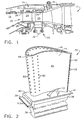
- Figure 1 shows a portion of a gas turbine engine 10 having, among other structures, a combustor 12, a high pressure turbine 14, and a low pressure turbine 16.
- the combustor 12 includes a generally annular hollow body defining a combustion chamber 18 therein.
- a compressor (not shown) provides compressed air that passes primarily into the combustor 12 to support combustion and partially around the combustor 12 where it is used to cool both the combustor liners and turbomachinery further downstream.
- Fuel is introduced into the forward end of the combustor 12 and is mixed with the air in a conventional fashion.
- the resulting fuel-air mixture flows into the combustion chamber 18 where it is ignited for generating hot combustion gases.
- the hot combustion gases are discharged to the high pressure turbine 14 located downstream of the combustor 12 where they are expanded so that energy is extracted.
- the hot gases then flow to the low pressure turbine 16 where they are expanded further.
- the high pressure turbine 14 includes a turbine nozzle 20 and a turbine rotor 22.
- the turbine nozzle 20 includes a plurality of circumferentially spaced vanes 24 (only one shown in Figure 1 ) that are supported between a number of arcuate outer bands 26 and arcuate inner bands 28.
- the vanes 24, outer bands 26 and inner bands 28 are arranged into a plurality of circumferentially adjoining nozzle segments that collectively form a complete 360° assembly.
- the outer and inner bands 26 and 28 of each nozzle segment define the outer and inner radial flowpath boundaries, respectively, for the hot gas stream flowing through the nozzle 20.
- the vanes 24 are configured so as to optimally direct the combustion gases to the turbine rotor 22.
- the turbine rotor 22 includes a plurality of circumferentially spaced apart blades 30 (only one shown in Figure 1 ) extending radially outwardly from a rotor disk 32 that rotates about the centerline axis of the engine 10.
- a plurality of arcuate shrouds 34 is arranged circumferentially in an annular array so as to closely surround the rotor blades 30 and thereby define the outer radial flowpath boundary for the hot gas stream flowing through the turbine rotor 22.
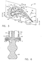
- FIG. 2 An exemplary one of the turbine rotor blades 30 is illustrated in Figure 2 and includes a conventional dovetail 36, which may have any suitable form including tangs that engage complementary tangs of a dovetail slot in the rotor disk 32 for radially retaining the blade 30 to the disk 32 as it rotates during operation.
- a blade shank 38 extends radially upwardly from the dovetail 36 and terminates in a platform 40 that projects laterally outwardly from and surrounds the shank 38.
- the platform 40 includes a forward angel wing 39 and an aft angel wing 41.
- the platforms 40 of adjacent blades 30 abut one another to form a radially inner boundary for the hot gas stream.
- a hollow airfoil 42 extends radially outwardly from the platform 40 and into the hot gas stream.
- the airfoil 42 has a concave pressure side 44 and a convex suction side 46 joined together at a leading edge 48 and at a trailing edge 50.
- the airfoil 42 may take any configuration suitable for extracting energy from the hot gas stream and causing rotation of the rotor disk 32.
- the blade 30 is preferably formed as a one-piece casting of a suitable superalloy, such as a nickel-based superalloy, which has acceptable strength at the elevated temperatures of operation in the gas turbine engine 10.
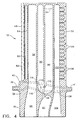
- the blade 30 has an internal cooling configuration that includes a leading edge circuit 52, a mid-chord circuit 54, and a trailing edge circuit 56.
- the leading edge circuit 52 includes first, second, third and fourth radially extending cavities 58, 60, 62 and 64, respectively, formed in the airfoil 42.
- the leading edge circuit 52 further includes a first inlet passage 66 formed through the dovetail 36 and the shank 38.
- the first inlet passage 66 is in fluid communication with the first cavity 58.
- the first and second cavities 58 and 60 are separated by a first rib 68, which has a first plurality of cross-over holes 70 formed therein.
- the third cavity 62 (which is located adjacent to the leading edge 48) is separated from the second cavity 60 by a second rib 72, and the fourth cavity 64 is separated from the third cavity 62 by a third rib 74.
- a second plurality of cross-over holes 76 is formed in the second rib 72, and a third plurality of cross-over holes 78 is formed in the third rib 74.
- the first cavity 58 receives a coolant (usually a portion of the relatively cool compressed air bled from the compressor) through the first inlet passage 66, and the coolant travels radially outwardly through the first cavity 58.
- a coolant usually a portion of the relatively cool compressed air bled from the compressor
- the coolant travels radially outwardly through the first cavity 58.
- the coolant passes into the second cavity 60 through the first cross-over holes 70 and impinges on the inner surface of the pressure side airfoil wall 80 for cooling thereof.
- the coolant then passes through the second cross-over holes 76 into the third cavity 62.
- Some of the coolant in the third cavity 62 passes into the fourth cavity 64 through the third cross-over holes 78 and the remaining coolant exits the third cavity 62, and the airfoil 42, through a number of film cooling holes 82 that are in fluid communication with the third cavity 62.
- the coolant in the fourth cavity 64 exits the airfoil 42 through additional film cooling holes 84 that are in fluid communication with the fourth cavity 64.
- the mid-chord circuit 54 includes fifth, sixth and seventh radially extending cavities 86, 88 and 90, respectively, that are fluidly connected in series in a serpentine arrangement.
- the fifth cavity 86 receives coolant from a second inlet passage 92 formed through the dovetail 36 and the shank 38.
- the coolant travels radially outwardly through the fifth cavity 86, passes into the sixth cavity 88 at an outer turn 94 and then flows radially inwardly through the sixth cavity 88. From there, a portion of the coolant passes into the seventh cavity 90 at an inner turn 96 and again flows radially outwardly.
- the coolant in the seventh cavity 90 passes into the second cavity 60 through a fourth plurality of cross-over holes 98 that are formed in a fourth rib 100, which separates the second cavity 60 and the seventh cavity 90.
- the coolant passing through the fourth cross-over holes 98 also impinges on the inner surface of the pressure side airfoil wall 80 for additional cooling thereof.
- the trailing edge circuit 56 includes an eighth radially extending cavity 102 that receives coolant from a third inlet passage 104 formed through the dovetail 36 and the shank 38. This coolant travels radially outwardly through the eighth cavity 102 and exits the airfoil 42 through trailing edge slots 106 that extend from the eighth cavity 102 to the trailing edge 50.
- the blade's internal cooling configuration as described thus far, is being used as an example to facilitate disclosure of the present invention.
- inventive concept of the present invention is not limited to turbine blades having the three cooling circuits 52,54,56 described above. Indeed, the present invention is applicable to a wide variety of cooling configurations.
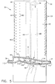
- the present invention cools the platform 40 as well as the airfoil 42.
- the platform 40 is hollow so as to define an internal cooling cavity 108 therein.
- the platform cavity 108 extends substantially the entire axial length (i.e., from the forward angel wing 39 to the aft angel wing 41) of the platform 40 as well as substantially the entire circumferential width of the platform 40.
- Coolant is delivered to the platform cavity 108 via two supply passages 110 that extend between the platform cavity 108 and the inner turn 96 of the mid-chord circuit 54.
- the two supply passages 110 extend substantially laterally from respective sides of the mid-chord circuit 54 so as to supply coolant to both sides of the platform cavity 108.
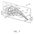
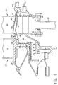
- FIG. 7 and 8 An alternative embodiment of the blade 30 is shown in Figures 7 and 8 .
- the supply passages 110 extend between the platform cavity 108 and the fifth cavity 86.
- the passages 110 connect to the fifth cavity 86 at or near its intersection with the second inlet passage 92, which intersection is the inlet of the mid-chord circuit 54.
- some of the coolant entering into the fifth cavity 86 is diverted into the platform cavity 108 through the supply passages 110.
- This arrangement differs from the aforementioned embodiment of Figures 5 and 6 in that fresh coolant is delivered to the platform cavity 108 rather than coolant that has been used in cooling the airfoil 42.
- the two supply passages 110 extend substantially laterally from respective sides of the mid-chord circuit 54 so as to supply coolant to both sides of the platform cavity 108.
- Other possible alternatives include supply passages that feed coolant from the leading edge circuit 52 and/or the trailing edge circuit 56.
- a plurality of discrete outlet holes 112 is formed in the distal edge of each of the platform angel wings 39 and 41 so as to provide fore and aft egress for the coolant from the platform cavity 108.
- the platform 40 is cooled by coolant entering the platform cavity 108 at the supply passages 110, flowing forward and aft through the platform cavity 108, and exiting the platform 40 via the outlet holes 112.
- the outlet holes 112 are angled away from the direction of rotation of the rotor disk 32. This way, the stream of coolant exiting the outlet holes 112 will add some momentum to the turbine rotor 22.
- film cooling holes 113 are formed in the radially outer surface of the platform 40 (i.e., the platform surface facing the hot gas stream).
- the film cooling holes 113 are generally located at locations on the platform 40 requiring film cooling and are slanted with respect to the outer platform surface so that coolant from the platform cavity 108 passing through the holes 113 will form a thin cooling film on the outer platform surface. It should be noted that, depending on the requirements of a particular application, the blade 30 can be provided with both the outlet holes 112 and the film cooling holes 113 (as shown in the Figures), just outlet holes 112, or just film cooling holes 113.
- Convective cooling enhancement features can be provided in the platform cavity 108 to enhance cooling and reduce the amount of coolant flow needed to cool the platform 40.
- Figure 5 shows an array of radially extending pins 114, commonly referred to as a pin bank, disposed in the platform cavity 108.
- the pins 114 are axially and laterally spaced throughout the platform cavity 108, and each pin 114 extends from the radially outer wall 116 of the platform 40 to the radially inner wall 118.
- Other convective cooling enhancement features such as turbulators or the like could be used as an alternative to the pin bank, but it is noted that by extending between the platform walls 116 and 118, the pins 114 provide structural support to the hollow platform 40.
- the present invention provides other benefits in addition to cooling the platform 40.
- the coolant is expelled from the platform 40 through the outlet holes 112 in the forward angel wing 39 in a series of coolant jets. Because the forward angel wing 39 is radially aligned with inner band 28 the turbine nozzle 20, the coolant jets impinge on the inner band 28.
- positive impingement cooling of the aft end of the inner band 28, which has traditionally been a challenging region to cool is achieved.
- jets of coolant expelled from the platform 40 through the outlet holes 112 in the aft angel wing 41 provide impingement cooling of the second stage or low pressure turbine nozzle inner band 120.
- coolant jets both forward and aft of the turbine rotor 22, act as a blockage or "jet dam" that prevents, or at least reduces, the ingestion of hot gases into the forward and aft disk wheel spaces 122 and 124.
- expelling of coolant into the forward and aft disk wheel spaces 122 and 124 supplements the purging of these spaces, thereby reducing the amount of purge air that would be otherwise required for this purpose.
- the foregoing has described a turbine blade 30 having an internal cooling configuration that includes cooling of the blade platform 40.
- the cooling configuration uses the same coolant to cool a portion of the airfoil 42, to cool the platform 40, to cool the adjoining nozzle inner bands 28 and 120, and to minimize the ingestion of hot gases into the forward and aft disk wheel spaces 122 and 124.
- the present invention thus provides a benefit to the turbine cycle efficiency by reducing the total amount of coolant required for cooling the engine 10.
Landscapes
- Engineering & Computer Science (AREA)
- Mechanical Engineering (AREA)
- General Engineering & Computer Science (AREA)
- Turbine Rotor Nozzle Sealing (AREA)
Claims (7)
- Aube mobile (30) de turbine comportant :une plate-forme (40) dans laquelle est formée une cavité interne (108) ;une pale profilée (42) s'étendant depuis ladite plate-forme (40) ;un circuit de refroidissement interne (54) formé dans ladite pale profilée (42) pour faire circuler dans celui-ci un agent de refroidissement, ledit circuit de refroidissement interne comprenant une pluralité de cavités s'étendant radialement, c'est-à-dire dans le sens longitudinal de la pale, ménagées en série en communication fluidique avec un agencement sinueux, deux desdites cavités radiales étant reliées au niveau d'un tournant ; etau moins un passage d'alimentation (110) s'étendant entre ledit tournant et ladite cavité interne (108) ;ladite aube mobile (30) de turbine comprenant en outre une pluralité de trous (112, 113) formés dans ladite plate-forme (40) de manière à permettre à un agent de refroidissement de sortir de ladite cavité interne (108), et ladite plate-forme (40) comprenant une aile d'ange avant (39) et une aile d'ange arrière (41) ; caractérisée en ce queladite pluralité de trous (112, 113) comprend un premier groupe de trous de sortie (112) formés dans ladite aile d'ange avant (39) et un second groupe de trous de sortie (112) formés dans ladite aile d'ange arrière (41).
- Aube mobile (30) de turbine selon la revendication 1, comportant en outre un second passage d'alimentation (110) s'étendant entre ledit circuit de refroidissement interne (54) et ladite cavité interne (108).
- Aube mobile (30) de turbine selon la revendication 1, dans laquelle lesdits trous de sortie (112) sont obliques dans une direction opposée au sens de rotation dudit disque (32) de rotor.
- Aube mobile (30) de turbine selon la revendication 1, dans laquelle ladite plate-forme (40) comprend une surface radialement, c'est-à-dire dans le sens longitudinal de la pale profilée, extérieure, ladite pluralité de trous (112, 113) comprenant des trous (113) de refroidissement par film formés dans ladite surface radialement extérieure.
- Aube mobile (30) de turbine selon la revendication 1, comportant en outre une pluralité de moyens de renforcement de refroidissement par convection (114) disposés dans ladite cavité interne (108).
- Aube mobile (30) de turbine selon la revendication 5, dans laquelle lesdits moyens de refroidissement par convection (114) comprennent des doigts de refroidissement (114) s'étendant d'une paroi radialement extérieure (116) de ladite plate-forme (40) à une paroi radialement intérieure (118) de ladite plate-forme (40).
- Utilisation d'une aube mobile (30) de turbine dans un moteur (10) à turbine à gaz ayant un disque (32) de rotor de turbine, ladite aube mobile (30) de turbine étant selon l'une quelconque des revendications 1 à 6 et comportant :une queue d'aronde (36) pour monter ladite aube mobile (30) de turbine sur ledit disque (32) de rotor ; etun pied (38) s'étendant depuis ladite queue d'aronde (36), ladite plate-forme (40) étant réunie audit pied (38).
Applications Claiming Priority (2)
| Application Number | Priority Date | Filing Date | Title |
|---|---|---|---|
| US706387 | 1987-01-27 | ||
| US09/706,387 US6402471B1 (en) | 2000-11-03 | 2000-11-03 | Turbine blade for gas turbine engine and method of cooling same |
Publications (3)
| Publication Number | Publication Date |
|---|---|
| EP1205634A2 EP1205634A2 (fr) | 2002-05-15 |
| EP1205634A3 EP1205634A3 (fr) | 2003-10-29 |
| EP1205634B1 true EP1205634B1 (fr) | 2013-01-23 |
Family
ID=24837330
Family Applications (1)
| Application Number | Title | Priority Date | Filing Date |
|---|---|---|---|
| EP01309235A Expired - Lifetime EP1205634B1 (fr) | 2000-11-03 | 2001-10-31 | Aube de turbine et sa utilisation |
Country Status (5)
| Country | Link |
|---|---|
| US (1) | US6402471B1 (fr) |
| EP (1) | EP1205634B1 (fr) |
| JP (1) | JP4138297B2 (fr) |
| BR (1) | BR0105005A (fr) |
| CA (1) | CA2359291A1 (fr) |
Cited By (1)
| Publication number | Priority date | Publication date | Assignee | Title |
|---|---|---|---|---|
| RU2577688C2 (ru) * | 2010-08-30 | 2016-03-20 | Сименс Акциенгезелльшафт | Лопатка для турбомашины и турбомашина, содержащая такую лопатку. |
Families Citing this family (101)
| Publication number | Priority date | Publication date | Assignee | Title |
|---|---|---|---|---|
| GB2365079B (en) * | 2000-07-29 | 2004-09-22 | Rolls Royce Plc | Blade platform cooling |
| EP1207268B1 (fr) * | 2000-11-16 | 2005-02-09 | Siemens Aktiengesellschaft | Aube de turbine à gaz et procédé de fabrication d'une aube de turbine à gaz |
| US6769877B2 (en) | 2002-10-18 | 2004-08-03 | General Electric Company | Undercut leading edge for compressor blades and related method |
| US7121803B2 (en) * | 2002-12-26 | 2006-10-17 | General Electric Company | Compressor blade with dovetail slotted to reduce stress on the airfoil leading edge |
| US6902376B2 (en) * | 2002-12-26 | 2005-06-07 | General Electric Company | Compressor blade with dovetail slotted to reduce stress on the airfoil leading edge |
| JP4016845B2 (ja) * | 2003-02-05 | 2007-12-05 | 株式会社Ihi | ガスタービンエンジン |
| US6955523B2 (en) * | 2003-08-08 | 2005-10-18 | Siemens Westinghouse Power Corporation | Cooling system for a turbine vane |
| US6945749B2 (en) * | 2003-09-12 | 2005-09-20 | Siemens Westinghouse Power Corporation | Turbine blade platform cooling system |
| FR2867223B1 (fr) * | 2004-03-03 | 2006-07-28 | Snecma Moteurs | Turbomachine comme par exemple un turboreacteur pour avion |
| US7104759B2 (en) * | 2004-04-01 | 2006-09-12 | General Electric Company | Compressor blade platform extension and methods of retrofitting blades of different blade angles |
| US7097426B2 (en) * | 2004-04-08 | 2006-08-29 | General Electric Company | Cascade impingement cooled airfoil |
| US7195458B2 (en) * | 2004-07-02 | 2007-03-27 | Siemens Power Generation, Inc. | Impingement cooling system for a turbine blade |
| DE102004037331A1 (de) * | 2004-07-28 | 2006-03-23 | Rolls-Royce Deutschland Ltd & Co Kg | Gasturbinenrotor |
| US7131817B2 (en) * | 2004-07-30 | 2006-11-07 | General Electric Company | Method and apparatus for cooling gas turbine engine rotor blades |
| US7144215B2 (en) * | 2004-07-30 | 2006-12-05 | General Electric Company | Method and apparatus for cooling gas turbine engine rotor blades |
| US7198467B2 (en) * | 2004-07-30 | 2007-04-03 | General Electric Company | Method and apparatus for cooling gas turbine engine rotor blades |
| US20060056968A1 (en) * | 2004-09-15 | 2006-03-16 | General Electric Company | Apparatus and methods for cooling turbine bucket platforms |
| US7413407B2 (en) * | 2005-03-29 | 2008-08-19 | Siemens Power Generation, Inc. | Turbine blade cooling system with bifurcated mid-chord cooling chamber |
| US20060269409A1 (en) * | 2005-05-27 | 2006-11-30 | Mitsubishi Heavy Industries, Ltd. | Gas turbine moving blade having a platform, a method of forming the moving blade, a sealing plate, and a gas turbine having these elements |
| US7467922B2 (en) * | 2005-07-25 | 2008-12-23 | Siemens Aktiengesellschaft | Cooled turbine blade or vane for a gas turbine, and use of a turbine blade or vane of this type |
| US7465152B2 (en) * | 2005-09-16 | 2008-12-16 | General Electric Company | Angel wing seals for turbine blades and methods for selecting stator, rotor and wing seal profiles |
| FR2893974B1 (fr) * | 2005-11-28 | 2011-03-18 | Snecma | Circuit de refroidissement central pour aube mobile de turbomachine |
| US7296973B2 (en) * | 2005-12-05 | 2007-11-20 | General Electric Company | Parallel serpentine cooled blade |
| JP4764219B2 (ja) * | 2006-03-17 | 2011-08-31 | 三菱重工業株式会社 | ガスタービンのシール構造 |
| EP1847696A1 (fr) * | 2006-04-21 | 2007-10-24 | Siemens Aktiengesellschaft | Composant pour un système de post-combustion dans une turbine à gaz et turbine à gaz associée. |
| US7806650B2 (en) * | 2006-08-29 | 2010-10-05 | General Electric Company | Method and apparatus for fabricating a nozzle segment for use with turbine engines |
| US7572102B1 (en) | 2006-09-20 | 2009-08-11 | Florida Turbine Technologies, Inc. | Large tapered air cooled turbine blade |
| US20090003987A1 (en) * | 2006-12-21 | 2009-01-01 | Jack Raul Zausner | Airfoil with improved cooling slot arrangement |
| US7819629B2 (en) * | 2007-02-15 | 2010-10-26 | Siemens Energy, Inc. | Blade for a gas turbine |
| JP5281245B2 (ja) | 2007-02-21 | 2013-09-04 | 三菱重工業株式会社 | ガスタービン動翼のプラットフォーム冷却構造 |
| US7854591B2 (en) * | 2007-05-07 | 2010-12-21 | Siemens Energy, Inc. | Airfoil for a turbine of a gas turbine engine |
| US7845907B2 (en) * | 2007-07-23 | 2010-12-07 | United Technologies Corporation | Blade cooling passage for a turbine engine |
| WO2009016744A1 (fr) * | 2007-07-31 | 2009-02-05 | Mitsubishi Heavy Industries, Ltd. | Pale pour turbine |
| EP2252771A1 (fr) * | 2008-03-07 | 2010-11-24 | ALSTOM Technology Ltd | Pale pour turbine à gaz |
| US8282354B2 (en) * | 2008-04-16 | 2012-10-09 | United Technologies Corporation | Reduced weight blade for a gas turbine engine |
| US20090293495A1 (en) * | 2008-05-29 | 2009-12-03 | General Electric Company | Turbine airfoil with metered cooling cavity |
| US8057178B2 (en) * | 2008-09-04 | 2011-11-15 | General Electric Company | Turbine bucket for a turbomachine and method of reducing bow wave effects at a turbine bucket |
| US8142137B2 (en) * | 2008-11-26 | 2012-03-27 | Alstom Technology Ltd | Cooled gas turbine vane assembly |
| US8292587B2 (en) * | 2008-12-18 | 2012-10-23 | Honeywell International Inc. | Turbine blade assemblies and methods of manufacturing the same |
| GB2467350A (en) * | 2009-02-02 | 2010-08-04 | Rolls Royce Plc | Cooling and sealing in gas turbine engine turbine stage |
| CN101832154B (zh) * | 2009-03-11 | 2013-03-27 | 中国科学院工程热物理研究所 | 一种航空发动机涡轮叶片气膜冷却方法 |
| JP5317014B2 (ja) * | 2009-03-18 | 2013-10-16 | 株式会社Ihi | タービン翼 |
| US8052378B2 (en) * | 2009-03-18 | 2011-11-08 | General Electric Company | Film-cooling augmentation device and turbine airfoil incorporating the same |
| US20100239409A1 (en) * | 2009-03-18 | 2010-09-23 | General Electric Company | Method of Using and Reconstructing a Film-Cooling Augmentation Device for a Turbine Airfoil |
| US8079814B1 (en) * | 2009-04-04 | 2011-12-20 | Florida Turbine Technologies, Inc. | Turbine blade with serpentine flow cooling |
| US8133024B1 (en) | 2009-06-23 | 2012-03-13 | Florida Turbine Technologies, Inc. | Turbine blade with root corner cooling |
| US8647064B2 (en) | 2010-08-09 | 2014-02-11 | General Electric Company | Bucket assembly cooling apparatus and method for forming the bucket assembly |
| US9416666B2 (en) * | 2010-09-09 | 2016-08-16 | General Electric Company | Turbine blade platform cooling systems |
| US8814518B2 (en) * | 2010-10-29 | 2014-08-26 | General Electric Company | Apparatus and methods for cooling platform regions of turbine rotor blades |
| US8851845B2 (en) * | 2010-11-17 | 2014-10-07 | General Electric Company | Turbomachine vane and method of cooling a turbomachine vane |
| US8628294B1 (en) * | 2011-05-19 | 2014-01-14 | Florida Turbine Technologies, Inc. | Turbine stator vane with purge air channel |
| US9447691B2 (en) * | 2011-08-22 | 2016-09-20 | General Electric Company | Bucket assembly treating apparatus and method for treating bucket assembly |
| US8882461B2 (en) | 2011-09-12 | 2014-11-11 | Honeywell International Inc. | Gas turbine engines with improved trailing edge cooling arrangements |
| US20130115060A1 (en) * | 2011-11-04 | 2013-05-09 | General Electric Company | Bucket assembly for turbine system |
| US8858160B2 (en) | 2011-11-04 | 2014-10-14 | General Electric Company | Bucket assembly for turbine system |
| US8845289B2 (en) | 2011-11-04 | 2014-09-30 | General Electric Company | Bucket assembly for turbine system |
| US8840370B2 (en) | 2011-11-04 | 2014-09-23 | General Electric Company | Bucket assembly for turbine system |
| US8870525B2 (en) | 2011-11-04 | 2014-10-28 | General Electric Company | Bucket assembly for turbine system |
| US9022735B2 (en) | 2011-11-08 | 2015-05-05 | General Electric Company | Turbomachine component and method of connecting cooling circuits of a turbomachine component |
| US8905714B2 (en) * | 2011-12-30 | 2014-12-09 | General Electric Company | Turbine rotor blade platform cooling |
| US20130170983A1 (en) * | 2012-01-04 | 2013-07-04 | General Electric Company | Turbine assembly and method for reducing fluid flow between turbine components |
| JP5990639B2 (ja) * | 2012-05-08 | 2016-09-14 | シーメンス アクティエンゲゼルシャフト | ガスタービンの軸ローター部分 |
| US9175565B2 (en) * | 2012-08-03 | 2015-11-03 | General Electric Company | Systems and apparatus relating to seals for turbine engines |
| US9810070B2 (en) * | 2013-05-15 | 2017-11-07 | General Electric Company | Turbine rotor blade for a turbine section of a gas turbine |
| US10184354B2 (en) | 2013-06-19 | 2019-01-22 | United Technologies Corporation | Windback heat shield |
| US20150041590A1 (en) * | 2013-08-09 | 2015-02-12 | General Electric Company | Airfoil with a trailing edge supplement structure |
| US9528377B2 (en) * | 2013-08-21 | 2016-12-27 | General Electric Company | Method and system for cooling rotor blade angelwings |
| WO2015057310A2 (fr) * | 2013-09-17 | 2015-04-23 | United Technologies Corporation | Noyau de refroidissement de plate-forme pour aube de rotor de turbine à gaz |
| EP3047106B1 (fr) * | 2013-09-19 | 2020-09-02 | United Technologies Corporation | Profil aérodynamique de moteur à turbine à gaz comportant un passage de refroidissement de plate-forme alimenté par un serpentin |
| GB201322668D0 (en) * | 2013-12-20 | 2014-02-05 | Rolls Royce Deutschland & Co Kg | Vibration Damper |
| EP2937511B1 (fr) | 2014-04-23 | 2022-06-01 | Raytheon Technologies Corporation | Configuration de passage de refroidissement de profil aérodynamique de turbine à gaz |
| US9803500B2 (en) | 2014-05-05 | 2017-10-31 | United Technologies Corporation | Gas turbine engine airfoil cooling passage configuration |
| US9810072B2 (en) | 2014-05-28 | 2017-11-07 | General Electric Company | Rotor blade cooling |
| US20160153282A1 (en) * | 2014-07-11 | 2016-06-02 | United Technologies Corporation | Stress Reduction For Film Cooled Gas Turbine Engine Component |
| US9982542B2 (en) | 2014-07-21 | 2018-05-29 | United Technologies Corporation | Airfoil platform impingement cooling holes |
| US10465523B2 (en) * | 2014-10-17 | 2019-11-05 | United Technologies Corporation | Gas turbine component with platform cooling |
| US10247011B2 (en) | 2014-12-15 | 2019-04-02 | United Technologies Corporation | Gas turbine engine component with increased cooling capacity |
| WO2016122478A1 (fr) * | 2015-01-28 | 2016-08-04 | Siemens Energy, Inc. | Système de refroidissement de profil de turbine avec refroidissement de profil de plate-forme intégré |
| US10030523B2 (en) * | 2015-02-13 | 2018-07-24 | United Technologies Corporation | Article having cooling passage with undulating profile |
| FR3034129B1 (fr) * | 2015-03-27 | 2019-05-17 | Safran Aircraft Engines | Aube mobile de turbine a conception amelioree pour turbomachine d'aeronef |
| US10030526B2 (en) * | 2015-12-21 | 2018-07-24 | General Electric Company | Platform core feed for a multi-wall blade |
| US10240461B2 (en) | 2016-01-08 | 2019-03-26 | General Electric Company | Stator rim for a turbine engine |
| EP3232000A1 (fr) | 2016-04-15 | 2017-10-18 | Siemens Aktiengesellschaft | Plateforme d'une aube comprenant des trous de refroidissement a film et turbomachine associée |
| US10539026B2 (en) | 2017-09-21 | 2020-01-21 | United Technologies Corporation | Gas turbine engine component with cooling holes having variable roughness |
| US10890074B2 (en) * | 2018-05-01 | 2021-01-12 | Raytheon Technologies Corporation | Coriolis optimized u-channel with platform core |
| DE102018207873A1 (de) * | 2018-05-18 | 2019-11-21 | MTU Aero Engines AG | Laufschaufel für eine Strömungsmaschine |
| US10787932B2 (en) * | 2018-07-13 | 2020-09-29 | Honeywell International Inc. | Turbine blade with dust tolerant cooling system |
| US11174736B2 (en) | 2018-12-18 | 2021-11-16 | General Electric Company | Method of forming an additively manufactured component |
| US11566527B2 (en) | 2018-12-18 | 2023-01-31 | General Electric Company | Turbine engine airfoil and method of cooling |
| US10767492B2 (en) | 2018-12-18 | 2020-09-08 | General Electric Company | Turbine engine airfoil |
| US11499433B2 (en) | 2018-12-18 | 2022-11-15 | General Electric Company | Turbine engine component and method of cooling |
| US11352889B2 (en) | 2018-12-18 | 2022-06-07 | General Electric Company | Airfoil tip rail and method of cooling |
| US10996140B2 (en) * | 2019-03-08 | 2021-05-04 | Rolls-Royce Corporation | Gas turbine engine probes and methods of detecting an engine condition |
| US10844728B2 (en) | 2019-04-17 | 2020-11-24 | General Electric Company | Turbine engine airfoil with a trailing edge |
| US11136890B1 (en) * | 2020-03-25 | 2021-10-05 | General Electric Company | Cooling circuit for a turbomachine component |
| US11506061B2 (en) * | 2020-08-14 | 2022-11-22 | Mechanical Dynamics & Analysis Llc | Ram air turbine blade platform cooling |
| CN112177685A (zh) * | 2020-10-21 | 2021-01-05 | 中国航发沈阳发动机研究所 | 一种高压涡轮转子叶片尾缝冷却结构 |
| CN114320488A (zh) * | 2021-10-20 | 2022-04-12 | 中国航发四川燃气涡轮研究院 | 航空发动机涡轮导向器叶片缘板的封严结构 |
| CN114109517A (zh) * | 2021-11-19 | 2022-03-01 | 华能国际电力股份有限公司 | 一种透平叶片伸出翼冷却和密封结构 |
| CA3182646A1 (fr) * | 2021-12-24 | 2023-06-24 | Itp Next Generation Turbines, S.L. | Configuration de turbine comprenant un agencement d'aube de stator de sortie de turbine |
| JP7436725B1 (ja) | 2023-03-23 | 2024-02-22 | 三菱重工業株式会社 | 動翼、及びこれを備えているガスタービン |
Family Cites Families (14)
| Publication number | Priority date | Publication date | Assignee | Title |
|---|---|---|---|---|
| GB1350471A (en) | 1971-05-06 | 1974-04-18 | Secr Defence | Gas turbine engine |
| GB1553701A (en) * | 1976-05-14 | 1979-09-26 | Rolls Royce | Nozzle guide vane for a gas turbine engine |
| JPS5540221A (en) * | 1978-09-14 | 1980-03-21 | Hitachi Ltd | Cooling structure of gas turbin blade |
| DE3736836A1 (de) * | 1987-10-30 | 1989-05-11 | Bbc Brown Boveri & Cie | Axial durchstroemte gasturbine |
| US4800469A (en) * | 1987-11-23 | 1989-01-24 | Leon Thomas B | Wheel mounted safety light |
| JPH0211801A (ja) * | 1988-06-29 | 1990-01-16 | Hitachi Ltd | ガスタービン冷却動翼 |
| US5197852A (en) * | 1990-05-31 | 1993-03-30 | General Electric Company | Nozzle band overhang cooling |
| US5813835A (en) * | 1991-08-19 | 1998-09-29 | The United States Of America As Represented By The Secretary Of The Air Force | Air-cooled turbine blade |
| EP0875665A3 (fr) * | 1994-11-10 | 1999-02-24 | Westinghouse Electric Corporation | Aube fixe de turbine à gaz avec anneau refroidi |
| US5738489A (en) | 1997-01-03 | 1998-04-14 | General Electric Company | Cooled turbine blade platform |
| JP3758792B2 (ja) * | 1997-02-25 | 2006-03-22 | 三菱重工業株式会社 | ガスタービン動翼のプラットフォーム冷却機構 |
| JP3457831B2 (ja) * | 1997-03-17 | 2003-10-20 | 三菱重工業株式会社 | ガスタービン動翼の冷却プラットフォーム |
| CA2262064C (fr) * | 1998-02-23 | 2002-09-03 | Mitsubishi Heavy Industries, Ltd. | Plate-forme d'aubes mobiles de turbine a gaz |
| CA2231988C (fr) * | 1998-03-12 | 2002-05-28 | Mitsubishi Heavy Industries, Ltd. | Pale de turbine a gaz |
-
2000
- 2000-11-03 US US09/706,387 patent/US6402471B1/en not_active Expired - Lifetime
-
2001
- 2001-10-18 CA CA002359291A patent/CA2359291A1/fr not_active Abandoned
- 2001-10-31 EP EP01309235A patent/EP1205634B1/fr not_active Expired - Lifetime
- 2001-11-01 BR BR0105005-2A patent/BR0105005A/pt not_active IP Right Cessation
- 2001-11-02 JP JP2001337235A patent/JP4138297B2/ja not_active Expired - Fee Related
Cited By (1)
| Publication number | Priority date | Publication date | Assignee | Title |
|---|---|---|---|---|
| RU2577688C2 (ru) * | 2010-08-30 | 2016-03-20 | Сименс Акциенгезелльшафт | Лопатка для турбомашины и турбомашина, содержащая такую лопатку. |
Also Published As
| Publication number | Publication date |
|---|---|
| JP4138297B2 (ja) | 2008-08-27 |
| CA2359291A1 (fr) | 2002-05-03 |
| BR0105005A (pt) | 2002-06-25 |
| EP1205634A3 (fr) | 2003-10-29 |
| JP2002201906A (ja) | 2002-07-19 |
| EP1205634A2 (fr) | 2002-05-15 |
| US6402471B1 (en) | 2002-06-11 |
Similar Documents
| Publication | Publication Date | Title |
|---|---|---|
| EP1205634B1 (fr) | Aube de turbine et sa utilisation | |
| EP1205636B1 (fr) | Aube de turbine à gaz et procédé de refroidissement d'une telle aube | |
| US6960060B2 (en) | Dual coolant turbine blade | |
| US8172533B2 (en) | Turbine blade internal cooling configuration | |
| US6422819B1 (en) | Cooled airfoil for gas turbine engine and method of making the same | |
| EP1001137B1 (fr) | Aube de turbine à gaz à circuits de refroidissement en serpentin | |
| US6609884B2 (en) | Cooling of gas turbine engine aerofoils | |
| US6341939B1 (en) | Tandem cooling turbine blade | |
| US6554563B2 (en) | Tangential flow baffle | |
| US8177507B2 (en) | Triangular serpentine cooling channels | |
| US7458778B1 (en) | Turbine airfoil with a bifurcated counter flow serpentine path | |
| JP6661702B2 (ja) | 先端部レールの冷却を備える翼形部 | |
| US6382908B1 (en) | Nozzle fillet backside cooling | |
| CA2398502C (fr) | Profil de turbine pour turbomoteur a gas | |
| EP3415719B1 (fr) | Structure de refroidissement d'aube de turbomachine | |
| WO2009148655A2 (fr) | Profil aérodynamique de turbine avec cavité de refroidissement dosé | |
| EP2631431B1 (fr) | Agencement de refroidissement de surface portante |
Legal Events
| Date | Code | Title | Description |
|---|---|---|---|
| PUAI | Public reference made under article 153(3) epc to a published international application that has entered the european phase |
Free format text: ORIGINAL CODE: 0009012 |
|
| AK | Designated contracting states |
Kind code of ref document: A2 Designated state(s): AT BE CH CY DE DK ES FI FR GB GR IE IT LI LU MC NL PT SE TR |
|
| AX | Request for extension of the european patent |
Free format text: AL;LT;LV;MK;RO;SI |
|
| PUAL | Search report despatched |
Free format text: ORIGINAL CODE: 0009013 |
|
| AK | Designated contracting states |
Kind code of ref document: A3 Designated state(s): AT BE CH CY DE DK ES FI FR GB GR IE IT LI LU MC NL PT SE TR |
|
| AX | Request for extension of the european patent |
Extension state: AL LT LV MK RO SI |
|
| 17P | Request for examination filed |
Effective date: 20040429 |
|
| AKX | Designation fees paid |
Designated state(s): DE FR GB IT |
|
| 17Q | First examination report despatched |
Effective date: 20040702 |
|
| REG | Reference to a national code |
Ref country code: DE Ref legal event code: R079 Ref document number: 60147619 Country of ref document: DE Free format text: PREVIOUS MAIN CLASS: F01D0005180000 Ipc: F01D0005080000 |
|
| RIC1 | Information provided on ipc code assigned before grant |
Ipc: F01D 5/18 20060101ALI20120518BHEP Ipc: F01D 5/08 20060101AFI20120518BHEP |
|
| GRAP | Despatch of communication of intention to grant a patent |
Free format text: ORIGINAL CODE: EPIDOSNIGR1 |
|
| GRAS | Grant fee paid |
Free format text: ORIGINAL CODE: EPIDOSNIGR3 |
|
| GRAA | (expected) grant |
Free format text: ORIGINAL CODE: 0009210 |
|
| AK | Designated contracting states |
Kind code of ref document: B1 Designated state(s): DE FR GB IT |
|
| REG | Reference to a national code |
Ref country code: GB Ref legal event code: FG4D |
|
| REG | Reference to a national code |
Ref country code: DE Ref legal event code: R096 Ref document number: 60147619 Country of ref document: DE Effective date: 20130321 |
|
| PLBE | No opposition filed within time limit |
Free format text: ORIGINAL CODE: 0009261 |
|
| STAA | Information on the status of an ep patent application or granted ep patent |
Free format text: STATUS: NO OPPOSITION FILED WITHIN TIME LIMIT |
|
| 26N | No opposition filed |
Effective date: 20131024 |
|
| REG | Reference to a national code |
Ref country code: DE Ref legal event code: R097 Ref document number: 60147619 Country of ref document: DE Effective date: 20131024 |
|
| REG | Reference to a national code |
Ref country code: FR Ref legal event code: PLFP Year of fee payment: 15 |
|
| PGFP | Annual fee paid to national office [announced via postgrant information from national office to epo] |
Ref country code: IT Payment date: 20151026 Year of fee payment: 15 Ref country code: DE Payment date: 20151028 Year of fee payment: 15 Ref country code: GB Payment date: 20151027 Year of fee payment: 15 |
|
| PGFP | Annual fee paid to national office [announced via postgrant information from national office to epo] |
Ref country code: FR Payment date: 20151019 Year of fee payment: 15 |
|
| REG | Reference to a national code |
Ref country code: DE Ref legal event code: R119 Ref document number: 60147619 Country of ref document: DE |
|
| GBPC | Gb: european patent ceased through non-payment of renewal fee |
Effective date: 20161031 |
|
| REG | Reference to a national code |
Ref country code: FR Ref legal event code: ST Effective date: 20170630 |
|
| PG25 | Lapsed in a contracting state [announced via postgrant information from national office to epo] |
Ref country code: FR Free format text: LAPSE BECAUSE OF NON-PAYMENT OF DUE FEES Effective date: 20161102 Ref country code: DE Free format text: LAPSE BECAUSE OF NON-PAYMENT OF DUE FEES Effective date: 20170503 Ref country code: GB Free format text: LAPSE BECAUSE OF NON-PAYMENT OF DUE FEES Effective date: 20161031 |
|
| PG25 | Lapsed in a contracting state [announced via postgrant information from national office to epo] |
Ref country code: IT Free format text: LAPSE BECAUSE OF NON-PAYMENT OF DUE FEES Effective date: 20161031 |