EP1205384B1 - Bout d'aile du type grille - Google Patents
Bout d'aile du type grille Download PDFInfo
- Publication number
- EP1205384B1 EP1205384B1 EP01810916A EP01810916A EP1205384B1 EP 1205384 B1 EP1205384 B1 EP 1205384B1 EP 01810916 A EP01810916 A EP 01810916A EP 01810916 A EP01810916 A EP 01810916A EP 1205384 B1 EP1205384 B1 EP 1205384B1
- Authority
- EP
- European Patent Office
- Prior art keywords
- wing
- winglets
- grid
- angle
- main
- Prior art date
- Legal status (The legal status is an assumption and is not a legal conclusion. Google has not performed a legal analysis and makes no representation as to the accuracy of the status listed.)
- Expired - Lifetime
Links
Images


Classifications
-
- B—PERFORMING OPERATIONS; TRANSPORTING
- B64—AIRCRAFT; AVIATION; COSMONAUTICS
- B64C—AEROPLANES; HELICOPTERS
- B64C23/00—Influencing air flow over aircraft surfaces, not otherwise provided for
- B64C23/06—Influencing air flow over aircraft surfaces, not otherwise provided for by generating vortices
- B64C23/065—Influencing air flow over aircraft surfaces, not otherwise provided for by generating vortices at the wing tips
- B64C23/069—Influencing air flow over aircraft surfaces, not otherwise provided for by generating vortices at the wing tips using one or more wing tip airfoil devices, e.g. winglets, splines, wing tip fences or raked wingtips
-
- Y—GENERAL TAGGING OF NEW TECHNOLOGICAL DEVELOPMENTS; GENERAL TAGGING OF CROSS-SECTIONAL TECHNOLOGIES SPANNING OVER SEVERAL SECTIONS OF THE IPC; TECHNICAL SUBJECTS COVERED BY FORMER USPC CROSS-REFERENCE ART COLLECTIONS [XRACs] AND DIGESTS
- Y02—TECHNOLOGIES OR APPLICATIONS FOR MITIGATION OR ADAPTATION AGAINST CLIMATE CHANGE
- Y02T—CLIMATE CHANGE MITIGATION TECHNOLOGIES RELATED TO TRANSPORTATION
- Y02T50/00—Aeronautics or air transport
- Y02T50/10—Drag reduction
Definitions
- the invention relates to a wing according to the preamble of the independent claim.
- the wing has a main wing part with a closed flow around the surface on which main wing part at its outer end one of a wing grid carries existing end section.
- the wing is preferably the wing of a Missile. It can also be the wing of a propeller, the sail a boat or act around the sword of a boat.
- the resistance-reducing effect is in Design point maximum. Should this maximum effect for a different angle or a different speed can be achieved, the grid must be correspondingly be adjusted, for example by adjusting the angle of attack the individual wings or constructive by the change of the Chord lengths of the wings. In the publications mentioned above it is recommended the grid with changes in the angle of attack against the flow as Whole to track, with the lattice parameters remain unchanged.
- a wing with sweep as he applied for high subsonic velocities is used to reduce the induced resistance with a terminal diegelgitter is provided according to the publications mentioned above, the sweep not only the main wing but also the wing grid as a function of the angle of attack and adjust the profile thickness to a given Machiere. This may result in different variations for the main wing and for the wing grid Arrow angle. It now turns out that one designed for the same arrow angle Grid at different sweep angles of main wing and grid one of Main wing part generates different buoyancy and therefore a smaller one usually Has resistance-reducing effect, if it does not change accordingly or adjusted accordingly.
- the invention is now the task of a wing with a main wing part and a resistance reducing at the main wing part terminally arranged To create wing grids, for which wing the drag-reducing effect the wing lattice is fully preserved in changes in the angle of attack, without that set the grid for a current angle or tracked must become.
- main wing part and wing grille of the According to the invention wing the above conditions for overlap and Graduation angle fulfill as well as the condition of the same buoyancy (CL) in the Design point.
- main wing part and wing grille but also have one essentially the same buoyancy gradient ( ⁇ CL / ⁇ or buoyancy change per Change in the angle of attack ⁇ ).
- buoyancy and buoyancy gradient can be met simultaneously when the mean zero flow direction the wing of the wing grid substantially with the zero flow direction of the main wing and if the chord length of the lattice is dependent adapted to the overlap of the wings to the chord length of the main wing part is, such that the ratio of the chord length of the main wing part to chord length of the grid is substantially the same size as that for the average overlap the wing valid Betz'sche correction factor Kappa (see Figure 3).
- main wing part and wing grid In accordance with the zero flow direction of main wing part and wing grid is to be understood that the grid is arranged on the main wing that in an employment of the main wing part relative to a flow such that no buoyancy results (zero attack angle), even the grid generates no buoyancy.
- Below the chord length of the grid is the distance between the leading edge of the foremost wing in the direction of flow to the trailing edge of the in flow direction to understand the last winglet.
- the average overlap is the ratio of mean chord length of the wings and middle grid pitch.
- the buoyancy for main wing part and wing grid is independent of Angle of attack always the same, that also means that the wing grid its resistance-reducing Retains effect regardless of the angle of attack. This is on it due to the fact that in such a wing both wing parts have the same deflection characteristics have, which increases the buoyancy with a change in the angle of attack for main wing and wing grid alike (same buoyancy gradient).
- a resistance-reducing, terminal wing grid for a given main wing part with a predetermined profile and thereby predetermined Buoyancy and given buoyancy gradients, for example, the Cross section of a lattice with at least two wings and an overlap ⁇ 1 so affine magnified that the chord length of the lattice in the above-mentioned type adapted to the chord length of the main wing part.
- This customized grid will arranged on the main wing part such that the stagger angle is greater than that Incident angle of the main wing part in the design point and the employment of the wings is for the compliance of the zero flow of main wing part and Grid adapted.
- the grid is further advantageously arranged on the main wing part such that its center of lift lies on the elastic torsion axis of the main wing part. This is achieved by a positioning corresponding to the buoyancy center of gravity of the sash of the lattice on the main wing.
- the position of the lift center the grid also for a given positioning on the main wing part can be adjusted by adjusting the buoyancy distribution in the grid accordingly or by adjusting the grid accordingly (for Mach numbers only) 0.5).
- the swept is, corresponds to the ratio of the chord length of the main wing part to chord length of the grating multiplied by the above-mentioned Betz correction factor Kappa with the inverse ratio of the cosine the sweep angle.
- the ratio of the chord length of the main wing part to the chord length of the wing lattice differs advantageously from those required in the previous sections Sizes less than 10%.
- the match of the zero flow direction is advantageously better than 2 °.
- Figures 1 and 2 show from the bird's eye two wings according to the publications mentioned above, which has a main wing part 1 and a terminal, drag-reducing wing grid with at least two wings 2 (Figure 1: three wings, Figure 2: three wings), wherein the wings 2 are arranged in parallel staggered and the span of the main wing part 1 is greater than the span of the wing grid.
- the main wing part 1 has at its outer end a in the plane of the direction of flow v arranged wall or intermediate plate 3, on which the wings 2 are mounted.
- the outer ends of the wings 2 are held in a holding frame or end plate 4 ( Figure 2).
- the main wing part 1 has at its outer end a chord length c M.
- the wing shown in Figure 1 is not swept.
- the wing shown in Figure 2 is swept, wherein for individual adjustment of main wing part 1 and wing grid to a specific Mach number of the main wing part 1 a sweep angle ⁇ M and the wings 2 of the lattice have a different angle of sweep ⁇ M sweep angle ⁇ W.
- the illustrated wing is designed for a Mach number of 0.9.
- the critical Mach number for the main wing part 1 is 0.7 for the grid 0.65.
- the span of the grid is about 20% of the total span.
- the sweep angle ⁇ M of the main wing part 1 is positive and is about 40 °
- the sweep angle ⁇ W of the wing 2 of the lattice is negative and is about 42 °.
- a negative sweep angle is chosen for the wing lattice to move the center of lift forward and thus to compensate for the effect of a rectangular lift distribution on the position of the lift center (shift of the lift center of gravity of the entire wing system forward).
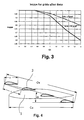
- FIG. 3 shows the correction factor kappa, eg according to A. Betz (coworker of L. Prandtl, see Ing. Archiv, 1932, page 357) for wing lattices with small overlap as a function of the reciprocal value (t / c) of the overlap (c / t ) of the wings and the deflection angle ⁇ (beta), where the overlap is the ratio of the chord lenght c of the lattice lobes to the pitch t (for c and t see Figure 4).
- the graphic is published in: Hut, Des Ing. Taschenbuch, 28. Auflage, page 808, fig. 92.
- FIG. 4 shows, from an exemplary embodiment of the wing according to the invention, the main wing part 1 and the four wings 2 of the resistance-reducing, terminal lattice in section parallel to the wing chords.
- c denotes the chord length of the wings and t the grating pitch.
- c and t are chosen such that c / t (overlap) is smaller than 1. It is not a condition for the wing according to the invention that all wings have equal chord lengths c and that the grid pitch is a regular one. For irregular grids, the conditions given for the mean values of c and t apply.
- the chord c M of the main wing part 1 is smaller by the Betz correction factor than the chord c W of the lattice.
- the stagger angle ⁇ that is to say the angle between the chord c M of the main wing part 1 and the chord c W of the lattice, is greater than the angle of attack of the main wing part 1 in the design point. If the main wing part 1 and the wings 2 of the lattice have the same zero angle of attack, the winglet chords c are on average parallel to the chord c M of the main wing part.
- a regular wing grid as shown in Figure 4, is the buoyancy of the foremost little wing, the buoyancy of the farthest little wing the smallest. It is advantageous to regularly increase the buoyancy on the wings distribute, for example, by the fact that the wings different angles of attack have (from front to back rising, see Figure 6). On the other hand, the grid has with equal angles of attack of the wings the advantage that the position of its Lift center is not dependent on the speed and thereby regardless of the speed on the torsion axis of the main wing part can be.
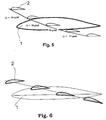
- FIG. 5 shows, in the same manner of representation as FIG. 4, a further exemplary embodiment of the wing according to the invention, in which the buoyancy distribution on the individual wings 2 is taken into account by a staggering angle ⁇ increasing from rear to front.
- the individual stagger angle must be greater than the respective effective angle of attack of the respective wing.
- FIG. 6 shows, in the same manner of representation as FIG. 4, a further, exemplary embodiment of the wing according to the invention, in which the buoyancy distribution over the wings 2 by different angles of incidence of the wings is taken into account.
- the angle of attack of the foremost little wing is smaller than the angle of attack of the farthest little wing.
- the middle wings have medium angles of attack.
- the angles of incidence of the wings are also such that the zero flow direction of the lattice coincides with the zero flow direction of the main wing part 1.
- the wing grid as shown in Figure 6, has a buoyancy center of gravity, whose position is speed-dependent; he shifts with growing Speed to the rear. So if the main focus of lift this Wing grille for a normal speed on the torsion axis of the main wing part is positioned, the wing is at significantly higher speeds nevertheless twisted by the action of the grid and in such a way that the buoyancy reduced, but this can be desirable.
- FIGS. 7 and 8 show two further embodiments of the wing according to the invention in the same way as FIGS. 4 to 6, wherein the foremost wing of the lattice (FIG. 7) or the farthest wing of the lattice (FIG. 8) is arranged on the main wing part 1 such that its pitch angle can be changed in flight and the wing in question can take over the function of an aileron.
- the angle of attack of a small wing is generated by rotation about its axis and / or by means of a curving flap, which is part of the wing profile.
- chord length c Q of the winglet serving as aileron and the grating pitch t Q associated with it are greater than the chord length and grating pitch of the remaining winglets, as a result of which the wing in question can generate more lift.
- the individual stagger angle ⁇ Q of the aileron winglet is so large that the condition for the reduction of the induced resistance is fulfilled even at the maximum deflection of the winglet serving as aileron. In practical terms, this means an additional increase of the individual stagger angle by at least 50% to 100% compared to the stagger angle used without aileron function.
- FIGS. 9 and 10 illustrate further measures which contribute to the further reduction of the resistance of the wing according to the invention and in particular to the plates which limit the wing grid.
- the said plates are already shown in Figures 1 and 2 (intermediate plate 3 and end plate 4).
- FIG. 9 shows an intermediate plate 3 with the profile cross sections of the main wing part 1 and the five wings 2 of a wing grid.
- the intermediate plate 3 is shaped such that its leading edge 10 projects as little as possible over the nose regions 11 of the profiles. This ensures that the boundary layer on the plate surface in the nose region 11 of the profiles is thin.
- suction devices 12 are preferably installed in the plate 3 in the nose regions 11 of the profiles, for example NACA inlets known per se.
- FIG. 10 shows an end plate 4 for the wing grid also shown in FIG. Also in this end plate 4, the leading edge 10 is substantially flush with all nose regions 11 of the profiles of the wings 2 of the wing grid.
Landscapes
- Engineering & Computer Science (AREA)
- Aviation & Aerospace Engineering (AREA)
- Toys (AREA)
- Structures Of Non-Positive Displacement Pumps (AREA)
- Prostheses (AREA)
- Baking, Grill, Roasting (AREA)
- Turbine Rotor Nozzle Sealing (AREA)
Claims (13)
- Aile avec une partie d'aile principale (1) parcourue par un flux et une grille d'aubes réduisant la résistance, disposée à l'extrémité de celle-ci, qui comprend au moins deux ailettes (2) étagées parallèlement, le chevauchement moyen (c/t) des ailettes (2) étant inférieur à 1 et l'angle d'étagement moyen (ω) étant supérieur à l'angle d'incidence de la partie d'aile principale (1) au point d'application, caractérisée en ce que les ailettes (2) sont orientées de telle manière que le sens d'écoulement nul sur les ailettes concorde en moyenne pour l'essentiel avec le sens d'écoulement nul de la partie d'aile principale (1), et en ce que le rapport entre la longueur de corde (cM) de la partie d'aile principale (1) à son extrémité extérieure et la longueur de corde (cw) de la grille d'aubes est sensiblement égal au facteur de correction de Betz kappa valable pour le chevauchement moyen (c/t) des ailettes (2).
- Aile selon la revendication 1, caractérisée en ce que la partie d'aile principale (1) présente un angle de flèche (ϕM) et les ailettes (2) un angle de flèche (ϕW) différent de l'angle de flèche (ϕM) de la partie d'aile principale (1) et en ce que le rapport de la longueur de corde (cM) de la partie d'aile principale (1) à son extrémité extérieure à la longueur de corde (cw) de la grille d'aubes est sensiblement égal au facteur de correction de Betz kappa valable pour le chevauchement moyen (c/t) des ailettes (2) multiplié par le rapport du cosinus de l'angle de flèche (ϕW) des ailettes (2) au cosinus de l'angle de flèche (ϕM) de la partie d'aile principale (1).
- Aile selon l'une des revendications 1 ou 2, caractérisée en ce que la grille d'aubes est disposée sur la partie d'aile principale (1) de telle manière que le centre de portance de la grille d'aubes soit positionné sur l'axe de torsion élastique de la partie d'aile principale (1).
- Aile selon l'une des revendications 1 à 3, caractérisée en ce que les déviations du rapport des deux longueurs de corde (cM, cW) est inférieur à 10 % et que l'imprécision dans la concordance des sens d'écoulement nul est inférieure à 2°.
- Aile selon l'une des revendications 1 à 4, caractérisée en ce que les ailettes (2) sont étagées de l'avant en haut vers l'arrière en bas par rapport au sens d'écoulement.
- Aile selon l'une des revendications 1 à 5, caractérisée en ce que les cordes (c) de toutes les ailettes (2) ont la même longueur, en ce que les cordes (c) de toutes les ailettes sont parallèles entre elles, et en ce que la grille d'aubes présente un quadrillage régulier (t) et un angle d'étagement (ω) régulier.
- Aile selon l'une des revendications 1 à 5, caractérisée en ce que les cordes (c) de toutes les ailettes (2) ont la même longueur, en ce que les cordes (c) de toutes les ailettes sont parallèles entre elles, et en ce que la grille d'aubes présente un quadrillage régulier (t) et en ce que les ailettes (2) présentent des angles d'étagement (ω) croissants de l'arrière vers l'avant.
- Aile selon l'une des revendications 1 à 5, caractérisée en ce que les cordes (c) de toutes les ailettes (2) ont la même longueur, en ce que les ailettes (2) présentent des angles d'étagement (ω) croissants de l'avant vers l'arrière et en ce que la grille d'aubes présente un quadrillage régulier (t).
- Aile selon l'une des revendications 1 à 5, caractérisée en ce que l'ailette (2) de la grille d'aubes, située le plus en avant ou en arrière par rapport au sens d'écoulement présente un angle d'incidence variable en vol pour fonctionner comme un aileron et possède une longueur de corde (cQ) et un quadrillage (tQ) plus grands que les autres ailettes de la grille, et en ce que l'angle d'étagement (ωQ) individuel de l'ailette servant d'aileron est adapté à l'angle d'incidence maximal de cette ailette.
- Aile selon l'une des revendications 1 à 9, caractérisée en ce qu'il est prévu entre la partie d'aile principale (1) et les ailettes (2) de la grille d'aubes une plaque intercalaire (3).
- Aile selon l'une ou l'ensemble des revendications 1 à 10, caractérisée en ce que les extrémités distales des ailettes (2) de la grille d'aubes sont réunies avec une plaque d'extrémité (4).
- Aile selon l'une des revendications 10 ou 11, caractérisée en ce que la plaque intercalaire (3) et/ou la plaque d'extrémité (4) présentent un bord avant (10) qui est sensiblement de niveau avec les zones de bec (11) des profilés de la partie d'aile principale (1) et d'au moins une partie des ailettes (2).
- Aile selon l'une ou l'ensemble des revendications 10 ou 11, caractérisée en ce qu'il est prévu des aspirations dans la plaque intercalaire (3) et/ou la plaque d'extrémité (4) devant les zones de bec (11) d'au moins une partie des ailettes (2).
Applications Claiming Priority (2)
| Application Number | Priority Date | Filing Date | Title |
|---|---|---|---|
| CH21912000 | 2000-11-10 | ||
| CH21912000 | 2000-11-10 |
Publications (3)
| Publication Number | Publication Date |
|---|---|
| EP1205384A2 EP1205384A2 (fr) | 2002-05-15 |
| EP1205384A3 EP1205384A3 (fr) | 2003-12-03 |
| EP1205384B1 true EP1205384B1 (fr) | 2005-04-20 |
Family
ID=4567919
Family Applications (1)
| Application Number | Title | Priority Date | Filing Date |
|---|---|---|---|
| EP01810916A Expired - Lifetime EP1205384B1 (fr) | 2000-11-10 | 2001-09-21 | Bout d'aile du type grille |
Country Status (5)
| Country | Link |
|---|---|
| US (1) | US6431499B1 (fr) |
| EP (1) | EP1205384B1 (fr) |
| AT (1) | ATE293565T1 (fr) |
| CA (1) | CA2357715A1 (fr) |
| DE (1) | DE50105949D1 (fr) |
Families Citing this family (18)
| Publication number | Priority date | Publication date | Assignee | Title |
|---|---|---|---|---|
| US7134631B2 (en) * | 2004-06-10 | 2006-11-14 | Loth John L | Vorticity cancellation at trailing edge for induced drag elimination |
| US7264200B2 (en) * | 2004-07-23 | 2007-09-04 | The Boeing Company | System and method for improved rotor tip performance |
| US20060060696A1 (en) * | 2004-08-26 | 2006-03-23 | Cordy Clifford B Jr | Link between the wing and canard for flutter reduction |
| US7281900B2 (en) * | 2005-05-13 | 2007-10-16 | The Boeing Company | Cascade rotor blade for low noise |
| US20070262205A1 (en) * | 2006-05-09 | 2007-11-15 | Grant Roger H | Retractable multiple winglet |
| US8608441B2 (en) | 2006-06-12 | 2013-12-17 | Energyield Llc | Rotatable blade apparatus with individually adjustable blades |
| ES2338963B1 (es) * | 2008-02-08 | 2011-05-20 | GAMESA INNOVATION & TECHNOLOGY S.L. | Pala multi-punta de aerogenerador. |
| DE102010048266A1 (de) * | 2010-10-12 | 2012-04-12 | Airbus Operations Gmbh | Flügel mit einem Strömungszaun und Flugzeug mit solchen Tragflügeln |
| GB2533413A (en) | 2014-12-19 | 2016-06-22 | Airbus Operations Ltd | Lifting Surfaces |
| EP3269635A1 (fr) | 2016-07-12 | 2018-01-17 | The Aircraft Performance Company UG | Aile d'avion |
| CN110891857B (zh) | 2017-07-12 | 2023-07-11 | 航空器性能公司 | 具有至少两个小翼的飞机机翼 |
| ES2819559T3 (es) * | 2017-12-15 | 2021-04-16 | The Aircraft Performance Company Gmbh | Ala de aeroplano |
| EP3511243B1 (fr) | 2018-01-15 | 2021-12-29 | The Aircraft Performance Company GmbH | Aile d'avion |
| US11011922B2 (en) | 2018-06-09 | 2021-05-18 | Nxp Aeronautics Research, Llc | Monitoring tower with device powered using differentials in electric field strengths within vicinity of powerlines |
| US10391867B1 (en) | 2018-06-09 | 2019-08-27 | Nxp Aeronautics Research, Llc | Apparatus having electric-field actuated generator for powering electrical load within vicinity of powerlines |
| EP4018525A4 (fr) | 2019-08-26 | 2023-09-06 | NXP Aeronautics Research, LLC | Systèmes et appareil de voies aériennes d'uav |
| RU2748824C1 (ru) * | 2020-11-18 | 2021-05-31 | Сергей Николаевич Низов | Законцовка |
| CN112722237B (zh) * | 2021-02-20 | 2023-08-25 | 江西经济管理干部学院 | 一种航空飞行器翼梢小翼 |
Family Cites Families (12)
| Publication number | Priority date | Publication date | Assignee | Title |
|---|---|---|---|---|
| US1466551A (en) * | 1921-12-06 | 1923-08-28 | Bristol Aeroplane Co Ltd | Aircraft, submarine, torpedo, and other totally immersed craft or structure |
| GB196410A (en) * | 1922-02-01 | 1923-04-26 | William Robert Douglas Shaw | Improvements in wings for aerial machines |
| US2743888A (en) * | 1951-10-20 | 1956-05-01 | Collins Radio Co | Variable wing |
| GB846322A (en) * | 1956-08-24 | 1960-08-31 | Commw Of Australia Crown Solic | Lift augmenting means |
| US4595160A (en) * | 1983-05-18 | 1986-06-17 | Jonathan Santos | Wing tip airfoils |
| US4671473A (en) * | 1984-11-08 | 1987-06-09 | Goodson Kenneth W | Airfoil |
| US5312070A (en) * | 1992-04-02 | 1994-05-17 | Grumman Aerospace Corporation | Segmented variable sweep wing aircraft |
| DE59402023D1 (de) | 1993-04-05 | 1997-04-17 | Roche Ulrich | Flügel mit flügelgitter als endabschnitt |
| US5823480A (en) | 1993-04-05 | 1998-10-20 | La Roche; Ulrich | Wing with a wing grid as the end section |
| US5634613A (en) * | 1994-07-18 | 1997-06-03 | Mccarthy; Peter T. | Tip vortex generation technology for creating a lift enhancing and drag reducing upwash effect |
| RU2095281C1 (ru) * | 1996-01-10 | 1997-11-10 | Александр Вячеславович Корнушенко | Концевое крылышко |
| DE19926832B4 (de) * | 1999-06-12 | 2005-09-15 | Airbus Deutschland Gmbh | Unterschallflugzeug vorzugsweise mit gepfeilten Tragflügeln |
-
2001
- 2001-09-21 AT AT01810916T patent/ATE293565T1/de not_active IP Right Cessation
- 2001-09-21 DE DE50105949T patent/DE50105949D1/de not_active Expired - Fee Related
- 2001-09-21 EP EP01810916A patent/EP1205384B1/fr not_active Expired - Lifetime
- 2001-09-25 CA CA002357715A patent/CA2357715A1/fr not_active Abandoned
- 2001-10-12 US US09/976,696 patent/US6431499B1/en not_active Expired - Fee Related
Also Published As
| Publication number | Publication date |
|---|---|
| CA2357715A1 (fr) | 2002-05-10 |
| ATE293565T1 (de) | 2005-05-15 |
| EP1205384A2 (fr) | 2002-05-15 |
| US20020060272A1 (en) | 2002-05-23 |
| US6431499B1 (en) | 2002-08-13 |
| EP1205384A3 (fr) | 2003-12-03 |
| DE50105949D1 (de) | 2005-05-25 |
Similar Documents
| Publication | Publication Date | Title |
|---|---|---|
| EP1205384B1 (fr) | Bout d'aile du type grille | |
| DE2726589C2 (fr) | ||
| EP2420671B1 (fr) | Pale d'éolienne | |
| DE3242584A1 (de) | Anordnung von zusatzflaechen an den spitzen eines tragfluegels | |
| EP1583904A2 (fr) | Pale de rotor concue pour une installation d'energie eolienne | |
| DE10300284A1 (de) | Rotorblatt für eine Windenergieanlage | |
| WO2003104646A1 (fr) | Pale de rotor d'une eolienne | |
| DE1934246A1 (de) | Grenzschichtenkontrolle fuer Fliessabtrennung und Waermeaustausch | |
| DE3025753A1 (de) | Vorrichtung zur regelung von axialverdichtern | |
| DE10307682A1 (de) | Rotorblatt einer Windenergieanlage | |
| DE2728388A1 (de) | Leitwerk fuer ein projektil | |
| WO2001048377A1 (fr) | Pale de rotor pour eolienne | |
| DE102014203442A1 (de) | Rotorblatt einer Windenergieanlage und Windenergieanlage | |
| DE102005018427A1 (de) | Auftriebsfläche mit verbessertem Ablöseverhalten bei stark veränderlichem Anstellwinkel | |
| DE3424010A1 (de) | Schraube fuer gasfoermige oder fluessige medien, insbesondere luftschraube | |
| EP3399183A1 (fr) | Pale de rotor d'une éolienne | |
| WO1996001368A1 (fr) | Convertisseur d'energie eolienne a axe de rotation vertical | |
| EP2976524A1 (fr) | Pale de rotor d'une éolienne, éolienne, et procédé pour faire fonctionner une éolienne | |
| DE3626432C1 (de) | Seitenleitwerk fuer Flugzuge mit spreizbaren Ruderklappen | |
| DE1280058B (de) | Ein- oder Austrittsoeffnung fuer ein Stroemungs-mittel mit jalousieartigen Verschlussfluegeln | |
| DE3909993A1 (de) | Mehrgliedriger fluegel insbesondere als schiffssegel | |
| EP0642440B1 (fr) | Aile comportant une grille comme section terminale | |
| EP3969741B1 (fr) | Pale de rotor et éolienne | |
| DE102010045080B4 (de) | Flügelprofil | |
| EP3553306B1 (fr) | Pale de rotor d'une éolienne pourvue d'un générateur de vortex |
Legal Events
| Date | Code | Title | Description |
|---|---|---|---|
| PUAI | Public reference made under article 153(3) epc to a published international application that has entered the european phase |
Free format text: ORIGINAL CODE: 0009012 |
|
| AK | Designated contracting states |
Kind code of ref document: A2 Designated state(s): AT BE CH CY DE DK ES FI FR GB GR IE IT LI LU MC NL PT SE TR |
|
| AX | Request for extension of the european patent |
Free format text: AL;LT;LV;MK;RO;SI |
|
| PUAL | Search report despatched |
Free format text: ORIGINAL CODE: 0009013 |
|
| RIC1 | Information provided on ipc code assigned before grant |
Ipc: 7B 64C 5/08 A Ipc: 7B 64C 23/06 B |
|
| AK | Designated contracting states |
Kind code of ref document: A3 Designated state(s): AT BE CH CY DE DK ES FI FR GB GR IE IT LI LU MC NL PT SE TR |
|
| AX | Request for extension of the european patent |
Extension state: AL LT LV MK RO SI |
|
| 17P | Request for examination filed |
Effective date: 20040508 |
|
| AKX | Designation fees paid |
Designated state(s): AT BE CH CY DE DK ES FI FR GB GR IE IT LI LU MC NL PT SE TR |
|
| 17Q | First examination report despatched |
Effective date: 20040819 |
|
| GRAP | Despatch of communication of intention to grant a patent |
Free format text: ORIGINAL CODE: EPIDOSNIGR1 |
|
| GRAS | Grant fee paid |
Free format text: ORIGINAL CODE: EPIDOSNIGR3 |
|
| GRAA | (expected) grant |
Free format text: ORIGINAL CODE: 0009210 |
|
| AK | Designated contracting states |
Kind code of ref document: B1 Designated state(s): AT BE CH CY DE DK ES FI FR GB GR IE IT LI LU MC NL PT SE TR |
|
| PG25 | Lapsed in a contracting state [announced via postgrant information from national office to epo] |
Ref country code: IT Free format text: LAPSE BECAUSE OF FAILURE TO SUBMIT A TRANSLATION OF THE DESCRIPTION OR TO PAY THE FEE WITHIN THE PRESCRIBED TIME-LIMIT;WARNING: LAPSES OF ITALIAN PATENTS WITH EFFECTIVE DATE BEFORE 2007 MAY HAVE OCCURRED AT ANY TIME BEFORE 2007. THE CORRECT EFFECTIVE DATE MAY BE DIFFERENT FROM THE ONE RECORDED. Effective date: 20050420 Ref country code: IE Free format text: LAPSE BECAUSE OF FAILURE TO SUBMIT A TRANSLATION OF THE DESCRIPTION OR TO PAY THE FEE WITHIN THE PRESCRIBED TIME-LIMIT Effective date: 20050420 Ref country code: FI Free format text: LAPSE BECAUSE OF FAILURE TO SUBMIT A TRANSLATION OF THE DESCRIPTION OR TO PAY THE FEE WITHIN THE PRESCRIBED TIME-LIMIT Effective date: 20050420 Ref country code: TR Free format text: LAPSE BECAUSE OF FAILURE TO SUBMIT A TRANSLATION OF THE DESCRIPTION OR TO PAY THE FEE WITHIN THE PRESCRIBED TIME-LIMIT Effective date: 20050420 Ref country code: NL Free format text: LAPSE BECAUSE OF FAILURE TO SUBMIT A TRANSLATION OF THE DESCRIPTION OR TO PAY THE FEE WITHIN THE PRESCRIBED TIME-LIMIT Effective date: 20050420 |
|
| REG | Reference to a national code |
Ref country code: GB Ref legal event code: FG4D Free format text: NOT ENGLISH |
|
| REG | Reference to a national code |
Ref country code: CH Ref legal event code: EP |
|
| REG | Reference to a national code |
Ref country code: IE Ref legal event code: FG4D Free format text: LANGUAGE OF EP DOCUMENT: GERMAN |
|
| REF | Corresponds to: |
Ref document number: 50105949 Country of ref document: DE Date of ref document: 20050525 Kind code of ref document: P |
|
| PG25 | Lapsed in a contracting state [announced via postgrant information from national office to epo] |
Ref country code: GR Free format text: LAPSE BECAUSE OF FAILURE TO SUBMIT A TRANSLATION OF THE DESCRIPTION OR TO PAY THE FEE WITHIN THE PRESCRIBED TIME-LIMIT Effective date: 20050720 Ref country code: DK Free format text: LAPSE BECAUSE OF FAILURE TO SUBMIT A TRANSLATION OF THE DESCRIPTION OR TO PAY THE FEE WITHIN THE PRESCRIBED TIME-LIMIT Effective date: 20050720 Ref country code: SE Free format text: LAPSE BECAUSE OF FAILURE TO SUBMIT A TRANSLATION OF THE DESCRIPTION OR TO PAY THE FEE WITHIN THE PRESCRIBED TIME-LIMIT Effective date: 20050720 |
|
| PG25 | Lapsed in a contracting state [announced via postgrant information from national office to epo] |
Ref country code: ES Free format text: LAPSE BECAUSE OF FAILURE TO SUBMIT A TRANSLATION OF THE DESCRIPTION OR TO PAY THE FEE WITHIN THE PRESCRIBED TIME-LIMIT Effective date: 20050731 |
|
| GBT | Gb: translation of ep patent filed (gb section 77(6)(a)/1977) |
Effective date: 20050808 |
|
| PG25 | Lapsed in a contracting state [announced via postgrant information from national office to epo] |
Ref country code: PT Free format text: LAPSE BECAUSE OF FAILURE TO SUBMIT A TRANSLATION OF THE DESCRIPTION OR TO PAY THE FEE WITHIN THE PRESCRIBED TIME-LIMIT Effective date: 20050920 |
|
| PG25 | Lapsed in a contracting state [announced via postgrant information from national office to epo] |
Ref country code: CY Free format text: LAPSE BECAUSE OF FAILURE TO SUBMIT A TRANSLATION OF THE DESCRIPTION OR TO PAY THE FEE WITHIN THE PRESCRIBED TIME-LIMIT Effective date: 20050921 Ref country code: AT Free format text: LAPSE BECAUSE OF NON-PAYMENT OF DUE FEES Effective date: 20050921 |
|
| PG25 | Lapsed in a contracting state [announced via postgrant information from national office to epo] |
Ref country code: MC Free format text: LAPSE BECAUSE OF NON-PAYMENT OF DUE FEES Effective date: 20050930 Ref country code: BE Free format text: LAPSE BECAUSE OF NON-PAYMENT OF DUE FEES Effective date: 20050930 Ref country code: LU Free format text: LAPSE BECAUSE OF NON-PAYMENT OF DUE FEES Effective date: 20050930 Ref country code: CH Free format text: LAPSE BECAUSE OF NON-PAYMENT OF DUE FEES Effective date: 20050930 Ref country code: LI Free format text: LAPSE BECAUSE OF NON-PAYMENT OF DUE FEES Effective date: 20050930 |
|
| NLV1 | Nl: lapsed or annulled due to failure to fulfill the requirements of art. 29p and 29m of the patents act | ||
| REG | Reference to a national code |
Ref country code: IE Ref legal event code: FD4D |
|
| PLBE | No opposition filed within time limit |
Free format text: ORIGINAL CODE: 0009261 |
|
| STAA | Information on the status of an ep patent application or granted ep patent |
Free format text: STATUS: NO OPPOSITION FILED WITHIN TIME LIMIT |
|
| ET | Fr: translation filed | ||
| 26N | No opposition filed |
Effective date: 20060123 |
|
| REG | Reference to a national code |
Ref country code: CH Ref legal event code: PL |
|
| PGFP | Annual fee paid to national office [announced via postgrant information from national office to epo] |
Ref country code: DE Payment date: 20070921 Year of fee payment: 7 |
|
| BERE | Be: lapsed |
Owner name: LA ROCHE, ULRICH Effective date: 20050930 |
|
| PGFP | Annual fee paid to national office [announced via postgrant information from national office to epo] |
Ref country code: GB Payment date: 20070914 Year of fee payment: 7 |
|
| PGFP | Annual fee paid to national office [announced via postgrant information from national office to epo] |
Ref country code: FR Payment date: 20070914 Year of fee payment: 7 |
|
| GBPC | Gb: european patent ceased through non-payment of renewal fee |
Effective date: 20080921 |
|
| REG | Reference to a national code |
Ref country code: FR Ref legal event code: ST Effective date: 20090529 |
|
| PG25 | Lapsed in a contracting state [announced via postgrant information from national office to epo] |
Ref country code: DE Free format text: LAPSE BECAUSE OF NON-PAYMENT OF DUE FEES Effective date: 20090401 |
|
| PG25 | Lapsed in a contracting state [announced via postgrant information from national office to epo] |
Ref country code: FR Free format text: LAPSE BECAUSE OF NON-PAYMENT OF DUE FEES Effective date: 20080930 |
|
| PG25 | Lapsed in a contracting state [announced via postgrant information from national office to epo] |
Ref country code: GB Free format text: LAPSE BECAUSE OF NON-PAYMENT OF DUE FEES Effective date: 20080921 |