EP1205360A1 - Schaltungsanordnung für ein selbstleuchtendes Kennzeichen - Google Patents
Schaltungsanordnung für ein selbstleuchtendes Kennzeichen Download PDFInfo
- Publication number
- EP1205360A1 EP1205360A1 EP01122603A EP01122603A EP1205360A1 EP 1205360 A1 EP1205360 A1 EP 1205360A1 EP 01122603 A EP01122603 A EP 01122603A EP 01122603 A EP01122603 A EP 01122603A EP 1205360 A1 EP1205360 A1 EP 1205360A1
- Authority
- EP
- European Patent Office
- Prior art keywords
- self
- illuminating
- license plate
- circuit arrangement
- number plate
- Prior art date
- Legal status (The legal status is an assumption and is not a legal conclusion. Google has not performed a legal analysis and makes no representation as to the accuracy of the status listed.)
- Granted
Links
- 230000007257 malfunction Effects 0.000 claims abstract description 8
- 238000001514 detection method Methods 0.000 description 7
- 230000002950 deficient Effects 0.000 description 3
- 230000004913 activation Effects 0.000 description 1
- 230000007547 defect Effects 0.000 description 1
- 230000001419 dependent effect Effects 0.000 description 1
- 238000011161 development Methods 0.000 description 1
- 230000018109 developmental process Effects 0.000 description 1
- 230000000694 effects Effects 0.000 description 1
- 230000005684 electric field Effects 0.000 description 1
- 230000003760 hair shine Effects 0.000 description 1
- 238000002372 labelling Methods 0.000 description 1
- 238000005259 measurement Methods 0.000 description 1
- 238000000034 method Methods 0.000 description 1
Images
Classifications
-
- B—PERFORMING OPERATIONS; TRANSPORTING
- B60—VEHICLES IN GENERAL
- B60R—VEHICLES, VEHICLE FITTINGS, OR VEHICLE PARTS, NOT OTHERWISE PROVIDED FOR
- B60R13/00—Elements for body-finishing, identifying, or decorating; Arrangements or adaptations for advertising purposes
- B60R13/10—Registration, licensing, or like devices
-
- B—PERFORMING OPERATIONS; TRANSPORTING
- B60—VEHICLES IN GENERAL
- B60Q—ARRANGEMENT OF SIGNALLING OR LIGHTING DEVICES, THE MOUNTING OR SUPPORTING THEREOF OR CIRCUITS THEREFOR, FOR VEHICLES IN GENERAL
- B60Q1/00—Arrangement of optical signalling or lighting devices, the mounting or supporting thereof or circuits therefor
- B60Q1/26—Arrangement of optical signalling or lighting devices, the mounting or supporting thereof or circuits therefor the devices being primarily intended to indicate the vehicle, or parts thereof, or to give signals, to other traffic
- B60Q1/56—Arrangement of optical signalling or lighting devices, the mounting or supporting thereof or circuits therefor the devices being primarily intended to indicate the vehicle, or parts thereof, or to give signals, to other traffic for illuminating registrations or the like, e.g. for licence plates
Definitions
- the invention relates to a circuit arrangement for a self-illuminating license plate of a motor vehicle according to the preamble of claim 1.
- License plates for motor vehicles are generally known, both of these are attached to the front and rear of a vehicle and a shield surface have with a defining the local registration office of the motor vehicle Marks are provided.
- Conventional license plates have one reflective surface, which makes them legible even in the dark, as usual lighting is assigned to the license plate, through the side, above and / or incandescent lamps arranged below the shield surface.
- the license plate by a in the field of labeling arranged, electrically activatable luminescent film arrangement with at least one partially transparent design of the sign area is illuminated.
- a self-illuminating design of the license plate is a separate one In principle, it is no longer necessary to illuminate the license plate.
- Electroluminescent fluorescent film are used by a ballast with Power is supplied and controlled.
- the one to activate the electroluminescent The film tension depends on the film and is usually between 50 and 150 volts, depending on the electroluminescent effect used an alternating or DC voltage to generate the necessary electrical field in the film is used. This necessary voltage is determined by the ballast from the 12V electrical system voltage generated. Usually, the ballast of the self-illuminating license plate is activated when the motor vehicle light is switched on.
- a disadvantage of today's self-illuminating license plates is that it is on the one hand for the Driver of a motor vehicle is not easily recognizable whether that in operation self-illuminating license plate actually lights up and still not possible is also in a holder for a self-illuminating license plate Use standard license plates.
- the invention is therefore based on the object of a circuit arrangement create that avoids the disadvantages mentioned above
- the circuit arrangement according to the invention for a self-illuminating license plate has a self-illuminating license plate, a control device for controlling the self-illuminating license plate and a device for detecting the Functionality of the self-illuminating license plate.
- the arrangement preferably has an additional license plate light which is switched off when the control unit is functioning properly License plate recognizes, and which is switched on when the control unit Malfunction of the self-illuminating license plate detected.
- the self-illuminating license plate can serve as so-called ambient lighting, in that the control unit of the circuit arrangement is self-illuminating License plate energized when the motor vehicle is unlocked.
- the control unit will measure the functionality of the perform self-illuminating license plate, when unlocking the The additional license plate light is used as a surrounding light, if the control unit detects a malfunction of the self-illuminating number plate.
- Detection of the functionality of the self-illuminating license plate can done electrically or optically in a manner known per se, so that the Control unit receives a detection signal via a detection line, from which to the Functionality of the self-illuminating license plate is closed.
- the Detection signal is preferably in the ballast of the self-illuminating License plate generated and passed to the control unit.
- the circuit arrangement according to the invention advantageously makes it possible to instead of a self-illuminating license plate a conventional license plate use and mount in the appropriate bracket of the motor vehicle, because the control unit then detects a malfunction of the number plate and the additional one Number plate light activated. In this case, the measurement of the Functionality of the license plate while the Motor vehicle or the vehicle lighting set.
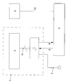
- the figure shows a self-illuminating mark 1, which is an electroluminescent Has film 2 and a ballast 3, the ballast 3 via a predetermined number of cables 6 is connected to the film 2.
- the ballast serves et al to generate the voltage required to operate the film 2 and detected the functionality of the film 2.
- the self-illuminating license plate or its Ballast 3 is connected to a control device 4, the control device 4 self-illuminating license plate 1 or the ballast 3 via a line 8 controls.
- the ballast 3 is connected via a line 7 to the vehicle electrical system voltage provided.
- the circuit arrangement has an additional license plate light 5, which is also connected via a line 10 to the control device 4 and from this is driven or supplied with voltage.
- the additional License plate lamp 5 known lamps are used, for example a Incandescent lamp or corresponding light emitting diodes.
- the additional license plate lamp 5 has a plurality of lamps, for example four, these lamps being all or at least partially dimmable.
- the Ballast 3 detects the functionality of the self-illuminating license plate 1 and outputs a suitable signal to the control unit 4 via a line 9.
- the Functionality detection can also be performed by the control unit, which based on a suitable signal of the ballast 3 on the functionality of the self-illuminating license plate 1 decides and takes appropriate measures. Suitable measuring methods for determining the functionality of the self-illuminating License plates are known.
- the control unit 4 has a malfunction of the self-illuminating license plate 1 detected or recognized, this can have two causes to have.
- the self-illuminating license plate 1 may be defective.
- the number plate can be a standard number plate that is not is self-luminous, act.
- the additional conventional Number plate light 5 switched on, so that the number plate 1 is switched on Vehicle lighting is illuminated.
- a message can also be displayed that the self-illuminating license plate 1 is defective or not available.
- Farther can the voltage supplied via line 7 of the self-illuminating license plate 1 can be switched off to avoid potential voltage losses and thus an unnecessary Avoid stressing the electrical system.
- the self-illuminating indicator 1 can be used as the ambient light of the motor vehicle, for example when using the motor vehicle key a locked motor vehicle is unlocked because in In this case, a certain amount for orienting the motor vehicle owner in the dark Exterior lighting of the motor vehicle is switched on for a predetermined period of time becomes.
- the self-illuminating license plate 1 as the ambient light of the Motor vehicle is also the functionality of the control unit 4 self-luminous indicator 1 determines.
- the control unit 4 detects a malfunction of the self-illuminating license plate 1 and on the part of the control unit 4 Illuminant of the additional conventional license plate lamp 5 as Ambient lighting controlled and used, some or all of the Bulbs of the additional license plate lamp 5 are dimmed high.
- the detection of the functionality of the self-illuminating license plate 1 can be found in predetermined time intervals or continuously, so that the control unit 4 at certain intervals or continuously via the functionality of the self-illuminating license plate 1 is informed and in the event of a defect in the self-illuminating license plate 1 immediately or within a short time an emergency operation activated via the additional license plate light 5.
Landscapes
- Engineering & Computer Science (AREA)
- Mechanical Engineering (AREA)
- Lighting Device Outwards From Vehicle And Optical Signal (AREA)
- Vehicle Waterproofing, Decoration, And Sanitation Devices (AREA)
Abstract
Description
- 1
- selbstleuchtendes Kennzeichen
- 2
- Elektrolumineszenzfolie Steuergerät
- 3
- Vorschaltgerät
- 4
- Steuergerät
- 5
- zusätzliche Kennzeichenleuchte
- 6
- Leitungen
- 7
- Bordnetzspannung
- 8
- Signalpfad Ansteuerung
- 9
- Signalpfad Funktionsfähigkeitssignal
- 10
- Ansteuerung zusätzliche Kennzeichenleuchte
Claims (9)
- Schaltungsanordnung für ein selbstleuchtendes Kennzeichen mit einem selbstleuchtenden Kennzeichen (1) und einem Steuergerät (4), dadurch gekennzeichnet, daß die Schaltungsanordnung eine Vorrichtung (3, 4) zur Detektion der Funktionsfähigkeit des selbstleuchtenden Kennzeichens (1) aufweist.
- Schaltungsanordnung nach Anspruch 1, dadurch gekennzeichnet, daß das Steuergeräts (4) anhand eines Signals des selbstleuchtenden Kennzeichens (1) die Funktionsfähigkeit des selbstleuchtenden Kennzeichens (1) feststellt.
- Schaltungsanordnung nach Anspruch 1 oder 2, dadurch gekennzeichnet, daß die Anordnung eine zusätzliche Kennzeichenleuchte (5) aufweist, die abgeschaltet ist, wenn das Steuergerät (4) die Funktionsfähigkeit des selbstleuchtenden Kennzeichens (1) erkennt, und die eingeschaltet ist, wenn das Steuergerät (4) eine Fehlfunktion des selbstleuchtenden Kennzeichens detektiert.
- Schaltungsanordnung nach einem der vorangegangenen Ansprüche, dadurch gekennzeichnet, daß das Steuergerät (4) das selbstleuchtende Kennzeichen (1) ansteuert, wenn das die Schaltungsanordnung enthaltende Kraftfahrzeug entriegelt wird.
- Schaltungsanordnung nach Anspruch 4, dadurch gekennzeichnet, daß bei der Entriegelung des Kraftfahrzeugs das selbstleuchtende Kennzeichen (1) als Umfeldbeleuchtung bei festgestellter Funktionsfähigkeit des selbstleuchtende Kennzeichens (1) verwendet wird, während die zusätzliche Kennzeichenleuchte (3) dann als Umfeldbeleuchtung zum Einsatz kommt, wenn das Steuergerät eine Fehlfunktion des selbstleuchtenden Kennzeichens detektiert.
- Schaltungsanordnung nach einem der Ansprüche 1 bis 3, dadurch gekennzeichnet, daß das Steuergerät (4) die zusätzliche Kennzeichenleuchte (5) ansteuert, wenn das die Schaltungsanordnung enthaltende Kraftfahrzeug entriegelt wird.
- Schaltungsanordnung nach einem der vorangegangenen Ansprüche, dadurch gekennzeichnet, daß die Detektion der Funktionsfähigkeit des selbstleuchtenden Kennzeichens (1) elektrisch oder optisch erfolgt.
- Schaltungsanordnung nach einem der vorangegangenen Ansprüche, dadurch gekennzeichnet, daß bei eingeschalteter Kraftfahrzeugbeleuchtung die Funktionsfähigkeit des selbstleuchtenden Kennzeichens (1) kontinuierlich detektiert wird.
- Schaltungsanordnung nach einem der Ansprüche 1 bis 7, dadurch gekennzeichnet, daß bei eingeschalteter Kraftfahrzeugbeleuchtung die Funktionsfähigkeit des selbstleuchtenden Kennzeichens (1) in vorgegebenen Zeitintervallen detektiert wird.
Applications Claiming Priority (2)
| Application Number | Priority Date | Filing Date | Title |
|---|---|---|---|
| DE2000155667 DE10055667A1 (de) | 2000-11-10 | 2000-11-10 | Schaltungsanordnung für ein selbstleuchtendes Kennzeichen |
| DE10055667 | 2000-11-10 |
Publications (3)
| Publication Number | Publication Date |
|---|---|
| EP1205360A1 true EP1205360A1 (de) | 2002-05-15 |
| EP1205360B1 EP1205360B1 (de) | 2005-10-26 |
| EP1205360B9 EP1205360B9 (de) | 2007-02-14 |
Family
ID=7662779
Family Applications (1)
| Application Number | Title | Priority Date | Filing Date |
|---|---|---|---|
| EP20010122603 Expired - Lifetime EP1205360B9 (de) | 2000-11-10 | 2001-09-26 | Schaltungsanordnung für ein selbstleuchtendes Kennzeichen |
Country Status (2)
| Country | Link |
|---|---|
| EP (1) | EP1205360B9 (de) |
| DE (2) | DE10055667A1 (de) |
Cited By (1)
| Publication number | Priority date | Publication date | Assignee | Title |
|---|---|---|---|---|
| FR2877294A1 (fr) * | 2004-11-02 | 2006-05-05 | Sebastien Buisine | Plaque d'immatriculation electroluminescente serigraphie |
Families Citing this family (1)
| Publication number | Priority date | Publication date | Assignee | Title |
|---|---|---|---|---|
| DE102005060400B4 (de) * | 2004-07-20 | 2020-12-10 | Volkswagen Ag | Baueinheit für einen Deckel eines Fahrzeugheckbereiches |
Citations (4)
| Publication number | Priority date | Publication date | Assignee | Title |
|---|---|---|---|---|
| GB2227115A (en) * | 1988-12-20 | 1990-07-18 | Hiram James Hey | Trailer registration display |
| EP0976617A1 (de) * | 1998-07-27 | 2000-02-02 | PLASTAL - ZCP S.p.A. | Stützkörper für Beleuchtungslampen von Kraftfahrzeugkennzeichen-Schildern |
| GB2340982A (en) * | 1998-08-28 | 2000-03-01 | Bernard Arthur Henshaw | Vehicle Registration Plate |
| DE20004189U1 (de) * | 2000-03-06 | 2000-05-25 | Kornemann, Klaus, Dr., 60435 Frankfurt | Elektrische Beleuchtung für ein Kfz-Kennzeichen |
Family Cites Families (6)
| Publication number | Priority date | Publication date | Assignee | Title |
|---|---|---|---|---|
| DE3724943C2 (de) * | 1987-07-28 | 1994-08-04 | Reitter & Schefenacker Kg | Leuchteneinrichtung für Kraftfahrzeuge |
| DE4312940A1 (de) * | 1993-02-19 | 1994-08-25 | Anastasios Zavrakis | Kraftfahrzeugbauteil |
| DE29617876U1 (de) * | 1996-10-15 | 1997-01-16 | Herrmann, Ottmar, 97258 Hemmersheim | Kfz-Kennzeichenbeleuchtung |
| DE29712954U1 (de) * | 1997-07-22 | 1997-10-16 | FER Fahrzeugelektrik GmbH, 99817 Eisenach | Kennzeichenschild für ein Kraftfahrzeug |
| DE29906986U1 (de) * | 1999-04-20 | 1999-07-01 | Outdoor Bike Trades GmbH, 50677 Köln | Beleuchtung von Nummerschildrahmen mittels El-Lichtfolie zum Einschieben in Nummernschildrahmengehäuse und dazugehörendem extern untergebrachten Inverter |
| DE19920217A1 (de) * | 1999-05-03 | 2000-11-09 | Volkswagen Ag | Beleuchtungseinrichtung an einem Fahrzeug |
-
2000
- 2000-11-10 DE DE2000155667 patent/DE10055667A1/de not_active Withdrawn
-
2001
- 2001-09-26 DE DE50107814T patent/DE50107814D1/de not_active Expired - Lifetime
- 2001-09-26 EP EP20010122603 patent/EP1205360B9/de not_active Expired - Lifetime
Patent Citations (4)
| Publication number | Priority date | Publication date | Assignee | Title |
|---|---|---|---|---|
| GB2227115A (en) * | 1988-12-20 | 1990-07-18 | Hiram James Hey | Trailer registration display |
| EP0976617A1 (de) * | 1998-07-27 | 2000-02-02 | PLASTAL - ZCP S.p.A. | Stützkörper für Beleuchtungslampen von Kraftfahrzeugkennzeichen-Schildern |
| GB2340982A (en) * | 1998-08-28 | 2000-03-01 | Bernard Arthur Henshaw | Vehicle Registration Plate |
| DE20004189U1 (de) * | 2000-03-06 | 2000-05-25 | Kornemann, Klaus, Dr., 60435 Frankfurt | Elektrische Beleuchtung für ein Kfz-Kennzeichen |
Cited By (1)
| Publication number | Priority date | Publication date | Assignee | Title |
|---|---|---|---|---|
| FR2877294A1 (fr) * | 2004-11-02 | 2006-05-05 | Sebastien Buisine | Plaque d'immatriculation electroluminescente serigraphie |
Also Published As
| Publication number | Publication date |
|---|---|
| DE50107814D1 (de) | 2005-12-01 |
| EP1205360B9 (de) | 2007-02-14 |
| DE10055667A1 (de) | 2002-05-23 |
| EP1205360B1 (de) | 2005-10-26 |
Similar Documents
| Publication | Publication Date | Title |
|---|---|---|
| EP1417864B1 (de) | Lichtzeichen zur verkehrssteuerung und verfahren zur funktionsüberwachung eines solchen zeichens | |
| DE102010005088A1 (de) | Lichtsignal | |
| DE102007048378B3 (de) | Vorrichtung zum Anschluss an eine Anhängersteckdose eines Kraftfahrzeugs | |
| DE4038433A1 (de) | Beleuchtungseinrichtung fuer fahrzeuge | |
| DE102010038157B4 (de) | Vorrichtung zur Einordnung und/oder Erkennung der Art einer elektrischen Last | |
| DE10260796B3 (de) | Steuerschaltung für Signalleuchten eines Fahrzeuges | |
| EP0992961B1 (de) | Schaltungsanordnung zum Betreiben eines Leuchtzeichens | |
| DE102005044598A1 (de) | Hinteres Beleuchtungssystem für Kraftfahrzeuge | |
| EP1205360B1 (de) | Schaltungsanordnung für ein selbstleuchtendes Kennzeichen | |
| DE202006019347U1 (de) | Anordnung zur Steuerung einer LED-Rundumkennleuchte | |
| DE19754222A1 (de) | Vorrichtung zur Funktionskontrolle von Lumineszenzdioden | |
| EP1767986B1 (de) | Monochrome Anzeigevorrichtung mit einer Hintergrundbeleuchtung, Kraftfahrzeug und Verfahren zum Betreiben einer monochromen Anzeigevorrichtung | |
| DE102005010671A1 (de) | Vorrichtung zur Überwachung der Funktion eines Anzeigeelements | |
| EP0997860B1 (de) | Signalfahne und Signalsystem für den Motorrennsport | |
| EP0348617A1 (de) | Vorrichtung zur optischen Anzeige der Bereitschaft einer Fahrzeug-Alarmanlage | |
| EP2744680A1 (de) | Anzeigevorrichtung für ein fahrzeug | |
| DE4010021C2 (de) | Elektronische Anzeige- und Steuereinheit | |
| DE102012102638A1 (de) | Fahrzeugbeleuchtungssysteme mit Detektierung einer Störung in einer der Fahrzeugleuchten | |
| DE10103702A1 (de) | Elektronik zur dualen Ansteuerung und Auswertung von Lichtquellen, vorzugsweise Leuchtdioden (LED) | |
| DE20022781U1 (de) | Schaltungsanordnung für ein selbstleuchtendes Kennzeichen | |
| DE102011113080A1 (de) | Verfahren und Vorrichtung zur Diagnose von Leuchtmitteln in einem Fahrzeug | |
| DE60302434T2 (de) | Erkennung von Anhängeranwesenheit und -typ durch Stromdetektion | |
| DE102021100543A1 (de) | Anordnung zur Bereitstellung von wenigstens zwei unterschiedlichen Lichtfunktionen für ein Fahrzeug | |
| DE102022209036A1 (de) | Vorrichtung und Verfahren zum Ansteuern einer Signalleuchtenanlage eines Fahrzeugs sowie Signalleuchtensystem und das Fahrzeug mit dem Signalleuchtensystem | |
| DE102018201852B4 (de) | Bildschirmvorrichtung mit steuerbarem Zusatz-Leuchtelement |
Legal Events
| Date | Code | Title | Description |
|---|---|---|---|
| PUAI | Public reference made under article 153(3) epc to a published international application that has entered the european phase |
Free format text: ORIGINAL CODE: 0009012 |
|
| AK | Designated contracting states |
Kind code of ref document: A1 Designated state(s): AT BE CH CY DE DK ES FI FR GB GR IE IT LI LU MC NL PT SE TR |
|
| AX | Request for extension of the european patent |
Free format text: AL;LT;LV;MK;RO;SI |
|
| 17P | Request for examination filed |
Effective date: 20021115 |
|
| AKX | Designation fees paid |
Designated state(s): DE ES FR GB IT |
|
| 17Q | First examination report despatched |
Effective date: 20040408 |
|
| GRAP | Despatch of communication of intention to grant a patent |
Free format text: ORIGINAL CODE: EPIDOSNIGR1 |
|
| GRAS | Grant fee paid |
Free format text: ORIGINAL CODE: EPIDOSNIGR3 |
|
| GRAA | (expected) grant |
Free format text: ORIGINAL CODE: 0009210 |
|
| AK | Designated contracting states |
Kind code of ref document: B1 Designated state(s): DE ES FR GB IT |
|
| PG25 | Lapsed in a contracting state [announced via postgrant information from national office to epo] |
Ref country code: IT Free format text: LAPSE BECAUSE OF FAILURE TO SUBMIT A TRANSLATION OF THE DESCRIPTION OR TO PAY THE FEE WITHIN THE PRESCRIBED TIME-LIMIT;WARNING: LAPSES OF ITALIAN PATENTS WITH EFFECTIVE DATE BEFORE 2007 MAY HAVE OCCURRED AT ANY TIME BEFORE 2007. THE CORRECT EFFECTIVE DATE MAY BE DIFFERENT FROM THE ONE RECORDED. Effective date: 20051026 |
|
| REG | Reference to a national code |
Ref country code: GB Ref legal event code: FG4D Free format text: NOT ENGLISH |
|
| REF | Corresponds to: |
Ref document number: 50107814 Country of ref document: DE Date of ref document: 20051201 Kind code of ref document: P |
|
| GBT | Gb: translation of ep patent filed (gb section 77(6)(a)/1977) |
Effective date: 20051223 |
|
| PG25 | Lapsed in a contracting state [announced via postgrant information from national office to epo] |
Ref country code: ES Free format text: LAPSE BECAUSE OF FAILURE TO SUBMIT A TRANSLATION OF THE DESCRIPTION OR TO PAY THE FEE WITHIN THE PRESCRIBED TIME-LIMIT Effective date: 20060206 |
|
| ET | Fr: translation filed | ||
| PLBE | No opposition filed within time limit |
Free format text: ORIGINAL CODE: 0009261 |
|
| STAA | Information on the status of an ep patent application or granted ep patent |
Free format text: STATUS: NO OPPOSITION FILED WITHIN TIME LIMIT |
|
| 26N | No opposition filed |
Effective date: 20060727 |
|
| PGFP | Annual fee paid to national office [announced via postgrant information from national office to epo] |
Ref country code: GB Payment date: 20090821 Year of fee payment: 9 |
|
| PGFP | Annual fee paid to national office [announced via postgrant information from national office to epo] |
Ref country code: DE Payment date: 20090930 Year of fee payment: 9 |
|
| GBPC | Gb: european patent ceased through non-payment of renewal fee |
Effective date: 20100926 |
|
| REG | Reference to a national code |
Ref country code: FR Ref legal event code: ST Effective date: 20110531 |
|
| REG | Reference to a national code |
Ref country code: DE Ref legal event code: R119 Ref document number: 50107814 Country of ref document: DE Effective date: 20110401 |
|
| PG25 | Lapsed in a contracting state [announced via postgrant information from national office to epo] |
Ref country code: FR Free format text: LAPSE BECAUSE OF NON-PAYMENT OF DUE FEES Effective date: 20100930 Ref country code: DE Free format text: LAPSE BECAUSE OF NON-PAYMENT OF DUE FEES Effective date: 20110401 |
|
| PG25 | Lapsed in a contracting state [announced via postgrant information from national office to epo] |
Ref country code: GB Free format text: LAPSE BECAUSE OF NON-PAYMENT OF DUE FEES Effective date: 20100926 |
|
| PGFP | Annual fee paid to national office [announced via postgrant information from national office to epo] |
Ref country code: FR Payment date: 20090916 Year of fee payment: 9 |