EP1203956A2 - Biosensor with flow channel - Google Patents
Biosensor with flow channel Download PDFInfo
- Publication number
- EP1203956A2 EP1203956A2 EP01125602A EP01125602A EP1203956A2 EP 1203956 A2 EP1203956 A2 EP 1203956A2 EP 01125602 A EP01125602 A EP 01125602A EP 01125602 A EP01125602 A EP 01125602A EP 1203956 A2 EP1203956 A2 EP 1203956A2
- Authority
- EP
- European Patent Office
- Prior art keywords
- biosensor
- substrate
- cover
- channel
- reagent
- Prior art date
- Legal status (The legal status is an assumption and is not a legal conclusion. Google has not performed a legal analysis and makes no representation as to the accuracy of the status listed.)
- Granted
Links
Images


Classifications
-
- G—PHYSICS
- G01—MEASURING; TESTING
- G01N—INVESTIGATING OR ANALYSING MATERIALS BY DETERMINING THEIR CHEMICAL OR PHYSICAL PROPERTIES
- G01N33/00—Investigating or analysing materials by specific methods not covered by groups G01N1/00 - G01N31/00
- G01N33/48—Biological material, e.g. blood, urine; Haemocytometers
- G01N33/50—Chemical analysis of biological material, e.g. blood, urine; Testing involving biospecific ligand binding methods; Immunological testing
- G01N33/53—Immunoassay; Biospecific binding assay; Materials therefor
- G01N33/543—Immunoassay; Biospecific binding assay; Materials therefor with an insoluble carrier for immobilising immunochemicals
- G01N33/54366—Apparatus specially adapted for solid-phase testing
- G01N33/54373—Apparatus specially adapted for solid-phase testing involving physiochemical end-point determination, e.g. wave-guides, FETS, gratings
- G01N33/5438—Electrodes
-
- G—PHYSICS
- G01—MEASURING; TESTING
- G01N—INVESTIGATING OR ANALYSING MATERIALS BY DETERMINING THEIR CHEMICAL OR PHYSICAL PROPERTIES
- G01N33/00—Investigating or analysing materials by specific methods not covered by groups G01N1/00 - G01N31/00
- G01N33/48—Biological material, e.g. blood, urine; Haemocytometers
- G01N33/50—Chemical analysis of biological material, e.g. blood, urine; Testing involving biospecific ligand binding methods; Immunological testing
- G01N33/53—Immunoassay; Biospecific binding assay; Materials therefor
- G01N33/543—Immunoassay; Biospecific binding assay; Materials therefor with an insoluble carrier for immobilising immunochemicals
- G01N33/54366—Apparatus specially adapted for solid-phase testing
-
- Y—GENERAL TAGGING OF NEW TECHNOLOGICAL DEVELOPMENTS; GENERAL TAGGING OF CROSS-SECTIONAL TECHNOLOGIES SPANNING OVER SEVERAL SECTIONS OF THE IPC; TECHNICAL SUBJECTS COVERED BY FORMER USPC CROSS-REFERENCE ART COLLECTIONS [XRACs] AND DIGESTS
- Y10—TECHNICAL SUBJECTS COVERED BY FORMER USPC
- Y10T—TECHNICAL SUBJECTS COVERED BY FORMER US CLASSIFICATION
- Y10T29/00—Metal working
- Y10T29/49—Method of mechanical manufacture
- Y10T29/49002—Electrical device making
Definitions
- the present invention relates to a biosensor and particularly to biosensor that includes a channeled cover.
- Electrochemical biosensors are known. They have been used to determine the concentration of various analytes from biological samples, particularly from blood. Biosensors are described in U.S. Patent Nos. 5,413,690; 5,762,770; 5,798,031; and 5,997,817, the disclosure of each of which are expressly incorporated herein by reference.
- Laser ablation is a known technique that uses a laser to remove a material. See, for example, U.S. Patent Nos. 5,576,073 and 5,593,739 and International WO98/35225, the disclosure of each of which is expressly incorporated herein by reference.
- Such known laser ablation systems use a high power excimer laser, such as a krypton fluoride excimer laser with an illumination wavelength of 248 nanometers, to remove surface material.
- a biosensor comprising a substrate, a reagent positioned on the substrate, and a cover.
- the cover includes a first surface coupled to the substrate and a second surface.
- the first surface has a flow channel carved therein that extends over at least a portion of the reagent.
- a biosensor comprises a substrate, a reagent positioned on the substrate, and a cover coupled to the substrate.
- the cover includes opposite ends, a first surface coupled to the substrate, and a second surface.
- the first surface has a flow channel carved therein. The flow channel extends between the opposite ends.
- a method of forming a biosensor comprises the steps of providing a substrate and a cover that has first and second surfaces, applying a reagent onto the substrate to define a reaction zone, carving a channel in the first surface of the cover, and coupling the cover on the substrate so that the channel extends over at least a portion of the reagent.
- a biosensor 10 in accordance with the present invention provides a cover with at least one channel carved therein.
- the channel may be used in a variety of diagnostic biosensors including, for example, electrochemical and photometric sensors.
- the purpose of the channel is to provide precise fluidic channels for disposable diagnostic tests with high dimensional precision.
- Figs. 1-9 which are not drawn to scale and wherein like components in the several views are numbered alike.
- Figs. 1-5 illustrate an aspect of the invention in the form of an electrochemical biosensor 10 having a cover 12, a bottom substrate 14, electrically conductive tracks 16, 18, and a reagent 20 extending over a portion of tracks 16, 18.
- Biosensor 10 is preferably rectangular in shape. It is appreciated, however, that biosensor 10 can assume any number of shapes in accordance with this disclosure.
- Biosensor 10 is preferably produced from rolls of material, however, it is understood that biosensor 10 can be constructed from individual sheets in accordance with this disclosure. Thus, the selection of materials for the construction of biosensor 10 necessitates the use of materials that are sufficiently flexible for roll processing, but which are still rigid enough to give a useful stiffness to finished biosensor 10.
- Cover 12 of biosensor 10 includes a first surface 48 facing substrate 14 and an opposite second surface 50. See Figs. 1-2.
- cover 12 has opposite ends 52, 54 and edges 56, 58 extending between ends 52, 54.
- End 52 has a generally concave portion 60 that extends between edges 56, 58 in order to accommodate a user's finger.
- cover 12 is formed of a flexible polymer and preferably from a polymer such as a polyester.
- a non-limiting example of a suitable polymer is 7 mil thick ST505 MELINEX® polyester film commercially available from E.I. DuPont de Nemours, Wilmington, Delaware.
- Cover 12 is coupled to substrate 14 by a liquid adhesive.
- cover 12 may be coupled to bottom substrate 14 using a wide variety of commercially available adhesives in accordance with this disclosure.
- a flow channel 62 is carved in first surface 48 of cover 12.
- the term “carve” is defined as to make or get by cutting into a surface, thereby hollowing out a pre-determined space in that surface.
- Channel 62 extends between ends 52, 54.
- Channel 62 includes a first floor portion 36 and a second floor portion 38.
- opposite walls 46 extend from first floor portion 36 and opposite walls 40 extend from second floor portion 38. See Fig. 2.
- First floor portion 36 and walls 46 define a first portion 72 of channel 62 and second floor portion 38 and walls 40 define a second portion 74 of channel 62.
- Walls 46 have a first height as shown by arrows 42 and walls 40 have a second height as shown by arrows 44.
- First height 42 is greater than the second height 44, so that a liquid sample traveling in channel 62 encounters increasing capillary forces as the sample enters second portion 74 of channel 62. Therefore, channel 62 facilitates movement of the liquid sample away from concave portion 60 and toward reagent 20 positioned spaced-apart from end 52.
- the height of walls 46 in first channel portion 36 is dependent upon the choice of the overall thickness of cover 12, but generally ranges from about 1 ⁇ m to about 150 ⁇ m. Preferably, the height of walls 46 is from about 75 ⁇ m to about 120 ⁇ m, and most preferably about 84 ⁇ m.
- the height of walls 40 in second channel portion 38 is also dependent upon the choice of the overall thickness of cover 12, but generally ranges from about 1 ⁇ m to about 75 ⁇ m. Preferably the height of walls 40 is from about 5 ⁇ m to about 50 ⁇ m, most preferably about 25 ⁇ m.
- the channel portion 38 is approximately 1000 ⁇ m to about 4000 ⁇ m wide, preferably about 2000 ⁇ m to about 3000 ⁇ m wide, and most preferably about 2500 ⁇ m wide.
- channel 62 may be formed with a single height or width, or that it may have a variety of heights and widths in accordance with this disclosure so long as the channel meets the design goals for capillarity, meaning that the movement of the liquid sample is facilitated from portion 60 toward reagent 20.
- Cover 12 of biosensor 10 also includes secondary channels 64 carved on either side of flow channel 62.
- Each secondary channel 64 extends between ends 52, 54 and is defined by a floor 66 and walls 68 extending from floor 66. Walls 68 have a height that is less than the second height 44.
- an adhesive-dispense aperture 70 extends between floor 66 and surface 50.
- the height of walls 68 may also vary depending upon the overall thickness of cover 12, but generally ranges from about 8 ⁇ m to about 125 ⁇ m. Preferably, the height of walls 68 is from about 8 ⁇ m to about 75 ⁇ m, most preferably about 16 ⁇ m. It is appreciated that the shape and height of walls 68 may vary in accordance with this disclosure.
- cover 12 may be formed with greater or fewer than two secondary channels in accordance with this disclosure.
- Bottom substrate 14 of biosensor 10 includes a first surface 22 that supports conductive tracks 16, 18 and an opposite second surface 24. See Figs. 3-4.
- substrate 14 has opposite ends 26, 28 and edges 30, 32 extending between ends 26, 28. See Fig. 1.
- First end 26 includes a concave portion 76 that is formed with alignment with concave portion 60 of cover 12, to accommodate a user's finger. It is appreciated, however, that the design of portion 76 may vary in accordance with this disclosure.
- Bottom element 14 may be constructed from a wide variety of insulative materials. Non-limiting examples of insulative materials that provide desirable structural properties include glass, ceramics, vinyl polymers, polyimides, polyesters, and styrenics.
- bottom element 14 is a flexible polymer, such as a polyester or polyimide.
- a suitable material is 5 mil thick KALADEX® , a polyethylene naphthalate film commercially available from E.I. DuPont de Nemours, Wilmington, Delaware, which is coated with gold by LPKF Laser Electronic GmbH, of Garbsen, Germany.
- Biosensors 10 in accordance with the present invention are each formed to include a pre-defined reaction area 78 where the sensing takes place.
- the pre-defined area is an electrochemical area that is located on a portion of the electrodes 16, 18.
- biosensor 10 includes an electrochemical reaction area 78, which is defined as the area of electrodes where reagent 20 is located.
- Recesses 34 are formed in substrate 14 of biosensor 10 and extend about area 78. It is appreciated that recesses 34 can take on any number of shapes and sizes in accordance with this disclosure. The method of forming recesses in substrate 14 is not limited.
- the recesses may be formed by indenting, embossing, etching (e.g., using photolithographic methods or laser removal of a portion of the base material), or otherwise deforming or removing a portion of the base material.
- etching e.g., using photolithographic methods or laser removal of a portion of the base material
- suitable recesses see U.S. Patent Application No. 09/684,257 entitled BIOSENSOR to Bhullar et al., which was filed in the U.S. Patent and Trademark Office on October 6, 2000, the disclosure of which is expressly incorporated herein by reference.
- Tracks 16, 18 represent the electrodes of biosensor 10.
- electrode set is a set of at least two electrodes, for example 2 to 200, or 3 to 20, electrodes. These electrodes may, for example, be a working electrode and an auxiliary electrode.
- Tracks 16, 18 cooperate to form an interdigitated electrode array 80 positioned within the periphery of recesses 34 and leads 82 that extend from array 80 and between recesses 34 toward end 28.
- Tracks 16, 18 are constructed from electrically conductive materials.
- electrically-conductive materials include aluminum, carbon (such as graphite), cobalt, copper, gallium, gold, indium, iridium, iron, lead, magnesium, mercury (as an amalgam), nickel, niobium, osmium, palladium, platinum, rhenium, rhodium, selenium, silicon (such as highly doped polycrystalline silicon), silver, tantalum, tin, titanium, tungsten, uranium, vanadium, zinc, zirconium, mixtures thereof, and alloys, oxides, or metallic compounds of these elements.
- tracks include gold, platinum, palladium, iridium, or alloys of these metals, since such noble metals and their alloys are unreactive in biological systems.
- track 16 is a working electrode made of gold
- track 18 is an auxiliary electrode that is also made of gold and is substantially the same size as the working electrode.
- Tracks 16, 18 are isolated from the rest of the electrically conductive surface by laser ablation. Techniques for forming electrodes on a surface using laser ablation are known. See, for example, U.S. Patent Application No. 09/411,940, filed October 4, 1999, and entitled "LASER DEFINED FEATURES FOR PATTERNED LAMINATES AND ELECTRODE", the disclosure of which is expressly incorporated herein by reference. Tracks 16, 18 are preferably created by removing the electrically conductive material from an area extending around the electrodes.
- tracks 16, 18 are isolated from the rest of the electrically-conductive material on substrate 14 by a gap having a width of about 25 ⁇ m to about 500 ⁇ m, preferably the gap has a width of about 100 ⁇ m to about 200 ⁇ m.
- tracks 16, 18 may be created by laser ablation alone on bottom substrate 14. Further, tracks 16, 18 may be laminated, screen-printed, or formed by photolithography in accordance with this disclosure.
- Multi-electrode arrangements are also possible in accordance with this disclosure.
- a biosensor may be formed that that includes an additional electrically conductive track (not shown).
- the first track is a working electrode
- the second is a counter electrode
- the third electrode is a reference electrode.
- tracks are working electrodes and a third electrode is provided as an auxiliary or reference electrode in accordance with this disclosure.
- the number of tracks, as well as the spacing between tracks in array 80 may vary in accordance with this disclosure and that a number of arrays may be formed as will be appreciated by one of skill in the art.
- Reagent 20 provides electrochemical probes for specific analytes and is applied onto bottom substrate 14 such that reagent 20 covers array 80.
- the choice of specific reagent 20 depends on the specific analyte or analytes to be measured, and are well known to those of ordinary skill in the art.
- An example of a reagent that may be used in biosensor 10 of the present invention is a reagent for measuring glucose from a whole blood sample.
- a non-limiting example of a reagent for measurement of glucose in a human blood sample contains 62.2 mg polyethylene oxide (mean molecular weight of 100-900 kilo Daltons), 3.3 mg NATROSOL 244M, 41.5 mg AVICEL RC-591 F, 89.4 mg monobasic potassium phosphate, 157.9 mg dibasic potassium phosphate, 437.3 mg potassium ferricyanide, 46.0 mg sodium succinate, 148.0 mg trehalose, 2.6 mg TRITON X-100 surfactant, and 2,000 to 9,000 units of enzyme activity per gram of reagent.
- the enzyme is prepared as an enzyme solution from 12.5 mg coenzyme PQQ and 1.21 million units of the apoenzyme of quinoprotein glucose dehydrogenase. This reagent is further described in U.S. Patent No. 5,997,817, the disclosure of which is expressly incorporated herein by reference.
- the reagent When hematocrit is to be determined, the reagent includes oxidized and reduced forms of a reversible electroactive compound (potassium hexacyanoferrate (III) (“ferricyanide”) and potassium hexacyanoferrate (II) ("ferrocyanide”), respectively), an electrolyte (potassium phosphate buffer), and a microcrystalline material (Avicel RC-591F - a blend of 88% microcrystalline cellulose and 12% sodium carboxymethyl-cellulose, available from FMC Corp.).
- a reversible electroactive compound potassium hexacyanoferrate (III) (“ferricyanide) and potassium hexacyanoferrate (II) (“ferrocyanide)
- an electrolyte potassium hexacyanoferrate
- a microcrystalline material Avicel RC-591F - a blend of 88% microcrystalline cellulose and 12% sodium carboxymethyl-cellulose, available from FMC Corp.
- Concentrations of the components within the reagent before drying are as follows: 400 millimolar (mM) ferricyanide, 55 mM ferrocyanide, 400 mM potassium phosphate, and 2.0% (weight: volume) Avicel.
- mM millimolar
- ferrocyanide a further description of the reagent for a hematocrit assay is found in U.S. Patent No. 5,385,846, the disclosure of which is expressly incorporated herein by reference.
- Non-limiting examples of enzymes and mediators that may be used in measuring particular analytes in sensor 10 of the present invention are listed below in Table 1.
- At least one additional enzyme is used as a reaction catalyst.
- some of the examples shown in Table 1 may utilize an additional mediator, which facilitates electron transfer to the oxidized form of the mediator.
- the additional mediator may be provided to the reagent in lesser amount than the oxidized form of the mediator.
- a plurality of biosensors 10 are typically packaged in a vial, usually with a stopper formed to seal the vial. It is appreciated, however, that biosensors 10 may be packaged individually, or biosensors can be folded upon one another, rolled in a coil, stacked in cassette magazine, or packed in a blister packaging.
- Biosensor 10 is used in conjunction with the following:
- the meter will normally be adapted to apply an algorithm to the current measurement, whereby an analyte concentration is provided and visually displayed. Improvements in such power source, meter, and biosensor system are the subject of commonly assigned U.S. Pat. No. 4,963,814, issued Oct. 16, 1990; U.S. Pat. No. 4,999,632, issued Mar. 12, 1991; U.S. Pat. No. 4,999,582, issued Mar. 12, 1991; U.S. Pat. No. 5,243,516, issued Sep. 7, 1993; U.S. Pat. No. 5,352,351, issued Oct. 4, 1994; U.S. Pat. No. 5,366,609, issued Nov. 22, 1994; White et al., U.S. Pat. No. 5,405,511, issued Apr. 11, 1995; and White et al., U.S. Pat. No. 5,438,271, issued Aug. 1, 1995, the disclosures of which are expressly incorporated herein by reference.
- fluid samples may be analyzed.
- human body fluids such as whole blood, plasma, sera, lymph, bile, urine, semen, cerebrospinal fluid, spinal fluid, lacrimal fluid and stool specimens as well as other biological fluids readily apparent to one skilled in the art may be measured.
- Fluid preparations of tissues can also be assayed, along with foods, fermentation products and environmental substances, which potentially contain environmental contaminants.
- whole blood is assayed with this invention.
- a power source e.g., a battery
- the amount of oxidized form of the mediator at the auxiliary electrode and the potential difference must be sufficient to cause diffusion-limited electro-oxidation of the reduced form of the mediator at the surface of the working electrode.
- a current measuring meter measures the diffusion-limited current generated by the oxidation of the reduced form of the mediator at the surface of the working electrode. The measured current may be accurately correlated to the concentration of the analyte in sample when the following requirements are satisfied:
- a roll of metallized film is fed through guide rolls into an ablation/washing and drying station.
- a laser system capable of ablating substrate 14 is known to those of ordinary skill in the art. Non-limiting examples of which include excimer lasers, with the pattern of ablation controlled by mirrors, lenses, and masks.
- a non-limiting example of such a system is the LPX-300 or LPX-200 both commercially available from LPKF Laser Electronic GmbH, of Garbsen, Germany.
- the metallic layer of the metallized film is ablated in pre-determined patterns, to form a ribbon of isolated electrode sets.
- the metallized film is further ablated, after the isolated electrode sets are formed to create recesses 34 positioned adjacent to each electrochemical area.
- the ribbon is then passed through more guide rolls, with a tension loop and through an optional optical or electrical inspection system. This inspection system is used for quality control in order to check for defects.
- Reagent 20 is compounded and applied in a liquid form to the center of the electrochemical area at a dispensing and drying station.
- Reagent application techniques are well known to one of ordinary skill in the art as described in U.S. Patent No. 5,762,770, the disclosure of which is expressly incorporated herein by reference. It is appreciated that reagent may be applied to the electrochemical area in a liquid or other form and dried or semi-dried onto the center of the electrochemical the electrochemical area in accordance with this disclosure.
- a roll of cover material is fed into a laser ablator system as described above.
- the cover material is ablated in pre-determined channel patterns to form a ribbon of channel sets.
- Each channel set includes a flow channel 62 that is ablated to a depth of about 84 ⁇ m at first floor portion 36 and 16 ⁇ m at second floor portion 38.
- each channel set includes secondary channels 64 that are each ablated to a depth of about 16 ⁇ m.
- the cover material is then fed into a punching station where adhesive-dispense aperture 70 is punched through each secondary channel 64.
- the ribbon of channel sets is unwound and fed into a sensor assembly station along with the reagent-coated bottom substrate.
- Cover 12 is placed on substrate 14 to cover reagent 20.
- adhesive is dispensed through each aperture 70 into the secondary channels 64 while the cover 12 and substrate 14 are being compressed. It is appreciated that a number of commercially available dispense units may be used to apply the adhesive into apertures 70 in accordance with this disclosure.
- the assembled and time-cured material is then cut to form individual biosensors 10, which are sorted and packed into vials, each closed with a stopper, to give packaged sensor strips.
- ablating channels 62, 64 is described herein, it is appreciated that the method of carving channels 62, 64 in cover 12 is also not limited.
- the channels may be carved by etching (e.g., using photolithographic methods) or otherwise removing a portion of the surface of cover 12.
- the dimensions of the channels can vary based on the amount of sample to be analyzed and the surface area of the testing area.
- biosensor 10 can be manufactured in a variety of shapes and sizes.
- a user of biosensor 10 places a finger on concave ends 60, 76.
- Capillary forces pull a liquid sample from ends 60, 76 through first portion 72 of channel 62.
- Walls 46 in first portion 72 of channel 62 converge as they approach second portion 74, increasing the capillary forces applied to the liquid sample.
- the liquid sample passes through the converging first portion 72 and encounters second portion 74 of channel 62 and reagent 20.
- Liquid sample dissolves reagent 20 and engages electrode array 78, where the electrochemical reaction takes place.
- Biosensor 110 is provided in accordance with this invention.
- Biosensor 110 includes a cover 112, bottom substrate 114, and reagent 20.
- Biosensor 110 is preferably rectangular in shape. It is appreciated, however, that biosensor 110 can assume any number of shapes in accordance with this disclosure.
- Biosensor 110 is preferably produced from rolls of material. Thus, the selection of materials for the construction of biosensor 110 necessitates the use of materials that are sufficiently flexible for roll processing, but which are still rigid enough to give a useful stiffness to finished biosensor 110.
- Cover 112 of biosensor 110 includes a first surface 148 facing substrate 114 and an opposite second surface 150. See Figs. 6-7.
- cover 112 has opposite ends 152, 154 and edges 156, 158 extending between ends 152, 154.
- End 152 has a generally concave portion 160 that extends between edges 156, 158 in order to accommodate a user's finger.
- Cover 112 is preferably a polyester, a non-limiting example of which is 7 mil thick ST505 MELINEX® polyester film commercially available from E.I. DuPont de Nemours, Wilmington, Delaware.
- Substrate 114 is similar to substrate14, except that, upon assembly of biosensor 110, surface 22 is not completely coated with an electric conductor. Instead, surface 22 is exposed between about electrodes 16, 18. See, Fig. 6.
- Cover 112 is coupled to substrate 114 by an adhesive 116 that is coated on either substrate 114 or cover 112.
- Adhesive is preferably an adhesive as described above with reference to biosensor 10 or a thermoset adhesive.
- a non-limiting example of a suitable thermoset adhesive is a mixture of 95% wt./wt. of Item #38-868 polyurethane and 5% wt./wt. Item #38-8569 isocyanate both commercially available from National Starch& Chemical, a Member of ICI Group, Bridgewater, NJ.
- cover 112 may be coupled to bottom substrate 114 using a wide variety of commercially available adhesives as well as heat sealing, or ultrasonic methods of joining cover 112 and substrate may be used to couple cover 112 and substrate 114 together in accordance with this disclosure.
- a flow channel 162 is carved in first surface 148 of cover 112.
- Channel 162 extends between ends 152, 154.
- Channel 162 includes a first floor portion 136 and a second floor portion 138 define channel 162.
- Opposite walls 146 extend from first floor portion 136 and opposite walls 140 extend from second floor portion 138.
- First floor portion 136 and walls 146 define first portion 172 of channel and second floor portion 138 and walls 140 define second portion 174 of channel 162.
- Walls 140 that extend from first floor portion 136 have a first height as shown by arrows 142 and walls 140 extending from second floor portion 138 have a second height as shown by arrows 144.
- First height 142 is greater than the second height 144, so that a liquid sample traveling in channel 162 encounters a greater capillary force as it enters second portion 174 of channel 162. Therefore, channel 162 acts to draw the liquid sample away from concave portion 160 and toward reagent 20 positioned spaced-apart from end 152.
- the height and width of first and second channel portions 136, 138 is similar to that of respective first and second portions 36, 38 of channel 38. It is appreciated that channel 162 may be formed with a single height, or that it may have a variety of heights in accordance with this disclosure.
- biosensor 110 a roll of metallized film is fed through guide rolls into an ablation/washing and drying station as described above with reference to biosensor 10.
- the metallic layer of the metallized film is ablated in pre-determined electrode patterns, to form a ribbon of electrode sets.
- the metallized film is further ablated to create recesses 34 positioned adjacent to each electrochemical area.
- the ribbon may be optically or electrically inspected as described above with reference to biosensor 10.
- Reagent 20 is dispensed on substrate 114 as described above with reference to biosensor 10.
- the thermoset adhesive is coated substrate 114 on either side of area78. It is appreciated that a number of commercially available dispense units may be used to apply the adhesive onto substrate 114 in accordance with this disclosure.
- a roll of cover material is fed into a laser system as described above with reference to biosensor 10.
- the cover material is ablated to form a row of spaced-apart channels 162.
- Each channel 162 is ablated to a depth of about 84 ⁇ m at a first floor portion 36 and 16 ⁇ m at a second floor portion 38.
- the cover material with spaced-apart rows of channels 162 is unwound and fed into a sensor assembly station along with the ribbon of reagent-coated bottom substrates.
- the cover material is aligned with the ribbon of reagent-coated bottom substrates so that each cover 112 extends across each reagent 20.
- a hot iron (not shown) of appropriate desirable shape and size is placed upon surface 150 of each cover 112 on either side of channel 162 to couple cover 112 and substrate 114 together.
- the assembled material is then cut to form individual biosensors 110, which are sorted and packed into vials, each closed with a stopper, to give packaged sensor strips.
- the method of carving channel 162 in cover 112 is also not limited.
- the channels may be carved by etching (e.g., using photolithographic methods) or otherwise removing a portion of the surface of cover 12.
- the dimensions of the channels can vary based on the amount of sample to be analyzed and the surface area of the testing area.
- biosensor 110 can be manufactured in a variety of shapes and sizes.
- a user of biosensor 110 places a finger on concave ends 160, 76.
- Capillary forces pull a liquid sample from ends 160, 76 through first portion 172 of channel 162.
- Walls 146 in first portion 172 of channel 162 converge as they approach second portion 174, increasing the capillary forces applied to the liquid sample.
- the liquid sample passes through the converging first portion 172 and encounters second portion 174 of channel 162 and reagent 20.
- Liquid sample dissolves reagent 20 and engages electrode array 178, where the electrochemical reaction takes place.
- Biosensor 210 includes a cover 212, a bottom substrate 214, and reagent 20.
- Biosensor 210 is preferably rectangular in shape and formed from materials that are similar to biosensors 10 and 110.
- Cover 212 of biosensor 210 includes a flow channel 262 that is carved in first surface 48.
- Flow channel 262 extends between an opening 264 and an air vent 266.
- Substrate 214 supports tracks 16, 18 and reagent 20.
- Electrode array 78 and the reagent that covers array 78, is positioned to lie within channel 262 between opening 264 and air vent 266.
- Channel 262 is formed to have two floor portions having heights that are similar to channel 10. It is appreciated that channel 262 may be formed with a single height, or that it may have a variety of heights in accordance with this disclosure.
- biosensor 210 To manufacture biosensor 210 electrodes 16, 18 are formed on substrate 214, reagent 20 is applied to electrodes 16, 18 and thermoset adhesive is coated on substrate 214 in a manner similar to that described above with reference to biosensor 110.
- a roll of cover material is fed into a laser system as described above with reference to biosensor 10.
- the cover material is ablated to form a row of spaced-apart channels 262.
- Each channel 262 is ablated to a depth of about 84 ⁇ m at a first floor portion 36 and 16 ⁇ m at a second floor portion 38.
- the cover material with spaced-apart rows of channels 262 is unwound and fed into a sensor assembly station along with the ribbon of reagent-coated bottom substrates.
- the cover material is aligned with the ribbon of reagent-coated bottom substrates so that each cover 212 extends across each reagent 20.
- a hot iron (not shown) of appropriate desirable shape and size is placed upon surface 50 of each cover 212 on either side of channel 262 to couple cover 212 and substrate 214 together.
- the assembled material is then cut to form individual biosensors 210, which are sorted and packed into vials, each closed with a stopper, to give packaged sensor strips.
- the method of carving channel 262 in cover 212 is also not limited.
- the channels may be carved by etching (e.g., using photolithographic methods) or otherwise removing a portion of the surface of cover 212.
- the dimensions of the channels can vary based on the amount of sample to be analyzed and the surface area of the testing area.
- biosensor 210 can be manufactured in a variety of shapes and sizes.
Landscapes
- Health & Medical Sciences (AREA)
- Immunology (AREA)
- Life Sciences & Earth Sciences (AREA)
- Engineering & Computer Science (AREA)
- Molecular Biology (AREA)
- Biomedical Technology (AREA)
- Chemical & Material Sciences (AREA)
- Hematology (AREA)
- Urology & Nephrology (AREA)
- Biotechnology (AREA)
- Biochemistry (AREA)
- Cell Biology (AREA)
- Food Science & Technology (AREA)
- Medicinal Chemistry (AREA)
- Physics & Mathematics (AREA)
- Analytical Chemistry (AREA)
- Microbiology (AREA)
- General Health & Medical Sciences (AREA)
- General Physics & Mathematics (AREA)
- Pathology (AREA)
- Investigating Or Analysing Biological Materials (AREA)
- Apparatus Associated With Microorganisms And Enzymes (AREA)
- Measuring Or Testing Involving Enzymes Or Micro-Organisms (AREA)
Abstract
Description
- The present invention relates to a biosensor and particularly to biosensor that includes a channeled cover.
- Electrochemical biosensors are known. They have been used to determine the concentration of various analytes from biological samples, particularly from blood. Biosensors are described in U.S. Patent Nos. 5,413,690; 5,762,770; 5,798,031; and 5,997,817, the disclosure of each of which are expressly incorporated herein by reference.
- Laser ablation is a known technique that uses a laser to remove a material. See, for example, U.S. Patent Nos. 5,576,073 and 5,593,739 and International WO98/35225, the disclosure of each of which is expressly incorporated herein by reference. Such known laser ablation systems use a high power excimer laser, such as a krypton fluoride excimer laser with an illumination wavelength of 248 nanometers, to remove surface material.
- According to the present invention a biosensor is provided. The biosensor comprises a substrate, a reagent positioned on the substrate, and a cover. The cover includes a first surface coupled to the substrate and a second surface. The first surface has a flow channel carved therein that extends over at least a portion of the reagent.
- According to another aspect of the present invention, a biosensor is provided. The biosensor comprises a substrate, a reagent positioned on the substrate, and a cover coupled to the substrate. The cover includes opposite ends, a first surface coupled to the substrate, and a second surface. The first surface has a flow channel carved therein. The flow channel extends between the opposite ends.
- In still another aspect of the present invention, a method of forming a biosensor is provided. The method comprises the steps of providing a substrate and a cover that has first and second surfaces, applying a reagent onto the substrate to define a reaction zone, carving a channel in the first surface of the cover, and coupling the cover on the substrate so that the channel extends over at least a portion of the reagent.
- Additional features of the invention will become apparent to those skilled in the art upon consideration of the following detailed description of the preferred embodiment exemplifying the best mode of carrying out the invention
- The detailed description particularly refers to the accompanying figures in which:
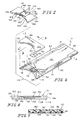
- Fig. 1 is an exploded assembly view of an electrochemical biosensor in accordance with the present invention showing the biosensor including a substrate, a reagent, and a cover;
- Fig. 2 is a bottom perspective view of the cover Fig. 1;
- Fig. 3 is an end view of the biosensor of Fig. 1;
- Fig. 4 is a view taken along lines 4-4 of Fig. 1;
- Fig. 5 is a view taken along lines 5-5 of Fig. 1;
- Fig. 6 is an exploded assembly view of a biosensor in accordance with another aspect of the invention, showing the biosensor including a substrate, a reagent, and cover;
- Fig. 7 is a bottom perspective view of the cover of Fig. 6;
- Fig. 8 is an end view of the biosensor of Fig. 6;
- Fig. 9 is a view taken along lines 9-9 of Fig. 6; and
- Fig. 10 is a perspective view of a biosensor in accordance with another aspect of the invention.
-
- A
biosensor 10 in accordance with the present invention provides a cover with at least one channel carved therein. The channel may be used in a variety of diagnostic biosensors including, for example, electrochemical and photometric sensors. The purpose of the channel is to provide precise fluidic channels for disposable diagnostic tests with high dimensional precision. Various aspects of the invention are presented in Figs. 1-9, which are not drawn to scale and wherein like components in the several views are numbered alike. - Figs. 1-5 illustrate an aspect of the invention in the form of an
electrochemical biosensor 10 having acover 12, abottom substrate 14, electricallyconductive tracks reagent 20 extending over a portion oftracks Biosensor 10 is preferably rectangular in shape. It is appreciated, however, thatbiosensor 10 can assume any number of shapes in accordance with this disclosure.Biosensor 10 is preferably produced from rolls of material, however, it is understood thatbiosensor 10 can be constructed from individual sheets in accordance with this disclosure. Thus, the selection of materials for the construction ofbiosensor 10 necessitates the use of materials that are sufficiently flexible for roll processing, but which are still rigid enough to give a useful stiffness to finishedbiosensor 10. -
Cover 12 ofbiosensor 10 includes afirst surface 48 facingsubstrate 14 and an oppositesecond surface 50. See Figs. 1-2. In addition,cover 12 hasopposite ends edges ends End 52 has a generallyconcave portion 60 that extends betweenedges cover 12 is formed of a flexible polymer and preferably from a polymer such as a polyester. A non-limiting example of a suitable polymer is 7 mil thick ST505 MELINEX® polyester film commercially available from E.I. DuPont de Nemours, Wilmington, Delaware.Cover 12 is coupled tosubstrate 14 by a liquid adhesive. A non-limiting example of such an adhesive is EPO-TEK OH100-4 commercially available from Epoxy Technology, Billerica, MA. It is appreciated thatcover 12 may be coupled tobottom substrate 14 using a wide variety of commercially available adhesives in accordance with this disclosure. - Additionally, as shown in Fig. 2, a
flow channel 62 is carved infirst surface 48 ofcover 12. As used throughout the specification and claims, the term "carve" is defined as to make or get by cutting into a surface, thereby hollowing out a pre-determined space in that surface. Channel 62 extends betweenends first floor portion 36 and asecond floor portion 38. In addition,opposite walls 46 extend fromfirst floor portion 36 andopposite walls 40 extend fromsecond floor portion 38. See Fig. 2.First floor portion 36 andwalls 46 define afirst portion 72 ofchannel 62 andsecond floor portion 38 andwalls 40 define asecond portion 74 ofchannel 62.Walls 46 have a first height as shown byarrows 42 andwalls 40 have a second height as shown byarrows 44.First height 42 is greater than thesecond height 44, so that a liquid sample traveling inchannel 62 encounters increasing capillary forces as the sample enterssecond portion 74 ofchannel 62. Therefore,channel 62 facilitates movement of the liquid sample away fromconcave portion 60 and towardreagent 20 positioned spaced-apart fromend 52. - The height of
walls 46 infirst channel portion 36 is dependent upon the choice of the overall thickness ofcover 12, but generally ranges from about 1 µm to about 150 µm. Preferably, the height ofwalls 46 is from about 75 µm to about 120 µm, and most preferably about 84 µm. The height ofwalls 40 insecond channel portion 38 is also dependent upon the choice of the overall thickness ofcover 12, but generally ranges from about 1 µm to about 75 µm. Preferably the height ofwalls 40 is from about 5 µm to about 50 µm, most preferably about 25 µm. Thechannel portion 38 is approximately 1000 µm to about 4000 µm wide, preferably about 2000 µm to about 3000 µm wide, and most preferably about 2500 µm wide. It is appreciated thatchannel 62 may be formed with a single height or width, or that it may have a variety of heights and widths in accordance with this disclosure so long as the channel meets the design goals for capillarity, meaning that the movement of the liquid sample is facilitated fromportion 60 towardreagent 20. -
Cover 12 ofbiosensor 10 also includessecondary channels 64 carved on either side offlow channel 62. Eachsecondary channel 64 extends between ends 52, 54 and is defined by afloor 66 andwalls 68 extending fromfloor 66.Walls 68 have a height that is less than thesecond height 44. In addition, an adhesive-dispenseaperture 70 extends betweenfloor 66 andsurface 50. The height ofwalls 68 may also vary depending upon the overall thickness ofcover 12, but generally ranges from about 8 µm to about 125 µm. Preferably, the height ofwalls 68 is from about 8 µm to about 75 µm, most preferably about 16µm. It is appreciated that the shape and height ofwalls 68 may vary in accordance with this disclosure. Moreover, it is appreciated that cover 12 may be formed with greater or fewer than two secondary channels in accordance with this disclosure. -
Bottom substrate 14 ofbiosensor 10 includes afirst surface 22 that supportsconductive tracks second surface 24. See Figs. 3-4. In addition,substrate 14 has opposite ends 26, 28 andedges First end 26 includes aconcave portion 76 that is formed with alignment withconcave portion 60 ofcover 12, to accommodate a user's finger. It is appreciated, however, that the design ofportion 76 may vary in accordance with this disclosure.Bottom element 14 may be constructed from a wide variety of insulative materials. Non-limiting examples of insulative materials that provide desirable structural properties include glass, ceramics, vinyl polymers, polyimides, polyesters, and styrenics. Preferably,bottom element 14 is a flexible polymer, such as a polyester or polyimide. A non-limiting example of a suitable material is 5 mil thick KALADEX® , a polyethylene naphthalate film commercially available from E.I. DuPont de Nemours, Wilmington, Delaware, which is coated with gold by LPKF Laser Electronic GmbH, of Garbsen, Germany. -
Biosensors 10 in accordance with the present invention are each formed to include apre-defined reaction area 78 where the sensing takes place. When the biosensor is electrochemical, the pre-defined area is an electrochemical area that is located on a portion of theelectrodes biosensor 10 includes anelectrochemical reaction area 78, which is defined as the area of electrodes wherereagent 20 is located.Recesses 34 are formed insubstrate 14 ofbiosensor 10 and extend aboutarea 78. It is appreciated that recesses 34 can take on any number of shapes and sizes in accordance with this disclosure. The method of forming recesses insubstrate 14 is not limited. For example, the recesses may be formed by indenting, embossing, etching (e.g., using photolithographic methods or laser removal of a portion of the base material), or otherwise deforming or removing a portion of the base material. For a further description of the laser removal of suitable recesses, see U.S. Patent Application No. 09/684,257 entitled BIOSENSOR to Bhullar et al., which was filed in the U.S. Patent and Trademark Office on October 6, 2000, the disclosure of which is expressly incorporated herein by reference. - As shown in Fig. 1, electrically
conductive tracks first surface 24 ofbottom element 14.Tracks biosensor 10. As used herein, the phrase "electrode set" is a set of at least two electrodes, for example 2 to 200, or 3 to 20, electrodes. These electrodes may, for example, be a working electrode and an auxiliary electrode.Tracks recesses 34 and leads 82 that extend from array 80 and betweenrecesses 34 towardend 28. -
Tracks track 16 is a working electrode made of gold, andtrack 18 is an auxiliary electrode that is also made of gold and is substantially the same size as the working electrode. -
Tracks Tracks substrate 14 by a gap having a width of about 25 µm to about 500 µm, preferably the gap has a width of about 100 µm to about 200 µm. Alternatively, it is appreciated that tracks 16, 18 may be created by laser ablation alone onbottom substrate 14. Further, tracks 16, 18 may be laminated, screen-printed, or formed by photolithography in accordance with this disclosure. - Multi-electrode arrangements are also possible in accordance with this disclosure. For example, it is contemplated that a biosensor may be formed that that includes an additional electrically conductive track (not shown). In a three-electrode arrangement, the first track is a working electrode, the second is a counter electrode, and the third electrode is a reference electrode. It is also appreciated that an alternative three-electrode arrangement is possible where tracks are working electrodes and a third electrode is provided as an auxiliary or reference electrode in accordance with this disclosure. It is appreciated that the number of tracks, as well as the spacing between tracks in array 80 may vary in accordance with this disclosure and that a number of arrays may be formed as will be appreciated by one of skill in the art.
-
Reagent 20 provides electrochemical probes for specific analytes and is applied ontobottom substrate 14 such thatreagent 20 covers array 80. The choice ofspecific reagent 20 depends on the specific analyte or analytes to be measured, and are well known to those of ordinary skill in the art. An example of a reagent that may be used inbiosensor 10 of the present invention is a reagent for measuring glucose from a whole blood sample. A non-limiting example of a reagent for measurement of glucose in a human blood sample contains 62.2 mg polyethylene oxide (mean molecular weight of 100-900 kilo Daltons), 3.3 mg NATROSOL 244M, 41.5 mg AVICEL RC-591 F, 89.4 mg monobasic potassium phosphate, 157.9 mg dibasic potassium phosphate, 437.3 mg potassium ferricyanide, 46.0 mg sodium succinate, 148.0 mg trehalose, 2.6 mg TRITON X-100 surfactant, and 2,000 to 9,000 units of enzyme activity per gram of reagent. The enzyme is prepared as an enzyme solution from 12.5 mg coenzyme PQQ and 1.21 million units of the apoenzyme of quinoprotein glucose dehydrogenase. This reagent is further described in U.S. Patent No. 5,997,817, the disclosure of which is expressly incorporated herein by reference. - When hematocrit is to be determined, the reagent includes oxidized and reduced forms of a reversible electroactive compound (potassium hexacyanoferrate (III) ("ferricyanide") and potassium hexacyanoferrate (II) ("ferrocyanide"), respectively), an electrolyte (potassium phosphate buffer), and a microcrystalline material (Avicel RC-591F - a blend of 88% microcrystalline cellulose and 12% sodium carboxymethyl-cellulose, available from FMC Corp.). Concentrations of the components within the reagent before drying are as follows: 400 millimolar (mM) ferricyanide, 55 mM ferrocyanide, 400 mM potassium phosphate, and 2.0% (weight: volume) Avicel. A further description of the reagent for a hematocrit assay is found in U.S. Patent No. 5,385,846, the disclosure of which is expressly incorporated herein by reference.
- Non-limiting examples of enzymes and mediators that may be used in measuring particular analytes in
sensor 10 of the present invention are listed below in Table 1.Analyte Enzymes Mediator (Oxidized Form) Additional Mediator Glucose Glucose Dehydrogenase and Diaphorase Ferricyanide Glucose Glucose-Dehydrogenase (Quinoprotein) Ferricyanide Cholesterol Cholesterol Esterase and Cholesterol Oxidase Ferricyanide 2,6-Dimethyl-1,4-Benzoquinone 2,5-Dichloro-1,4-Benzoquinone or Phenazine Ethosulfate HDL Cholesterol Cholesterol Esterase and Cholesterol Oxidase Ferricyanide 2,6-Dimethyl-1,4-Benzoquinone 2,5-Dichloro-1,4-Benzoquinone or Phenazine Ethosulfate Triglycerides Lipoprotein Lipase, Glycerol Kinase, and Glycerol-3-Phosphate Oxidase Ferricyanide or Phenazine Ethosulfate Phenazine Methosulfate Lactate Lactate Oxidase Ferricyanide 2,6-Dichloro-1,4-Benzoquinone Lactate Lactate Dehydrogenase and Diaphorase Ferricyanide Phenazine Ethosulfate, or Phenazine Methosulfate Lactate Dehydrogenase Diaphorase Ferricyanide Phenazine Ethosulfate, or Phenazine Methosulfate Pyruvate Pyruvate Oxidase Ferricyanide Alcohol Alcohol Oxidase Phenylenediamine Bilirubin Bilirubin Oxidase 1-Methoxy-Phenazine Methosulfate Uric Acid Uricase Ferricyanide - In some of the examples shown in Table 1, at least one additional enzyme is used as a reaction catalyst. Also, some of the examples shown in Table 1 may utilize an additional mediator, which facilitates electron transfer to the oxidized form of the mediator. The additional mediator may be provided to the reagent in lesser amount than the oxidized form of the mediator. While the above assays are described, it is contemplated that current, charge, impedance, conductance, potential, or other electrochemically indicated property of the sample might be accurately correlated to the concentration of the analyte in the sample with
biosensor 10 in accordance with this disclosure. - A plurality of
biosensors 10 are typically packaged in a vial, usually with a stopper formed to seal the vial. It is appreciated, however, thatbiosensors 10 may be packaged individually, or biosensors can be folded upon one another, rolled in a coil, stacked in cassette magazine, or packed in a blister packaging. -
Biosensor 10 is used in conjunction with the following: - 1. a power source in electrical connection with
tracks - 2. a meter in electrical connection with
tracks -
- The meter will normally be adapted to apply an algorithm to the current measurement, whereby an analyte concentration is provided and visually displayed. Improvements in such power source, meter, and biosensor system are the subject of commonly assigned U.S. Pat. No. 4,963,814, issued Oct. 16, 1990; U.S. Pat. No. 4,999,632, issued Mar. 12, 1991; U.S. Pat. No. 4,999,582, issued Mar. 12, 1991; U.S. Pat. No. 5,243,516, issued Sep. 7, 1993; U.S. Pat. No. 5,352,351, issued Oct. 4, 1994; U.S. Pat. No. 5,366,609, issued Nov. 22, 1994; White et al., U.S. Pat. No. 5,405,511, issued Apr. 11, 1995; and White et al., U.S. Pat. No. 5,438,271, issued Aug. 1, 1995, the disclosures of which are expressly incorporated herein by reference.
- Many fluid samples may be analyzed. For example, human body fluids such as whole blood, plasma, sera, lymph, bile, urine, semen, cerebrospinal fluid, spinal fluid, lacrimal fluid and stool specimens as well as other biological fluids readily apparent to one skilled in the art may be measured. Fluid preparations of tissues can also be assayed, along with foods, fermentation products and environmental substances, which potentially contain environmental contaminants. Preferably, whole blood is assayed with this invention.
- After reaction is complete, a power source (e.g., a battery) applies a potential difference between electrodes. When the potential difference is applied, the amount of oxidized form of the mediator at the auxiliary electrode and the potential difference must be sufficient to cause diffusion-limited electro-oxidation of the reduced form of the mediator at the surface of the working electrode. A current measuring meter (not shown) measures the diffusion-limited current generated by the oxidation of the reduced form of the mediator at the surface of the working electrode. The measured current may be accurately correlated to the concentration of the analyte in sample when the following requirements are satisfied:
- 1. The rate of oxidation of the reduced form of the mediator is governed by the rate of diffusion of the reduced form of the mediator to the surface of the working electrode.
- 2. The current produced is limited by the oxidation of reduced form of the mediator at the surface of the working electrode.
-
- To manufacture biosensor 10 a roll of metallized film is fed through guide rolls into an ablation/washing and drying station. A laser system capable of ablating
substrate 14 is known to those of ordinary skill in the art. Non-limiting examples of which include excimer lasers, with the pattern of ablation controlled by mirrors, lenses, and masks. A non-limiting example of such a system is the LPX-300 or LPX-200 both commercially available from LPKF Laser Electronic GmbH, of Garbsen, Germany. - In the laser ablator, the metallic layer of the metallized film is ablated in pre-determined patterns, to form a ribbon of isolated electrode sets. The metallized film is further ablated, after the isolated electrode sets are formed to create
recesses 34 positioned adjacent to each electrochemical area. The ribbon is then passed through more guide rolls, with a tension loop and through an optional optical or electrical inspection system. This inspection system is used for quality control in order to check for defects. -
Reagent 20 is compounded and applied in a liquid form to the center of the electrochemical area at a dispensing and drying station. Reagent application techniques are well known to one of ordinary skill in the art as described in U.S. Patent No. 5,762,770, the disclosure of which is expressly incorporated herein by reference. It is appreciated that reagent may be applied to the electrochemical area in a liquid or other form and dried or semi-dried onto the center of the electrochemical the electrochemical area in accordance with this disclosure. - In addition, a roll of cover material is fed into a laser ablator system as described above. In the laser ablator, the cover material is ablated in pre-determined channel patterns to form a ribbon of channel sets. Each channel set includes a
flow channel 62 that is ablated to a depth of about 84 µm atfirst floor portion second floor portion 38. In addition, each channel set includessecondary channels 64 that are each ablated to a depth of about 16 µm. - The cover material is then fed into a punching station where adhesive-dispense
aperture 70 is punched through eachsecondary channel 64. - The ribbon of channel sets is unwound and fed into a sensor assembly station along with the reagent-coated bottom substrate.
Cover 12 is placed onsubstrate 14 to coverreagent 20. Next, adhesive is dispensed through eachaperture 70 into thesecondary channels 64 while thecover 12 andsubstrate 14 are being compressed. It is appreciated that a number of commercially available dispense units may be used to apply the adhesive intoapertures 70 in accordance with this disclosure. The assembled and time-cured material is then cut to formindividual biosensors 10, which are sorted and packed into vials, each closed with a stopper, to give packaged sensor strips. - Although ablating
channels channels cover 12 is also not limited. For example, the channels may be carved by etching (e.g., using photolithographic methods) or otherwise removing a portion of the surface ofcover 12. In addition, the dimensions of the channels can vary based on the amount of sample to be analyzed and the surface area of the testing area. - The processes and products described above include disposable biosensor, especially for use in diagnostic devices. Also included, however, are electrochemical sensors for non-diagnostic uses, such as measuring an analyte in any biological, environmental, or other sample. As discussed above,
biosensor 10 can be manufactured in a variety of shapes and sizes. - In use, a user of
biosensor 10 places a finger on concave ends 60, 76. Capillary forces pull a liquid sample from ends 60, 76 throughfirst portion 72 ofchannel 62.Walls 46 infirst portion 72 ofchannel 62 converge as they approachsecond portion 74, increasing the capillary forces applied to the liquid sample. Thus, the liquid sample passes through the convergingfirst portion 72 and encounterssecond portion 74 ofchannel 62 andreagent 20. Liquid sample dissolvesreagent 20 and engageselectrode array 78, where the electrochemical reaction takes place. - Referring now to Figs. 6-9,
biosensor 110 is provided in accordance with this invention.Biosensor 110 includes acover 112,bottom substrate 114, andreagent 20.Biosensor 110 is preferably rectangular in shape. It is appreciated, however, thatbiosensor 110 can assume any number of shapes in accordance with this disclosure.Biosensor 110 is preferably produced from rolls of material. Thus, the selection of materials for the construction ofbiosensor 110 necessitates the use of materials that are sufficiently flexible for roll processing, but which are still rigid enough to give a useful stiffness tofinished biosensor 110. - Cover 112 of
biosensor 110 includes afirst surface 148 facingsubstrate 114 and an oppositesecond surface 150. See Figs. 6-7. In addition,cover 112 has opposite ends 152, 154 andedges ends End 152 has a generallyconcave portion 160 that extends betweenedges -
Substrate 114 is similar to substrate14, except that, upon assembly ofbiosensor 110,surface 22 is not completely coated with an electric conductor. Instead, surface 22 is exposed between aboutelectrodes - Cover 112 is coupled to
substrate 114 by an adhesive 116 that is coated on eithersubstrate 114 orcover 112. Adhesive is preferably an adhesive as described above with reference tobiosensor 10 or a thermoset adhesive. A non-limiting example of a suitable thermoset adhesive is a mixture of 95% wt./wt. of Item #38-868 polyurethane and 5% wt./wt. Item #38-8569 isocyanate both commercially available from National Starch& Chemical, a Member of ICI Group, Bridgewater, NJ. It is appreciated thatcover 112 may be coupled tobottom substrate 114 using a wide variety of commercially available adhesives as well as heat sealing, or ultrasonic methods of joiningcover 112 and substrate may be used to couplecover 112 andsubstrate 114 together in accordance with this disclosure. - Additionally, as shown in Fig. 7, a
flow channel 162 is carved infirst surface 148 ofcover 112.Channel 162 extends between ends 152, 154.Channel 162 includes afirst floor portion 136 and asecond floor portion 138 definechannel 162. Oppositewalls 146 extend fromfirst floor portion 136 andopposite walls 140 extend fromsecond floor portion 138.First floor portion 136 andwalls 146 definefirst portion 172 of channel andsecond floor portion 138 andwalls 140 definesecond portion 174 ofchannel 162. -
Walls 140 that extend fromfirst floor portion 136 have a first height as shown byarrows 142 andwalls 140 extending fromsecond floor portion 138 have a second height as shown byarrows 144.First height 142 is greater than thesecond height 144, so that a liquid sample traveling inchannel 162 encounters a greater capillary force as it enterssecond portion 174 ofchannel 162. Therefore,channel 162 acts to draw the liquid sample away fromconcave portion 160 and towardreagent 20 positioned spaced-apart fromend 152. The height and width of first andsecond channel portions second portions channel 38. It is appreciated thatchannel 162 may be formed with a single height, or that it may have a variety of heights in accordance with this disclosure. - To manufacture biosensor 110 a roll of metallized film is fed through guide rolls into an ablation/washing and drying station as described above with reference to
biosensor 10. In the laser ablator, the metallic layer of the metallized film is ablated in pre-determined electrode patterns, to form a ribbon of electrode sets. The metallized film is further ablated to createrecesses 34 positioned adjacent to each electrochemical area. The ribbon may be optically or electrically inspected as described above with reference tobiosensor 10.Reagent 20 is dispensed onsubstrate 114 as described above with reference tobiosensor 10. Additionally, the thermoset adhesive iscoated substrate 114 on either side of area78. It is appreciated that a number of commercially available dispense units may be used to apply the adhesive ontosubstrate 114 in accordance with this disclosure. - Further, a roll of cover material is fed into a laser system as described above with reference to
biosensor 10. In the laser ablator, the cover material is ablated to form a row of spaced-apart channels 162. Eachchannel 162 is ablated to a depth of about 84 µm at afirst floor portion second floor portion 38. The cover material with spaced-apart rows ofchannels 162 is unwound and fed into a sensor assembly station along with the ribbon of reagent-coated bottom substrates. - The cover material is aligned with the ribbon of reagent-coated bottom substrates so that each
cover 112 extends across eachreagent 20. Next, a hot iron (not shown) of appropriate desirable shape and size is placed uponsurface 150 of eachcover 112 on either side ofchannel 162 tocouple cover 112 andsubstrate 114 together. The assembled material is then cut to formindividual biosensors 110, which are sorted and packed into vials, each closed with a stopper, to give packaged sensor strips. - The method of carving
channel 162 incover 112 is also not limited. For example, the channels may be carved by etching (e.g., using photolithographic methods) or otherwise removing a portion of the surface ofcover 12. In addition, the dimensions of the channels can vary based on the amount of sample to be analyzed and the surface area of the testing area. - The processes and products described above include disposable biosensor, especially for use in diagnostic devices. Also included, however, are electrochemical sensors for non-diagnostic uses, such as measuring an analyte in any biological, environmental, or other sample. As discussed above,
biosensor 110 can be manufactured in a variety of shapes and sizes. - In use, a user of
biosensor 110 places a finger onconcave ends first portion 172 ofchannel 162.Walls 146 infirst portion 172 ofchannel 162 converge as they approachsecond portion 174, increasing the capillary forces applied to the liquid sample. Thus, the liquid sample passes through the convergingfirst portion 172 and encounterssecond portion 174 ofchannel 162 andreagent 20. Liquid sample dissolvesreagent 20 and engages electrode array 178, where the electrochemical reaction takes place. - As shown in Fig. 10, a
biosensor 210 is provided in accordance with another aspect of the present invention.Biosensor 210 includes acover 212, abottom substrate 214, andreagent 20.Biosensor 210 is preferably rectangular in shape and formed from materials that are similar tobiosensors - Cover 212 of
biosensor 210 includes aflow channel 262 that is carved infirst surface 48.Flow channel 262 extends between anopening 264 and anair vent 266.Substrate 214 supports tracks 16, 18 andreagent 20.Electrode array 78 and the reagent that coversarray 78, is positioned to lie withinchannel 262 betweenopening 264 andair vent 266.Channel 262 is formed to have two floor portions having heights that are similar tochannel 10. It is appreciated thatchannel 262 may be formed with a single height, or that it may have a variety of heights in accordance with this disclosure. - To manufacture
biosensor 210electrodes substrate 214,reagent 20 is applied toelectrodes substrate 214 in a manner similar to that described above with reference tobiosensor 110. - Further, a roll of cover material is fed into a laser system as described above with reference to
biosensor 10. In the laser ablator, the cover material is ablated to form a row of spaced-apart channels 262. Eachchannel 262 is ablated to a depth of about 84 µm at afirst floor portion second floor portion 38. The cover material with spaced-apart rows ofchannels 262 is unwound and fed into a sensor assembly station along with the ribbon of reagent-coated bottom substrates. - The cover material is aligned with the ribbon of reagent-coated bottom substrates so that each
cover 212 extends across eachreagent 20. Next, a hot iron (not shown) of appropriate desirable shape and size is placed uponsurface 50 of eachcover 212 on either side ofchannel 262 tocouple cover 212 andsubstrate 214 together. The assembled material is then cut to formindividual biosensors 210, which are sorted and packed into vials, each closed with a stopper, to give packaged sensor strips. - The method of carving
channel 262 incover 212 is also not limited. For example, the channels may be carved by etching (e.g., using photolithographic methods) or otherwise removing a portion of the surface ofcover 212. In addition, the dimensions of the channels can vary based on the amount of sample to be analyzed and the surface area of the testing area. - The processes and products described above include disposable biosensor, especially for use in diagnostic devices. Also included, however, are electrochemical sensors for non-diagnostic uses, such as measuring an analyte in any biological, environmental, or other sample. As discussed above,
biosensor 210 can be manufactured in a variety of shapes and sizes. - Although the invention has been described in detail with reference to a preferred embodiment, variations and modifications exist within the scope and spirit of the invention as described and defined in the following claims.
Claims (20)
- A biosensor comprising:a substrate;a reagent positioned on the substrate, anda cover including a first surface coupled to the substrate and a second surface, the first having a flow channel carved therein, the flow channel being aligned with at least a portion of the reagent.
- The biosensor of claim 1, wherein the cover includes opposite ends and the flow channel extends between the ends.
- The biosensor of claim 2, wherein the channel includes a first portion having a first height and a second portion having a second height that is less than the first height.
- The biosensor of claim 3, wherein the first portion includes side walls that converge from one of the ends toward the second portion of the flow channel.
- The biosensor of claim 2, wherein the first portion includes side walls that converge from one of the ends toward the second portion of the flow channel.
- The biosensor of claim 5, wherein the reagent is aligned with the second portion of the flow channel.
- The biosensor of claim 1, wherein the first surface of the cover is formed to include secondary channels.
- The biosensor of claim 7, wherein the secondary channels lie on opposite sides of the flow channel.
- The biosensor of claim 7, wherein the secondary channels are each defined by a floor and a wall extending from the floor and the floor is formed to include an aperture.
- The biosensor of claim 7, further comprising an adhesive positioned in the secondary channels.
- The biosensor of claim 1, further comprising electrodes positioned on the substrate and wherein the channel extends across at least a portion of the electrodes.
- A biosensor comprising:a substrate;a reagent positioned on the substrate; anda cover including opposite ends, a first surface coupled to the substrate, and a second surface, the first surface having a flow channel carved therein, the flow channel extending between the opposite ends.
- The biosensor of claim 12, further comprising electrodes positioned on the substrate and the channel extends across at least a portion of the electrodes.
- The biosensor of claim 13, wherein the cover is formed to include secondary channels.
- The biosensor of claim 14, wherein the secondary channels are spaced-apart from the electrodes.
- The biosensor of claim 12, wherein the channel includes a first portion having a first height and a second portion having a second height that is less than the first height.
- The biosensor of claim 16, wherein the first portion includes walls that converge toward the second portion of the flow channel.
- A method of forming a biosensor, the method comprises the steps of:providing a substrate and a cover having first and second surfaces,applying a reagent onto the substrate to define a reaction zone,carving a channel in the first surface of the cover, andcoupling the cover on the substrate so that the channel extends over at least a portion of the reagent.
- The method of claim 18, wherein the channel is carved by laser ablation.
- The method of claim 18, further comprising the step of forming an electrode set in the reaction zone.
Priority Applications (1)
| Application Number | Priority Date | Filing Date | Title |
|---|---|---|---|
| EP10009879A EP2280277A1 (en) | 2000-11-01 | 2001-10-26 | Biosensor with flow channel |
Applications Claiming Priority (2)
| Application Number | Priority Date | Filing Date | Title |
|---|---|---|---|
| US09/704,145 US6540890B1 (en) | 2000-11-01 | 2000-11-01 | Biosensor |
| US704145 | 2003-11-10 |
Related Child Applications (1)
| Application Number | Title | Priority Date | Filing Date |
|---|---|---|---|
| EP10009879A Division-Into EP2280277A1 (en) | 2000-11-01 | 2001-10-26 | Biosensor with flow channel |
Publications (3)
| Publication Number | Publication Date |
|---|---|
| EP1203956A2 true EP1203956A2 (en) | 2002-05-08 |
| EP1203956A3 EP1203956A3 (en) | 2003-10-22 |
| EP1203956B1 EP1203956B1 (en) | 2015-03-25 |
Family
ID=24828259
Family Applications (2)
| Application Number | Title | Priority Date | Filing Date |
|---|---|---|---|
| EP10009879A Withdrawn EP2280277A1 (en) | 2000-11-01 | 2001-10-26 | Biosensor with flow channel |
| EP01125602.1A Expired - Lifetime EP1203956B1 (en) | 2000-11-01 | 2001-10-26 | Biosensor with flow channel |
Family Applications Before (1)
| Application Number | Title | Priority Date | Filing Date |
|---|---|---|---|
| EP10009879A Withdrawn EP2280277A1 (en) | 2000-11-01 | 2001-10-26 | Biosensor with flow channel |
Country Status (3)
| Country | Link |
|---|---|
| US (2) | US6540890B1 (en) |
| EP (2) | EP2280277A1 (en) |
| JP (1) | JP3821685B2 (en) |
Cited By (11)
| Publication number | Priority date | Publication date | Assignee | Title |
|---|---|---|---|---|
| EP1302545A3 (en) * | 2001-10-09 | 2003-11-05 | Roche Diagnostics GmbH | Enzyme Biosensor |
| EP1385002A1 (en) * | 2002-07-25 | 2004-01-28 | SensLab - Gesellschaft zur Entwicklung und Herstellung bioelektrochemischer Sensoren mbH | Biosensor |
| WO2004062801A1 (en) * | 2003-01-14 | 2004-07-29 | Diagnoswiss S.A. | Multi-layered electrochemical microfluidic sensor comprising reagent on porous layer |
| US6911621B2 (en) | 2000-11-01 | 2005-06-28 | Roche Diagnostics Corporation | Biosensor |
| US7073246B2 (en) | 1999-10-04 | 2006-07-11 | Roche Diagnostics Operations, Inc. | Method of making a biosensor |
| US7287318B2 (en) | 2000-10-06 | 2007-10-30 | Roche Diagnostics Operations, Inc. | Biosensor |
| US20090056120A1 (en) * | 1999-10-04 | 2009-03-05 | Bhullar Raghbir S | Biosensor and method of making |
| CN102128862A (en) * | 2010-01-18 | 2011-07-20 | 惠碁生物科技股份有限公司 | Method for detecting redox substance in food, detection test piece and detector |
| FR2956904A1 (en) * | 2010-03-01 | 2011-09-02 | Eumed Biotechnology Co Ltd | Method for determining oxidizing and reducing substance e.g. sulfur dioxide in food, involves providing reaction potential to reaction electrode of analysis sample and obtaining content of analyzed substance from electrical signal |
| EP2407775A1 (en) * | 2010-07-12 | 2012-01-18 | Arkray, Inc. | Biosensor and biosensor manufacturing method |
| KR101227404B1 (en) | 2010-11-30 | 2013-01-29 | 한국세라믹기술원 | Method of forming channel of bio chip module using mechanical method and bio chip module manufactured by the method |
Families Citing this family (127)
| Publication number | Priority date | Publication date | Assignee | Title |
|---|---|---|---|---|
| US6036924A (en) | 1997-12-04 | 2000-03-14 | Hewlett-Packard Company | Cassette of lancet cartridges for sampling blood |
| US8071384B2 (en) | 1997-12-22 | 2011-12-06 | Roche Diagnostics Operations, Inc. | Control and calibration solutions and methods for their use |
| US7407811B2 (en) | 1997-12-22 | 2008-08-05 | Roche Diagnostics Operations, Inc. | System and method for analyte measurement using AC excitation |
| US7494816B2 (en) | 1997-12-22 | 2009-02-24 | Roche Diagnostic Operations, Inc. | System and method for determining a temperature during analyte measurement |
| US7390667B2 (en) | 1997-12-22 | 2008-06-24 | Roche Diagnostics Operations, Inc. | System and method for analyte measurement using AC phase angle measurements |
| US6391005B1 (en) | 1998-03-30 | 2002-05-21 | Agilent Technologies, Inc. | Apparatus and method for penetration with shaft having a sensor for sensing penetration depth |
| US8641644B2 (en) | 2000-11-21 | 2014-02-04 | Sanofi-Aventis Deutschland Gmbh | Blood testing apparatus having a rotatable cartridge with multiple lancing elements and testing means |
| DE10057832C1 (en) | 2000-11-21 | 2002-02-21 | Hartmann Paul Ag | Blood analysis device has syringe mounted in casing, annular mounting carrying needles mounted behind test strip and being swiveled so that needle can be pushed through strip and aperture in casing to take blood sample |
| US6572745B2 (en) * | 2001-03-23 | 2003-06-03 | Virotek, L.L.C. | Electrochemical sensor and method thereof |
| US7473398B2 (en) * | 2001-05-25 | 2009-01-06 | Roche Diagnostics Operations, Inc. | Biosensor |
| US9795747B2 (en) | 2010-06-02 | 2017-10-24 | Sanofi-Aventis Deutschland Gmbh | Methods and apparatus for lancet actuation |
| US9427532B2 (en) | 2001-06-12 | 2016-08-30 | Sanofi-Aventis Deutschland Gmbh | Tissue penetration device |
| US9226699B2 (en) | 2002-04-19 | 2016-01-05 | Sanofi-Aventis Deutschland Gmbh | Body fluid sampling module with a continuous compression tissue interface surface |
| US7981056B2 (en) | 2002-04-19 | 2011-07-19 | Pelikan Technologies, Inc. | Methods and apparatus for lancet actuation |
| EP1404232B1 (en) | 2001-06-12 | 2009-12-02 | Pelikan Technologies Inc. | Blood sampling apparatus and method |
| AU2002348683A1 (en) | 2001-06-12 | 2002-12-23 | Pelikan Technologies, Inc. | Method and apparatus for lancet launching device integrated onto a blood-sampling cartridge |
| ATE485766T1 (en) | 2001-06-12 | 2010-11-15 | Pelikan Technologies Inc | ELECTRICAL ACTUATING ELEMENT FOR A LANCET |
| JP4209767B2 (en) | 2001-06-12 | 2009-01-14 | ペリカン テクノロジーズ インコーポレイテッド | Self-optimized cutting instrument with adaptive means for temporary changes in skin properties |
| DE60239132D1 (en) | 2001-06-12 | 2011-03-24 | Pelikan Technologies Inc | APPARATUS FOR INCREASING THE SUCCESS RATE IN RESPECT OF BLOOD EXPLOITATION OBTAINED BY A FINGERSTICK |
| US8337419B2 (en) | 2002-04-19 | 2012-12-25 | Sanofi-Aventis Deutschland Gmbh | Tissue penetration device |
| US7025774B2 (en) | 2001-06-12 | 2006-04-11 | Pelikan Technologies, Inc. | Tissue penetration device |
| ATE494837T1 (en) | 2001-06-12 | 2011-01-15 | Pelikan Technologies Inc | INTEGRATED SYSTEM FOR BLOOD SAMPLE ANALYSIS WITH MULTIPLE-USE SAMPLING MODULE |
| JP4282477B2 (en) * | 2001-07-27 | 2009-06-24 | アークレイ株式会社 | Analysis tool |
| US6814844B2 (en) | 2001-08-29 | 2004-11-09 | Roche Diagnostics Corporation | Biosensor with code pattern |
| US6767733B1 (en) | 2001-10-10 | 2004-07-27 | Pritest, Inc. | Portable biosensor apparatus with controlled flow |
| US7344894B2 (en) | 2001-10-16 | 2008-03-18 | Agilent Technologies, Inc. | Thermal regulation of fluidic samples within a diagnostic cartridge |
| EP1448489B1 (en) * | 2001-11-16 | 2010-08-25 | Stefan Ufer | Flexible sensor and method of fabrication |
| US7524293B2 (en) | 2002-04-19 | 2009-04-28 | Pelikan Technologies, Inc. | Method and apparatus for penetrating tissue |
| US7901362B2 (en) | 2002-04-19 | 2011-03-08 | Pelikan Technologies, Inc. | Method and apparatus for penetrating tissue |
| US8784335B2 (en) | 2002-04-19 | 2014-07-22 | Sanofi-Aventis Deutschland Gmbh | Body fluid sampling device with a capacitive sensor |
| US8579831B2 (en) | 2002-04-19 | 2013-11-12 | Sanofi-Aventis Deutschland Gmbh | Method and apparatus for penetrating tissue |
| US8702624B2 (en) | 2006-09-29 | 2014-04-22 | Sanofi-Aventis Deutschland Gmbh | Analyte measurement device with a single shot actuator |
| US7976476B2 (en) | 2002-04-19 | 2011-07-12 | Pelikan Technologies, Inc. | Device and method for variable speed lancet |
| US7563232B2 (en) | 2002-04-19 | 2009-07-21 | Pelikan Technologies, Inc. | Method and apparatus for penetrating tissue |
| US7909778B2 (en) | 2002-04-19 | 2011-03-22 | Pelikan Technologies, Inc. | Method and apparatus for penetrating tissue |
| US9795334B2 (en) | 2002-04-19 | 2017-10-24 | Sanofi-Aventis Deutschland Gmbh | Method and apparatus for penetrating tissue |
| US7582099B2 (en) | 2002-04-19 | 2009-09-01 | Pelikan Technologies, Inc | Method and apparatus for penetrating tissue |
| US7648468B2 (en) | 2002-04-19 | 2010-01-19 | Pelikon Technologies, Inc. | Method and apparatus for penetrating tissue |
| US7232451B2 (en) | 2002-04-19 | 2007-06-19 | Pelikan Technologies, Inc. | Method and apparatus for penetrating tissue |
| US7491178B2 (en) | 2002-04-19 | 2009-02-17 | Pelikan Technologies, Inc. | Method and apparatus for penetrating tissue |
| US7371247B2 (en) | 2002-04-19 | 2008-05-13 | Pelikan Technologies, Inc | Method and apparatus for penetrating tissue |
| US7674232B2 (en) | 2002-04-19 | 2010-03-09 | Pelikan Technologies, Inc. | Method and apparatus for penetrating tissue |
| US7481776B2 (en) | 2002-04-19 | 2009-01-27 | Pelikan Technologies, Inc. | Method and apparatus for penetrating tissue |
| US8267870B2 (en) | 2002-04-19 | 2012-09-18 | Sanofi-Aventis Deutschland Gmbh | Method and apparatus for body fluid sampling with hybrid actuation |
| US7141058B2 (en) | 2002-04-19 | 2006-11-28 | Pelikan Technologies, Inc. | Method and apparatus for a body fluid sampling device using illumination |
| US7713214B2 (en) | 2002-04-19 | 2010-05-11 | Pelikan Technologies, Inc. | Method and apparatus for a multi-use body fluid sampling device with optical analyte sensing |
| US9248267B2 (en) | 2002-04-19 | 2016-02-02 | Sanofi-Aventis Deustchland Gmbh | Tissue penetration device |
| US7410468B2 (en) | 2002-04-19 | 2008-08-12 | Pelikan Technologies, Inc. | Method and apparatus for penetrating tissue |
| US7175642B2 (en) | 2002-04-19 | 2007-02-13 | Pelikan Technologies, Inc. | Methods and apparatus for lancet actuation |
| US9314194B2 (en) | 2002-04-19 | 2016-04-19 | Sanofi-Aventis Deutschland Gmbh | Tissue penetration device |
| US7297122B2 (en) | 2002-04-19 | 2007-11-20 | Pelikan Technologies, Inc. | Method and apparatus for penetrating tissue |
| US7229458B2 (en) | 2002-04-19 | 2007-06-12 | Pelikan Technologies, Inc. | Method and apparatus for penetrating tissue |
| US7892183B2 (en) | 2002-04-19 | 2011-02-22 | Pelikan Technologies, Inc. | Method and apparatus for body fluid sampling and analyte sensing |
| US7374544B2 (en) | 2002-04-19 | 2008-05-20 | Pelikan Technologies, Inc. | Method and apparatus for penetrating tissue |
| US7331931B2 (en) | 2002-04-19 | 2008-02-19 | Pelikan Technologies, Inc. | Method and apparatus for penetrating tissue |
| US7547287B2 (en) | 2002-04-19 | 2009-06-16 | Pelikan Technologies, Inc. | Method and apparatus for penetrating tissue |
| US7717863B2 (en) | 2002-04-19 | 2010-05-18 | Pelikan Technologies, Inc. | Method and apparatus for penetrating tissue |
| US7291117B2 (en) | 2002-04-19 | 2007-11-06 | Pelikan Technologies, Inc. | Method and apparatus for penetrating tissue |
| US8221334B2 (en) | 2002-04-19 | 2012-07-17 | Sanofi-Aventis Deutschland Gmbh | Method and apparatus for penetrating tissue |
| US20040060987A1 (en) * | 2002-05-07 | 2004-04-01 | Green Larry R. | Digital image analysis method for enhanced and optimized signals in fluorophore detection |
| EP1577665B1 (en) * | 2002-12-20 | 2013-06-26 | ARKRAY, Inc. | Thin analyzing test strip |
| NZ523369A (en) * | 2002-12-20 | 2005-08-26 | Dec Int Nz Ltd | Milk processing |
| US8574895B2 (en) | 2002-12-30 | 2013-11-05 | Sanofi-Aventis Deutschland Gmbh | Method and apparatus using optical techniques to measure analyte levels |
| US7225008B1 (en) * | 2003-05-21 | 2007-05-29 | Isense Corporation | Multiple use analyte sensing assembly |
| ES2490740T3 (en) | 2003-06-06 | 2014-09-04 | Sanofi-Aventis Deutschland Gmbh | Apparatus for blood fluid sampling and analyte detection |
| WO2006001797A1 (en) | 2004-06-14 | 2006-01-05 | Pelikan Technologies, Inc. | Low pain penetrating |
| US7604592B2 (en) | 2003-06-13 | 2009-10-20 | Pelikan Technologies, Inc. | Method and apparatus for a point of care device |
| US7452457B2 (en) | 2003-06-20 | 2008-11-18 | Roche Diagnostics Operations, Inc. | System and method for analyte measurement using dose sufficiency electrodes |
| US8679853B2 (en) * | 2003-06-20 | 2014-03-25 | Roche Diagnostics Operations, Inc. | Biosensor with laser-sealed capillary space and method of making |
| US8506775B2 (en) * | 2003-06-20 | 2013-08-13 | Roche Diagnostics Operations, Inc. | Devices and methods relating to electrochemical biosensors |
| US7488601B2 (en) | 2003-06-20 | 2009-02-10 | Roche Diagnostic Operations, Inc. | System and method for determining an abused sensor during analyte measurement |
| US7718439B2 (en) | 2003-06-20 | 2010-05-18 | Roche Diagnostics Operations, Inc. | System and method for coding information on a biosensor test strip |
| KR100785670B1 (en) * | 2003-06-20 | 2007-12-14 | 에프. 호프만-라 로슈 아게 | Method and reagent for producing narrow, homogenous reagent strips |
| US8206565B2 (en) | 2003-06-20 | 2012-06-26 | Roche Diagnostics Operation, Inc. | System and method for coding information on a biosensor test strip |
| US7604721B2 (en) | 2003-06-20 | 2009-10-20 | Roche Diagnostics Operations, Inc. | System and method for coding information on a biosensor test strip |
| US7645421B2 (en) | 2003-06-20 | 2010-01-12 | Roche Diagnostics Operations, Inc. | System and method for coding information on a biosensor test strip |
| US8148164B2 (en) | 2003-06-20 | 2012-04-03 | Roche Diagnostics Operations, Inc. | System and method for determining the concentration of an analyte in a sample fluid |
| US8071030B2 (en) * | 2003-06-20 | 2011-12-06 | Roche Diagnostics Operations, Inc. | Test strip with flared sample receiving chamber |
| US7645373B2 (en) | 2003-06-20 | 2010-01-12 | Roche Diagnostic Operations, Inc. | System and method for coding information on a biosensor test strip |
| US7597793B2 (en) | 2003-06-20 | 2009-10-06 | Roche Operations Ltd. | System and method for analyte measurement employing maximum dosing time delay |
| US8058077B2 (en) | 2003-06-20 | 2011-11-15 | Roche Diagnostics Operations, Inc. | Method for coding information on a biosensor test strip |
| CA2537091A1 (en) * | 2003-09-01 | 2005-03-10 | Inverness Medical Switzerland Gmbh | Sampling device with capillary action |
| US20050260695A1 (en) * | 2003-09-23 | 2005-11-24 | Genprime, Inc. | Methods, compositions, devices, and kits for detecting mastitis |
| EP1671096A4 (en) | 2003-09-29 | 2009-09-16 | Pelikan Technologies Inc | METHOD AND APPARATUS FOR AN IMPROVED SAMPLING INTERFERENCE DEVICE |
| WO2005037095A1 (en) | 2003-10-14 | 2005-04-28 | Pelikan Technologies, Inc. | Method and apparatus for a variable user interface |
| US8668656B2 (en) | 2003-12-31 | 2014-03-11 | Sanofi-Aventis Deutschland Gmbh | Method and apparatus for improving fluidic flow and sample capture |
| US7822454B1 (en) | 2005-01-03 | 2010-10-26 | Pelikan Technologies, Inc. | Fluid sampling device with improved analyte detecting member configuration |
| WO2005078118A1 (en) | 2004-02-06 | 2005-08-25 | Bayer Healthcare Llc | Oxidizable species as an internal reference for biosensors and method of use |
| US7807043B2 (en) * | 2004-02-23 | 2010-10-05 | Oakville Hong Kong Company Limited | Microfluidic test device |
| US8828203B2 (en) | 2004-05-20 | 2014-09-09 | Sanofi-Aventis Deutschland Gmbh | Printable hydrogels for biosensors |
| US9820684B2 (en) | 2004-06-03 | 2017-11-21 | Sanofi-Aventis Deutschland Gmbh | Method and apparatus for a fluid sampling device |
| US7569126B2 (en) | 2004-06-18 | 2009-08-04 | Roche Diagnostics Operations, Inc. | System and method for quality assurance of a biosensor test strip |
| US7556723B2 (en) | 2004-06-18 | 2009-07-07 | Roche Diagnostics Operations, Inc. | Electrode design for biosensor |
| US7608042B2 (en) | 2004-09-29 | 2009-10-27 | Intellidx, Inc. | Blood monitoring system |
| US20070191716A1 (en) * | 2004-09-29 | 2007-08-16 | Daniel Goldberger | Blood monitoring system |
| US20060229531A1 (en) * | 2005-02-01 | 2006-10-12 | Daniel Goldberger | Blood monitoring system |
| US8652831B2 (en) | 2004-12-30 | 2014-02-18 | Sanofi-Aventis Deutschland Gmbh | Method and apparatus for analyte measurement test time |
| WO2006116032A2 (en) * | 2005-04-21 | 2006-11-02 | Ndsu Research Foundation | Radiation curable polymer films having improved laser ablation properties and radiation curable sensitizers therefor |
| EP3483599A1 (en) | 2005-07-20 | 2019-05-15 | Ascensia Diabetes Care Holdings AG | Methods for measuring the concentration of an analyte in solution and for calibrating the measurement as well as handheld devices therefor |
| EP1924848A2 (en) * | 2005-08-16 | 2008-05-28 | Home Diagnostics, Inc. | Method for test strip manufacturing and analysis |
| CN103048442B (en) | 2005-09-30 | 2015-04-08 | 拜尔健康护理有限责任公司 | Gated voltammetry |
| US7510985B1 (en) | 2005-10-26 | 2009-03-31 | Lpkf Laser & Electronics Ag | Method to manufacture high-precision RFID straps and RFID antennas using a laser |
| US20080200838A1 (en) * | 2005-11-28 | 2008-08-21 | Daniel Goldberger | Wearable, programmable automated blood testing system |
| US20070123801A1 (en) * | 2005-11-28 | 2007-05-31 | Daniel Goldberger | Wearable, programmable automated blood testing system |
| US7955484B2 (en) * | 2005-12-14 | 2011-06-07 | Nova Biomedical Corporation | Glucose biosensor and method |
| CN100359354C (en) * | 2006-04-14 | 2008-01-02 | 上海光谱仪器有限公司 | Micro-full analytical system chip height positioning method |
| US8092385B2 (en) * | 2006-05-23 | 2012-01-10 | Intellidx, Inc. | Fluid access interface |
| US7465597B2 (en) | 2006-06-29 | 2008-12-16 | Home Diagnostics, Inc. | Method of manufacturing a diagnostic test strip |
| US7993512B2 (en) * | 2006-07-11 | 2011-08-09 | Bayer Healthcare, Llc | Electrochemical test sensor |
| WO2008021758A1 (en) * | 2006-08-11 | 2008-02-21 | Home Diagnostics, Inc. | Methods for fabricating a biosensor with a surface texture |
| EP2081587A2 (en) * | 2006-10-18 | 2009-07-29 | Research Development Foundation | Alpha-msh therapies for treatment of autoimmune disease |
| EP1964927A1 (en) * | 2007-02-27 | 2008-09-03 | F. Hoffmann-La Roche AG | Quinones as mediators for photometric tests |
| ES2637381T3 (en) * | 2007-10-31 | 2017-10-13 | F. Hoffmann-La Roche Ag | Electrical standards for biosensors and manufacturing procedure |
| WO2009076302A1 (en) | 2007-12-10 | 2009-06-18 | Bayer Healthcare Llc | Control markers for auto-detection of control solution and methods of use |
| US9386944B2 (en) | 2008-04-11 | 2016-07-12 | Sanofi-Aventis Deutschland Gmbh | Method and apparatus for analyte detecting device |
| JP5405916B2 (en) * | 2008-06-24 | 2014-02-05 | パナソニック株式会社 | Biosensor, method for manufacturing the same, and detection system including the same |
| JP5026597B2 (en) | 2008-11-04 | 2012-09-12 | パナソニック株式会社 | Measuring apparatus, measuring method and program |
| US9375169B2 (en) | 2009-01-30 | 2016-06-28 | Sanofi-Aventis Deutschland Gmbh | Cam drive for managing disposable penetrating member actions with a single motor and motor and control system |
| US8753290B2 (en) * | 2009-03-27 | 2014-06-17 | Intellectual Inspiration, Llc | Fluid transfer system and method |
| US8965476B2 (en) | 2010-04-16 | 2015-02-24 | Sanofi-Aventis Deutschland Gmbh | Tissue penetration device |
| EP2760825B1 (en) | 2011-09-28 | 2016-09-14 | F.Hoffmann-La Roche Ag | Azo mediators |
| JP6352954B2 (en) | 2013-03-15 | 2018-07-04 | エフ.ホフマン−ラ ロシュ アーゲーF. Hoffmann−La Roche Aktiengesellschaft | Method and device for using information from recovery pulses in electrochemical analyte measurement, apparatus and system incorporating them |
| CA2949909C (en) | 2013-03-15 | 2019-10-01 | F. Hoffmann-La Roche Ag | Methods of scaling data used to construct biosensor algorithms as well as devices, apparatuses and systems incorporating the same |
| JP6412027B2 (en) | 2013-03-15 | 2018-10-24 | エフ.ホフマン−ラ ロシュ アーゲーF. Hoffmann−La Roche Aktiengesellschaft | Method for fail-safe electrochemical measurement of analyte and device, apparatus and system incorporating the same |
| EP2972269B1 (en) | 2013-03-15 | 2018-07-11 | Roche Diabetes Care GmbH | Methods of detecting high antioxidant levels during electrochemical measurements and failsafing an analyte concentration therefrom |
| JP2019529935A (en) | 2016-10-05 | 2019-10-17 | エフ ホフマン−ラ ロッシュ アクチェン ゲゼルシャフト | Detection reagents and electrode arrangements for multi-sample diagnostic test elements and methods of using them |
| WO2018080637A1 (en) | 2016-10-24 | 2018-05-03 | Roche Diabetes Care, Inc. | Methods of correcting for uncompensated resistances in the conductive elements of biosensors, as well as devices and systems |
Family Cites Families (105)
| Publication number | Priority date | Publication date | Assignee | Title |
|---|---|---|---|---|
| US4081653A (en) | 1976-12-27 | 1978-03-28 | Western Electric Co., Inc. | Removal of thin films from substrates by laser induced explosion |
| US4131484A (en) | 1978-02-13 | 1978-12-26 | Western Electric Company, Inc. | Frequency adjusting a piezoelectric device by lasering |
| DE2928496A1 (en) * | 1979-07-14 | 1981-01-29 | Bosch Gmbh Robert | ELECTROCHEMICAL PROBE FOR DETERMINING THE OXYGEN CONTENT IN GASES |
| JPS56100451A (en) | 1980-01-14 | 1981-08-12 | Matsushita Electric Ind Co Ltd | Manufacture of electrode of semiconductor device |
| US4414059A (en) | 1982-12-09 | 1983-11-08 | International Business Machines Corporation | Far UV patterning of resist materials |
| US5509410A (en) | 1983-06-06 | 1996-04-23 | Medisense, Inc. | Strip electrode including screen printing of a single layer |
| US5682884A (en) | 1983-05-05 | 1997-11-04 | Medisense, Inc. | Strip electrode with screen printing |
| WO1986007632A1 (en) | 1985-06-21 | 1986-12-31 | Matsushita Electric Industrial Co., Ltd. | Biosensor and method of manufacturing same |
| US4684437A (en) | 1985-10-31 | 1987-08-04 | International Business Machines Corporation | Selective metal etching in metal/polymer structures |
| US4865873A (en) | 1986-09-15 | 1989-09-12 | General Electric Company | Electroless deposition employing laser-patterned masking layer |
| DE3711511C1 (en) * | 1987-04-04 | 1988-06-30 | Hartmann & Braun Ag | Method for determining gas concentrations in a gas mixture and sensor for measuring thermal conductivity |
| US4874500A (en) | 1987-07-15 | 1989-10-17 | Sri International | Microelectrochemical sensor and sensor array |
| DE68924026T3 (en) | 1988-03-31 | 2008-01-10 | Matsushita Electric Industrial Co., Ltd., Kadoma | BIOSENSOR AND ITS MANUFACTURE. |
| EP0376721B1 (en) * | 1988-12-29 | 1998-07-15 | Sharp Kabushiki Kaisha | Moisture-sensitive device |
| US4957582A (en) | 1989-03-16 | 1990-09-18 | Eastman Kodak Company | Capillary transport zone coated with adhesive |
| WO1991002391A1 (en) | 1989-08-02 | 1991-02-21 | Australian Electro Optics Pty. Ltd. | A diode laser system emitting a high quality laser beam of circular cross-section perpendicular to the mounting base |
| US5018164A (en) | 1989-09-12 | 1991-05-21 | Hughes Aircraft Company | Excimer laser ablation method and apparatus for microcircuit fabrication |
| US5089103A (en) | 1989-12-01 | 1992-02-18 | Hewlett-Packard Company | Electrophoresis capillary with agarose |
| GB8927377D0 (en) | 1989-12-04 | 1990-01-31 | Univ Edinburgh | Improvements in and relating to amperometric assays |
| US5508171A (en) | 1989-12-15 | 1996-04-16 | Boehringer Mannheim Corporation | Assay method with enzyme electrode system |
| CA2069946C (en) | 1989-12-15 | 1999-01-26 | Klaus H. Pollmann | Redox mediator reagent and biosensor |
| US4999632A (en) | 1989-12-15 | 1991-03-12 | Boehringer Mannheim Corporation | Analog to digital conversion with noise reduction |
| US5243516A (en) | 1989-12-15 | 1993-09-07 | Boehringer Mannheim Corporation | Biosensing instrument and method |
| US4963814A (en) | 1989-12-15 | 1990-10-16 | Boehringer Mannheim Corporation | Regulated bifurcated power supply |
| US4999582A (en) | 1989-12-15 | 1991-03-12 | Boehringer Mannheim Corp. | Biosensor electrode excitation circuit |
| US5165407A (en) | 1990-04-19 | 1992-11-24 | The University Of Kansas | Implantable glucose sensor |
| JPH0820412B2 (en) | 1990-07-20 | 1996-03-04 | 松下電器産業株式会社 | Quantitative analysis method and device using disposable sensor |
| US5104480A (en) | 1990-10-12 | 1992-04-14 | General Electric Company | Direct patterning of metals over a thermally inefficient surface using a laser |
| WO1992017994A1 (en) | 1991-04-01 | 1992-10-15 | Filial Vsesojuznogo Nauchno-Issledovatelskogo Instituta Elektromekhaniki | Multilayer printed circuit board and method of manufacture |
| JP3118015B2 (en) | 1991-05-17 | 2000-12-18 | アークレイ株式会社 | Biosensor and separation and quantification method using the same |
| US5264103A (en) | 1991-10-18 | 1993-11-23 | Matsushita Electric Industrial Co., Ltd. | Biosensor and a method for measuring a concentration of a substrate in a sample |
| KR100274764B1 (en) | 1991-11-29 | 2001-01-15 | 이사오 우치가사키 | Manufacturing method of the wiring board |
| US5336388A (en) | 1991-12-26 | 1994-08-09 | Ppg Industries, Inc. | Analyte and pH measuring sensor assembly and method |
| JPH05315703A (en) | 1992-05-13 | 1993-11-26 | Sumitomo Electric Ind Ltd | Semiconductor laser manufacturing method |
| JP2541081B2 (en) * | 1992-08-28 | 1996-10-09 | 日本電気株式会社 | Biosensor and method of manufacturing and using biosensor |
| DE4233178A1 (en) * | 1992-10-02 | 1994-04-07 | Bosch Gmbh Robert | Electrochemical oxygen measuring probe for waste gases - has protective sintered glass-contg. foil with gas passages |
| GB9221099D0 (en) | 1992-10-07 | 1992-11-18 | Ecossensors Ltd | Improvements in and relating to gas permeable membranes for amperometric gas electrodes |
| FR2701117B1 (en) | 1993-02-04 | 1995-03-10 | Asulab Sa | Electrochemical measurement system with multizone sensor, and its application to glucose measurement. |
| DE4310106C1 (en) | 1993-03-27 | 1994-10-06 | Bruker Saxonia Analytik Gmbh | Manufacturing process for switching grids of an ion mobility spectrometer and switching grids manufactured according to the process |
| US5390412A (en) | 1993-04-08 | 1995-02-21 | Gregoire; George D. | Method for making printed circuit boards |
| US5387329A (en) * | 1993-04-09 | 1995-02-07 | Ciba Corning Diagnostics Corp. | Extended use planar sensors |
| US5385846A (en) | 1993-06-03 | 1995-01-31 | Boehringer Mannheim Corporation | Biosensor and method for hematocrit determination |
| US5405511A (en) | 1993-06-08 | 1995-04-11 | Boehringer Mannheim Corporation | Biosensing meter with ambient temperature estimation method and system |
| US5366609A (en) | 1993-06-08 | 1994-11-22 | Boehringer Mannheim Corporation | Biosensing meter with pluggable memory key |
| EP0702789B8 (en) | 1993-06-08 | 2006-06-14 | Roche Diagnostics Operations, Inc. | Biosensing meter which detects proper electrode engagement and distinguishes sample and check strips |
| US5352351A (en) | 1993-06-08 | 1994-10-04 | Boehringer Mannheim Corporation | Biosensing meter with fail/safe procedures to prevent erroneous indications |
| US5413690A (en) | 1993-07-23 | 1995-05-09 | Boehringer Mannheim Corporation | Potentiometric biosensor and the method of its use |
| JPH0766499A (en) | 1993-08-25 | 1995-03-10 | Honda Motor Co Ltd | Semiconductor laser manufacturing method |
| US5589326A (en) | 1993-12-30 | 1996-12-31 | Boehringer Mannheim Corporation | Osmium-containing redox mediator |
| US5762770A (en) | 1994-02-21 | 1998-06-09 | Boehringer Mannheim Corporation | Electrochemical biosensor test strip |
| WO1995022881A1 (en) | 1994-02-22 | 1995-08-24 | Philips Electronics N.V. | Laser etching method |
| US5437999A (en) | 1994-02-22 | 1995-08-01 | Boehringer Mannheim Corporation | Electrochemical sensor |
| US5391250A (en) | 1994-03-15 | 1995-02-21 | Minimed Inc. | Method of fabricating thin film sensors |
| JPH07290751A (en) | 1994-04-22 | 1995-11-07 | Matsushita Electric Ind Co Ltd | Powder flying recording device |
| DE4417245A1 (en) | 1994-04-23 | 1995-10-26 | Lpkf Cad Cam Systeme Gmbh | High resolution structured metallisation prodn. |
| EP0727925A1 (en) | 1995-02-14 | 1996-08-21 | Lpkf Cad/Cam Systeme Gmbh | Process for structured metallizing of the surface of substrates |
| KR970705839A (en) | 1995-06-27 | 1997-10-09 | 제이.쥐.에이.롤페즈 | METHOD OF MANUFACTURING MULTILAYER ELECTRONIC COMPONENTS |
| DE19535068C2 (en) | 1995-09-21 | 1997-08-21 | Lpkf Cad Cam Systeme Gmbh | Coating for the structured production of conductor tracks on the surface of electrically insulating substrates, method for producing the coating and of structured conductor tracks |
| US5628890A (en) | 1995-09-27 | 1997-05-13 | Medisense, Inc. | Electrochemical sensor |
| JPH09207343A (en) | 1995-11-29 | 1997-08-12 | Matsushita Electric Ind Co Ltd | Laser processing method |
| US5755953A (en) | 1995-12-18 | 1998-05-26 | Abbott Laboratories | Interference free biosensor |
| JP3365184B2 (en) | 1996-01-10 | 2003-01-08 | 松下電器産業株式会社 | Biosensor |
| US5708247A (en) | 1996-02-14 | 1998-01-13 | Selfcare, Inc. | Disposable glucose test strips, and methods and compositions for making same |
| JP3100897B2 (en) | 1996-03-26 | 2000-10-23 | 三洋電機株式会社 | Manufacturing method of integrated solar cell device |
| US5800690A (en) | 1996-07-03 | 1998-09-01 | Caliper Technologies Corporation | Variable control of electroosmotic and/or electrophoretic forces within a fluid-containing structure via electrical forces |
| JP3305206B2 (en) | 1996-08-09 | 2002-07-22 | 三菱重工業株式会社 | Laser processing equipment |
| JP3510740B2 (en) | 1996-08-26 | 2004-03-29 | シャープ株式会社 | Manufacturing method of integrated thin-film solar cell |
| KR100243656B1 (en) | 1996-12-05 | 2000-02-01 | 정선종 | A vertical-cavity surface-emitting LASER with hydrogenation treatment and method for fabricating the same |
| GB9702388D0 (en) | 1997-02-06 | 1997-03-26 | Bio Rad Micromeasurements Ltd | Selective interferometry |
| AU6157898A (en) | 1997-02-06 | 1998-08-26 | E. Heller & Company | Small volume (in vitro) analyte sensor |
| JPH10241992A (en) | 1997-02-24 | 1998-09-11 | Taiyo Yuden Co Ltd | Multilayer capacitor and its trimming method |
| JPH10275959A (en) | 1997-03-28 | 1998-10-13 | Pioneer Electron Corp | Method of manufacturing distributed feedback semiconductor laser device and distributed feedback semiconductor laser device |
| JPH10303444A (en) | 1997-04-25 | 1998-11-13 | Sharp Corp | Solar cell manufacturing method |
| GB9708585D0 (en) | 1997-04-29 | 1997-06-18 | Eastman Kodak Co | Apparatus, magazine and method for electrochemical detection or measurement |
| WO1998049773A1 (en) | 1997-04-30 | 1998-11-05 | The Whitaker Corporation | High frequency surface acoustic wave devices for radio frequency applications and the method of fabricating the same |
| US5759364A (en) | 1997-05-02 | 1998-06-02 | Bayer Corporation | Electrochemical biosensor |
| US5798031A (en) | 1997-05-12 | 1998-08-25 | Bayer Corporation | Electrochemical biosensor |
| GB9711395D0 (en) | 1997-06-04 | 1997-07-30 | Environmental Sensors Ltd | Improvements to electrodes for the measurement of analytes in small samples |
| US5948695A (en) * | 1997-06-17 | 1999-09-07 | Mercury Diagnostics, Inc. | Device for determination of an analyte in a body fluid |
| US6309526B1 (en) | 1997-07-10 | 2001-10-30 | Matsushita Electric Industrial Co., Ltd. | Biosensor |
| US6129823A (en) | 1997-09-05 | 2000-10-10 | Abbott Laboratories | Low volume electrochemical sensor |
| JP3809713B2 (en) | 1997-09-09 | 2006-08-16 | 富士通株式会社 | TDI circuit, image signal readout circuit, and imaging device |
| US5997817A (en) | 1997-12-05 | 1999-12-07 | Roche Diagnostics Corporation | Electrochemical biosensor test strip |
| US6165594A (en) | 1998-01-15 | 2000-12-26 | 3M Innovative Properties Company | Multilayer, temperature resistant, composite label |
| US6103033A (en) | 1998-03-04 | 2000-08-15 | Therasense, Inc. | Process for producing an electrochemical biosensor |
| US6134461A (en) | 1998-03-04 | 2000-10-17 | E. Heller & Company | Electrochemical analyte |
| JP3867284B2 (en) | 1998-04-13 | 2007-01-10 | 千住金属工業株式会社 | Method of forming solder bump |
| US6175752B1 (en) | 1998-04-30 | 2001-01-16 | Therasense, Inc. | Analyte monitoring device and methods of use |
| JP3874321B2 (en) * | 1998-06-11 | 2007-01-31 | 松下電器産業株式会社 | Biosensor |
| US6338790B1 (en) | 1998-10-08 | 2002-01-15 | Therasense, Inc. | Small volume in vitro analyte sensor with diffusible or non-leachable redox mediator |
| JP2000121594A (en) | 1998-10-15 | 2000-04-28 | Kdk Corp | Biosensor |
| US6203952B1 (en) | 1999-01-14 | 2001-03-20 | 3M Innovative Properties Company | Imaged article on polymeric substrate |
| US6287451B1 (en) | 1999-06-02 | 2001-09-11 | Handani Winarta | Disposable sensor and method of making |
| US6258229B1 (en) | 1999-06-02 | 2001-07-10 | Handani Winarta | Disposable sub-microliter volume sensor and method of making |
| US6662439B1 (en) | 1999-10-04 | 2003-12-16 | Roche Diagnostics Corporation | Laser defined features for patterned laminates and electrodes |
| US6645359B1 (en) | 2000-10-06 | 2003-11-11 | Roche Diagnostics Corporation | Biosensor |
| US20020139668A1 (en) * | 1999-11-03 | 2002-10-03 | Raghbir Singh Bhullar | Embedded metallic deposits |
| EP2275807B1 (en) | 1999-11-15 | 2014-04-23 | Panasonic Healthcare Co., Ltd. | Biosensor for quantifying a substrate |
| CN1191475C (en) | 2000-03-31 | 2005-03-02 | 生命扫描有限公司 | Medical diagnostic device for measuring analyte concentration of conductive biological fluid |
| US6696008B2 (en) | 2000-05-25 | 2004-02-24 | Westar Photonics Inc. | Maskless laser beam patterning ablation of multilayered structures with continuous monitoring of ablation |
| KR100497020B1 (en) | 2000-05-29 | 2005-06-23 | 마츠시타 덴끼 산교 가부시키가이샤 | Biosensor and method for its preparation |
| DE50008242D1 (en) | 2000-09-26 | 2004-11-18 | Enthone Omi Deutschland Gmbh | Process for the selective metallization of dielectric materials |
| US6540890B1 (en) | 2000-11-01 | 2003-04-01 | Roche Diagnostics Corporation | Biosensor |
| CN100401050C (en) | 2001-04-16 | 2008-07-09 | 松下电器产业株式会社 | biological sensor |
| WO2002097418A1 (en) | 2001-05-29 | 2002-12-05 | Matsushita Electric Industrial Co., Ltd. | Biosensor |
-
2000
- 2000-11-01 US US09/704,145 patent/US6540890B1/en not_active Expired - Lifetime
-
2001
- 2001-10-25 JP JP2001327824A patent/JP3821685B2/en not_active Expired - Fee Related
- 2001-10-26 EP EP10009879A patent/EP2280277A1/en not_active Withdrawn
- 2001-10-26 EP EP01125602.1A patent/EP1203956B1/en not_active Expired - Lifetime
-
2003
- 2003-01-08 US US10/338,498 patent/US6911621B2/en not_active Expired - Fee Related
Non-Patent Citations (1)
| Title |
|---|
| None |
Cited By (20)
| Publication number | Priority date | Publication date | Assignee | Title |
|---|---|---|---|---|
| US8287703B2 (en) | 1999-10-04 | 2012-10-16 | Roche Diagnostics Operations, Inc. | Biosensor and method of making |
| US7073246B2 (en) | 1999-10-04 | 2006-07-11 | Roche Diagnostics Operations, Inc. | Method of making a biosensor |
| US20090056120A1 (en) * | 1999-10-04 | 2009-03-05 | Bhullar Raghbir S | Biosensor and method of making |
| US8551308B2 (en) * | 1999-10-04 | 2013-10-08 | Roche Diagnostics Operations, Inc. | Biosensor and method of making |
| US7287318B2 (en) | 2000-10-06 | 2007-10-30 | Roche Diagnostics Operations, Inc. | Biosensor |
| US6911621B2 (en) | 2000-11-01 | 2005-06-28 | Roche Diagnostics Corporation | Biosensor |
| US6755949B1 (en) | 2001-10-09 | 2004-06-29 | Roche Diagnostics Corporation | Biosensor |
| EP1302545A3 (en) * | 2001-10-09 | 2003-11-05 | Roche Diagnostics GmbH | Enzyme Biosensor |
| EP1385002A1 (en) * | 2002-07-25 | 2004-01-28 | SensLab - Gesellschaft zur Entwicklung und Herstellung bioelektrochemischer Sensoren mbH | Biosensor |
| WO2004062801A1 (en) * | 2003-01-14 | 2004-07-29 | Diagnoswiss S.A. | Multi-layered electrochemical microfluidic sensor comprising reagent on porous layer |
| CN102128862B (en) * | 2010-01-18 | 2014-04-23 | 惠碁生物科技股份有限公司 | Detection method, detection test piece and detection instrument for redox substances in food |
| CN102128862A (en) * | 2010-01-18 | 2011-07-20 | 惠碁生物科技股份有限公司 | Method for detecting redox substance in food, detection test piece and detector |
| FR2956904A1 (en) * | 2010-03-01 | 2011-09-02 | Eumed Biotechnology Co Ltd | Method for determining oxidizing and reducing substance e.g. sulfur dioxide in food, involves providing reaction potential to reaction electrode of analysis sample and obtaining content of analyzed substance from electrical signal |
| CN102375051A (en) * | 2010-07-12 | 2012-03-14 | 爱科来株式会社 | Biosensor and biosensor manufacturing method |
| EP2407775A1 (en) * | 2010-07-12 | 2012-01-18 | Arkray, Inc. | Biosensor and biosensor manufacturing method |
| CN102375051B (en) * | 2010-07-12 | 2014-07-30 | 爱科来株式会社 | Biosensor and biosensor manufacturing method |
| US8920747B2 (en) | 2010-07-12 | 2014-12-30 | Arkray, Inc. | Biosensor and biosensor manufacturing method |
| KR101528826B1 (en) * | 2010-07-12 | 2015-06-17 | 아크레이 가부시키가이샤 | Biosensor and biosensor sample liquid sucking method |
| US9506889B2 (en) | 2010-07-12 | 2016-11-29 | Arkray, Inc. | Biosensor and biosensor manufacturing method |
| KR101227404B1 (en) | 2010-11-30 | 2013-01-29 | 한국세라믹기술원 | Method of forming channel of bio chip module using mechanical method and bio chip module manufactured by the method |
Also Published As
| Publication number | Publication date |
|---|---|
| EP2280277A1 (en) | 2011-02-02 |
| EP1203956B1 (en) | 2015-03-25 |
| JP2002195972A (en) | 2002-07-10 |
| EP1203956A3 (en) | 2003-10-22 |
| JP3821685B2 (en) | 2006-09-13 |
| US6911621B2 (en) | 2005-06-28 |
| US6540890B1 (en) | 2003-04-01 |
| US20030094367A1 (en) | 2003-05-22 |
Similar Documents
| Publication | Publication Date | Title |
|---|---|---|
| US6911621B2 (en) | Biosensor | |
| US6814843B1 (en) | Biosensor | |
| US6447657B1 (en) | Biosensor | |
| US7287318B2 (en) | Biosensor | |
| US7473398B2 (en) | Biosensor | |
| US6755949B1 (en) | Biosensor | |
| US6866758B2 (en) | Biosensor | |
| US7479211B2 (en) | Biosensor | |
| EP1288653B1 (en) | Biosensor with a bar code | |
| CA2547681C (en) | Biosensor |
Legal Events
| Date | Code | Title | Description |
|---|---|---|---|
| PUAI | Public reference made under article 153(3) epc to a published international application that has entered the european phase |
Free format text: ORIGINAL CODE: 0009012 |
|
| AK | Designated contracting states |
Kind code of ref document: A2 Designated state(s): AT BE CH CY DE DK ES FI FR GB GR IE IT LI LU MC NL PT SE TR |
|
| AX | Request for extension of the european patent |
Free format text: AL;LT;LV;MK;RO;SI |
|
| PUAL | Search report despatched |
Free format text: ORIGINAL CODE: 0009013 |
|
| AK | Designated contracting states |
Kind code of ref document: A3 Designated state(s): AT BE CH CY DE DK ES FI FR GB GR IE IT LI LU MC NL PT SE TR |
|
| AX | Request for extension of the european patent |
Extension state: AL LT LV MK RO SI |
|
| RIC1 | Information provided on ipc code assigned before grant |
Ipc: 7G 01N 33/487 A Ipc: 7G 01N 27/28 B Ipc: 7C 12Q 1/00 B Ipc: 7G 01N 27/00 B |
|
| 17P | Request for examination filed |
Effective date: 20040422 |
|
| AKX | Designation fees paid |
Designated state(s): AT BE CH CY DE DK ES FI FR GB GR IE IT LI LU MC NL PT SE TR |
|
| 17Q | First examination report despatched |
Effective date: 20070102 |
|
| GRAP | Despatch of communication of intention to grant a patent |
Free format text: ORIGINAL CODE: EPIDOSNIGR1 |
|
| RIN1 | Information on inventor provided before grant (corrected) |
Inventor name: HILL, BRIAN S. Inventor name: BHULLAR, RAGHBIR SINGH Inventor name: WALLING, DOUGLAS PAUL |
|
| INTG | Intention to grant announced |
Effective date: 20140416 |
|
| RIN1 | Information on inventor provided before grant (corrected) |
Inventor name: HILL, BRIAN S. Inventor name: WALLING, DOUGLAS PAUL Inventor name: BHULLAR, RAGHBIR SINGH |
|
| GRAP | Despatch of communication of intention to grant a patent |
Free format text: ORIGINAL CODE: EPIDOSNIGR1 |
|
| INTG | Intention to grant announced |
Effective date: 20140724 |
|
| GRAP | Despatch of communication of intention to grant a patent |
Free format text: ORIGINAL CODE: EPIDOSNIGR1 |
|
| GRAS | Grant fee paid |
Free format text: ORIGINAL CODE: EPIDOSNIGR3 |
|
| INTG | Intention to grant announced |
Effective date: 20141121 |
|
| RAP1 | Party data changed (applicant data changed or rights of an application transferred) |
Owner name: F. HOFFMANN-LA ROCHE AG Owner name: ROCHE DIAGNOSTICS GMBH |
|
| GRAA | (expected) grant |
Free format text: ORIGINAL CODE: 0009210 |
|
| AK | Designated contracting states |
Kind code of ref document: B1 Designated state(s): AT BE CH CY DE DK ES FI FR GB GR IE IT LI LU MC NL PT SE TR |
|
| REG | Reference to a national code |
Ref country code: GB Ref legal event code: FG4D |
|
| REG | Reference to a national code |
Ref country code: DE Ref legal event code: R081 Ref document number: 60149291 Country of ref document: DE Owner name: ROCHE DIABETES CARE GMBH, DE Free format text: FORMER OWNERS: ROCHE DIAGNOSTICS GMBH, 68305 MANNHEIM, DE; F. HOFFMANN-LA ROCHE AG, 4070 BASEL, CH |
|
| REG | Reference to a national code |
Ref country code: CH Ref legal event code: EP |
|
| REG | Reference to a national code |
Ref country code: IE Ref legal event code: FG4D |
|
| REG | Reference to a national code |
Ref country code: DE Ref legal event code: R096 Ref document number: 60149291 Country of ref document: DE Effective date: 20150507 |
|
| REG | Reference to a national code |
Ref country code: AT Ref legal event code: REF Ref document number: 718161 Country of ref document: AT Kind code of ref document: T Effective date: 20150515 |
|
| PG25 | Lapsed in a contracting state [announced via postgrant information from national office to epo] |
Ref country code: SE Free format text: LAPSE BECAUSE OF FAILURE TO SUBMIT A TRANSLATION OF THE DESCRIPTION OR TO PAY THE FEE WITHIN THE PRESCRIBED TIME-LIMIT Effective date: 20150325 Ref country code: FI Free format text: LAPSE BECAUSE OF FAILURE TO SUBMIT A TRANSLATION OF THE DESCRIPTION OR TO PAY THE FEE WITHIN THE PRESCRIBED TIME-LIMIT Effective date: 20150325 |
|
| REG | Reference to a national code |
Ref country code: AT Ref legal event code: MK05 Ref document number: 718161 Country of ref document: AT Kind code of ref document: T Effective date: 20150325 |
|
| PG25 | Lapsed in a contracting state [announced via postgrant information from national office to epo] |
Ref country code: GR Free format text: LAPSE BECAUSE OF FAILURE TO SUBMIT A TRANSLATION OF THE DESCRIPTION OR TO PAY THE FEE WITHIN THE PRESCRIBED TIME-LIMIT Effective date: 20150626 |
|
| PG25 | Lapsed in a contracting state [announced via postgrant information from national office to epo] |
Ref country code: NL Free format text: LAPSE BECAUSE OF FAILURE TO SUBMIT A TRANSLATION OF THE DESCRIPTION OR TO PAY THE FEE WITHIN THE PRESCRIBED TIME-LIMIT Effective date: 20150325 |
|
| PG25 | Lapsed in a contracting state [announced via postgrant information from national office to epo] |
Ref country code: PT Free format text: LAPSE BECAUSE OF FAILURE TO SUBMIT A TRANSLATION OF THE DESCRIPTION OR TO PAY THE FEE WITHIN THE PRESCRIBED TIME-LIMIT Effective date: 20150727 Ref country code: ES Free format text: LAPSE BECAUSE OF FAILURE TO SUBMIT A TRANSLATION OF THE DESCRIPTION OR TO PAY THE FEE WITHIN THE PRESCRIBED TIME-LIMIT Effective date: 20150325 |
|
| PG25 | Lapsed in a contracting state [announced via postgrant information from national office to epo] |
Ref country code: AT Free format text: LAPSE BECAUSE OF FAILURE TO SUBMIT A TRANSLATION OF THE DESCRIPTION OR TO PAY THE FEE WITHIN THE PRESCRIBED TIME-LIMIT Effective date: 20150325 |
|
| REG | Reference to a national code |
Ref country code: DE Ref legal event code: R097 Ref document number: 60149291 Country of ref document: DE |
|
| PG25 | Lapsed in a contracting state [announced via postgrant information from national office to epo] |
Ref country code: DK Free format text: LAPSE BECAUSE OF FAILURE TO SUBMIT A TRANSLATION OF THE DESCRIPTION OR TO PAY THE FEE WITHIN THE PRESCRIBED TIME-LIMIT Effective date: 20150325 |
|
| PGFP | Annual fee paid to national office [announced via postgrant information from national office to epo] |
Ref country code: DE Payment date: 20151030 Year of fee payment: 15 |
|
| PLBE | No opposition filed within time limit |
Free format text: ORIGINAL CODE: 0009261 |
|
| STAA | Information on the status of an ep patent application or granted ep patent |
Free format text: STATUS: NO OPPOSITION FILED WITHIN TIME LIMIT |
|
| 26N | No opposition filed |
Effective date: 20160105 |
|
| REG | Reference to a national code |
Ref country code: DE Ref legal event code: R081 Ref document number: 60149291 Country of ref document: DE Owner name: ROCHE DIABETES CARE GMBH, DE Free format text: FORMER OWNER: ROCHE DIAGNOSTICS GMBH, 68305 MANNHEIM, DE |
|
| PG25 | Lapsed in a contracting state [announced via postgrant information from national office to epo] |
Ref country code: IT Free format text: LAPSE BECAUSE OF FAILURE TO SUBMIT A TRANSLATION OF THE DESCRIPTION OR TO PAY THE FEE WITHIN THE PRESCRIBED TIME-LIMIT Effective date: 20150325 |
|
| PG25 | Lapsed in a contracting state [announced via postgrant information from national office to epo] |
Ref country code: LU Free format text: LAPSE BECAUSE OF FAILURE TO SUBMIT A TRANSLATION OF THE DESCRIPTION OR TO PAY THE FEE WITHIN THE PRESCRIBED TIME-LIMIT Effective date: 20151026 |
|
| REG | Reference to a national code |
Ref country code: CH Ref legal event code: PL |
|
| GBPC | Gb: european patent ceased through non-payment of renewal fee |
Effective date: 20151026 |
|
| PG25 | Lapsed in a contracting state [announced via postgrant information from national office to epo] |
Ref country code: MC Free format text: LAPSE BECAUSE OF FAILURE TO SUBMIT A TRANSLATION OF THE DESCRIPTION OR TO PAY THE FEE WITHIN THE PRESCRIBED TIME-LIMIT Effective date: 20150325 |
|
| REG | Reference to a national code |
Ref country code: IE Ref legal event code: MM4A |
|
| PG25 | Lapsed in a contracting state [announced via postgrant information from national office to epo] |
Ref country code: LI Free format text: LAPSE BECAUSE OF NON-PAYMENT OF DUE FEES Effective date: 20151031 Ref country code: CH Free format text: LAPSE BECAUSE OF NON-PAYMENT OF DUE FEES Effective date: 20151031 Ref country code: GB Free format text: LAPSE BECAUSE OF NON-PAYMENT OF DUE FEES Effective date: 20151026 |
|
| REG | Reference to a national code |
Ref country code: FR Ref legal event code: ST Effective date: 20160630 |
|
| PG25 | Lapsed in a contracting state [announced via postgrant information from national office to epo] |
Ref country code: FR Free format text: LAPSE BECAUSE OF NON-PAYMENT OF DUE FEES Effective date: 20151102 Ref country code: BE Free format text: LAPSE BECAUSE OF FAILURE TO SUBMIT A TRANSLATION OF THE DESCRIPTION OR TO PAY THE FEE WITHIN THE PRESCRIBED TIME-LIMIT Effective date: 20150325 |
|
| PG25 | Lapsed in a contracting state [announced via postgrant information from national office to epo] |
Ref country code: IE Free format text: LAPSE BECAUSE OF NON-PAYMENT OF DUE FEES Effective date: 20151026 |
|
| REG | Reference to a national code |
Ref country code: DE Ref legal event code: R119 Ref document number: 60149291 Country of ref document: DE |
|
| PG25 | Lapsed in a contracting state [announced via postgrant information from national office to epo] |
Ref country code: CY Free format text: LAPSE BECAUSE OF FAILURE TO SUBMIT A TRANSLATION OF THE DESCRIPTION OR TO PAY THE FEE WITHIN THE PRESCRIBED TIME-LIMIT Effective date: 20150325 |
|
| PG25 | Lapsed in a contracting state [announced via postgrant information from national office to epo] |
Ref country code: DE Free format text: LAPSE BECAUSE OF NON-PAYMENT OF DUE FEES Effective date: 20170503 |
|
| PG25 | Lapsed in a contracting state [announced via postgrant information from national office to epo] |
Ref country code: TR Free format text: LAPSE BECAUSE OF FAILURE TO SUBMIT A TRANSLATION OF THE DESCRIPTION OR TO PAY THE FEE WITHIN THE PRESCRIBED TIME-LIMIT Effective date: 20150325 |