EP1203672B1 - Pneumatic tire - Google Patents
Pneumatic tire Download PDFInfo
- Publication number
- EP1203672B1 EP1203672B1 EP01126034A EP01126034A EP1203672B1 EP 1203672 B1 EP1203672 B1 EP 1203672B1 EP 01126034 A EP01126034 A EP 01126034A EP 01126034 A EP01126034 A EP 01126034A EP 1203672 B1 EP1203672 B1 EP 1203672B1
- Authority
- EP
- European Patent Office
- Prior art keywords
- modulus
- breaker
- range
- cords
- band
- Prior art date
- Legal status (The legal status is an assumption and is not a legal conclusion. Google has not performed a legal analysis and makes no representation as to the accuracy of the status listed.)
- Expired - Lifetime
Links
Images


Classifications
-
- B—PERFORMING OPERATIONS; TRANSPORTING
- B60—VEHICLES IN GENERAL
- B60C—VEHICLE TYRES; TYRE INFLATION; TYRE CHANGING; CONNECTING VALVES TO INFLATABLE ELASTIC BODIES IN GENERAL; DEVICES OR ARRANGEMENTS RELATED TO TYRES
- B60C9/00—Reinforcements or ply arrangement of pneumatic tyres
- B60C9/18—Structure or arrangement of belts or breakers, crown-reinforcing or cushioning layers
- B60C9/20—Structure or arrangement of belts or breakers, crown-reinforcing or cushioning layers built-up from rubberised plies each having all cords arranged substantially parallel
- B60C9/22—Structure or arrangement of belts or breakers, crown-reinforcing or cushioning layers built-up from rubberised plies each having all cords arranged substantially parallel the plies being arranged with all cords disposed along the circumference of the tyre
-
- B—PERFORMING OPERATIONS; TRANSPORTING
- B60—VEHICLES IN GENERAL
- B60C—VEHICLE TYRES; TYRE INFLATION; TYRE CHANGING; CONNECTING VALVES TO INFLATABLE ELASTIC BODIES IN GENERAL; DEVICES OR ARRANGEMENTS RELATED TO TYRES
- B60C9/00—Reinforcements or ply arrangement of pneumatic tyres
- B60C9/18—Structure or arrangement of belts or breakers, crown-reinforcing or cushioning layers
- B60C9/20—Structure or arrangement of belts or breakers, crown-reinforcing or cushioning layers built-up from rubberised plies each having all cords arranged substantially parallel
- B60C9/2003—Structure or arrangement of belts or breakers, crown-reinforcing or cushioning layers built-up from rubberised plies each having all cords arranged substantially parallel characterised by the materials of the belt cords
- B60C9/2009—Structure or arrangement of belts or breakers, crown-reinforcing or cushioning layers built-up from rubberised plies each having all cords arranged substantially parallel characterised by the materials of the belt cords comprising plies of different materials
-
- B—PERFORMING OPERATIONS; TRANSPORTING
- B60—VEHICLES IN GENERAL
- B60C—VEHICLE TYRES; TYRE INFLATION; TYRE CHANGING; CONNECTING VALVES TO INFLATABLE ELASTIC BODIES IN GENERAL; DEVICES OR ARRANGEMENTS RELATED TO TYRES
- B60C9/00—Reinforcements or ply arrangement of pneumatic tyres
- B60C9/18—Structure or arrangement of belts or breakers, crown-reinforcing or cushioning layers
- B60C9/20—Structure or arrangement of belts or breakers, crown-reinforcing or cushioning layers built-up from rubberised plies each having all cords arranged substantially parallel
- B60C9/22—Structure or arrangement of belts or breakers, crown-reinforcing or cushioning layers built-up from rubberised plies each having all cords arranged substantially parallel the plies being arranged with all cords disposed along the circumference of the tyre
- B60C2009/2219—Structure or arrangement of belts or breakers, crown-reinforcing or cushioning layers built-up from rubberised plies each having all cords arranged substantially parallel the plies being arranged with all cords disposed along the circumference of the tyre with a partial zero degree ply at the belt edges - edge band
-
- B—PERFORMING OPERATIONS; TRANSPORTING
- B60—VEHICLES IN GENERAL
- B60C—VEHICLE TYRES; TYRE INFLATION; TYRE CHANGING; CONNECTING VALVES TO INFLATABLE ELASTIC BODIES IN GENERAL; DEVICES OR ARRANGEMENTS RELATED TO TYRES
- B60C9/00—Reinforcements or ply arrangement of pneumatic tyres
- B60C9/18—Structure or arrangement of belts or breakers, crown-reinforcing or cushioning layers
- B60C9/20—Structure or arrangement of belts or breakers, crown-reinforcing or cushioning layers built-up from rubberised plies each having all cords arranged substantially parallel
- B60C9/22—Structure or arrangement of belts or breakers, crown-reinforcing or cushioning layers built-up from rubberised plies each having all cords arranged substantially parallel the plies being arranged with all cords disposed along the circumference of the tyre
- B60C2009/2223—Structure or arrangement of belts or breakers, crown-reinforcing or cushioning layers built-up from rubberised plies each having all cords arranged substantially parallel the plies being arranged with all cords disposed along the circumference of the tyre with an interrupted zero degree ply, e.g. using two or more portions for the same ply
-
- B—PERFORMING OPERATIONS; TRANSPORTING
- B60—VEHICLES IN GENERAL
- B60C—VEHICLE TYRES; TYRE INFLATION; TYRE CHANGING; CONNECTING VALVES TO INFLATABLE ELASTIC BODIES IN GENERAL; DEVICES OR ARRANGEMENTS RELATED TO TYRES
- B60C9/00—Reinforcements or ply arrangement of pneumatic tyres
- B60C9/18—Structure or arrangement of belts or breakers, crown-reinforcing or cushioning layers
- B60C9/20—Structure or arrangement of belts or breakers, crown-reinforcing or cushioning layers built-up from rubberised plies each having all cords arranged substantially parallel
- B60C9/22—Structure or arrangement of belts or breakers, crown-reinforcing or cushioning layers built-up from rubberised plies each having all cords arranged substantially parallel the plies being arranged with all cords disposed along the circumference of the tyre
- B60C2009/2252—Physical properties or dimension of the zero degree ply cords
- B60C2009/2261—Modulus of the cords
-
- B—PERFORMING OPERATIONS; TRANSPORTING
- B60—VEHICLES IN GENERAL
- B60C—VEHICLE TYRES; TYRE INFLATION; TYRE CHANGING; CONNECTING VALVES TO INFLATABLE ELASTIC BODIES IN GENERAL; DEVICES OR ARRANGEMENTS RELATED TO TYRES
- B60C9/00—Reinforcements or ply arrangement of pneumatic tyres
- B60C9/18—Structure or arrangement of belts or breakers, crown-reinforcing or cushioning layers
- B60C9/20—Structure or arrangement of belts or breakers, crown-reinforcing or cushioning layers built-up from rubberised plies each having all cords arranged substantially parallel
- B60C9/22—Structure or arrangement of belts or breakers, crown-reinforcing or cushioning layers built-up from rubberised plies each having all cords arranged substantially parallel the plies being arranged with all cords disposed along the circumference of the tyre
- B60C2009/2252—Physical properties or dimension of the zero degree ply cords
- B60C2009/2295—Physical properties or dimension of the zero degree ply cords with different cords in the same layer
-
- Y—GENERAL TAGGING OF NEW TECHNOLOGICAL DEVELOPMENTS; GENERAL TAGGING OF CROSS-SECTIONAL TECHNOLOGIES SPANNING OVER SEVERAL SECTIONS OF THE IPC; TECHNICAL SUBJECTS COVERED BY FORMER USPC CROSS-REFERENCE ART COLLECTIONS [XRACs] AND DIGESTS
- Y10—TECHNICAL SUBJECTS COVERED BY FORMER USPC
- Y10T—TECHNICAL SUBJECTS COVERED BY FORMER US CLASSIFICATION
- Y10T152/00—Resilient tires and wheels
- Y10T152/10—Tires, resilient
- Y10T152/10495—Pneumatic tire or inner tube
- Y10T152/10765—Characterized by belt or breaker structure
- Y10T152/10783—Reinforcing plies made up from wound narrow ribbons
-
- Y—GENERAL TAGGING OF NEW TECHNOLOGICAL DEVELOPMENTS; GENERAL TAGGING OF CROSS-SECTIONAL TECHNOLOGIES SPANNING OVER SEVERAL SECTIONS OF THE IPC; TECHNICAL SUBJECTS COVERED BY FORMER USPC CROSS-REFERENCE ART COLLECTIONS [XRACs] AND DIGESTS
- Y10—TECHNICAL SUBJECTS COVERED BY FORMER USPC
- Y10T—TECHNICAL SUBJECTS COVERED BY FORMER US CLASSIFICATION
- Y10T152/00—Resilient tires and wheels
- Y10T152/10—Tires, resilient
- Y10T152/10495—Pneumatic tire or inner tube
- Y10T152/10765—Characterized by belt or breaker structure
- Y10T152/10801—Structure made up of two or more sets of plies wherein the reinforcing cords in one set lie in a different angular position relative to those in other sets
-
- Y—GENERAL TAGGING OF NEW TECHNOLOGICAL DEVELOPMENTS; GENERAL TAGGING OF CROSS-SECTIONAL TECHNOLOGIES SPANNING OVER SEVERAL SECTIONS OF THE IPC; TECHNICAL SUBJECTS COVERED BY FORMER USPC CROSS-REFERENCE ART COLLECTIONS [XRACs] AND DIGESTS
- Y10—TECHNICAL SUBJECTS COVERED BY FORMER USPC
- Y10T—TECHNICAL SUBJECTS COVERED BY FORMER US CLASSIFICATION
- Y10T152/00—Resilient tires and wheels
- Y10T152/10—Tires, resilient
- Y10T152/10495—Pneumatic tire or inner tube
- Y10T152/10765—Characterized by belt or breaker structure
- Y10T152/1081—Breaker or belt characterized by the chemical composition or physical properties of elastomer or the like
Description
- The present invention relates to a pneumatic tire, more particularly to a tread reinforcing structure being capable of improving tire noise and rolling resistance.
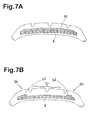
- In order to improve high-speed durability of a pneumatic tire especially a radial tire for passenger cars, as shown in Fig.7A, a single-layered full-width band (b1) over a breaker (a) is widely used. Here, a band means a cord layer whose cord angle is less than about 10 degrees usually less than 5 degrees with respect to the tire equator, and a breaker means a cord layer whose cord angle is more than 10 degrees usually more than 15 degrees.
- Such a single-layered full-width band (b1) can reduce a road noise around a frequency of 250 Hz heard on the inside of a vehicle during running. By using a higher tensile modulus cord in the band (b1), such a road noise may be reduced more, but a pass-by noise heard on the outside of a vehicle during running tends to increase. It is effectual in reducing the pass-by noise to use axially spaced edge bands (b2) on the edge portions of a breaker (a) as shown in Fig.7B. Such axially spaced edge bands (b2) however, tend to increase the rolling resistance of the tire.
- DE-A-195 09 824 discloses a pneumatic tire according to the precharacterizing portion of claim 1 and having a cover layer disposed radially outward of a belt. The cover layer is made of cords being hardly extensible in shoulder areas of the tire, and made of cords being extensible at a certain degree in a central area between these shoulder areas.
- US-A-4 407 347 discloses a radial ply pneumatic tire with a tread reinforcement in a crown region of the tire. This annular reinforcement includes superimposed layers of tire cord fabric with the cords in these layers being oriented to form an angle with the equatorial plane of the tire of between 15 and 25 degrees.
- It is therefore an object of the present invention to provide a pneumatic tire in which the rolling resistance and tire noise such as road noise and pass-by noise are improved.
- According to the present invention this object is achieved by a pneumatic tire with the features of claim 1.
- Embodiments of the present invention will now be described in detail in accordance with the accompanying drawings.
- Fig.1 is a cross sectional view of a radial tire according to the present invention.
- Figs.2A and 2B are perspective views of a rubber tape in which cords are embedded and a rubber coated single cord, respectively, which can be used to make a band.
- Figs.3, 4 and 5 each show an example structure of the band.
- Figs.6A, 6B, 6C and 6D show band structures used in the undermentioned comparison tests.
- Figs.7A and 7B shows band structures in the prior arts.
- In the drawings, pneumatic tire 1 according to the present invention comprises a tread portion 2, a pair of sidewall portions 3, a pair of
bead portions 4, acarcass 6 extending between thebead portions 4, abreaker 7 disposed radially outside thecarcass 6 in the tread portion 2, and aband 9 disposed on the radially outside of thebreaker 7. The tread portion 2 is provided with tread grooves G which are circumferentially continuously extending grooves and/or circumferentially extending discontinuous grooves. - The tire 1 in this example is a passenger car radial tire having a relatively low aspect ratio of 60 %. The aspect ratio is measured under a normally inflated unloaded state. The normally inflated unloaded state is such that the tire is mounted on a standard rim and inflated to a standard load but loaded with no tire load. The undermentioned tread width is the maximum axial width between the edges of the ground contacting area of the tread portion 2 under a standard loaded condition in which the tire is mounted on the standard rim and inflated to the standard load and then loaded with a standard load. The standard rim is the "standard rim" specified in JATMA, the "Measuring Rim" in ETRTO, the "Design Rim" in TRA or the like. The standard pressure is the "maximum air pressure" in JATMA, the "Inflation Pressure" in ETRTO, the maximum pressure given in the "Tire Load Limits at Various Cold Inflation Pressures" table in TRA or the like. In case of passenger car tires, however, 180 kPa is used as the standard pressure. The standard load is the "maximum load capacity" in JATMA, the "Load Capacity" in ETRTO, the maximum value given in the above-mentioned table in TRA or the like.
- The
carcass 6 comprises at least one ply 6A of cords arranged radially at an angle of from 75 to 90 degrees with respect to the tire equator C, extending between thebead portions 4 through the tread portion 2 and sidewall portions 3, and turned up around thebead core 5 in eachbead portion 4 from the inside to the outside of the tire so as to form a pair of turnups 6b and a carcass main 6a therebetween. For the carcass cords, organic fiber cords, e.g. polyester, nylon, rayon, aramid and the like and steel cords can be used. In this example, thecarcass 6 is composed of a single ply 6A of polyester cords arranged radially at 90 degrees. - Between the carcass main 6a and turnup 6b in each of the bead portions, there is disposed a
bead apex 8 of hard rubber extending radially outwardly from thebead core 5 while tapering towards its radially outer end. - The
breaker 7 is composed of at least twocross plies 7A and 7B of cords laid parallel with each other at an angle of from 15 to 45 degrees with respect to the tire equator C. For the breaker cords, steel cords and high tensile modulus organic cords such as aramid, rayon and the like can be used. The width W of thebreaker 7 is set in a range of from 80 to 110 % of the above-mentioned tread width. In this example, steel cords are used, and the radiallyinner breaker ply 7A is wider than the radially outer ply 7B. The axial width W of thebreaker 7 is defined as the axial width between theaxial edges 7e of thewidest ply 7A. - The
band 9 includes a pair of axially spaced highmodulus edge bands 10a disposed on edge portions of thebreaker 7, and a low modulusmiddle band 10b disposed between the highmodulus edge bands 10a. - The
band breaker 7 so that the cord angle with respect to the tire equator becomes in a range of not more than 5 degrees. Theband single cord 11 coated with atopping rubber 12 as shown in Fig.2B or a plurality ofcords 11 which are laid side by side and embedded in thetopping rubber 12 into in a form of rubber tape as shown in Fig.2A. - The high
modulus edge band 10a is made of one or more high tensile modulus cords. On the other hand, the low modulusmiddle band 10b is made of one or more low tensile modulus cords having a tensile modulus lower than that of the high tensile modulus band cord. - As to the material of the high tensile modulus cords, polyethylene-2,6-naphthalate (PEN), aramid, polyparaphenylene benzobis oxazole (PBO), steel and the like cane be used. In addition to a cord made of a single material, a hybrid cord of two or more different organic filaments twisted together, for example PEN + aramid, aramid + PBO and the like may be also used. Preferably, an organic fiber cord having a 2% modulus MH of not less than 10000 N/ sq.mm, more preferably not less than 12000 N/sq.mm is used.
- The sectional area SH of the high tensile modulus cord is set in a range of not less than 0.05 (sq.mm), preferably not less than 0.08 (sq.mm), more preferably 0.13 to 0.35 (sq.mm).
- The cord count DH of the high tensile modulus cord(s) of the high
modulus edge bands 10a is set in a range of from 5 to 23 (/1cm), preferably 6 to 20 (/1cm), more preferably 7 to 17 (/lcm). - As to the material of the low tensile modulus cords, on the other hand, nylon, polyester, vinylon and the like can be used. Preferably, organic fiber cords having a 2% modulus ML of not more than 8000 N/sq.mm, more preferably in a range of from 1500 to 6000 N/sq.mm are used.
- The sectional area SL of the low tensile modulus cord i s set in a range of from 0.04 to 0.80 (sq.mm), preferably 0.08 to 0.54 (sq.mm).
- The cord count DL of the low tensile modulus band cord(s) in the low modulus
middle band 10b is set in a range of 6 to 20 (/1cm), preferably 7 to 17 (/lcm). - Here, the 2% modulus MH, ML of a band cord is the tensile modulus at 2% elongation of the cord measured according to the Japanese Industrial Standard - L1017, "Testing Methods for Chemical Fiber Tie Cords".
- In the example shown in Fig.1, the low modulus
middle band 10b substantially abuts the highmodulus edge bands 10a, whereby theband 9 as a whole covers the overall width of thebreaker 7. - Fig.3 shows a modification of the low
modulus middle band 10b, which is extended to the axial edges of the breaker to cover the overall width of the breaker. The highmodulus edge bands 10a are wound on the radially outside thereof. Thus, the band as a whole has a double layered structure in the tread shoulder portion. - Fig.4 shows another modification of the low
modulus middle band 10b, which is decreased in the width and the axial edges of the lowmodulus middle band 10b are spaced apart from the axially inner edges 10ai of the highmodulus edge bands 10a. - Fig.5 shows still another modification of the narrowed low
modulus middle band 10b shown in Fig.4, which is split into two axially spaced middle bands 10b1 and 10b2. - Although all of the above-mentioned
bands - In any case, it is preferable that a band exists beneath a circumferential groove G or the entire width of the circumferential groove G is crossed by the band. As a result, stress in the groove bottom can be mitigated and high-speed durability, a resistance to damage and the like can be improved. The axial edges of the
band 9 as whole which are usually the axially outer edges of the edge bands are substantially aligned with the axial edges of thebreaker 7 or positioned slightly axially outward thereof. - The axial width BW1 of each of the high
modulus edge bands 10a is set in a range of from 3 to 44 %, preferably 6 to 34 %, more preferably 15 to 28 % of the axial width W of thebreaker 7. The total axial width BW2 of the low modulusmiddle band 10b or bands 10b1 and 10b2 is set in a range of not less than 8 %, preferably not less than 20 %, more preferably not less than 50 % of the width W of thebreaker 7. The width BW2 may be increased up to about 100 % of the width W of thebreaker 7 as shown in Fig.3. Such widths W, BW1 and BW2 are measured under the above-mentioned normally inflated unloaded state of the tire. - In each of the high
modulus edge bands 10a, an elongation resistance index PH defined as MH×SH×DH/100 is set in a range of from 160 to 700, preferably 160 to 400, more preferably 180 to 350. - In the low modulus
middle band 10b, an elongation resistance index PL defined as ML × SL×DL/100 is set in a range of not less than 30 but less than 160, preferably in a range of from 30 to 120, more preferably in a range of from 50 to 100. - As described above, the unit of the 2% modulus MH, ML is N/sq.mm. The unit of the sectional area SH, SL is sq.mm. The cord count DH, DL is the count per a unit width of 1cm.
- The ratio (PH/PL) of the elongation resistance index PH to the elongation resistance index PL is preferably set in a range of from 2 to 5, preferably 2 to 3.
- Therefore, the reinforcement by the high
modulus edge bands 10a and low modulusmiddle band 10b is optimized between the tread crown portion and shoulder portion, and as a result, the road noise is reduced without deteriorating the pass-by noise and rolling resistance. - If the elongation resistance index PL is less than 30, the hoopping effect to the tread crown portion becomes insufficient and the rolling resistance increases. If the elongation resistance index PL is more than 160, the hoopping effect to the tread crown becomes excessive and the pass-by noise tends to increase.
- If the ratio (PH /PL) is more than 5, the rigidity difference between the tread crown and tread shoulder increases, and as a result, the rolling resistance tends to increase. If the ratio (PH /PL) is less than 2, the road noise or pass-by noise becomes worse.
- Test tires of size 195/60R15 91H (Rim size 15X6JJ) for passenger cars having the same structure shown in Fig.1 except for the band structure were made and tested for the road noise, pass-by noise and rolling resistance. The specifications of the band are shown in Table 1.
- A Japanese 2000 cc FF passenger car provided on all the four wheels with test tires (pressure 200 kPa) was run on an asphalt road having a smooth road surface at a speed of 50 km/hr, and a sound pressure level (dB) of 250 Hz was measured near the left ear of the driver using a 1/3 octave band pass filter. The results are indicated in Table 1 as a difference from Ref.1.
- According to the "Test Procedure for Tire Noise" specified in Japanese JASO-C606, a test car provided with test tires was coasted for 50 meters at a speed of 53 km/h in a straight test course (asphalt road) and the maximum noise sound level was measured with a microphone set at 1.2 meter height from the road surface and 7.5 meter sideways from the running center line. The results are indicated in Table 1 as a difference from Ref.1.
- Using a rolling resistance tester, the rolling resistance (N) of the test tire was measured under an inner pressure of 230 kPa, tire load of 4400 N and speed of 80 km/hr. Each measurement is divided by the tire load 4400 N and multiply by 104 and the obtained value is shown in Table 1 as a difference from Ref.1.

- As described above, according to the present invention, the pneumatic radial tire can be improved in the road noise without deteriorating the pass-by noise and rolling resistance.
- The present invention can be suitably applied to radial tires for passenger cars as above, but it may be also possible to apply the present invention to radial tires for light trucks, heavy duty radial tires and the like.
Claims (3)
- A pneumatic tire (1) comprising:a carcass (6) extending between bead portions (4) through a tread portion (2) and sidewall portions (3),a breaker (7) disposed radially outside a crown portion of the carcass (6),a pair of axially spaced high modulus edge bands (10a) disposed radially outward of edge portions of the breaker (7) and each made of one or more high modulus cords (11) having a sectional area SH and a 2% modulus MH and wound at a cord count DH,a low modulus middle band (10b) disposed radially outward of the breaker (7) between the high modulus edge bands (10a) and made of one or more low modulus cords (11) having a sectional area SL and a 2% modulus ML less than the 2% modulus MH and wound at a cord count DL,
characterized
in that the breaker (7) is made of cords laid at an angle of 15 to 40 degrees with respect to the tire equator,
in that an elongation resistance index PH of each of the high modulus edge bands (10a), which is defined as the product of the 2% modulus MH in N/mm2, the sectional area SH in mm2 and the cord count DH per 1 cm width divided by 100, is in a range of 160 to 700, and
in that an elongation resistance index PL of the low modulus middle band (10b), which is defined as the product of the 2% modulus ML in N/mm2, the sectional area SL in mm2 and the cord count DL per 1 cm width divided by 100, is in a range of not less than 30 but less than 160, and the ratio (PH/PL) of the elongation resistance index PH to the elongation resistance index PL is in a range of from 2 to 5. - The pneumatic tire (1) according to claim 1,
characterized
in that the axial width (BW1) of each of the high modulus edge bands (10a) is in a range of from 3 to 44% of the axial width (W) of the breaker (7). - The pneumatic tire according to claim 1 or 2,
characterized
in that the axial width (BW2) of the low modulus middle band (10b) is in a range of not less than 8% of the axial width (W) of the breaker (7).
Applications Claiming Priority (2)
| Application Number | Priority Date | Filing Date | Title |
|---|---|---|---|
| JP2000334957 | 2000-11-01 | ||
| JP2000334957A JP3993378B2 (en) | 2000-11-01 | 2000-11-01 | Pneumatic radial tire |
Publications (3)
| Publication Number | Publication Date |
|---|---|
| EP1203672A2 EP1203672A2 (en) | 2002-05-08 |
| EP1203672A3 EP1203672A3 (en) | 2003-04-16 |
| EP1203672B1 true EP1203672B1 (en) | 2006-02-01 |
Family
ID=18810780
Family Applications (1)
| Application Number | Title | Priority Date | Filing Date |
|---|---|---|---|
| EP01126034A Expired - Lifetime EP1203672B1 (en) | 2000-11-01 | 2001-10-31 | Pneumatic tire |
Country Status (4)
| Country | Link |
|---|---|
| US (1) | US6557605B2 (en) |
| EP (1) | EP1203672B1 (en) |
| JP (1) | JP3993378B2 (en) |
| DE (1) | DE60116943T2 (en) |
Families Citing this family (39)
| Publication number | Priority date | Publication date | Assignee | Title |
|---|---|---|---|---|
| JP4635366B2 (en) * | 2001-04-12 | 2011-02-23 | 横浜ゴム株式会社 | Pneumatic radial tire |
| EP1396355B1 (en) | 2001-06-13 | 2009-03-18 | Sumitomo Rubber Industries, Ltd. | Pneumatic radial tire |
| JP4318425B2 (en) * | 2002-03-20 | 2009-08-26 | 住友ゴム工業株式会社 | Pneumatic tire |
| JP4318419B2 (en) * | 2001-12-18 | 2009-08-26 | 住友ゴム工業株式会社 | Pneumatic radial tire |
| JP3950088B2 (en) | 2003-07-24 | 2007-07-25 | 住友ゴム工業株式会社 | Pneumatic radial tire |
| JP4723198B2 (en) * | 2004-03-22 | 2011-07-13 | 住友ゴム工業株式会社 | Pneumatic tire |
| JP3934623B2 (en) * | 2004-03-29 | 2007-06-20 | 住友ゴム工業株式会社 | Pneumatic tire |
| JP4586518B2 (en) * | 2004-12-01 | 2010-11-24 | 横浜ゴム株式会社 | Heavy duty pneumatic tire |
| JP4901144B2 (en) * | 2005-06-29 | 2012-03-21 | 株式会社ブリヂストン | Pneumatic tire |
| JP4897283B2 (en) * | 2005-12-12 | 2012-03-14 | 住友ゴム工業株式会社 | Pneumatic tire |
| JP2007196898A (en) * | 2006-01-27 | 2007-08-09 | Yokohama Rubber Co Ltd:The | Pneumatic radial tire |
| DE102006022670A1 (en) | 2006-05-16 | 2007-11-22 | Continental Aktiengesellschaft | Vehicle tires |
| JP5069029B2 (en) * | 2007-03-29 | 2012-11-07 | 住友ゴム工業株式会社 | Pneumatic tire |
| FR2916159B1 (en) * | 2007-05-14 | 2011-03-18 | Michelin Soc Tech | PNEUMATIC FOR HEAVY VEHICLES |
| JP4377934B2 (en) * | 2007-08-03 | 2009-12-02 | 住友ゴム工業株式会社 | Pneumatic tire |
| JP4377933B2 (en) * | 2007-08-03 | 2009-12-02 | 住友ゴム工業株式会社 | Pneumatic tire |
| JP5104130B2 (en) * | 2007-08-31 | 2012-12-19 | 横浜ゴム株式会社 | Pneumatic tire |
| RU2011108276A (en) * | 2008-08-04 | 2012-09-10 | Титан Интернешнл, Инк. (Us) | HIGH PERFORMANCE RADIAL TIRE WITH BREAKER WITH NYLON AND METAL CORDS |
| JP5293135B2 (en) * | 2008-12-12 | 2013-09-18 | 横浜ゴム株式会社 | Pneumatic radial tire |
| JP5353272B2 (en) * | 2009-02-02 | 2013-11-27 | 横浜ゴム株式会社 | Pneumatic radial tire |
| JP5353275B2 (en) * | 2009-02-03 | 2013-11-27 | 横浜ゴム株式会社 | Pneumatic radial tire |
| JP5321103B2 (en) * | 2009-02-05 | 2013-10-23 | 横浜ゴム株式会社 | Pneumatic tire |
| JP2012020673A (en) * | 2010-07-15 | 2012-02-02 | Bridgestone Corp | Pneumatic tire |
| JP4837054B2 (en) * | 2009-02-16 | 2011-12-14 | 株式会社ブリヂストン | Pneumatic tire |
| JP2010260410A (en) * | 2009-04-30 | 2010-11-18 | Bridgestone Corp | Tire |
| JP2011051445A (en) * | 2009-09-01 | 2011-03-17 | Yokohama Rubber Co Ltd:The | Pneumatic tire |
| CN102666133B (en) * | 2009-12-11 | 2015-06-24 | 倍耐力轮胎股份公司 | Tyre for a wheel of a heavy load vehicle |
| JP5707860B2 (en) * | 2010-10-28 | 2015-04-30 | 横浜ゴム株式会社 | Pneumatic tire |
| US9862232B2 (en) | 2011-05-31 | 2018-01-09 | Pirelli Tyre S.P.A. | Pneumatic tyre for heavy load vehicle wheels |
| JP6516952B2 (en) * | 2012-09-26 | 2019-05-22 | 株式会社ブリヂストン | Pneumatic tire |
| JP6286147B2 (en) * | 2013-07-29 | 2018-02-28 | 東洋ゴム工業株式会社 | Pneumatic tire |
| JP6348713B2 (en) | 2014-01-09 | 2018-06-27 | 住友ゴム工業株式会社 | Pneumatic tire |
| DE102014220518A1 (en) * | 2014-10-09 | 2016-04-14 | Continental Reifen Deutschland Gmbh | Pneumatic vehicle tire having a belt bandage |
| CN107415595A (en) * | 2017-09-14 | 2017-12-01 | 中策橡胶集团有限公司 | A kind of Pneumatic belt tire |
| DE102018206562A1 (en) * | 2018-04-27 | 2019-10-31 | Continental Reifen Deutschland Gmbh | Vehicle tires |
| US20210178820A1 (en) * | 2019-12-17 | 2021-06-17 | The Goodyear Tire & Rubber Company | Pneumatic tire |
| JP2021160669A (en) * | 2020-04-02 | 2021-10-11 | 住友ゴム工業株式会社 | Pneumatic tire |
| JP7362958B1 (en) | 2023-02-02 | 2023-10-17 | Toyo Tire株式会社 | pneumatic tires |
| JP7362956B1 (en) | 2023-02-02 | 2023-10-17 | Toyo Tire株式会社 | pneumatic tires |
Family Cites Families (7)
| Publication number | Priority date | Publication date | Assignee | Title |
|---|---|---|---|---|
| FR2379391A1 (en) * | 1977-02-07 | 1978-09-01 | Uniroyal | NEW PNEUMATIC BANDAGE WRAP REINFORCEMENT BELT FOR AUTOMOTIVE VEHICLE WHEEL AND WRAP WITH APPLICATION |
| AU625337B2 (en) * | 1989-05-31 | 1992-07-09 | Sp Reifenwerke Gmbh | Vehicle tyre |
| JPH07215011A (en) * | 1994-01-31 | 1995-08-15 | Bridgestone Corp | Pneumatic radial tire |
| DE19509824A1 (en) * | 1995-03-17 | 1996-09-19 | Sp Reifenwerke Gmbh | Pneumatic tyre breaker for light tyres |
| DE69509323T2 (en) * | 1994-08-23 | 1999-08-26 | Dunlop Gmbh | Pneumatic vehicle tires |
| DE19526408A1 (en) * | 1995-07-19 | 1997-01-23 | Sp Reifenwerke Gmbh | Pneumatic vehicle tires |
| JP3113592B2 (en) * | 1996-02-15 | 2000-12-04 | 住友ゴム工業株式会社 | Pneumatic radial tire |
-
2000
- 2000-11-01 JP JP2000334957A patent/JP3993378B2/en not_active Expired - Fee Related
-
2001
- 2001-10-31 DE DE60116943T patent/DE60116943T2/en not_active Expired - Lifetime
- 2001-10-31 EP EP01126034A patent/EP1203672B1/en not_active Expired - Lifetime
- 2001-11-01 US US09/985,140 patent/US6557605B2/en not_active Expired - Fee Related
Also Published As
| Publication number | Publication date |
|---|---|
| EP1203672A2 (en) | 2002-05-08 |
| JP2002137606A (en) | 2002-05-14 |
| JP3993378B2 (en) | 2007-10-17 |
| EP1203672A3 (en) | 2003-04-16 |
| DE60116943T2 (en) | 2006-10-26 |
| US20020079036A1 (en) | 2002-06-27 |
| DE60116943D1 (en) | 2006-04-13 |
| US6557605B2 (en) | 2003-05-06 |
Similar Documents
| Publication | Publication Date | Title |
|---|---|---|
| EP1203672B1 (en) | Pneumatic tire | |
| EP0887208B1 (en) | Pneumatic tyre | |
| EP1437236B1 (en) | Pneumatic tire | |
| US6237661B1 (en) | Run-flat tire with specified profile | |
| EP0790143B1 (en) | Pneumatic radial tyre | |
| EP1396355B1 (en) | Pneumatic radial tire | |
| AU2369899A (en) | Pneumatic tire | |
| EP0850788B1 (en) | Pneumatic radial tyre | |
| EP1207055B1 (en) | Pneumatic tire | |
| EP1197354B1 (en) | Pneumatic tire | |
| US6305452B1 (en) | Pneumatic radical tire for passenger car with carcass ply cut-out zone | |
| EP0596737B1 (en) | Radial tyre | |
| EP1172235B1 (en) | Pneumatic tire | |
| JP4486226B2 (en) | Pneumatic tire | |
| EP1120293B1 (en) | Pneumatic tyre | |
| JP3124851B2 (en) | Heavy duty tire | |
| EP0490596B1 (en) | Radial tyre | |
| US6296031B1 (en) | Pneumatic radial tire including a plurality of carcass plies with specified fold back portions | |
| EP1013477B1 (en) | Pneumatic tyre | |
| JP2714340B2 (en) | Pneumatic tire |
Legal Events
| Date | Code | Title | Description |
|---|---|---|---|
| PUAI | Public reference made under article 153(3) epc to a published international application that has entered the european phase |
Free format text: ORIGINAL CODE: 0009012 |
|
| AK | Designated contracting states |
Kind code of ref document: A2 Designated state(s): AT BE CH CY DE DK ES FI FR GB GR IE IT LI LU MC NL PT SE TR |
|
| AX | Request for extension of the european patent |
Free format text: AL;LT;LV;MK;RO;SI |
|
| PUAL | Search report despatched |
Free format text: ORIGINAL CODE: 0009013 |
|
| AK | Designated contracting states |
Designated state(s): AT BE CH CY DE DK ES FI FR GB GR IE IT LI LU MC NL PT SE TR |
|
| AX | Request for extension of the european patent |
Extension state: AL LT LV MK RO SI |
|
| 17P | Request for examination filed |
Effective date: 20030925 |
|
| AKX | Designation fees paid |
Designated state(s): DE FR GB |
|
| 17Q | First examination report despatched |
Effective date: 20040116 |
|
| GRAP | Despatch of communication of intention to grant a patent |
Free format text: ORIGINAL CODE: EPIDOSNIGR1 |
|
| GRAS | Grant fee paid |
Free format text: ORIGINAL CODE: EPIDOSNIGR3 |
|
| GRAA | (expected) grant |
Free format text: ORIGINAL CODE: 0009210 |
|
| AK | Designated contracting states |
Kind code of ref document: B1 Designated state(s): DE FR GB |
|
| REG | Reference to a national code |
Ref country code: GB Ref legal event code: FG4D |
|
| REF | Corresponds to: |
Ref document number: 60116943 Country of ref document: DE Date of ref document: 20060413 Kind code of ref document: P |
|
| ET | Fr: translation filed | ||
| PLBE | No opposition filed within time limit |
Free format text: ORIGINAL CODE: 0009261 |
|
| STAA | Information on the status of an ep patent application or granted ep patent |
Free format text: STATUS: NO OPPOSITION FILED WITHIN TIME LIMIT |
|
| 26N | No opposition filed |
Effective date: 20061103 |
|
| PGFP | Annual fee paid to national office [announced via postgrant information from national office to epo] |
Ref country code: GB Payment date: 20131030 Year of fee payment: 13 Ref country code: FR Payment date: 20131009 Year of fee payment: 13 |
|
| GBPC | Gb: european patent ceased through non-payment of renewal fee |
Effective date: 20141031 |
|
| PG25 | Lapsed in a contracting state [announced via postgrant information from national office to epo] |
Ref country code: GB Free format text: LAPSE BECAUSE OF NON-PAYMENT OF DUE FEES Effective date: 20141031 |
|
| REG | Reference to a national code |
Ref country code: FR Ref legal event code: ST Effective date: 20150630 |
|
| PG25 | Lapsed in a contracting state [announced via postgrant information from national office to epo] |
Ref country code: FR Free format text: LAPSE BECAUSE OF NON-PAYMENT OF DUE FEES Effective date: 20141031 |
|
| PGFP | Annual fee paid to national office [announced via postgrant information from national office to epo] |
Ref country code: DE Payment date: 20171025 Year of fee payment: 17 |
|
| REG | Reference to a national code |
Ref country code: DE Ref legal event code: R119 Ref document number: 60116943 Country of ref document: DE |
|
| PG25 | Lapsed in a contracting state [announced via postgrant information from national office to epo] |
Ref country code: DE Free format text: LAPSE BECAUSE OF NON-PAYMENT OF DUE FEES Effective date: 20190501 |