EP1203397B1 - Micromachined field asymmetric ion mobility filter and detection system - Google Patents
Micromachined field asymmetric ion mobility filter and detection system Download PDFInfo
- Publication number
- EP1203397B1 EP1203397B1 EP00946904A EP00946904A EP1203397B1 EP 1203397 B1 EP1203397 B1 EP 1203397B1 EP 00946904 A EP00946904 A EP 00946904A EP 00946904 A EP00946904 A EP 00946904A EP 1203397 B1 EP1203397 B1 EP 1203397B1
- Authority
- EP
- European Patent Office
- Prior art keywords
- flow path
- filter
- ion
- electrodes
- ions
- Prior art date
- Legal status (The legal status is an assumption and is not a legal conclusion. Google has not performed a legal analysis and makes no representation as to the accuracy of the status listed.)
- Expired - Lifetime
Links
- 238000001514 detection method Methods 0.000 title claims abstract description 13
- 150000002500 ions Chemical class 0.000 claims abstract description 85
- 239000000758 substrate Substances 0.000 claims abstract description 20
- 230000000737 periodic effect Effects 0.000 claims abstract description 9
- 125000006850 spacer group Chemical group 0.000 claims description 8
- 229910052710 silicon Inorganic materials 0.000 claims description 4
- 239000010703 silicon Substances 0.000 claims description 4
- 239000011521 glass Substances 0.000 claims description 3
- 238000010438 heat treatment Methods 0.000 claims description 2
- 238000001914 filtration Methods 0.000 claims 1
- 238000010926 purge Methods 0.000 claims 1
- 230000003134 recirculating effect Effects 0.000 claims 1
- 241000894007 species Species 0.000 description 11
- 238000001228 spectrum Methods 0.000 description 10
- CSCPPACGZOOCGX-UHFFFAOYSA-N Acetone Chemical compound CC(C)=O CSCPPACGZOOCGX-UHFFFAOYSA-N 0.000 description 8
- UHOVQNZJYSORNB-UHFFFAOYSA-N Benzene Chemical compound C1=CC=CC=C1 UHOVQNZJYSORNB-UHFFFAOYSA-N 0.000 description 6
- 230000035945 sensitivity Effects 0.000 description 6
- 230000005684 electric field Effects 0.000 description 5
- 238000000034 method Methods 0.000 description 4
- 238000010586 diagram Methods 0.000 description 3
- 238000004611 spectroscopical analysis Methods 0.000 description 3
- XUIMIQQOPSSXEZ-UHFFFAOYSA-N Silicon Chemical compound [Si] XUIMIQQOPSSXEZ-UHFFFAOYSA-N 0.000 description 2
- 238000004458 analytical method Methods 0.000 description 2
- 239000002360 explosive Substances 0.000 description 2
- PQPFFKCJENSZKL-UHFFFAOYSA-N pentan-3-amine Chemical compound CCC(N)CC PQPFFKCJENSZKL-UHFFFAOYSA-N 0.000 description 2
- BASFCYQUMIYNBI-UHFFFAOYSA-N platinum Chemical compound [Pt] BASFCYQUMIYNBI-UHFFFAOYSA-N 0.000 description 2
- 238000010408 sweeping Methods 0.000 description 2
- RTAQQCXQSZGOHL-UHFFFAOYSA-N Titanium Chemical compound [Ti] RTAQQCXQSZGOHL-UHFFFAOYSA-N 0.000 description 1
- 239000003570 air Substances 0.000 description 1
- 238000013459 approach Methods 0.000 description 1
- 239000003124 biologic agent Substances 0.000 description 1
- 230000000903 blocking effect Effects 0.000 description 1
- 230000015556 catabolic process Effects 0.000 description 1
- 239000013043 chemical agent Substances 0.000 description 1
- 239000003795 chemical substances by application Substances 0.000 description 1
- 238000006731 degradation reaction Methods 0.000 description 1
- 230000001419 dependent effect Effects 0.000 description 1
- 238000009792 diffusion process Methods 0.000 description 1
- 239000003814 drug Substances 0.000 description 1
- 229940079593 drug Drugs 0.000 description 1
- 230000000694 effects Effects 0.000 description 1
- 230000007613 environmental effect Effects 0.000 description 1
- 238000005530 etching Methods 0.000 description 1
- 239000012530 fluid Substances 0.000 description 1
- PCHJSUWPFVWCPO-UHFFFAOYSA-N gold Chemical compound [Au] PCHJSUWPFVWCPO-UHFFFAOYSA-N 0.000 description 1
- 239000010931 gold Substances 0.000 description 1
- 229910052737 gold Inorganic materials 0.000 description 1
- 238000002347 injection Methods 0.000 description 1
- 239000007924 injection Substances 0.000 description 1
- 238000001871 ion mobility spectroscopy Methods 0.000 description 1
- 238000004519 manufacturing process Methods 0.000 description 1
- 238000004949 mass spectrometry Methods 0.000 description 1
- 230000007935 neutral effect Effects 0.000 description 1
- 229910052697 platinum Inorganic materials 0.000 description 1
- 230000002285 radioactive effect Effects 0.000 description 1
- 238000000926 separation method Methods 0.000 description 1
- 239000000126 substance Substances 0.000 description 1
- 229910052719 titanium Inorganic materials 0.000 description 1
- 239000010936 titanium Substances 0.000 description 1
Images


Classifications
-
- H—ELECTRICITY
- H01—ELECTRIC ELEMENTS
- H01J—ELECTRIC DISCHARGE TUBES OR DISCHARGE LAMPS
- H01J49/00—Particle spectrometers or separator tubes
- H01J49/0013—Miniaturised spectrometers, e.g. having smaller than usual scale, integrated conventional components
- H01J49/0018—Microminiaturised spectrometers, e.g. chip-integrated devices, Micro-Electro-Mechanical Systems [MEMS]
-
- G—PHYSICS
- G01—MEASURING; TESTING
- G01N—INVESTIGATING OR ANALYSING MATERIALS BY DETERMINING THEIR CHEMICAL OR PHYSICAL PROPERTIES
- G01N27/00—Investigating or analysing materials by the use of electric, electrochemical, or magnetic means
- G01N27/62—Investigating or analysing materials by the use of electric, electrochemical, or magnetic means by investigating the ionisation of gases, e.g. aerosols; by investigating electric discharges, e.g. emission of cathode
- G01N27/622—Ion mobility spectrometry
- G01N27/624—Differential mobility spectrometry [DMS]; Field asymmetric-waveform ion mobility spectrometry [FAIMS]
Definitions
- This invention relates to a Field Asymmetric Ion Mobility (FAIM) filter, and more particularly, to a micromachined FAIM filter and spectrometer.
- FIM Field Asymmetric Ion Mobility
- Mass spectrometers are very sensitive, highly selective and provide a fast response time. Mass spectrometers, however, are large and require significant amounts of power to operate. They also require a powerful vacuum pump to maintain a high vacuum in order to isolate the ions from neutral molecules and permit detection of the selected ions, and are also very expensive.
- time of flight ion mobility spectrometry is the method currently implemented in most portable chemical weapons and explosives detectors.
- the detection is based not solely on mass, but on charge and cross-section of the molecule as well.
- molecular species identification is not as conclusive and accurate as the mass spectrometer.
- Time of flight ion mobility spectrometers typically have unacceptable resolution and sensitivity limitations when attempting to reduce their size, that is a drift tube length less than 2 inches. In time of flight ion mobility, the resolution is proportional to the length of the drift tube. The longer the tube the better the resolution, provided the drift tube is also wide enough to prevent all ions from being lost to the side walls due to diffusion.
- FAIM spectrometry was developed in the former Soviet Union in the 1980's. FAIM spectrometry allows a selected ion to pass through a filter while blocking the passage of undesirable ions.
- Conventional FAIM spectrometers are large and expensive, e.g., the entire device is nearly a cubic foot in size and costs over $25,000. These systems are not suitable for use in applications requiring small detectors. They are also relatively slow, taking as much as one minute to produce a complete spectrum of the sample gas, are difficult to manufacture and are not mass producible.
- the present invention provides a field asymmetric ion mobility system according to the characterising portion of claim 1.
- FAIM spectrometer 10 operates by drawing a gas, indicated by arrow 12, via pump 14, through inlet 16 into ionization region 18.
- the ionized gas is passed between parallel electrode plates 20 and 22, which comprise ion filter 24, following flow path 26.
- the gas ions pass between plates 20 and 22, they are exposed to an asymmetric oscillating electric field between electrode plates 20 and 22 induced by a voltage applied to the plates by voltage generator 28 in response to electronic controller 30
- Detector 32 includes a top electrode 33 at a predetermined voltage and a bottom electrode 35, typically at ground. Top electrode 33 deflects ions downward to electrode 35. However, either electrode may detect ions depending on the ion and the voltage applied to the electrodes. Moreover, multiple ions may be detected by using top electrode 33 as one detector and bottom electrode 35 as a second detector.
- Electronic controller 30 may include, for example, amplifier 34 and microprocessor 36. Amplifier 34 amplifies the output of detector 32, which is a function of the charge collected by detector 34, and provides the output to microprocessor 36 for analysis. Similarly, amplifier 34', shown in phantom, may be provided where electrode 33 is also utilized as a detector.
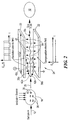
- ions 38, Fig. 2 pass through alternating asymmetric electric field 40, which is transverse to gas flow 12, electric field 40 causes the ions to "wiggle" along paths 42a, 42b and 42c.
- Field 40 is typically in the range of ⁇ (1000-2000) volts dc and has a maximum field strength of 40,000 V/cm. The path taken by a particular ion is a function of its mass, size, cross-section and charge. Once an ion reaches electrode 20 or 22, it is neutralized.
- a second, bias or compensation field 44 is concurrently induced between electrodes 20 and 22 by a bias voltage applied to plates 20 and 22, also by voltage generator 28, Fig. 1 , in response to microprocessor 36 to enable a preselected ion species to pass through filter 24 to detector 32.
- Compensation field 44 is a constant bias which offsets alternating asymmetric field 40 to allow the preselected ions, such as ion 38c to pass to detector 32.
- the output of FAIM spectrometer 10 is a measure of the amount of charge on detector 32 for a given bias voltage 44.
- the FAIM spectrometer according to the present invention requires typically less than thirty seconds and as little as one second to produce a complete spectrum for a given gas sample.
- the species to be detected can be varied to provide a complete spectrum of the gas sample. For example, with a bias voltage of -3.5 volts acetone was detected as demonstrated by concentration peaks 46, Fig. 3A in concentrations as low as 83 parts per billion. In contrast, at a bias voltage of - 6.5 volts, diethyl methyl amine, peaks 48, Fig. 3B , was detected in concentrations as low as 280 parts per billion.
- Spectrometer 10 includes spaced substrates 52 and 54, for example glass such as Pyrex@ available from Coming Glass, Coming, N.Y., and electrodes 20 and 22, which may be for example gold, titanium, or platinum, mounted or formed on substrates 52 and 54, respectively.
- Substrates 52 and 54 are separated by spacers 56a and 56b which may be formed by etching or dicing silicon wafer. The thickness of spacers 56a-b defines the distance between electrodes 20 and 22.
- spacers 56a-b typically ⁇ (10-1000 volts dc) transforms spacers 56a and 56b into electrodes which produce a confining electric field 58, which guides or confines the ions' paths to the center of flow path 26, Fig. 1 , in order to obtain a better sample spectrum.
- spacer electrodes 56a-b must be at the same voltage so as to "push" the ions to the center of flow path 26. This increases the sensitivity of the system by preserving more ions so that more ions strike detector 34. However, this is not a necessary limitation of the invention.
- controller 30, Fig. 1 may include current source 29, shown in phantom, which provides, in response to microprocessor 36, a current I to electrode plates 20 and 22 to heat the plates, removing accumulated molecules.
- current I may instead be applied to spacer electrodes 56a and 56 b, Fig. 4 , to heat flow path 26 and clean plates 20 and 22.
- Packaged FAIM spectrometer 10, Fig. 5 may be reduced in size to one inch by one inch by one inch.
- Pump 14 is mounted on substrate 52 for drawing a gas sample 12 into inlet 16. Clean dry air may be introduced into flow path 26, Fig. 1 , by recirculation pump 14a prior to or after ionization of the gas sample.
- Electronic controller 30 may be etched into silicon control layer 60 which combines with substrates 52 and 54 to form a housing for spectrometer 10. Substrates 52 and 54 and control layer 60 may be bonded together, for example, using anodic bonding, to provide an extremely small FAIM spectrometer.
- Micro pumps 14 and 14a provide a high volume throughput which further expedites the analysis of gas sample 12.
- Pumps 14 and 14a may be, for example, conventional miniature disk drive motors fitted with small centrifugal air compressor rotors or micromachined pumps, which produce flow rates of 1 to 4 liters per minute.
- Pump 14 is available from Sensidyne, Inc., Clearwater, Florida.
- FAIM spectrometer 10 may include filter array 62, a single inlet 16 and single flow path 26.
- Sample gas 12 is guided by confining electrodes 56a-h to filter array 62 after passing by ionization source 18, which may include an ultraviolet light source, a radioactive device or corona discharge device.
- Filter array 62 includes, for example, paired filter electrodes 20a-e and 22a-e and may simultaneously detect different ion species by applying a different compensation bias voltage 44, Fig.
- array 62 may include any number of filters depending on the size of the spectrometer.
- Detector array 64 which includes detectors 32a-e, detects multiple selected ion species simultaneously, thereby reduce the time necessary to obtain a spectrum of the gas sample 12.
- the electrode pairs share the same asymmetric periodic ac voltage 40.
- Clean dry air may be introduced into flow path 26 through clean air inlet 66 via recirculator pump 14a, Fig. 5 . Drawing in clean dry air assists in reducing the FAIM spectrometer's sensitivity to humidity. Moreover, if the spectrometer is operated without clean dry air and a known gas sample is introduced into the device, the device can be used as a humidity sensor since the resulting spectrum will change with moisture concentration from the standardized spectrum for the given sample.
- each filter 32a-e of filter array 62 may share the same flow path 26 so that each flow path has associated with it, for example, inlet 16a , ionization region 18a, confining electrodes 56a', 56b', ion filter electrode pair 20a, 22a, detector electrode pair 33a, 35a and exit port 68a.
- sample gas 12 enters sample inlet 16a, Fig. 8 , and is ionized by, for example, a corona discharge device 18a.
- the ionized sample is guided towards ion filter 24a by confining electrodes 56a.
- undesirable ions will be neutralized while selected ions will pass through filter 24a to be detected by detector 32a.
- a compensation bias voltage is not necessary to detect a selected specie or species of ion.
- Voltage generator 28 in response to control electronics 30 varies the duty cycle of asymmetric alternating voltage 40.
- the path of selected ion 32c may be controlled.
- the duty cycle of field 40 may be one quarter: 25% high, peak 70, and 75% low, valley 72, and ion 38c approaches plate 20 to be neutralized.
- detector 32 may be segmented.
- the individual ions 38c'-38c"" may be detected spatially, the ions having their trajectories 42c'-42c"" determined according to their size, charge and cross section.
- detector segment 32' will have one a concentration of one species of ion while detector segment 32" will have a different ion species concentration, increasing the spectrum resolution as each segment may detect a particular ion species.
Landscapes
- Chemical & Material Sciences (AREA)
- Physics & Mathematics (AREA)
- Analytical Chemistry (AREA)
- Spectroscopy & Molecular Physics (AREA)
- Biochemistry (AREA)
- Health & Medical Sciences (AREA)
- Life Sciences & Earth Sciences (AREA)
- Electrochemistry (AREA)
- Chemical Kinetics & Catalysis (AREA)
- General Health & Medical Sciences (AREA)
- General Physics & Mathematics (AREA)
- Immunology (AREA)
- Pathology (AREA)
- Other Investigation Or Analysis Of Materials By Electrical Means (AREA)
- Electron Tubes For Measurement (AREA)
- Investigating Or Analyzing Materials By The Use Of Electric Means (AREA)
- Measurement Of Radiation (AREA)
Abstract
Description
- This invention relates to a Field Asymmetric Ion Mobility (FAIM) filter, and more particularly, to a micromachined FAIM filter and spectrometer.
- The ability to detect and identify explosives, drugs, chemical and biological agents as well as air quality has become increasingly more critical given increasing terrorist and military activities and environmental concerns. Previous detection of such agents was accomplished with conventional mass spectrometers, time of flight ion mobility spectrometers and conventionally machined FAIM spectrometers.
- Mass spectrometers are very sensitive, highly selective and provide a fast response time. Mass spectrometers, however, are large and require significant amounts of power to operate. They also require a powerful vacuum pump to maintain a high vacuum in order to isolate the ions from neutral molecules and permit detection of the selected ions, and are also very expensive.
- Another spectrometric technique which is less complex is time of flight ion mobility spectrometry which is the method currently implemented in most portable chemical weapons and explosives detectors. The detection is based not solely on mass, but on charge and cross-section of the molecule as well. However, because of these different characteristics, molecular species identification is not as conclusive and accurate as the mass spectrometer. Time of flight ion mobility spectrometers typically have unacceptable resolution and sensitivity limitations when attempting to reduce their size, that is a drift tube length less than 2 inches. In time of flight ion mobility, the resolution is proportional to the length of the drift tube. The longer the tube the better the resolution, provided the drift tube is also wide enough to prevent all ions from being lost to the side walls due to diffusion. Thus, fundamentally, miniaturization of time of flight ion mobility systems leads to a degradation in system performance. While these devices are relatively inexpensive and reliable, they suffer from several limitations. First, the sample volume through the detector is small, so to increase spectrometer sensitivity either the detector electronics must have extremely high sensitivity, requiring expensive electronics, or a concentrator is required, adding to system complexity. In addition, a gate and gating electronics are usually needed to control the injection of ions into the drift tube.
- FAIM spectrometry was developed in the former Soviet Union in the 1980's. FAIM spectrometry allows a selected ion to pass through a filter while blocking the passage of undesirable ions. Conventional FAIM spectrometers are large and expensive, e.g., the entire device is nearly a cubic foot in size and costs over $25,000. These systems are not suitable for use in applications requiring small detectors. They are also relatively slow, taking as much as one minute to produce a complete spectrum of the sample gas, are difficult to manufacture and are not mass producible.
- Buryakov I A et al: "A new method of separation of multi-atomic ions by mobility at atmospheric pressure using a high-frequency amplitude-asymmetric strong electric field" International Journal of Mass Spectrometry and Ion Processes, Elsevier Scientific Publishing Co. Amsterdam, NL, vol. 128, 1993, pages 143-148; XP000865695 ISSN; 0168-1176 discloses a system having the features of the preamble of
claim 1. - The present invention provides a field asymmetric ion mobility system according to the characterising portion of
claim 1. - Optional features are recited in the dependent claims.
- Other objects, features and advantages will occur to those skilled in the art from the following description of a preferred embodiment and the accompanying drawings, in which:
-
Fig. 1 is a schematic block diagram of the micromachined filter and detection system according to the present invention; -
Fig. 2 is a schematic representation of the ions as they pass through the filter electrodes ofFig. 1 toward the detector; -
Fig. 3A is a graphical representation of the bias voltage required to detect acetone and the sensitivity obtainable; -
Fig. 3B is a representation, similar toFig. 3A , of the bias voltage required to detect Diethyl methyl amine; -
Fig. 4 is a cross sectional of the view of the spaced, micromachined filter according to the present invention; -
Fig. 5 is a three dimensional view of the packaged micromachined filter and detection system, including fluid flow pumps, demonstrating the miniaturized size which maybe realized; -
Fig. 6 is an exploded view of one embodiment according to the present invention in which an array of filters and detectors are disposed in a single flow path; -
Fig. 7 is an exploded view, similar toFig. 6 , in which the array of filters is stacked and one filter and detector is associated with a single flow path. -
Fig. 8 is a cross sectional representation of a single flow path of the arrayed filter and detector system ofFig. 7 ; -
Fig. 9 is graphical representation demonstrating simultaneous multiple detections of benzene and acetone; -
Fig. 10 is a schematic block diagram, similarFig. 1 , in which the filter is not compensated by a bias voltage and the duty cycle of the periodic voltage is instead varied to control the flow of ions through the filter; -
Fig. 11 is a graphical representation of an asymmetric periodic voltage having a varying duty cycle which is applied to the filter ofFig. 9 to filter selected ions without a bias voltage; and -
Fig. 12 is a schematic diagram of a filter and detector system in which the detector is segmented to spatially detect ions as they exit the filter. - FAIM
spectrometer 10,Fig. 1 , operates by drawing a gas, indicated byarrow 12, viapump 14, throughinlet 16 intoionization region 18. The ionized gas is passed betweenparallel electrode plates ion filter 24, followingflow path 26. As the gas ions pass betweenplates electrode plates voltage generator 28 in response toelectronic controller 30 - As ions pass through
filter 24, some are neutralized byplates detector 32.Detector 32 includes atop electrode 33 at a predetermined voltage and abottom electrode 35, typically at ground.Top electrode 33 deflects ions downward toelectrode 35. However, either electrode may detect ions depending on the ion and the voltage applied to the electrodes. Moreover, multiple ions may be detected by usingtop electrode 33 as one detector andbottom electrode 35 as a second detector.Electronic controller 30 may include, for example,amplifier 34 andmicroprocessor 36.Amplifier 34 amplifies the output ofdetector 32, which is a function of the charge collected bydetector 34, and provides the output tomicroprocessor 36 for analysis. Similarly, amplifier 34', shown in phantom, may be provided whereelectrode 33 is also utilized as a detector. - As
ions 38,Fig. 2 , pass through alternating asymmetricelectric field 40, which is transverse togas flow 12,electric field 40 causes the ions to "wiggle" alongpaths Field 40 is typically in the range of ± (1000-2000) volts dc and has a maximum field strength of 40,000 V/cm. The path taken by a particular ion is a function of its mass, size, cross-section and charge. Once an ion reacheselectrode compensation field 44, typically in the range of ± 2000 V/cm or ± 100 volts dc, is concurrently induced betweenelectrodes plates voltage generator 28,Fig. 1 , in response tomicroprocessor 36 to enable a preselected ion species to pass throughfilter 24 todetector 32.Compensation field 44 is a constant bias which offsets alternatingasymmetric field 40 to allow the preselected ions, such asion 38c to pass todetector 32. Thus, with the proper bias voltage, a particular species of ion will followpath 42c while undesirable ions will followpaths electrode plates - The output of
FAIM spectrometer 10 is a measure of the amount of charge ondetector 32 for a givenbias voltage 44. Thelonger filter 24 is set at a given compensation bias voltage, the more charge will accumulate ondetector 32. However, by sweepingcompensation voltage 44 over a predetermined voltage range, a complete spectrum forsample gas 12 can be achieved. The FAIM spectrometer according to the present invention requires typically less than thirty seconds and as little as one second to produce a complete spectrum for a given gas sample. - By varying
compensation bias voltage 44 the species to be detected can be varied to provide a complete spectrum of the gas sample. For example, with a bias voltage of -3.5 volts acetone was detected as demonstrated byconcentration peaks 46,Fig. 3A in concentrations as low as 83 parts per billion. In contrast, at a bias voltage of - 6.5 volts, diethyl methyl amine, peaks 48,Fig. 3B , was detected in concentrations as low as 280 parts per billion. -
Filter 24,Fig. 4 , is on the order of one inch in size.Spectrometer 10 includes spacedsubstrates electrodes substrates Substrates spacers spacers 56a-b defines the distance betweenelectrodes silicon spacers 56a-b, typically ± (10-1000 volts dc) transformsspacers electric field 58, which guides or confines the ions' paths to the center offlow path 26,Fig. 1 , in order to obtain a better sample spectrum. To confine the ions,spacer electrodes 56a-b must be at the same voltage so as to "push" the ions to the center offlow path 26. This increases the sensitivity of the system by preserving more ions so that more ions strikedetector 34. However, this is not a necessary limitation of the invention. - To maintain accurate and reliable operation of
spectrometer 10, neutralized ions which accumulate onelectrode plates heating flow path 26. For example,controller 30,Fig. 1 , may includecurrent source 29, shown in phantom, which provides, in response tomicroprocessor 36, a current I to electrodeplates spacer electrodes Fig. 4 , to heatflow path 26 andclean plates - Packaged
FAIM spectrometer 10,Fig. 5 , may be reduced in size to one inch by one inch by one inch.Pump 14 is mounted onsubstrate 52 for drawing agas sample 12 intoinlet 16. Clean dry air may be introduced intoflow path 26,Fig. 1 , byrecirculation pump 14a prior to or after ionization of the gas sample.Electronic controller 30 may be etched intosilicon control layer 60 which combines withsubstrates spectrometer 10.Substrates control layer 60 may be bonded together, for example, using anodic bonding, to provide an extremely small FAIM spectrometer. Micro pumps 14 and 14a provide a high volume throughput which further expedites the analysis ofgas sample 12.Pumps pump 14 is available from Sensidyne, Inc., Clearwater, Florida. - While the FAIM spectrometer according to the present invention quickly produces a spectrum for a particular gas sample, the time for doing so may be further reduced with an array of
filters 32.FAIM spectrometer 10,Fig. 6 , may includefilter array 62, asingle inlet 16 andsingle flow path 26.Sample gas 12 is guided by confiningelectrodes 56a-h to filterarray 62 after passing byionization source 18, which may include an ultraviolet light source, a radioactive device or corona discharge device.Filter array 62 includes, for example, pairedfilter electrodes 20a-e and 22a-e and may simultaneously detect different ion species by applying a differentcompensation bias voltage 44,Fig. 2 , to each electrode pair and sweeping each electrode pair over a different voltage range greatly reducing the sweep time. However,array 62 may include any number of filters depending on the size of the spectrometer. Detector array 64, which includesdetectors 32a-e, detects multiple selected ion species simultaneously, thereby reduce the time necessary to obtain a spectrum of thegas sample 12. The electrode pairs share the same asymmetricperiodic ac voltage 40. - Clean dry air may be introduced into
flow path 26 throughclean air inlet 66 viarecirculator pump 14a,Fig. 5 . Drawing in clean dry air assists in reducing the FAIM spectrometer's sensitivity to humidity. Moreover, if the spectrometer is operated without clean dry air and a known gas sample is introduced into the device, the device can be used as a humidity sensor since the resulting spectrum will change with moisture concentration from the standardized spectrum for the given sample. - However, rather than each
filter 32a-e offilter array 62 sharing thesame flow path 26,individual flow paths 26a-e,Fig. 7 , may be provided so that each flow path has associated with it, for example,inlet 16a ,ionization region 18a, confiningelectrodes 56a', 56b', ionfilter electrode pair detector electrode pair port 68a. - In operation,
sample gas 12 enterssample inlet 16a,Fig. 8 , and is ionized by, for example, acorona discharge device 18a. The ionized sample is guided towardsion filter 24a by confiningelectrodes 56a. As ions pass betweenion filter electrodes filter 24a to be detected bydetector 32a. - As shown in
Fig. 9 , multiple, simultaneous detections were made of Benzene, peaks 50 and acetone peaks 51, demonstrating the advantage of the arrayed filters and detectors according to the present invention. - It has also been found that a compensation bias voltage is not necessary to detect a selected specie or species of ion. By varying the duty cycle of the asymmetric periodic voltage applied to
electrodes filter 24,Fig. 10 , there is no need to apply a constant bias voltage to plateelectrodes Voltage generator 28, in response to controlelectronics 30 varies the duty cycle of asymmetric alternatingvoltage 40. By varying the duty cycle ofperiodic voltage 40,Fig. 11 , the path of selectedion 32c may be controlled. As an example, rather than a limitation, the duty cycle offield 40 may be one quarter: 25% high,peak 70, and 75% low,valley 72, andion 38c approachesplate 20 to be neutralized. However, by varying the duty cycle ofvoltage 40a to 40%,peak 70a,ion 38c passes throughplates field 40, an ion's path may be controlled without the need of a bias voltage. - To improve FAIM spectrometry resolution even further,
detector 32,Fig. 12 , may be segmented. Thus, as ions pass throughfilter 24 betweenfilter electrodes individual ions 38c'-38c"" may be detected spatially, the ions having theirtrajectories 42c'-42c"" determined according to their size, charge and cross section. Thusdetector segment 32' will have one a concentration of one species of ion whiledetector segment 32" will have a different ion species concentration, increasing the spectrum resolution as each segment may detect a particular ion species. - Although specific features of the invention are shown in some drawings and not in others, this is for convenience only as each feature may be combined with any or all of the other features in accordance with the invention.
- Other embodiments will occur to those skilled in the art and are within the following claims:
Claims (23)
- A field asymmetric ion mobility system (10) comprising:a housing including a flow path between a sample input part (16) and an output part;an ion filter (24) disposed in the flow path, the filter including at least one pair of filter electrodes (20, 22), the filter electrodes (20, 22) opposing each other in the flow path; anda control part configured to apply an asymmetric periodic voltage to the ion filter electrodes (20, 22) for controlling the travel of ions through the filter (24), the system being characterized by:a planar chip assembly housing defining said flow path;the housing formed with at least a pair of substrates (52, 54); andat least one of said electrodes being micromachined on one of the substrates.
- The system of claim 1 wherein the substrates (52, 54) are glass.
- The system of claim 1 wherein the substrates (52, 54) are insulating and planar.
- The system of claim 1 wherein the flow path is non-conducting and has conducting electrodes defined thereon.
- The system of claim 1 wherein the substrate has insulating surfaces that define an electrically insulated flow path between the input part and the output part, the output part further comprising an ion detection region.
- The system of claim 5 wherein the output part further includes a detector (32) for detecting ions in the flow path.
- The system of claim 5 wherein the ion detection region further includes at least a pair of detector electrodes (33, 35) disposed in the flow path, one electrode formed on each substrate, for detection of ions in the flow path.
- The system of claim 7 wherein the control part (30) is further configured to simultaneously independently enable detection of different ion species, the detected ions being representative of different detected ion species simultaneously by the detector electrodes.
- The system of claim 7 wherein the control part (30) defines electronic leads for applying signals to the electrodes.
- The system of claim 1 further comprising a source of ionized gas at the input part (16), a pump coupled to the substrate and communicating with the flow path for driving of the ionized gas from the source to the output part.
- The system of claim 1 further comprising a recirculation pump (14a) coupled to the substrate and communicating with the flow path for recirculating gas in the flow path.
- The system of claim 1 further comprising a heater, in the flow path, for heating the flow path and purging neutralized ions.
- The system of claim 1 wherein the substrates are planar and extend to define the housing along the flow path
- The system of claim 1 wherein the substrates are separated by a spacer.
- The system of claim 1 further comprising an ion source for the input of ions into the flow path, the substrates forming an integral insulated housing along the flow axis, the housing holding the ion source, ion filter, electronics part and output part in fixed relationship to the flow path axis.
- The system of claim 15 wherein the control part (30) includes an electrical connection for connection of the electrodes (20,22) to an amplifier (34).
- The system of claim 16 wherein a controller is defined within the housing for controlling ion filtering.
- The system of claim 1, wherein the control part (30) applies a DC bias voltage and the periodic voltage across the ion filter electrodes (20, 22) for controlling the paths of ions through the filter (24).
- The system of claim 1 wherein the control part further comprises a drive circuit for selectively adjusting the duty cycle of the periodic voltage or a DC bias voltage to target a selected species of ion to be passed by the filter.
- The system of claim 1 wherein the substrates are planar and have at least insulated surfaces along the flow path between the filter electrodes and the output part.
- The system of claim 18 wherein the control part (30) is further configured sweep at least one of the applied voltages through a predetermined range according to the species being filtered.
- The system of claim 14 wherein the spacer extends along the flow path between a sample inlet and an outlet.
- The system of claim 14 wherein the spacer is silicon and defines confining electrodes in the flow path, further including a detector downstream from the ion filter for detecting ions traveling from the filter under the control of the confining electrodes.
Applications Claiming Priority (3)
| Application Number | Priority Date | Filing Date | Title |
|---|---|---|---|
| US358312 | 1989-05-26 | ||
| US09/358,312 US6495823B1 (en) | 1999-07-21 | 1999-07-21 | Micromachined field asymmetric ion mobility filter and detection system |
| PCT/US2000/017971 WO2001008197A1 (en) | 1999-07-21 | 2000-06-29 | Micromachined field asymmetric ion mobility filter and detection system |
Related Child Applications (1)
| Application Number | Title | Priority Date | Filing Date |
|---|---|---|---|
| EP10184775.4 Division-Into | 2010-09-30 |
Publications (3)
| Publication Number | Publication Date |
|---|---|
| EP1203397A1 EP1203397A1 (en) | 2002-05-08 |
| EP1203397A4 EP1203397A4 (en) | 2005-12-28 |
| EP1203397B1 true EP1203397B1 (en) | 2011-08-10 |
Family
ID=23409170
Family Applications (1)
| Application Number | Title | Priority Date | Filing Date |
|---|---|---|---|
| EP00946904A Expired - Lifetime EP1203397B1 (en) | 1999-07-21 | 2000-06-29 | Micromachined field asymmetric ion mobility filter and detection system |
Country Status (8)
| Country | Link |
|---|---|
| US (1) | US6495823B1 (en) |
| EP (1) | EP1203397B1 (en) |
| JP (5) | JP5015395B2 (en) |
| CN (1) | CN100358081C (en) |
| AT (1) | ATE520145T1 (en) |
| AU (1) | AU6058900A (en) |
| CA (1) | CA2379502A1 (en) |
| WO (1) | WO2001008197A1 (en) |
Families Citing this family (126)
| Publication number | Priority date | Publication date | Assignee | Title |
|---|---|---|---|---|
| US6504149B2 (en) | 1998-08-05 | 2003-01-07 | National Research Council Canada | Apparatus and method for desolvating and focussing ions for introduction into a mass spectrometer |
| US7157700B2 (en) | 2001-06-30 | 2007-01-02 | Sionex Corporation | System for collection of data and identification of unknown ion species in an electric field |
| US6815669B1 (en) | 1999-07-21 | 2004-11-09 | The Charles Stark Draper Laboratory, Inc. | Longitudinal field driven ion mobility filter and detection system |
| US7148477B2 (en) * | 1999-07-21 | 2006-12-12 | Sionex Corporation | System for trajectory-based ion species identification |
| US6815668B2 (en) | 1999-07-21 | 2004-11-09 | The Charles Stark Draper Laboratory, Inc. | Method and apparatus for chromatography-high field asymmetric waveform ion mobility spectrometry |
| US7098449B1 (en) | 1999-07-21 | 2006-08-29 | The Charles Stark Draper Laboratory, Inc. | Spectrometer chip assembly |
| US7057168B2 (en) * | 1999-07-21 | 2006-06-06 | Sionex Corporation | Systems for differential ion mobility analysis |
| US6512224B1 (en) | 1999-07-21 | 2003-01-28 | The Charles Stark Draper Laboratory, Inc. | Longitudinal field driven field asymmetric ion mobility filter and detection system |
| US7399958B2 (en) | 1999-07-21 | 2008-07-15 | Sionex Corporation | Method and apparatus for enhanced ion mobility based sample analysis using various analyzer configurations |
| US6495823B1 (en) * | 1999-07-21 | 2002-12-17 | The Charles Stark Draper Laboratory, Inc. | Micromachined field asymmetric ion mobility filter and detection system |
| US6806463B2 (en) | 1999-07-21 | 2004-10-19 | The Charles Stark Draper Laboratory, Inc. | Micromachined field asymmetric ion mobility filter and detection system |
| US7129482B2 (en) | 1999-07-21 | 2006-10-31 | Sionex Corporation | Explosives detection using differential ion mobility spectrometry |
| US7005632B2 (en) * | 2002-04-12 | 2006-02-28 | Sionex Corporation | Method and apparatus for control of mobility-based ion species identification |
| US6690004B2 (en) * | 1999-07-21 | 2004-02-10 | The Charles Stark Draper Laboratory, Inc. | Method and apparatus for electrospray-augmented high field asymmetric ion mobility spectrometry |
| AU2001239076A1 (en) * | 2000-03-14 | 2001-09-24 | National Research Council Canada | Tandem high field asymmetric waveform ion mobility spectrometry (faims)/ion mobility spectrometry |
| WO2001069219A2 (en) * | 2000-03-14 | 2001-09-20 | National Research Council Canada | Faims apparatus and method with laser-based ionization source |
| RU2278612C2 (en) * | 2000-07-14 | 2006-06-27 | Лайфскен, Инк. | Immune sensor |
| WO2002083276A1 (en) * | 2001-04-17 | 2002-10-24 | The Charles Stark Draper Laboratory, Inc. | Methods and apparatus for electrospray-augmented high field asymmetric ion mobility spectrometry |
| US6642526B2 (en) * | 2001-06-25 | 2003-11-04 | Ionfinity Llc | Field ionizing elements and applications thereof |
| EP2386852B1 (en) * | 2001-06-30 | 2019-08-28 | DH Technologies Development Pte. Ltd. | Identification of unknown components in a sample using a field asymmetric waveform ion mobility spectrometer (FAIMS), which enables simultaneous detection of positive and negative ions |
| US7119328B2 (en) * | 2001-06-30 | 2006-10-10 | Sionex Corporation | System for DMS peak resolution |
| US7274015B2 (en) * | 2001-08-08 | 2007-09-25 | Sionex Corporation | Capacitive discharge plasma ion source |
| US7091481B2 (en) | 2001-08-08 | 2006-08-15 | Sionex Corporation | Method and apparatus for plasma generation |
| US6727496B2 (en) * | 2001-08-14 | 2004-04-27 | Sionex Corporation | Pancake spectrometer |
| US6987262B2 (en) * | 2002-02-08 | 2006-01-17 | Ionalytics Corporation | FAIMS apparatus and method for detecting trace amounts of a vapour in a carrier gas |
| US7026612B2 (en) * | 2002-02-08 | 2006-04-11 | Ionalytics Corporation | FAIMS apparatus and method using carrier gases that contain a trace amount of a dopant species |
| US7005633B2 (en) * | 2002-02-08 | 2006-02-28 | Ionalytics Corporation | Method and apparatus for desolvating ions for introduction into a FAIMS analyzer region |
| WO2003067244A2 (en) * | 2002-02-08 | 2003-08-14 | Ionalytics Corporation | Faims with non-destructive detection of selectively transmitted ions |
| US7122794B1 (en) | 2002-02-21 | 2006-10-17 | Sionex Corporation | Systems and methods for ion mobility control |
| US20060134713A1 (en) * | 2002-03-21 | 2006-06-22 | Lifescan, Inc. | Biosensor apparatus and methods of use |
| US6630662B1 (en) * | 2002-04-24 | 2003-10-07 | Mds Inc. | Setup for mobility separation of ions implementing an ion guide with an axial field and counterflow of gas |
| US7687276B2 (en) * | 2002-05-30 | 2010-03-30 | Massachusetts Institute Of Technology | Method of detecting analyte vaporized from sample with low-power UV radiation |
| US7095019B1 (en) | 2003-05-30 | 2006-08-22 | Chem-Space Associates, Inc. | Remote reagent chemical ionization source |
| EP1539333B1 (en) | 2002-07-25 | 2014-10-15 | Dh Technologies Development Pte. Ltd. | Method and apparatus for control of mobility-based ion species identification |
| DE20380355U1 (en) * | 2002-09-03 | 2006-06-01 | Micromass Uk Ltd. | mass spectrometry |
| US7358504B2 (en) * | 2002-09-25 | 2008-04-15 | Thermo Finnigan Llc | FAIMS apparatus and method for separating ions |
| US7378651B2 (en) * | 2002-09-25 | 2008-05-27 | Thermo Finnigan Llc | High field asymmetric waveform ion mobility spectrometer FAIMS |
| AU2003298597A1 (en) * | 2002-10-12 | 2004-05-25 | Sionex Corporation | NOx MONITOR USING DIFFERENTIAL MOBILITY SPECTROMETRY |
| US6794647B2 (en) * | 2003-02-25 | 2004-09-21 | Beckman Coulter, Inc. | Mass analyzer having improved mass filter and ion detection arrangement |
| WO2004081527A2 (en) * | 2003-03-10 | 2004-09-23 | Sionex Corporation | Systems for differential ion mobility analysis |
| US7470898B2 (en) * | 2003-04-01 | 2008-12-30 | The Charles Stark Draper Laboratory, Inc. | Monitoring drinking water quality using differential mobility spectrometry |
| WO2004090534A1 (en) * | 2003-04-01 | 2004-10-21 | The Charles Stark Draper Laboratory, Inc. | Non-invasive breath analysis using field asymmetric ion mobility spectrometry |
| US6949741B2 (en) | 2003-04-04 | 2005-09-27 | Jeol Usa, Inc. | Atmospheric pressure ion source |
| WO2004097396A1 (en) * | 2003-04-24 | 2004-11-11 | Sionex Corporation | Apparatus and method for controlling ion behavior in ion mobility spectrometry |
| CA2472492A1 (en) * | 2003-06-27 | 2004-12-27 | Ionalytics Corporation | Method of separating ions |
| US7223970B2 (en) * | 2003-09-17 | 2007-05-29 | Sionex Corporation | Solid-state gas flow generator and related systems, applications, and methods |
| CA2547389A1 (en) * | 2003-11-25 | 2005-06-09 | Sionex Corporation | Mobility based apparatus and methods using dispersion characteristics, sample fragmentation, and/or pressure control to improve analysis of a sample |
| WO2005060696A2 (en) * | 2003-12-18 | 2005-07-07 | Sionex Corporation | Methods and apparatus for enhanced ion based sample detection using selective pre-separation and amplification |
| EP1733219A2 (en) | 2004-01-13 | 2006-12-20 | Sionex Corporation | Methods and apparatus for enhanced sample identification based on combined analytical techniques |
| WO2005069904A2 (en) * | 2004-01-16 | 2005-08-04 | The Regents Of The University Of California | Microfabricated device for selectively removing and analyzing airborne particulates |
| CA2493526C (en) * | 2004-01-22 | 2010-03-30 | Ionalytics Corporation | Apparatus and method for controllably affecting the temperature of faims components |
| US7135674B2 (en) * | 2004-01-22 | 2006-11-14 | Thermo Finnigan Llc | Method and apparatus for FAIMS with a laser-based ionization source |
| CA2554997A1 (en) * | 2004-02-02 | 2005-08-18 | Sionex Corporation | Compact sample analysis systems and related methods using combined chromatography and mobility spectrometry techniques |
| CA2499247A1 (en) * | 2004-03-03 | 2005-09-03 | Ionalytics Corporation | Method and apparatus for selecting inlets of a multiple inlet faims |
| EP1756561A1 (en) * | 2004-04-28 | 2007-02-28 | Sionex Corporation | System and method for ion species analysis with enhanced condition control and data interpretation using differential mobility spectrometers |
| CA2575556A1 (en) * | 2004-07-30 | 2006-02-09 | Sionex Corporation | Systems and methods for ion mobility control |
| US7388195B2 (en) * | 2004-09-30 | 2008-06-17 | Charles Stark Draper Laboratory, Inc. | Apparatus and systems for processing samples for analysis via ion mobility spectrometry |
| GB0424426D0 (en) | 2004-11-04 | 2004-12-08 | Micromass Ltd | Mass spectrometer |
| WO2006060807A1 (en) * | 2004-12-03 | 2006-06-08 | Sionex Corporation | Method and apparatus for enhanced ion based sample filtering and detection |
| DE102005007746B4 (en) * | 2005-02-18 | 2009-01-08 | Dräger Safety AG & Co. KGaA | Ion mobility spectrometer with parallel drift gas and ion carrier gas flow |
| GB0504361D0 (en) * | 2005-03-03 | 2005-04-06 | Smiths Group Plc | Detection apparatus |
| US7170053B2 (en) * | 2005-03-31 | 2007-01-30 | Battelle Memorial Institute | Method and apparatus for ion mobility spectrometry with alignment of dipole direction (IMS-ADD) |
| WO2006119167A1 (en) * | 2005-04-29 | 2006-11-09 | Sionex Corporation | Compact gas chromatography and ion mobility based sample analysis systems, methods, and devices |
| US7138626B1 (en) | 2005-05-05 | 2006-11-21 | Eai Corporation | Method and device for non-contact sampling and detection |
| US7312444B1 (en) | 2005-05-24 | 2007-12-25 | Chem - Space Associates, Inc. | Atmosperic pressure quadrupole analyzer |
| US7568401B1 (en) | 2005-06-20 | 2009-08-04 | Science Applications International Corporation | Sample tube holder |
| DE102005031048A1 (en) * | 2005-07-02 | 2007-01-04 | Dräger Safety AG & Co. KGaA | Ion mobility spectrometer uses unidirectional drift with larger dominant drift gas flow before detector electrode in separation area |
| US7579589B2 (en) | 2005-07-26 | 2009-08-25 | Sionex Corporation | Ultra compact ion mobility based analyzer apparatus, method, and system |
| GB0808344D0 (en) * | 2008-05-08 | 2008-06-18 | Owlstone Ltd | Sensor |
| GB0520397D0 (en) * | 2005-10-07 | 2005-11-16 | Smiths Group Plc | Vapour generators |
| US7573028B2 (en) * | 2005-10-26 | 2009-08-11 | Owlstone Nanotech, Inc. | Ion drive and odor emitter |
| US7576322B2 (en) | 2005-11-08 | 2009-08-18 | Science Applications International Corporation | Non-contact detector system with plasma ion source |
| US7727206B2 (en) * | 2005-12-27 | 2010-06-01 | Gorres Geoffrey H | Device for monitoring a patient for a urinary tract infection |
| WO2007120373A2 (en) * | 2006-01-26 | 2007-10-25 | Sionex Corporation | Differential mobility spectrometer analyzer and pre-filter apparatus, methods and systems |
| US7964017B2 (en) * | 2006-05-05 | 2011-06-21 | General Dynamics Armament And Technical Products, Inc. | Systems and methods for controlling moisture level in a gas |
| US7714277B2 (en) * | 2006-07-20 | 2010-05-11 | Owlstone Nanotech, Inc. | Smart FAIMS sensor |
| US20080017790A1 (en) * | 2006-07-20 | 2008-01-24 | Owlstone Nanotech Inc. | Smart FAIMS sensor |
| US8217344B2 (en) | 2007-02-01 | 2012-07-10 | Dh Technologies Development Pte. Ltd. | Differential mobility spectrometer pre-filter assembly for a mass spectrometer |
| EP2126961B1 (en) * | 2007-02-24 | 2014-06-18 | Sociedad Europea De Analisis Diferencial De Movilidad S.L. | Method to accurately discriminate gas phase ions with several filtering devices in tandem |
| US20100120073A1 (en) * | 2007-05-08 | 2010-05-13 | Superior Medical Llc | Methods and devices for detecting organisms causing urinary tract infections |
| US7963146B2 (en) | 2007-05-14 | 2011-06-21 | General Dynamics Armament And Technical Products, Inc. | Method and system for detecting vapors |
| US8123396B1 (en) | 2007-05-16 | 2012-02-28 | Science Applications International Corporation | Method and means for precision mixing |
| US7863562B2 (en) * | 2007-06-22 | 2011-01-04 | Shimadzu Corporation | Method and apparatus for digital differential ion mobility separation |
| US8173959B1 (en) | 2007-07-21 | 2012-05-08 | Implant Sciences Corporation | Real-time trace detection by high field and low field ion mobility and mass spectrometry |
| US8008617B1 (en) | 2007-12-28 | 2011-08-30 | Science Applications International Corporation | Ion transfer device |
| DE102008005281B4 (en) | 2008-01-19 | 2014-09-18 | Airsense Analytics Gmbh | Method and device for the detection and identification of gases |
| DE102008006208B4 (en) | 2008-01-26 | 2016-05-04 | Dräger Safety AG & Co. KGaA | Device for gas analysis |
| US7851745B2 (en) * | 2008-12-12 | 2010-12-14 | Thermo Finnigan Llc | Flat plate FAIMS with lateral ion focusing |
| US8071957B1 (en) | 2009-03-10 | 2011-12-06 | Science Applications International Corporation | Soft chemical ionization source |
| WO2010120193A1 (en) * | 2009-04-12 | 2010-10-21 | Lely Patent N.V. | Sensing techniques for on-farm analysis of milk components |
| WO2011045891A1 (en) * | 2009-10-13 | 2011-04-21 | 株式会社日立製作所 | Ion detecting device |
| US8143591B2 (en) * | 2009-10-26 | 2012-03-27 | Peter Gefter | Covering wide areas with ionized gas streams |
| PL218395B1 (en) * | 2011-05-17 | 2014-11-28 | Wojskowy Inst Chemii I Radiometrii | Ion mobility spectrometer chamber |
| US8502138B2 (en) * | 2011-07-29 | 2013-08-06 | Sharp Kabushiki Kaisha | Integrated ion mobility spectrometer |
| US9366649B2 (en) | 2012-03-29 | 2016-06-14 | Owlstone Nanotech Inc | Field asymmetric ion mobility spectrometry system |
| US9302271B2 (en) | 2012-07-04 | 2016-04-05 | Hitachi, Ltd. | Ion mobility separation device |
| US8809769B2 (en) * | 2012-11-29 | 2014-08-19 | Bruker Daltonics, Inc. | Apparatus and method for cross-flow ion mobility spectrometry |
| US9812311B2 (en) | 2013-04-08 | 2017-11-07 | Battelle Memorial Institute | Ion manipulation method and device |
| US8835839B1 (en) * | 2013-04-08 | 2014-09-16 | Battelle Memorial Institute | Ion manipulation device |
| US10338028B2 (en) | 2013-07-19 | 2019-07-02 | Hitachi, Ltd. | Ion mobility separation device |
| CN104634703B (en) * | 2013-11-08 | 2019-01-25 | 郑秀惠 | Air ion Mobility Spectrum Analysis method and instrument |
| CN103675090A (en) * | 2013-12-23 | 2014-03-26 | 中国电子科技集团公司第四十九研究所 | Harmful gas detector with low detection limit |
| KR20160071873A (en) | 2014-12-12 | 2016-06-22 | 현대자동차주식회사 | Ion filter life perception device for fuel cell vehicle |
| US9704701B2 (en) | 2015-09-11 | 2017-07-11 | Battelle Memorial Institute | Method and device for ion mobility separations |
| CA3000341C (en) | 2015-10-07 | 2019-04-16 | Battelle Memorial Institute | Method and apparatus for ion mobility separations utilizing alternating current waveforms |
| WO2017090792A1 (en) * | 2015-11-26 | 2017-06-01 | 한국기초과학지원연구원 | Device for measuring ion mobility of hazardous material and method for acquiring reference data thereby |
| JP6330154B2 (en) | 2016-05-24 | 2018-05-30 | パナソニックIpマネジメント株式会社 | Field asymmetric ion mobility spectrometer and mixture separation method using the same |
| US10692710B2 (en) | 2017-08-16 | 2020-06-23 | Battelle Memorial Institute | Frequency modulated radio frequency electric field for ion manipulation |
| US10497552B2 (en) | 2017-08-16 | 2019-12-03 | Battelle Memorial Institute | Methods and systems for ion manipulation |
| GB2566326A (en) * | 2017-09-11 | 2019-03-13 | Owlstone Inc | Ion mobility filter |
| EP3692564A1 (en) | 2017-10-04 | 2020-08-12 | Battelle Memorial Institute | Methods and systems for integrating ion manipulation devices |
| GB2573483B (en) * | 2017-10-06 | 2022-05-11 | Owlstone Inc | Ion Mobility Filter |
| CN109655532A (en) * | 2017-10-12 | 2019-04-19 | 贵州中烟工业有限责任公司 | A kind of method of pair of cigarette taxonomic history |
| JP7102733B2 (en) | 2018-01-04 | 2022-07-20 | 株式会社リコー | Ion detector and electric field asymmetric waveform ion mobility spectroscopic analysis system |
| US10782265B2 (en) * | 2018-03-30 | 2020-09-22 | Sharp Kabushiki Kaisha | Analysis apparatus |
| JP2020020746A (en) * | 2018-08-03 | 2020-02-06 | 株式会社リコー | Detector |
| JP7255150B2 (en) * | 2018-11-30 | 2023-04-11 | 株式会社リコー | Dehumidifier and detector |
| JP7251307B2 (en) * | 2019-05-16 | 2023-04-04 | 株式会社リコー | Analysis system, fecal odor gas analysis system and breath gas analysis system |
| CN111044638A (en) * | 2019-12-31 | 2020-04-21 | 贵州中烟工业有限责任公司 | Method for classifying and identifying different varieties of flue-cured tobacco leaves |
| JP7018090B2 (en) * | 2020-04-08 | 2022-02-09 | 俊 保坂 | Ultra-small accelerator, ultra-small mass spectrometer and ion implanter |
| US11092569B1 (en) | 2020-07-05 | 2021-08-17 | Cannabix Technologies Inc. | Apparatus and methods for detection of molecules |
| EP3979298A1 (en) * | 2020-09-30 | 2022-04-06 | Infineon Technologies Austria AG | Device for controlling trapped ions and method of manufacturing the same |
| CN114361007A (en) * | 2020-10-13 | 2022-04-15 | 中国科学院大连化学物理研究所 | Multidimensional adjusting device for efficient ionization of single cells |
| WO2022102172A1 (en) * | 2020-11-12 | 2022-05-19 | シャープ株式会社 | Analysis device |
| WO2023167914A1 (en) | 2022-03-01 | 2023-09-07 | Arrowhead Center, Inc. | Apparatus and method for agricultural contaminant detection |
| CN115274396B (en) * | 2022-06-17 | 2024-01-02 | 东南大学 | Portable magnetic field enhanced ion mobility spectrometer and gas component detection method thereof |
Family Cites Families (52)
| Publication number | Priority date | Publication date | Assignee | Title |
|---|---|---|---|---|
| US2818507A (en) | 1946-03-22 | 1957-12-31 | Roy J Britten | Velocity selector method for the separation of isotopes |
| US2615135A (en) | 1950-06-20 | 1952-10-21 | Jr William E Glenn | Mass analyzing apparatus |
| US2919348A (en) | 1956-07-05 | 1959-12-29 | Bierman Aron | Device for the separation of gas ions |
| US3535512A (en) | 1966-07-21 | 1970-10-20 | Varian Associates | Double resonance ion cyclotron mass spectrometer for studying ion-molecule reactions |
| US3621240A (en) | 1969-05-27 | 1971-11-16 | Franklin Gro Corp | Apparatus and methods for detecting and identifying trace gases |
| US3619605A (en) | 1969-06-25 | 1971-11-09 | Phillips Petroleum Co | Mass spectrometer method and apparatus employing high energy metastable ions to generate sample ions |
| US3648046A (en) | 1970-05-18 | 1972-03-07 | Granville Phillips Co | Quadrupole gas analyzer comprising four flat plate electrodes |
| NL7415318A (en) | 1974-11-25 | 1976-05-28 | Philips Nv | WIENFILTER. |
| FR2363364A1 (en) | 1976-09-07 | 1978-03-31 | Thomson Csf | ISOTOPIC SEPARATION PROCESS AND INSTALLATION FOR ITS IMPLEMENTATION |
| US4163151A (en) | 1977-12-28 | 1979-07-31 | Hughes Aircraft Company | Separated ion source |
| SU966583A1 (en) | 1980-03-10 | 1982-10-15 | Предприятие П/Я А-1342 | Method of analysis of impurities in gases |
| US4315153A (en) | 1980-05-19 | 1982-02-09 | Hughes Aircraft Company | Focusing ExB mass separator for space-charge dominated ion beams |
| FR2514905A1 (en) | 1981-10-21 | 1983-04-22 | Commissariat Energie Atomique | DEVICE FOR MEASURING IONIC CURRENT PRODUCED BY ION BEAM |
| US4761545A (en) | 1986-05-23 | 1988-08-02 | The Ohio State University Research Foundation | Tailored excitation for trapped ion mass spectrometry |
| FI75055C (en) | 1986-06-03 | 1988-04-11 | Puumalaisen Tutkimuslaitos Oy | Method for observing gas content of ingredients. |
| SU1405489A1 (en) | 1986-11-03 | 1998-06-10 | И.А. Буряков | Method of analyzing traces of substances in gases |
| SU1412447A1 (en) | 1986-11-03 | 1998-06-20 | И.А. Буряков | Drift spectrometer to detect microimpurities of substances in gases |
| US4885500A (en) | 1986-11-19 | 1989-12-05 | Hewlett-Packard Company | Quartz quadrupole for mass filter |
| SU1485808A1 (en) | 1987-03-30 | 1998-06-10 | И.А. Буряков | Method of analyzing traces of substances in gases |
| JPH01260799A (en) * | 1988-04-12 | 1989-10-18 | Fujitsu Ltd | Plasma device |
| DE3914838A1 (en) | 1989-05-05 | 1990-11-08 | Spectrospin Ag | ION CYCLOTRON RESONANCE SPECTROMETER |
| US4931640A (en) | 1989-05-19 | 1990-06-05 | Marshall Alan G | Mass spectrometer with reduced static electric field |
| US5281494A (en) | 1990-05-04 | 1994-01-25 | Inco Limited | Nickel hydroxide |
| US5144127A (en) | 1991-08-02 | 1992-09-01 | Williams Evan R | Surface induced dissociation with reflectron time-of-flight mass spectrometry |
| WO1993005532A1 (en) | 1991-09-11 | 1993-03-18 | Sumitomo Electric Industries, Ltd. | Quadrupole electrode and manufacture thereof |
| DE4134212A1 (en) * | 1991-10-16 | 1993-04-22 | Leonhardt Juergen W Prof Dr | Micro-ionisation sensor to detect pollutants in air - comprises ion source, gas passage, ion path, control system, collector electrodes, amplifier and conductor system formed within cylindrical semiconductor element |
| US5298745A (en) | 1992-12-02 | 1994-03-29 | Hewlett-Packard Company | Multilayer multipole |
| US5492867A (en) | 1993-09-22 | 1996-02-20 | Westinghouse Elect. Corp. | Method for manufacturing a miniaturized solid state mass spectrograph |
| US5536939A (en) * | 1993-09-22 | 1996-07-16 | Northrop Grumman Corporation | Miniaturized mass filter |
| US5401963A (en) | 1993-11-01 | 1995-03-28 | Rosemount Analytical Inc. | Micromachined mass spectrometer |
| US5731228A (en) | 1994-03-11 | 1998-03-24 | Fujitsu Limited | Method for making micro electron beam source |
| US5420424A (en) * | 1994-04-29 | 1995-05-30 | Mine Safety Appliances Company | Ion mobility spectrometer |
| US5455417A (en) * | 1994-05-05 | 1995-10-03 | Sacristan; Emilio | Ion mobility method and device for gas analysis |
| KR0156602B1 (en) | 1994-07-08 | 1998-12-01 | 황해웅 | Ion mobility analyzer |
| US5654544A (en) | 1995-08-10 | 1997-08-05 | Analytica Of Branford | Mass resolution by angular alignment of the ion detector conversion surface in time-of-flight mass spectrometers with electrostatic steering deflectors |
| US5852302A (en) | 1996-01-30 | 1998-12-22 | Shimadzu Corporation | Cylindrical multiple-pole mass filter with CVD-deposited electrode layers |
| US5801379A (en) | 1996-03-01 | 1998-09-01 | Mine Safety Appliances Company | High voltage waveform generator |
| US5736739A (en) | 1996-04-04 | 1998-04-07 | Mine Safety Appliances Company | Recirculating filtration system for use with a transportable ion mobility spectrometer in gas chromatography applications |
| US5763876A (en) * | 1996-04-04 | 1998-06-09 | Mine Safety Appliances Company | Inlet heating device for ion mobility spectrometer |
| US5723861A (en) | 1996-04-04 | 1998-03-03 | Mine Safety Appliances Company | Recirculating filtration system for use with a transportable ion mobility spectrometer |
| JP2000509487A (en) * | 1996-04-04 | 2000-07-25 | マイン・セイフティ・アプライアンセス・カンパニー | Recirculating filtration device for use with a portable ion mobility analyzer |
| US5644131A (en) | 1996-05-22 | 1997-07-01 | Hewlett-Packard Co. | Hyperbolic ion trap and associated methods of manufacture |
| US6051832A (en) * | 1996-08-20 | 2000-04-18 | Graseby Dynamics Limited | Drift chambers |
| GB9617409D0 (en) * | 1996-08-20 | 1996-10-02 | Graseby Dynamics Ltd | Drift tubes |
| US6049052A (en) | 1997-06-03 | 2000-04-11 | California Institute Of Technology | Miniature micromachined quadrupole mass spectrometer array and method of making the same |
| AU7805498A (en) | 1997-06-03 | 1998-12-21 | California Institute Of Technology | Miniature micromachined quadrupole mass spectrometer array and method of making the same |
| US6157031A (en) | 1997-09-17 | 2000-12-05 | California Institute Of Technology | Quadropole mass analyzer with linear ion trap |
| US5965882A (en) * | 1997-10-07 | 1999-10-12 | Raytheon Company | Miniaturized ion mobility spectrometer sensor cell |
| US5789745A (en) | 1997-10-28 | 1998-08-04 | Sandia Corporation | Ion mobility spectrometer using frequency-domain separation |
| US6124592A (en) * | 1998-03-18 | 2000-09-26 | Technispan Llc | Ion mobility storage trap and method |
| AU5144399A (en) | 1998-08-05 | 2000-02-28 | National Research Council Of Canada | Apparatus and method for atmospheric pressure 3-dimensional ion trapping |
| US6495823B1 (en) * | 1999-07-21 | 2002-12-17 | The Charles Stark Draper Laboratory, Inc. | Micromachined field asymmetric ion mobility filter and detection system |
-
1999
- 1999-07-21 US US09/358,312 patent/US6495823B1/en not_active Expired - Lifetime
-
2000
- 2000-06-29 CN CNB008106452A patent/CN100358081C/en not_active Expired - Lifetime
- 2000-06-29 CA CA002379502A patent/CA2379502A1/en not_active Abandoned
- 2000-06-29 JP JP2001512617A patent/JP5015395B2/en not_active Expired - Lifetime
- 2000-06-29 AT AT00946904T patent/ATE520145T1/en not_active IP Right Cessation
- 2000-06-29 WO PCT/US2000/017971 patent/WO2001008197A1/en active Application Filing
- 2000-06-29 EP EP00946904A patent/EP1203397B1/en not_active Expired - Lifetime
- 2000-06-29 AU AU60589/00A patent/AU6058900A/en not_active Abandoned
-
2010
- 2010-12-14 JP JP2010277847A patent/JP5281070B2/en not_active Expired - Lifetime
-
2011
- 2011-12-19 JP JP2011276841A patent/JP5452578B2/en not_active Expired - Lifetime
-
2013
- 2013-09-13 JP JP2013189978A patent/JP5570645B2/en not_active Expired - Lifetime
-
2014
- 2014-05-27 JP JP2014108783A patent/JP5690963B2/en not_active Expired - Lifetime
Also Published As
| Publication number | Publication date |
|---|---|
| CN1361922A (en) | 2002-07-31 |
| EP1203397A4 (en) | 2005-12-28 |
| CN100358081C (en) | 2007-12-26 |
| US6495823B1 (en) | 2002-12-17 |
| EP1203397A1 (en) | 2002-05-08 |
| JP5690963B2 (en) | 2015-03-25 |
| WO2001008197A1 (en) | 2001-02-01 |
| JP2013257342A (en) | 2013-12-26 |
| WO2001008197A9 (en) | 2002-07-25 |
| AU6058900A (en) | 2001-02-13 |
| JP2003505846A (en) | 2003-02-12 |
| CA2379502A1 (en) | 2001-02-01 |
| JP5015395B2 (en) | 2012-08-29 |
| ATE520145T1 (en) | 2011-08-15 |
| JP5281070B2 (en) | 2013-09-04 |
| JP2012069531A (en) | 2012-04-05 |
| JP2011077054A (en) | 2011-04-14 |
| JP5570645B2 (en) | 2014-08-13 |
| JP2014194427A (en) | 2014-10-09 |
| JP5452578B2 (en) | 2014-03-26 |
Similar Documents
| Publication | Publication Date | Title |
|---|---|---|
| EP1203397B1 (en) | Micromachined field asymmetric ion mobility filter and detection system | |
| US7435950B2 (en) | Micromachined field asymmetric ion mobility filter and detection system | |
| EP1228523B1 (en) | Longitudinal field driven field asymmetric ion mobility filter and detection system | |
| US6815669B1 (en) | Longitudinal field driven ion mobility filter and detection system | |
| US7498570B2 (en) | Ion mobility spectrometer | |
| US7714278B2 (en) | Ion mobility spectrometer | |
| JP5362586B2 (en) | Differential mobility spectrometer prefilter for mass spectrometer | |
| US6727496B2 (en) | Pancake spectrometer | |
| WO2006046077A1 (en) | Micromachined field asymmetric ion mobility spectrometer | |
| GB2423414A (en) | Ion mobility spectrometer with parallel-running drift gas and ion carrier gas flow |
Legal Events
| Date | Code | Title | Description |
|---|---|---|---|
| PUAI | Public reference made under article 153(3) epc to a published international application that has entered the european phase |
Free format text: ORIGINAL CODE: 0009012 |
|
| 17P | Request for examination filed |
Effective date: 20020124 |
|
| AK | Designated contracting states |
Kind code of ref document: A1 Designated state(s): AT BE CH CY DE DK ES FI FR GB GR IE IT LI LU MC NL PT SE |
|
| AX | Request for extension of the european patent |
Free format text: AL;LT;LV;MK;RO;SI |
|
| RIN1 | Information on inventor provided before grant (corrected) |
Inventor name: NAZAROV, ERKINJON, G. Inventor name: MILLER, RAANAN A. |
|
| RIC1 | Information provided on ipc code assigned before grant |
Ipc: 7H 01J 49/42 A Ipc: 7G 01N 27/64 B |
|
| A4 | Supplementary search report drawn up and despatched |
Effective date: 20051111 |
|
| 17Q | First examination report despatched |
Effective date: 20060328 |
|
| GRAP | Despatch of communication of intention to grant a patent |
Free format text: ORIGINAL CODE: EPIDOSNIGR1 |
|
| GRAS | Grant fee paid |
Free format text: ORIGINAL CODE: EPIDOSNIGR3 |
|
| GRAA | (expected) grant |
Free format text: ORIGINAL CODE: 0009210 |
|
| AK | Designated contracting states |
Kind code of ref document: B1 Designated state(s): AT BE CH CY DE DK ES FI FR GB GR IE IT LI LU MC NL PT SE |
|
| REG | Reference to a national code |
Ref country code: GB Ref legal event code: FG4D |
|
| REG | Reference to a national code |
Ref country code: CH Ref legal event code: EP |
|
| REG | Reference to a national code |
Ref country code: IE Ref legal event code: FG4D |
|
| REG | Reference to a national code |
Ref country code: DE Ref legal event code: R096 Ref document number: 60046319 Country of ref document: DE Effective date: 20111013 |
|
| REG | Reference to a national code |
Ref country code: NL Ref legal event code: VDEP Effective date: 20110810 |
|
| PG25 | Lapsed in a contracting state [announced via postgrant information from national office to epo] |
Ref country code: PT Free format text: LAPSE BECAUSE OF FAILURE TO SUBMIT A TRANSLATION OF THE DESCRIPTION OR TO PAY THE FEE WITHIN THE PRESCRIBED TIME-LIMIT Effective date: 20111212 Ref country code: SE Free format text: LAPSE BECAUSE OF FAILURE TO SUBMIT A TRANSLATION OF THE DESCRIPTION OR TO PAY THE FEE WITHIN THE PRESCRIBED TIME-LIMIT Effective date: 20110810 Ref country code: NL Free format text: LAPSE BECAUSE OF FAILURE TO SUBMIT A TRANSLATION OF THE DESCRIPTION OR TO PAY THE FEE WITHIN THE PRESCRIBED TIME-LIMIT Effective date: 20110810 Ref country code: FI Free format text: LAPSE BECAUSE OF FAILURE TO SUBMIT A TRANSLATION OF THE DESCRIPTION OR TO PAY THE FEE WITHIN THE PRESCRIBED TIME-LIMIT Effective date: 20110810 |
|
| REG | Reference to a national code |
Ref country code: AT Ref legal event code: MK05 Ref document number: 520145 Country of ref document: AT Kind code of ref document: T Effective date: 20110810 |
|
| PG25 | Lapsed in a contracting state [announced via postgrant information from national office to epo] |
Ref country code: AT Free format text: LAPSE BECAUSE OF FAILURE TO SUBMIT A TRANSLATION OF THE DESCRIPTION OR TO PAY THE FEE WITHIN THE PRESCRIBED TIME-LIMIT Effective date: 20110810 Ref country code: CY Free format text: LAPSE BECAUSE OF FAILURE TO SUBMIT A TRANSLATION OF THE DESCRIPTION OR TO PAY THE FEE WITHIN THE PRESCRIBED TIME-LIMIT Effective date: 20110810 Ref country code: GR Free format text: LAPSE BECAUSE OF FAILURE TO SUBMIT A TRANSLATION OF THE DESCRIPTION OR TO PAY THE FEE WITHIN THE PRESCRIBED TIME-LIMIT Effective date: 20111111 |
|
| PG25 | Lapsed in a contracting state [announced via postgrant information from national office to epo] |
Ref country code: BE Free format text: LAPSE BECAUSE OF FAILURE TO SUBMIT A TRANSLATION OF THE DESCRIPTION OR TO PAY THE FEE WITHIN THE PRESCRIBED TIME-LIMIT Effective date: 20110810 |
|
| PG25 | Lapsed in a contracting state [announced via postgrant information from national office to epo] |
Ref country code: IT Free format text: LAPSE BECAUSE OF FAILURE TO SUBMIT A TRANSLATION OF THE DESCRIPTION OR TO PAY THE FEE WITHIN THE PRESCRIBED TIME-LIMIT Effective date: 20110810 |
|
| PLBE | No opposition filed within time limit |
Free format text: ORIGINAL CODE: 0009261 |
|
| STAA | Information on the status of an ep patent application or granted ep patent |
Free format text: STATUS: NO OPPOSITION FILED WITHIN TIME LIMIT |
|
| PG25 | Lapsed in a contracting state [announced via postgrant information from national office to epo] |
Ref country code: DK Free format text: LAPSE BECAUSE OF FAILURE TO SUBMIT A TRANSLATION OF THE DESCRIPTION OR TO PAY THE FEE WITHIN THE PRESCRIBED TIME-LIMIT Effective date: 20110810 |
|
| 26N | No opposition filed |
Effective date: 20120511 |
|
| REG | Reference to a national code |
Ref country code: DE Ref legal event code: R097 Ref document number: 60046319 Country of ref document: DE Effective date: 20120511 |
|
| PG25 | Lapsed in a contracting state [announced via postgrant information from national office to epo] |
Ref country code: MC Free format text: LAPSE BECAUSE OF NON-PAYMENT OF DUE FEES Effective date: 20120630 |
|
| REG | Reference to a national code |
Ref country code: CH Ref legal event code: PL |
|
| REG | Reference to a national code |
Ref country code: CH Ref legal event code: PL |
|
| PG25 | Lapsed in a contracting state [announced via postgrant information from national office to epo] |
Ref country code: CH Free format text: LAPSE BECAUSE OF NON-PAYMENT OF DUE FEES Effective date: 20120630 Ref country code: LI Free format text: LAPSE BECAUSE OF NON-PAYMENT OF DUE FEES Effective date: 20120630 Ref country code: ES Free format text: LAPSE BECAUSE OF FAILURE TO SUBMIT A TRANSLATION OF THE DESCRIPTION OR TO PAY THE FEE WITHIN THE PRESCRIBED TIME-LIMIT Effective date: 20111121 |
|
| PG25 | Lapsed in a contracting state [announced via postgrant information from national office to epo] |
Ref country code: LU Free format text: LAPSE BECAUSE OF NON-PAYMENT OF DUE FEES Effective date: 20120629 |
|
| REG | Reference to a national code |
Ref country code: FR Ref legal event code: PLFP Year of fee payment: 17 |
|
| REG | Reference to a national code |
Ref country code: FR Ref legal event code: PLFP Year of fee payment: 18 |
|
| REG | Reference to a national code |
Ref country code: FR Ref legal event code: PLFP Year of fee payment: 19 |
|
| PGFP | Annual fee paid to national office [announced via postgrant information from national office to epo] |
Ref country code: IE Payment date: 20190627 Year of fee payment: 20 |
|
| PGFP | Annual fee paid to national office [announced via postgrant information from national office to epo] |
Ref country code: FR Payment date: 20190625 Year of fee payment: 20 |
|
| PGFP | Annual fee paid to national office [announced via postgrant information from national office to epo] |
Ref country code: DE Payment date: 20190627 Year of fee payment: 20 Ref country code: GB Payment date: 20190627 Year of fee payment: 20 |
|
| REG | Reference to a national code |
Ref country code: DE Ref legal event code: R071 Ref document number: 60046319 Country of ref document: DE |
|
| REG | Reference to a national code |
Ref country code: GB Ref legal event code: PE20 Expiry date: 20200628 Ref country code: IE Ref legal event code: MK9A |
|
| PG25 | Lapsed in a contracting state [announced via postgrant information from national office to epo] |
Ref country code: GB Free format text: LAPSE BECAUSE OF EXPIRATION OF PROTECTION Effective date: 20200628 |
|
| PG25 | Lapsed in a contracting state [announced via postgrant information from national office to epo] |
Ref country code: IE Free format text: LAPSE BECAUSE OF EXPIRATION OF PROTECTION Effective date: 20200629 |