EP1201892A1 - Moteur à combustion interne à cinq temps - Google Patents
Moteur à combustion interne à cinq temps Download PDFInfo
- Publication number
- EP1201892A1 EP1201892A1 EP01125051A EP01125051A EP1201892A1 EP 1201892 A1 EP1201892 A1 EP 1201892A1 EP 01125051 A EP01125051 A EP 01125051A EP 01125051 A EP01125051 A EP 01125051A EP 1201892 A1 EP1201892 A1 EP 1201892A1
- Authority
- EP
- European Patent Office
- Prior art keywords
- cylinder
- cylinders
- low pressure
- oxidizing
- exhaust
- Prior art date
- Legal status (The legal status is an assumption and is not a legal conclusion. Google has not performed a legal analysis and makes no representation as to the accuracy of the status listed.)
- Granted
Links
Images


Classifications
-
- F—MECHANICAL ENGINEERING; LIGHTING; HEATING; WEAPONS; BLASTING
- F02—COMBUSTION ENGINES; HOT-GAS OR COMBUSTION-PRODUCT ENGINE PLANTS
- F02B—INTERNAL-COMBUSTION PISTON ENGINES; COMBUSTION ENGINES IN GENERAL
- F02B41/00—Engines characterised by special means for improving conversion of heat or pressure energy into mechanical power
- F02B41/02—Engines with prolonged expansion
- F02B41/06—Engines with prolonged expansion in compound cylinders
-
- F—MECHANICAL ENGINEERING; LIGHTING; HEATING; WEAPONS; BLASTING
- F02—COMBUSTION ENGINES; HOT-GAS OR COMBUSTION-PRODUCT ENGINE PLANTS
- F02B—INTERNAL-COMBUSTION PISTON ENGINES; COMBUSTION ENGINES IN GENERAL
- F02B75/00—Other engines
- F02B75/02—Engines characterised by their cycles, e.g. six-stroke
- F02B2075/022—Engines characterised by their cycles, e.g. six-stroke having less than six strokes per cycle
- F02B2075/025—Engines characterised by their cycles, e.g. six-stroke having less than six strokes per cycle two
-
- F—MECHANICAL ENGINEERING; LIGHTING; HEATING; WEAPONS; BLASTING
- F02—COMBUSTION ENGINES; HOT-GAS OR COMBUSTION-PRODUCT ENGINE PLANTS
- F02B—INTERNAL-COMBUSTION PISTON ENGINES; COMBUSTION ENGINES IN GENERAL
- F02B75/00—Other engines
- F02B75/02—Engines characterised by their cycles, e.g. six-stroke
- F02B2075/022—Engines characterised by their cycles, e.g. six-stroke having less than six strokes per cycle
- F02B2075/027—Engines characterised by their cycles, e.g. six-stroke having less than six strokes per cycle four
-
- F—MECHANICAL ENGINEERING; LIGHTING; HEATING; WEAPONS; BLASTING
- F02—COMBUSTION ENGINES; HOT-GAS OR COMBUSTION-PRODUCT ENGINE PLANTS
- F02B—INTERNAL-COMBUSTION PISTON ENGINES; COMBUSTION ENGINES IN GENERAL
- F02B75/00—Other engines
- F02B75/02—Engines characterised by their cycles, e.g. six-stroke
- F02B2075/022—Engines characterised by their cycles, e.g. six-stroke having less than six strokes per cycle
- F02B2075/028—Engines characterised by their cycles, e.g. six-stroke having less than six strokes per cycle five
-
- F—MECHANICAL ENGINEERING; LIGHTING; HEATING; WEAPONS; BLASTING
- F02—COMBUSTION ENGINES; HOT-GAS OR COMBUSTION-PRODUCT ENGINE PLANTS
- F02B—INTERNAL-COMBUSTION PISTON ENGINES; COMBUSTION ENGINES IN GENERAL
- F02B75/00—Other engines
- F02B75/16—Engines characterised by number of cylinders, e.g. single-cylinder engines
- F02B75/18—Multi-cylinder engines
- F02B2075/1804—Number of cylinders
- F02B2075/1812—Number of cylinders three
-
- F—MECHANICAL ENGINEERING; LIGHTING; HEATING; WEAPONS; BLASTING
- F02—COMBUSTION ENGINES; HOT-GAS OR COMBUSTION-PRODUCT ENGINE PLANTS
- F02B—INTERNAL-COMBUSTION PISTON ENGINES; COMBUSTION ENGINES IN GENERAL
- F02B75/00—Other engines
- F02B75/16—Engines characterised by number of cylinders, e.g. single-cylinder engines
- F02B75/18—Multi-cylinder engines
- F02B2075/1804—Number of cylinders
- F02B2075/182—Number of cylinders five
-
- Y—GENERAL TAGGING OF NEW TECHNOLOGICAL DEVELOPMENTS; GENERAL TAGGING OF CROSS-SECTIONAL TECHNOLOGIES SPANNING OVER SEVERAL SECTIONS OF THE IPC; TECHNICAL SUBJECTS COVERED BY FORMER USPC CROSS-REFERENCE ART COLLECTIONS [XRACs] AND DIGESTS
- Y02—TECHNOLOGIES OR APPLICATIONS FOR MITIGATION OR ADAPTATION AGAINST CLIMATE CHANGE
- Y02T—CLIMATE CHANGE MITIGATION TECHNOLOGIES RELATED TO TRANSPORTATION
- Y02T10/00—Road transport of goods or passengers
- Y02T10/10—Internal combustion engine [ICE] based vehicles
- Y02T10/12—Improving ICE efficiencies
Definitions
- the present invention relates to a method of production of an internal combustion engine of the type comprising at least one cylinder which has a working chamber of variable volume by the displacement in this one of a piston between a top dead center position and a center point position low death, under pressure periodically generated in this room, at each cylinder being associated with intake means and evacuation of a gaseous fluid, the piston of each cylinder being connected to a crankshaft of the engine.
- thermodynamic considerations prove that the higher the relaxation ratio is important, the higher the yield energy, i.e. the work relationship usable divided by the calorific intake of combustible, is high. In the event that these two ratios, that of compression and that of relaxation, would no longer be coupled and forced to be equal, these same considerations prove that for a report of invariable given relaxation, this same yield energy increases with compression ratio descending.
- the increase in the density of power is notably obtained by increasing the amount of air admitted into the cylinder of the same volume by admitting pre-compressed air into the engine.
- this precompression must be accompanied by a reduction engine compression ratio to avoid rattling phenomenon, i.e. detonation partial spontaneous air-fuel mixture, which, if it appeared, would destroy the walls of the cylinder combustion chamber.
- the increase of the power density of a four-stroke engine at classic essence must therefore be accompanied by a reduction in compression ratio and therefore also the relaxation rate, taking into account mandatory equality of the two rates, which at the end of account will decrease energy efficiency.
- the main object of the present invention is increase energy efficiency as well as the power density of an internal combustion engine by carrying out a motor thermodynamic cycle inside a piston machine allowing the decoupling of the compression ratio and the compression ratio relaxation.
- the point is to optimize on the one hand the expansion of the burnt gases so as to optimize the energy efficiency and reduce on the other side the compression ratio to allow the boosting of the engine in question for increase the power density of it.
- This goal is achieved by inserting a time additional to the four-stroke engine cycle and which will be the second expansion of the gases combined at by means of an additional cylinder. This last will work, if you look at it in a way isolated, following a two-stroke cycle, that is to say that the piston of this cylinder, backing up or going down into it, going to relax every time gases burned or burned a second time (fourth step) and then advancing in this cylinder, it will evacuate these gases (fifth step).
- the five-stroke cycle of the invention engine will consisting of the admission of air or an air-fuel mixture, its compression followed by combustion, the first expansion of the combined gases, the second relaxation of these and finally the exhaust of combined gases.
- Admission, compression and first relaxation will be carried out in the same small cylinder called high pressure oxidizer.
- the rate compression as well as the rate of the first relaxation will therefore be the same.
- the second expansion will be achieved by two cylinders during the transfer of the combined gases from the small cylinder oxidizer, the piston of the latter moving towards its top dead center, towards the large low cylinder pressure, the piston of the low pressure cylinder moving towards its bottom dead center.
- the relaxation rate overall will be the product of the volumetric rate of the first expansion by the volumetric rate of the second trigger. This overall relaxation rate will be equals the ratio of low pressure displacement, the low pressure cylinder piston being in bottom dead center position divided by the volume of the combustion chamber of the upper combustion cylinder pressure, the piston of the latter being in position from top dead center.
- the invention provides a method of production of an internal combustion engine of the type comprising at least one cylinder which has a working chamber of variable volume by the displacement in the cylinder of a piston between a top dead center position and a center point position low death, under pressure periodically generated in said chamber, at each cylinder being associated with intake means and evacuation of a gaseous fluid, the piston of each cylinder being connected to a crankshaft of the engine, and which uses at least, on the one hand, a cylinder operating as a low pressure cylinder in a two-stroke mode, which includes admission accompanied by relaxation producing a useful work during each stroke of the piston of the low pressure cylinder towards its bottom dead center and the escape of a gaseous fluid during each stroke of this piston towards its top dead center and, on the other hand, two cylinders operating in Oxidizing cylinders in a type four mode time, including air intake or air-fuel mixture during the first piston stroke of each of the oxidizing cylinders towards its bottom dead center, the compression of this air or of the air-fuel
- the invention also provides a motor with internal combustion for the implementation of the process above, the internal combustion engine comprising five cylinders arranged in line, comprising three high pressure oxidizing cylinders and two cylinders low pressure, two oxidizing cylinders located at the ends of the crankshaft to which are connected the pistons of the two cylinders, the third high pressure oxidizer cylinder located at middle and able to communicate with both cylinders low pressure adjacent by respectively at least a transfer valve and tubing so to be transferred simultaneously, during the second expansion, the combined gases contained in the cylinder central oxidizer in the two low cylinders pressure associated with it, these same cylinders low pressure receiving during the next crankshaft when moving the piston towards its bottom dead center all of the combined gases contained in the oxidizing cylinder located at the end of the crankshaft and next to the cylinder low pressure in question.
- the internal combustion engine comprising five cylinders arranged in line, comprising three high pressure oxidizing cylinders and two cylinders low pressure, two oxidizing cylinders located at
- the internal combustion engine includes a number odd, greater than five, cylinders arranged in line so that at the ends of the crankshaft there are two high oxidizing cylinders pressure and so that the other cylinders high pressure oxidizers are found between two low pressure cylinders and can communicate with the two adjacent low pressure cylinders by at least one valve and one pipe respectively transfer so as to transfer simultaneously, during the second expansion, the combined gases contained in the oxidizing cylinder towards the two associated low pressure cylinders.
- the engine further includes means for charge air pressure control or of the air-fuel mixture at the intake of Oxidizing cylinders for adjusting the engine load, for a given speed, for a large part of the operating torque range of it, and a mechanically driven compressor or a turbo-compressor group, whose turbine is driven by additional gas expansion engine exhaust, to ensure the precompression of air or air-fuel mixture, if necessary cooled by means of a heat exchanger, the turbine inlet being connected to a combined gas manifold provided a waste-gate type valve allowing, in open or partially open position, to deflect all or part of the gases combined directly to engine exhaust.
- Cylinder intake manifolds oxidizers include means for introducing the fuel in the precompressed fluid, such as means of controlled injection or carburetors and the working chambers of the oxidizing cylinders are each equipped with a means to ignite the air-fuel mixture.
- the working chambers of the cylinders oxidizers include, according to a variant of realization, means of direct injection of fuel in compressed air towards the end of the compression in the cylinders so that the combustible ignites spontaneously.
- the working chambers of the oxidizing cylinders include means direct injection of fuel into the air compressed during the compression stroke for air mass divided by mass ratios of variable fuel and which are ordered in depending on the engine load, the chambers of work of the high pressure oxidizing cylinders being equipped with means for igniting the mixture air-fuel.
- the low pressure cylinder has, according to a variant, exhaust lights, arranged in this one, evacuating entirely or partially the combined gases contained in the cylinder which are discovered by the cylinder piston when it is at a position close to its neutral point low.
- the engine includes a group turbocharger allowing the precompression of air or air-fuel mixture at the intake of oxidizing cylinders, according to another, variant, up to three ways or pipes different exhaust not fed simultaneous and allowing to repress, during the stroke of the piston of the low pressure cylinder towards its top dead center, the combined gases contained in this cylinder towards the turbine inlet, all exhaust manifolds except the last one each comprising a deflection valve combined gases individually controlled in depending on the engine load and which in position open, directs the combined gases from the low pressure cylinder directly to the exhaust and which, in the closed position, directs the combined gases in the combined gas manifold connected to the turbine inlet, the last exhaust manifold being the first in communication with the cylinder working chamber low pressure.
- the transfer tubes above each include a valve additional auxiliary decantation associated with opening low pressure cylinder head approximately synchronously with the valve main transfer of the same tubing transfer associated with the cylinder head oxidizer.
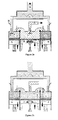
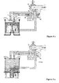
- Figures 1 to 2 show a first mode of an internal combustion engine five stroke by controlled ignition of the invention and which includes three cylinders arranged in line. More specifically, this engine has two cylinders high pressure oxidizers 2, 3 located at the ends the crankshaft (not shown) of the engine and operating on the cycle of a four engine time and a central cylinder 1 low pressure which operates in a two-stroke mode. The volume of low pressure cylinder 1 is greater than that of oxidizing cylinders 2, 3.
- a heat exchanger 15 is connected by tubing 18 to the outlet of discharge from a compressor device (no shown), which discharges precompressed air, and the exchanger outlet is connected to the two cylinders high pressure oxidizers 2, 3 by pipes 13, 14 air-fuel mixture intake precompressed.
- Tubes 13, 14 are provided with intake valves 8, 10 associated with the cylinders oxidizers 2, 3.
- the introduction of fuel takes place at the intake manifolds 13, 14 by means of a controlled injection device 35.
- the working chambers C2, C3 of the oxidizing cylinders 2, 3 are connected to the working chamber C1 of the low pressure cylinder respectively by transfer pipes 16, 17 of the combined gases or burned.
- the transfer pipes 16, 17 are provided respectively with transfer valves 9, 11 associated with the oxidizing cylinders 2, 3.
- the transfer valves 9 and 11, the valves air intake or air-fuel mixture 8, 10 as well as the spark plugs (not shown) are in the cylinder heads 2a, 3a of the cylinders high pressure oxidizers 2, 3.
- the working chamber C1 of the lower cylinder pressure 1 is closed by a cylinder head la which comprises a valve 7 for closing a tube exhaust 19 connected to the cylinder head and communicating with the working chamber C1.
- the low pressure cylinder 1 forms with the high pressure oxidizer cylinder left 2, one first pair of relaxing cylinders, while it form with the right high pressure oxidizing cylinder 3, a second pair of expansion cylinders, such as this will become apparent from the following description of the engine operation, referring to the figures 2a to 2d.
- the pistons 5 and 6 of the high pressure oxidizing cylinders 2, 3 are going down in cylinders 2, 3 for the low pressure piston 4 goes up in the cylinder 1.
- the left combustion cylinder 2 is in the process admit a pre-compressed air-fuel mixture to through the intake valve 8, which is open to this effect.
- Low pressure cylinder 1 is in process to discharge the combustion gases through the valve exhaust 7, which is open, to the manifold exhaust 19.
- the right combustion cylinder 3 is relaxing the gas for the first time combusted.
- the pistons 5, 6 of the high pressure oxidizing cylinders 2, 3 are in going down again in cylinders 2, 3 while the low pressure piston 4 goes up to new in cylinder 1.
- Oxidizing cylinder 3 is admitting a combustible air mixture pre-compressed through the inlet valve 10, which is open for this purpose.
- the low pressure cylinder 1 is pushing the combusted gases through the exhaust valve 7, which is open, towards the exhaust manifold 19.
- the combustion cylinder left 2 is relaxing for the first time the combined gases.
- the pistons 5, 6 of the cylinders high pressure oxidizers 2, 3 are go back up in these cylinders while the piston low pressure 4 descends into cylinder 1.
- the right oxidizing cylinder 3 is compressing the air-fuel mixture he just admitted and towards the end of this compression, this air-fuel mixture is ignited by the ignition spark of the spark plug, all the valves 10, 11 associated with this cylinder being closed.
- the low pressure cylinder 1 is in the process of admitting the combined gases into coming from the left oxidizing cylinder 2, which expels these same gases through the tubing of transfer 16, the transfer valve associated 9 being open. Because the volume of the low pressure cylinder 1 is larger than the volume of the combustion cylinder 2, the transfer of combustion gases from the combustion cylinder 2 to the cylinder low pressure 1 is accompanied by a relaxation of these combined gases, producing usable work on the Crankshaft.
- the motor with three-cylinder five-stroke internal combustion differs from the one described above by the way to introduce the fuel which is directly injected towards the end of the compression into the combustion of high pressure oxidizing cylinders 2, 3 where it will ignite spontaneously.
- the power of the heat exchanger 15 as well as the reports displacement and compression should be well heard readjusted.
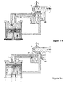
- the second trigger Combustion gases in the cylinder central oxidant 3 is carried out by transferring them simultaneously to the two low pressure cylinders adjacent 1 through open valves 11 and pipes 17 as shown in FIG. 3b.
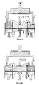
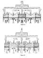
- the Figures 3a to 3d show in detail the four phases encountered during two rounds of the five internal combustion engine crankshaft five-cylinder time, where the hatched areas in horizontal lines are filled with air only and the hatched areas in small circles are filled with combined gases. There is no point in describing these four phases which stand out clearly from those of the motor five-stroke three-cylinder described in detail previously with reference to Figures 2a to 2d.
- FIG 4 Another embodiment of the five-stroke, three-cylinder internal combustion is illustrated in Figure 4, where the tubing transfer 16, 17 can be closed off only on the side of the oxidizing cylinders 2, 3 per valves 9 and 11, but also on the side of the low pressure cylinder 1 by means of valves auxiliary transfer 23 and 24, respectively.
- Transfer valves 9, 23 fitted respectively in cylinder heads 2a and 1a and in ends of the transfer tubing 16 connecting the working chamber C2 of the left combustion cylinder 2 to the working chamber C1 of the lower cylinder pressure 1, open and close approximately synchronously.
- valves of transfer 11, 24 mounted respectively in the cylinder heads 3a and 1a and at the ends of the manifold transfer 17 connecting the working chamber C3 of the right oxidizing cylinder 3 to working chamber C1 low pressure cylinder 1, open and close approximately synchronously.
- interest to use the auxiliary transfer valves 23, 24 is on the one hand to reduce the dead space of the low pressure cylinder 1 by separating the volume of the non-active transfer tubing 16, 17 during the second expansion of the combined gases by the volume of the working chamber C1 of the low pressure cylinder 1.
- this transfer valve 23, 24 prevents the valve from main transfer closed 9, 11 does not undergo its downstream the relatively high pressure prevailing in the low pressure cylinder 1 at the start of the second trigger, pressure that could have tendency to open the transfer valve main 9, 11, associated with the oxidizing cylinder 2, 3.
- Turbocharging basically consists of a turbine, which is driven by the expansion of the combined gases in origin of the internal combustion engine and which, at in turn, drives a compressor that compresses the air admitted in the engine cylinders.
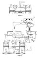
- FIG. 5 illustrates an embodiment of turbocharging a little more sophisticated.
- the combined and expanded gases a second time in the low pressure cylinder 1 are routed through three different routes or tubing 19, 25, 31 to the exhaust manifold 29 located at the entrance to a turbine 32.
- the three exhaust pipes 19, 25, 31 can be plugged on the low pressure cylinder side by exhaust valves 7 and 22 respectively located in cylinder head 1a to which are connected the two pipes 19, 25 of the low pressure cylinder 1 and by exhaust lights 21 arranged in low pressure cylinder liner 1. Lights exhaust 21 will only be discovered by the piston low pressure 4 only when it is close to its bottom dead center.
- Tubing 31 opens directly into the inlet exhaust manifold 29.
- the two exhaust valves 7, 22 are controlled so as not to open and close from synchronously.
- Combined gas flows in the exhaust pipes 19, 25 connected to the low pressure cylinder head 1 are either directed to the connected exhaust manifold 29 at the inlet of turbine 32, i.e. towards the manifold exhaust 30 connected to the turbine outlet where the pressure level approaches that of the ambient pressure.
- valves of diversion 27, 28 of the exhaust gases are arranged in the exhaust pipes 19, 25 opposite to their ends connected to cylinder head 1a low pressure 1 and can occupy a position closed transverse to the pipes 19, 25 for the shut off and direct the combined gases to the inlet of the turbine 32 through open holes 19a, 25a by the valves 27, 28 and produced through walls of the pipes 19, 25 in communication with the collector 29 which communicates with the entrance to the turbine 32, or an open position of the pipes 19, 25 and closing the holes 19a, 25a, for direct the combined gases directly into the outlet exhaust manifold 30 in which open the pipes 19, 25.
- a valve of the type waste-gate 26 is arranged between the collector inlet exhaust 29 and the manifold exhaust outlet 30 from turbine 32 for support the pressure setting at the inlet of the turbine depending on the load.
- This exhaust system to the turbine input is to reduce to the extent possible the discharge pressure inside of the low pressure cylinder 1 during the stroke advancement of the piston 4 thereof.
- Figure 5 also shows a valve deviation 36 on the intake side, normally closed, which, in the open position, allows the flow free air from the air intake manifold pre-compressed 18 to intake manifold auxiliary 34, which opens to the ambient air.
- the advantage of the auxiliary intake manifold 34 and of the associated deflection valve 36 is on one side to admit air bypassing compressor 12 at very low engine load and on the other side act as a safety valve and tubing, in the when the adjustment of the discharge pressure of the compressor 12 can no longer be carried out, further by example, to technical failures, by means of the valve 26, positioned at the inlet of the turbine 32 in order to regulate the power thereof.
- This auxiliary intake manifold 34 is, in plus, fitted with a throttle valve 33 for further reduce the intake pressure in the very low loads and operation at engine idling.
- FIGS 6a to 6c show the mode combustion gas evacuation in case the charge will be so low that overeating will not be necessary.
- the valve 26 is completely open and is controlled so that maintain a minimum pressure at the inlet of the turbine 32 to ensure a recovery regime suitable.
- the two deflection valves 27, 28 are in the open position to direct the gases exhaust from the pipes exhaust 19, 25 directly, without going to through the turbine 32, towards the manifold exhaust 30 at the outlet of the turbine.
- the low pressure piston 4 after having completed the second expansion of the combined gases, comes to its bottom dead center position and exhaust lights 21, which are arranged in the low pressure cylinder 1, are discovered and, thanks at a residual pressure in the low cylinder pressure 1 higher than the pressure prevailing in the exhaust manifold 29 at the inlet of the turbine 32, part of the combined gases contained in the low pressure cylinder 1 will flow through the exhaust lights 21 and along the exhaust manifold 31 to the manifold exhaust 29 where the pressure will barely be above ambient pressure after opening valve 26. Therefore, the pressure at the interior of the low pressure cylinder 1 will drop to roughly reach the pressure level room. At this position of the low pressure piston 4, the two exhaust valves 7 and 22 are still closed.
- the low pressure piston 4 is located in such a position that the lights exhaust 21 will again be closed by it, a first exhaust valve 7 opens, and the piston 4 of the low pressure cylinder 1 while advancing or ascending further into the cylinder will drive out a other part of the gases combusted through the valve open exhaust 7 and along the tubing exhaust 19 associated directly, without passing via turbine 32, towards the exhaust manifold 30 located at the outlet of the turbine, the check valve deflection 27 being in the open position.
- the low pressure piston 4 is advanced further into the cylinder and the first exhaust valve 7 has closed.
- the second exhaust valve 22 is now open and the piston 4 of the low pressure cylinder 1 while advancing more will expel one last part of the gas combusted through the open exhaust valve 22 along the associated exhaust pipe 25 directly, without passing through the turbine 32, towards the exhaust manifold 30 located at the outlet of the turbine 32, the deflection valve 28 being located open position.
- FIGS 7a to 7c show the mode combustion gas evacuation in case the charge will always be low, but where a slight engine supercharging will however already be necessary.
- Valve 26 is no longer completely open and is controlled to maintain a pressure at the inlet of turbine 32 as a function of the low load requested.
- the two valves of deflection 27, 28 are in the open position for directing exhaust gases from exhaust pipes 19, 25 directly, without pass through the turbine 32, towards the collector exhaust 30 at the outlet of the turbine. Only the quantity of gas evacuated by lights exhaust 21 located at the bottom of the lower cylinder pressure 1 is directed to the turbine 32 to be there relaxed.
- Combustion gases discharged through the valves exhaust 7, 22 located in the cylinder head la low pressure cylinder 1 do not cross the turbine 32 and the pressure in the cylinder low pressure will drop to a level close to that of ambient pressure, as soon as one of the two valves exhaust 7, 22 will open.
- FIGS 8a to 8c show the mode combustion gas evacuation in case the load will be medium and where overcharging more engine thrust becomes necessary.
- Valve 26 is controlled to maintain pressure at the inlet of the turbine 32 as a function of the load requested.
- the deflection valve 27 associated with the exhaust manifold 19 associated with the valve exhaust 7, which will open as soon as the piston low pressure 4 just shut off the lights exhaust 21, is in the closed position so that direct the exhaust gases flowing along the corresponding exhaust pipe 19 to the inlet of the turbine 32 to be expanded there.
- the other deflection valve 28 associated with the tubing exhaust 25 associated with the exhaust valve 22, which will open later when the other valve exhaust 7 will close, is in the open position so as to direct the exhaust gases origin of the exhaust manifold corresponding 25 directly, without going through the turbine 32, to the exhaust manifold 30 to the outlet of turbine 32.
- the quantity gas discharged through the exhaust lights 21 located at the bottom of the low pressure cylinder 1 and the quantity of gas evacuated by the exhaust valve 7 opening first will be directed to the turbine 32 to be expanded there.
- Combined gases discharged through the other exhaust valve 22 opening the last will not cross the turbine 32 and the pressure in the low pressure cylinder 1 will drop to a level close to that of pressure ambient, as soon as the exhaust valve 22 open to.
- FIGS 9a to 9c show the mode combustion gas evacuation in case the load will be high and where a maximum boost of the engine becomes necessary.
- Valve 26 will controlled to maintain pressure at the inlet of the turbine 32 as a function of the load requested.
- the two deflection valves 27, 28 associated with the exhaust pipes 19, 25 which are associated with the exhaust valves 7, 22, are in closed position to direct gas exhaust flowing along the pipes corresponding exhaust 19, 25 to the inlet of the turbine 32 to be expanded there. This time all the gases discharged from the low pressure cylinder 1, to except those who will pass through the valve 26 possibly open, are directed to the turbine 32 to be expanded. It is only in this situation that the pressure in the cylinder low pressure 1 will be close to back pressure created by the turbine throughout the race exhaust.
- This embodiment of the gas evacuation to the turbine of the turbo-compressor group could obviously be made less complex by removing the exhaust lights 21 and advancing the opening of the first valve exhaust 7.
- the deflection valve 27 which is associated with the corresponding exhaust pipe 19 will be closed all the time and may therefore be deleted.
- the five-stroke internal combustion engine subject of the present invention may be used in any technical field where we use currently such engines, especially in the truck transport.
- the main advantage of the invention by compared to existing engines is a net increased energy efficiency.
- the calculations show an increase in this yield about 20% at full load to 25% at load partial, in the case of a positive-ignition engine (petrol) and from 14 to 25% in the case of a spontaneous ignition (diesel).
- the other advantage of the invention over existing engines is a power density improved, thanks to the possibility of increased supercharging of up to absolute pressure at cylinder intake oxidizers from 3 to 5 bars.
Landscapes
- Engineering & Computer Science (AREA)
- Chemical & Material Sciences (AREA)
- Combustion & Propulsion (AREA)
- Mechanical Engineering (AREA)
- General Engineering & Computer Science (AREA)
- Output Control And Ontrol Of Special Type Engine (AREA)
- Supercharger (AREA)
- Catalysts (AREA)
Abstract
Description
Pendant le troisième temps, en redescendant ou reculant dans le cylindre, le piston permet aux gaz comburés ou brûlés de se détendre et c'est à ce moment que le travail utilisable est produit. Quand le piston approche de son point mort bas, les gaz se trouvant encore sous une certaine pression s'échappent à travers une soupape d'échappement aménagée dans la culasse du cylindre. Pendant le quatrième temps, le piston remonte à nouveau et cette évacuation des gaz comburés est ainsi complétée.
- la figure 1 est une vue en coupe verticale du bloc moteur d'un premier mode de réalisation d'un moteur à combustion interne à trois cylindres conforme à l'invention ;
- les figures 2a à 2d sont des vues en coupe identiques à celles de la figure 1 et représentant quatre phases de fonctionnement du moteur se déroulant pendant deux tours de rotation du vilebrequin de celui-ci ;
- les figures 3a à 3d représentent en coupe verticale du bloc moteur d'un second mode de réalisation du moteur à cinq cylindres et relatives au fonctionnement de celui-ci pendant deux tours de rotation du vilebrequin du moteur;
- la figure 4 est une vue en coupe verticale de la culasse d'un cylindre basse pression où deux soupapes supplémentaires de transvasement sont prévues pour obturer les canaux de transvasement du côté de ce cylindre ;
- la figure 5 représente le moteur à trois cylindres de la figure 1 suralimenté par un groupe turbocompresseur, dont la turbine est alimentée par les gaz d'échappement acheminés par trois voies différentes ;
- les figures 6a à 6c représentent le moteur de la figure 5 fonctionnant à très faible charge sans être suralimenté et dont le piston du cylindre basse pression occupe trois positions au cours de la course d'échappement ;
- les figures 7a à 7c représentent le moteur de la figure 5 fonctionnant à faible charge en étant faiblement suralimenté et dont le piston du cylindre basse pression occupe trois positions au cours de la course d'échappement ;
- les figures 8a à 8c représentent le moteur de la figure 5 fonctionnant à charge partielle en étant que partiellement suralimenté et dont le piston du cylindre basse pression occupe trois positions au cours de la course d'échappement ; et
- les figures 9a à 9c représentent le moteur de la figure 5 fonctionnant à pleine charge en étant pleinement suralimenté et montrant les trois positions du piston du cylindre basse pression du moteur au cours de la course d'échappement.
Claims (8)
- Procédé de réalisation d'un moteur à combustion interne du type comprenant au moins un cylindre (2 ; 3) qui comprend une chambre de travail (C2 ; C3) de volume variable par le déplacement dans le cylindre (2 ; 3) d'un piston (5 ; 6) entre une position de point mort haut et une position de point mort bas, sous l'effet de forces de pression engendrées périodiquement dans ladite chambre, à chaque cylindre (2 ; 3) étant associés des moyens d'admission et d'évacuation d'un fluide gazeux, le piston de chaque cylindre étant relié à un arbre vilebrequin du moteur, utilisant au moins, d'une part, un cylindre (1) fonctionnant en cylindre basse pression suivant un mode du type deux temps, qui comprennent l'admission accompagnée de la détente produisant un travail utile au cours de chaque course du piston du cylindre basse pression (1) vers son point mort bas et l'échappement d'un fluide gazeux au cours de chaque course du piston vers son point mort haut et, d'autre part, deux cylindres (2, 3) fonctionnant en cylindres comburants suivant un mode du type quatre temps, qui comprennent l'admission de l'air ou d'un mélange air-combustible au cours de la première course du piston de chacun des cylindres comburants (2, 3) vers son point mort bas, la compression de cet air ou du mélange air-combustible dans le cylindre comburant au cours de la première course du piston vers son point mort haut, suivie de la combustion, la détente des gaz comburés au cours de la deuxième course du piston vers son point mort bas produisant un travail utile et le refoulement des gaz comburés au cours de la deuxième course du piston vers son point mort haut, la cylindrée de chacun des cylindres comburants (2, 3) étant inférieure à celle du cylindre basse pression (1), les cylindres comburants (2, 3) refoulant alternativement leurs gaz comburés vers le cylindre basse pression (1) en vue d'une deuxième détente des gaz comburés et de leur échappement du moteur, et comprenant un moyen de suralimentation des cylindres comburants (2, 3) caractérisé en ce que le rapport de compression volumétrique des cylindres comburants est relativement faible de manière à pouvoir être fortement suralimenté.
- Moteur à combustion interne pour la mise en oeuvre du procédé selon la revendication 1, caractérisé en ce qu'il comprend cinq cylindres rangés en ligne, comprenant trois cylindres comburants haute pression (2, 3) et deux cylindres basse pression (1), deux cylindres comburants (2) se trouvant aux extrémités de l'arbre vilebrequin auquel sont reliés les deux pistons (5) de ces cylindres, le troisième cylindre comburant haute pression (3) se trouvant au milieu et pouvant communiquer avec les deux cylindres basse pression adjacents (1) par respectivement au moins une soupape (11) et une tubulure de transvasement (17) de façon à transférer simultanément, lors de la deuxième détente, les gaz comburés contenus dans le cylindre comburant central (3) dans les deux cylindres basse pression (1) qui lui sont associés, et en ce que ces même cylindres basse pression (1) reçoivent au cours du tour de vilebrequin suivant lors du déplacement du piston vers son point mort bas l'entièreté des gaz comburés contenus dans le cylindre comburant (2) se trouvant à l'extrémité du vilebrequin et à côté du cylindre basse pression (1) en question.
- Moteur à combustion interne selon la revendication 2, caractérisé en ce qu'il comprend un nombre impair, supérieur à cinq, de cylindres rangés en ligne de façon qu'aux extrémités du vilebrequin de celui-ci se trouvent deux cylindres comburants haute pression (2) et de façon que les autres cylindres comburants haute pression (3) se trouvent entre deux cylindres basse pression (1) et puissent communiquer avec les deux cylindres basse pression adjacents (1) par respectivement au moins une soupape et une tubulure de transvasement de façon à transférer simultanément, lors de la deuxième détente, les gaz comburés contenus dans le cylindre comburant (3) vers les deux cylindres basse pression (1) qui lui sont associés.
- Moteur à combustion interne selon la revendication 2 ou 3, caractérisé en ce qu'il comprend un moyen de commande de la pression de suralimentation d'air ou du mélange air-combustible à l'admission des cylindres comburants (2,3) pour réaliser le réglage de charge du moteur, pour un régime donné, pour une grande partie de la plage du couple de fonctionnement de celui-ci, et un compresseur entraíné mécaniquement ou un groupe turbo-compresseur, dont la turbine est entraínée par une détente supplémentaire des gaz d'échappement du moteur, pour réaliser la précompression de l'air ou du mélange air-combustible, le cas échéant refroidi au moyen d'un échangeur de chaleur (15), l'entrée de la turbine (32) étant raccordée à un collecteur de gaz comburés (29) pourvu d'une soupape du type waste-gate (26) pouvant, en position ouverte ou partiellement ouverte, dévier tout ou partie des gaz comburés directement vers l'échappement du moteur.
- Moteur à combustion interne selon l'une des revendications 2 à 4, caractérisé en ce que les chambres de travail (C2, C3) des cylindres comburants (2, 3) comprennent des moyens d'injection directe du combustible dans l'air comprimé au cours de la course de compression pour des rapports masse d'air divisée par masse de combustible variables et commandés en fonction de la charge du moteur, les chambres de travail (C2, C3) des cylindres comburants haute pression (2, 3) étant équipées d'un moyen permettant d'enflammer le mélange air-combustible.
- Moteur à combustion interne selon l'une des revendications 2 à 5, caractérisé en ce qu'il comprend des lumières d'échappement (21) aménagées dans le cylindre basse pression (1) pour effectuer, entièrement ou partiellement, l'échappement des gaz comburés contenus dans le cylindre (1), les lumières d'échappement étant découvertes par le piston (4) du cylindre basse pression (1) quand celui-ci se trouve proche de son point mort bas.
- Moteur à combustion interne selon l'une des revendications 2 à 6, caractérisé en ce que, lorsque le groupe turbo-compresseur précité réalise la précompression de l'air ou du mélange air-combustible à l'admission des cylindres comburants (2, 3), jusqu'à trois tubulures différentes (19, 25, 31) alimentées d'une manière non simultanée refoulent, au cours de la course du piston (4) du cylindre basse pression (1) vers son point mort haut, en direction de l'entrée de la turbine (29), les gaz comburés contenus dans le cylindre basse pression (1), toutes les tubulures, à l'exception de la dernière, (19, 25) comportant chacune un clapet de déviation (27, 28) des gaz comburés commandé individuellement en fonction de la charge du moteur et qui, en position ouverte, guide les gaz comburés en provenance du cylindre basse pression (1) directement vers l'échappement tandis qu'en position fermée, le clapet de déviation (27, 28) guide ces mêmes gaz comburés vers le collecteur des gaz comburés (29) à l'entrée de la turbine (32), la dernière tubulure d'échappement (31) étant la première en communication avec la chambre de travail (C1) du cylindre basse pression (1).
- Moteur à combustion interne selon l'une des revendications 2 à 7, caractérisé en ce que les tubulures de transvasement (16, 17) comprennent chacune une soupape de transvasement auxiliaire supplémentaire (23, 24) associée à la culasse (la) du cylindre basse pression (1) et s'ouvrant approximativement de façon synchrone avec la soupape de transvasement principale (9,11) de la même tubulure de transvasement (16, 17) associée à la culasse (2a, 3a) du cylindre comburant (2,3).
Applications Claiming Priority (2)
| Application Number | Priority Date | Filing Date | Title |
|---|---|---|---|
| BE2000/0684A BE1013791A5 (fr) | 2000-10-26 | 2000-10-26 | Moteur a combustion interne a cinq temps. |
| BE200000684 | 2000-10-26 |
Publications (2)
| Publication Number | Publication Date |
|---|---|
| EP1201892A1 true EP1201892A1 (fr) | 2002-05-02 |
| EP1201892B1 EP1201892B1 (fr) | 2006-02-01 |
Family
ID=3896731
Family Applications (1)
| Application Number | Title | Priority Date | Filing Date |
|---|---|---|---|
| EP01125051A Expired - Lifetime EP1201892B1 (fr) | 2000-10-26 | 2001-10-22 | Moteur à combustion interne à cinq temps |
Country Status (5)
| Country | Link |
|---|---|
| US (1) | US6553977B2 (fr) |
| EP (1) | EP1201892B1 (fr) |
| AT (1) | ATE317058T1 (fr) |
| BE (1) | BE1013791A5 (fr) |
| DE (1) | DE60116942T2 (fr) |
Cited By (3)
| Publication number | Priority date | Publication date | Assignee | Title |
|---|---|---|---|---|
| EP1995430A2 (fr) | 2007-05-24 | 2008-11-26 | Gerhard Schmitz | Procédé pour améliorer un moteur à combustion interne |
| CN106246339A (zh) * | 2015-06-10 | 2016-12-21 | 通用汽车环球科技运作有限责任公司 | 具有受控膨胀的排气复合式内燃机 |
| FR3161000A1 (fr) * | 2024-04-05 | 2025-10-10 | Ehm | Procédé de contrôle d’un moteur à cinq temps d’un véhicule. |
Families Citing this family (50)
| Publication number | Priority date | Publication date | Assignee | Title |
|---|---|---|---|---|
| US6880501B2 (en) * | 2001-07-30 | 2005-04-19 | Massachusetts Institute Of Technology | Internal combustion engine |
| WO2003012266A1 (fr) | 2001-07-30 | 2003-02-13 | Massachusetts Institute Of Technology | Moteur a combustion interne |
| DE10204482A1 (de) * | 2002-02-05 | 2003-08-14 | Daimler Chrysler Ag | Brennkraftmaschine |
| CZ297785B6 (cs) * | 2003-04-01 | 2007-03-28 | Zpusob a zarízení pro premenu tepelné energie na mechanickou | |
| US6776144B1 (en) * | 2003-05-28 | 2004-08-17 | Lennox G. Newman | Five stroke internal combustion engine |
| EP1609967A1 (fr) * | 2004-06-22 | 2005-12-28 | Mica Stanojevic | Moteur à combustion interne à 5 temps |
| US7273023B2 (en) * | 2005-03-11 | 2007-09-25 | Tour Engine, Inc. | Steam enhanced double piston cycle engine |
| CN101548082B (zh) * | 2005-03-11 | 2013-01-23 | 托尔发动机股份有限公司 | 双活塞循环发动机 |
| US7614369B2 (en) * | 2005-05-13 | 2009-11-10 | Motorpat, L.L.C. | Reciprocating cylinder engine |
| US7201156B1 (en) * | 2005-05-24 | 2007-04-10 | Wait Irving S | Thermal transfer internal combustion engine |
| US7143725B1 (en) * | 2005-11-22 | 2006-12-05 | Lung Tan Hu | Dual six-stroke self-cooling internal combustion engine |
| CN100360773C (zh) * | 2006-04-06 | 2008-01-09 | 郑哲立 | 超高增压双循环变排量内燃机 |
| US20080017141A1 (en) * | 2006-07-20 | 2008-01-24 | Gile Jun Yang Park | Air/fuel double pre-mix self-supercharging internal combustion engine with optional freewheeling mechanism |
| US8091521B2 (en) * | 2006-07-20 | 2012-01-10 | Gile Jun Yang Park | Self-supercharging engine with freewheeling mechanism |
| US8434454B2 (en) | 2006-07-20 | 2013-05-07 | Gile Jun Yang Park | Dual crankshaft engines |
| US7937943B2 (en) * | 2006-12-22 | 2011-05-10 | Yiding Cao | Heat engines |
| US7634988B1 (en) * | 2007-04-26 | 2009-12-22 | Salminen Reijo K | Internal combustion engine |
| KR101196447B1 (ko) | 2007-06-05 | 2012-11-01 | 자여 준 양 박 | 프리휠링 기구를 구비한 공기/연료 이중 예비 혼합 자체 과급 내연 기관 |
| US20090049822A1 (en) * | 2007-08-23 | 2009-02-26 | James Michael Fichera | Method, apparatus and system for thermal regeneration |
| BE1018159A5 (fr) * | 2008-05-23 | 2010-06-01 | Gerhard Schmitz | Moteur a combustion interne suralimente par turbo-compresseur. |
| WO2010036994A1 (fr) * | 2008-09-26 | 2010-04-01 | Voisin Robert D | Entraînement d’un moteur à combustion interne |
| US8371256B2 (en) * | 2009-05-27 | 2013-02-12 | GM Global Technology Operations LLC | Internal combustion engine utilizing dual compression and dual expansion processes |
| WO2010145628A1 (fr) | 2009-06-15 | 2010-12-23 | Obrist Engineering Gmbh | Véhicule à moteur pourvu d'un moteur à combustion interne et d'un moteur électrique |
| US8646421B2 (en) * | 2009-10-23 | 2014-02-11 | GM Global Technology Operations LLC | Engine with internal exhaust gas recirculation and method thereof |
| US8794218B2 (en) | 2009-11-25 | 2014-08-05 | Robert L. Murtha | Reclaim internal combustion engine |
| DE102010015698A1 (de) * | 2010-04-16 | 2011-10-20 | Seneca International Ag | Brennkraftmotor |
| DE102010025051A1 (de) * | 2010-06-18 | 2011-12-22 | Seneca International Ag | Brennkraftmotor |
| DE102010025050A1 (de) * | 2010-06-18 | 2011-12-22 | Seneca International Ag | Brennkraftmotor |
| WO2013038228A1 (fr) * | 2011-09-18 | 2013-03-21 | Gabora Akram Mohammed Abbashar | Moteur à combustion interne à six temps |
| US9080508B2 (en) * | 2012-11-02 | 2015-07-14 | GM Global Technology Operations LLC | Piston compound internal combustion engine with expander deactivation |
| US8978602B2 (en) * | 2012-12-12 | 2015-03-17 | Caterpillar Inc. | Six-stroke engine power density matching system and method |
| US8910613B2 (en) * | 2013-03-14 | 2014-12-16 | Kurt Amplatz | Internal combustion engine |
| DE102013006703B4 (de) | 2013-04-18 | 2017-02-09 | Reinhard Legat | Verbrennungsmotor mit Nachexpansion des Arbeitsgases im Teillastbereich |
| US8904987B2 (en) * | 2013-04-26 | 2014-12-09 | Gary G. Gebeau | Supercharged engine design |
| DE102013009292A1 (de) | 2013-06-07 | 2014-12-11 | Poul Henrik Woelfle | Mehrzylinder-Verbrennungsmotor mit optionaler Vergrößerung des Expansionsvolumens und Nachexpansion und entsprechende Verfahren |
| DE102013009291A1 (de) | 2013-06-07 | 2014-12-11 | Poul Henrik Woelfle | Mehrzylinder-Verbrennungsmotor mit optionaler Nachexpansion und entsprechende Verfahren |
| EP3123006B1 (fr) * | 2014-03-28 | 2018-03-07 | Volvo Truck Corporation | Moteur à combustion interne |
| US9518506B2 (en) | 2014-11-10 | 2016-12-13 | Ford Global Technologies, Llc | Systems and methods for control of turbine-generator via valve deactivation in a split exhaust engine system |
| US9624850B2 (en) | 2014-11-10 | 2017-04-18 | Ford Global Technologies, Llc | Systems and methods for control of turbine-generator via exhaust valve timing and duration modulation in a split exhaust engine system |
| US9574491B2 (en) * | 2015-01-30 | 2017-02-21 | GM Global Technology Operations LLC | Single shaft dual expansion internal combustion engine |
| US9605708B2 (en) * | 2015-01-30 | 2017-03-28 | GM Global Technology Operations LLC | Single-shaft dual expansion internal combustion engine |
| US9677464B2 (en) * | 2015-06-12 | 2017-06-13 | GM Global Technology Operations LLC | Single-shaft dual expansion internal combustion engine |
| US9810122B2 (en) | 2015-06-22 | 2017-11-07 | Ford Global Technologies, Llc | Engine exhaust temperature control |
| US9862262B2 (en) | 2015-07-30 | 2018-01-09 | Ford Global Technologies, Llc | Hybrid vehicle powertrain |
| CN105673202A (zh) * | 2016-02-14 | 2016-06-15 | 上海交通大学 | 五冲程发动机 |
| SE541204C2 (en) * | 2017-10-18 | 2019-04-30 | Olshammar Nebula Ab | Internal combustion engine with a combustion cylinder, an exhaust cylinder, and a turbocharge arrangement |
| US10519835B2 (en) * | 2017-12-08 | 2019-12-31 | Gm Global Technology Operations Llc. | Method and apparatus for controlling a single-shaft dual expansion internal combustion engine |
| US10865717B2 (en) * | 2018-06-05 | 2020-12-15 | Alexey TYSHKO | Dual mode internal combustion engine |
| JP7401328B2 (ja) * | 2020-01-31 | 2023-12-19 | ダイハツ工業株式会社 | 内燃機関 |
| CN116163835B (zh) * | 2023-02-22 | 2024-06-18 | 北京理工大学 | 一种可变燃料、可变冲程高效直线内燃发电机及工作方法 |
Citations (7)
| Publication number | Priority date | Publication date | Assignee | Title |
|---|---|---|---|---|
| FR612099A (fr) * | 1925-06-19 | 1926-10-16 | Moteur à explosion à cinq phases par tour de l'arbre moteur | |
| FR1058109A (fr) * | 1952-06-07 | 1954-03-15 | Perfectionnement aux moteurs à explosion | |
| FR1091774A (fr) * | 1952-10-18 | 1955-04-14 | Cycle de travail à cinq temps pour moteurs endothermiques | |
| US3312206A (en) * | 1964-12-09 | 1967-04-04 | Radovic Dusan | Reciprocating engines |
| FR2474584A1 (fr) * | 1979-09-24 | 1981-07-31 | Etienne Charles | Procede permettant l'augmentation de la detente des gaz des moteurs thermiques |
| JPS6318131A (ja) * | 1986-07-11 | 1988-01-26 | Nippon Radiator Co Ltd | 5サイクルデイ−ゼルエンジン |
| EP0302042A1 (fr) * | 1987-07-30 | 1989-02-01 | Gerhard Schmitz | Moteur à combustion interne à six temps |
Family Cites Families (4)
| Publication number | Priority date | Publication date | Assignee | Title |
|---|---|---|---|---|
| BE1002364A4 (fr) * | 1988-12-30 | 1991-01-15 | Schmitz Gerhard | Moteur a combustion interne a deux temps etages. |
| US5265564A (en) * | 1989-06-16 | 1993-11-30 | Dullaway Glen A | Reciprocating piston engine with pumping and power cylinders |
| US5551236A (en) * | 1994-05-02 | 1996-09-03 | Dresser Industries, Inc. | Turbocharger control management system |
| US6318310B1 (en) * | 1999-08-05 | 2001-11-20 | Caterpillar Inc. | Internal combustion engine |
-
2000
- 2000-10-26 BE BE2000/0684A patent/BE1013791A5/fr not_active IP Right Cessation
-
2001
- 2001-10-22 EP EP01125051A patent/EP1201892B1/fr not_active Expired - Lifetime
- 2001-10-22 AT AT01125051T patent/ATE317058T1/de active
- 2001-10-22 DE DE60116942T patent/DE60116942T2/de not_active Expired - Lifetime
- 2001-10-26 US US10/001,382 patent/US6553977B2/en not_active Expired - Lifetime
Patent Citations (7)
| Publication number | Priority date | Publication date | Assignee | Title |
|---|---|---|---|---|
| FR612099A (fr) * | 1925-06-19 | 1926-10-16 | Moteur à explosion à cinq phases par tour de l'arbre moteur | |
| FR1058109A (fr) * | 1952-06-07 | 1954-03-15 | Perfectionnement aux moteurs à explosion | |
| FR1091774A (fr) * | 1952-10-18 | 1955-04-14 | Cycle de travail à cinq temps pour moteurs endothermiques | |
| US3312206A (en) * | 1964-12-09 | 1967-04-04 | Radovic Dusan | Reciprocating engines |
| FR2474584A1 (fr) * | 1979-09-24 | 1981-07-31 | Etienne Charles | Procede permettant l'augmentation de la detente des gaz des moteurs thermiques |
| JPS6318131A (ja) * | 1986-07-11 | 1988-01-26 | Nippon Radiator Co Ltd | 5サイクルデイ−ゼルエンジン |
| EP0302042A1 (fr) * | 1987-07-30 | 1989-02-01 | Gerhard Schmitz | Moteur à combustion interne à six temps |
Non-Patent Citations (1)
| Title |
|---|
| PATENT ABSTRACTS OF JAPAN vol. 012, no. 222 (M - 712) 24 June 1988 (1988-06-24) * |
Cited By (4)
| Publication number | Priority date | Publication date | Assignee | Title |
|---|---|---|---|---|
| EP1995430A2 (fr) | 2007-05-24 | 2008-11-26 | Gerhard Schmitz | Procédé pour améliorer un moteur à combustion interne |
| EP2107226A1 (fr) | 2007-05-24 | 2009-10-07 | Gerhard Schmitz | Moteur à combustion interne d'encombrement minimal |
| CN106246339A (zh) * | 2015-06-10 | 2016-12-21 | 通用汽车环球科技运作有限责任公司 | 具有受控膨胀的排气复合式内燃机 |
| FR3161000A1 (fr) * | 2024-04-05 | 2025-10-10 | Ehm | Procédé de contrôle d’un moteur à cinq temps d’un véhicule. |
Also Published As
| Publication number | Publication date |
|---|---|
| US6553977B2 (en) | 2003-04-29 |
| DE60116942D1 (de) | 2006-04-13 |
| EP1201892B1 (fr) | 2006-02-01 |
| US20020050253A1 (en) | 2002-05-02 |
| ATE317058T1 (de) | 2006-02-15 |
| DE60116942T2 (de) | 2006-10-26 |
| BE1013791A5 (fr) | 2002-08-06 |
Similar Documents
| Publication | Publication Date | Title |
|---|---|---|
| BE1013791A5 (fr) | Moteur a combustion interne a cinq temps. | |
| EP0376909B1 (fr) | Moteur à combustion interne | |
| EP0302042B1 (fr) | Moteur à combustion interne à six temps | |
| EP1084334B1 (fr) | Procede de fonctionnement et dispositif de moteur a injection d'air comprime additionnel fonctionnat en mono-energie, ou en bi-energie bi ou tri modes d'alimentation | |
| ES2392624T3 (es) | Motor híbrido de aire de ciclo dividido | |
| US6199369B1 (en) | Separate process engine | |
| FR2748776A1 (fr) | Procede de moteur a combustion interne cyclique a chambre de combustion independante a volume constant | |
| EP1018597B1 (fr) | Moteur compressé à combustion interne à deux ou à quatre temps | |
| BE1017617A5 (fr) | Moteur a combustion interne a quatre temps et demi. | |
| FR2485087A1 (fr) | Moteur a combustion interne | |
| FR2544384A1 (fr) | Turbomoteur compound perfectionne | |
| CA2319268A1 (fr) | Procede et dispositif de rechauffage thermique additionnel pour vehicule equipe de moteur depollue a injection d'air comprime additionnel | |
| EP0104541A2 (fr) | Procédé de transformation d'énergie thermique en énergie mécanique à l'aide d'un moteur à combustion ainsi que ce nouveau moteur | |
| FR2583108A2 (fr) | Procede d'amelioration du fonctionnement d'un moteur a combustion interne, a cycle court, et moteur a combustion interne a fonctionnement ameliore a cycle court et a structure simplifiee | |
| FR2538031A2 (fr) | Moteur deux temps a pistons complementaires et chambres independantes en zone de point mort haut | |
| EP1290326B1 (fr) | Moteur a combustion interne sans refroidissement exterieur | |
| FR2957631A1 (fr) | Element de moteur a combustion interne a detente prolongee et moteur a combustion interne comprenant un ou plusieurs de ces elements | |
| FR3147590A1 (fr) | Architecture d’un moteur thermique à dihydrogène et procédé de caractérisation des paramètres géométriques et fonctionnels dudit moteur | |
| WO1986000374A1 (fr) | Procede d'amelioration du fonctionnement d'un moteur a combustion interne a deux temps | |
| FR2778430A1 (fr) | Moteur a combustion interne rotatif sans pistons | |
| FR2531139A1 (fr) | Dispositif de controle d'un circuit de gaz d'une chambre de combustion | |
| CH539776A (fr) | Moteur thermique | |
| FR2708668A1 (fr) | Dispositif d'alimentation d'un moteur à explosion. | |
| FR3028563A1 (fr) | Piston alternatif et contenant faisant moteur thermique, pneumatique, hybride et recuperateur d'energie pneumatique | |
| FR2668543A1 (fr) | Moteur a gaz chaud. |
Legal Events
| Date | Code | Title | Description |
|---|---|---|---|
| PUAI | Public reference made under article 153(3) epc to a published international application that has entered the european phase |
Free format text: ORIGINAL CODE: 0009012 |
|
| AK | Designated contracting states |
Kind code of ref document: A1 Designated state(s): AT BE CH CY DE DK ES FI FR GB GR IE IT LI LU MC NL PT SE TR |
|
| AX | Request for extension of the european patent |
Free format text: AL;LT;LV;MK;RO;SI |
|
| 17P | Request for examination filed |
Effective date: 20020930 |
|
| AKX | Designation fees paid |
Free format text: AT BE CH CY DE DK ES FI FR GB GR IE IT LI LU MC NL PT SE TR |
|
| 17Q | First examination report despatched |
Effective date: 20050207 |
|
| GRAP | Despatch of communication of intention to grant a patent |
Free format text: ORIGINAL CODE: EPIDOSNIGR1 |
|
| GRAS | Grant fee paid |
Free format text: ORIGINAL CODE: EPIDOSNIGR3 |
|
| GRAA | (expected) grant |
Free format text: ORIGINAL CODE: 0009210 |
|
| AK | Designated contracting states |
Kind code of ref document: B1 Designated state(s): AT BE CH CY DE DK ES FI FR GB GR IE IT LI LU MC NL PT SE TR |
|
| PG25 | Lapsed in a contracting state [announced via postgrant information from national office to epo] |
Ref country code: IT Free format text: LAPSE BECAUSE OF FAILURE TO SUBMIT A TRANSLATION OF THE DESCRIPTION OR TO PAY THE FEE WITHIN THE PRESCRIBED TIME-LIMIT;WARNING: LAPSES OF ITALIAN PATENTS WITH EFFECTIVE DATE BEFORE 2007 MAY HAVE OCCURRED AT ANY TIME BEFORE 2007. THE CORRECT EFFECTIVE DATE MAY BE DIFFERENT FROM THE ONE RECORDED. Effective date: 20060201 Ref country code: NL Free format text: LAPSE BECAUSE OF FAILURE TO SUBMIT A TRANSLATION OF THE DESCRIPTION OR TO PAY THE FEE WITHIN THE PRESCRIBED TIME-LIMIT Effective date: 20060201 Ref country code: FI Free format text: LAPSE BECAUSE OF FAILURE TO SUBMIT A TRANSLATION OF THE DESCRIPTION OR TO PAY THE FEE WITHIN THE PRESCRIBED TIME-LIMIT Effective date: 20060201 |
|
| REG | Reference to a national code |
Ref country code: GB Ref legal event code: FG4D Free format text: NOT ENGLISH |
|
| REG | Reference to a national code |
Ref country code: CH Ref legal event code: EP |
|
| REG | Reference to a national code |
Ref country code: IE Ref legal event code: FG4D Free format text: LANGUAGE OF EP DOCUMENT: FRENCH |
|
| GBT | Gb: translation of ep patent filed (gb section 77(6)(a)/1977) |
Effective date: 20060317 |
|
| REF | Corresponds to: |
Ref document number: 60116942 Country of ref document: DE Date of ref document: 20060413 Kind code of ref document: P |
|
| PG25 | Lapsed in a contracting state [announced via postgrant information from national office to epo] |
Ref country code: DK Free format text: LAPSE BECAUSE OF FAILURE TO SUBMIT A TRANSLATION OF THE DESCRIPTION OR TO PAY THE FEE WITHIN THE PRESCRIBED TIME-LIMIT Effective date: 20060501 Ref country code: SE Free format text: LAPSE BECAUSE OF FAILURE TO SUBMIT A TRANSLATION OF THE DESCRIPTION OR TO PAY THE FEE WITHIN THE PRESCRIBED TIME-LIMIT Effective date: 20060501 |
|
| PG25 | Lapsed in a contracting state [announced via postgrant information from national office to epo] |
Ref country code: ES Free format text: LAPSE BECAUSE OF FAILURE TO SUBMIT A TRANSLATION OF THE DESCRIPTION OR TO PAY THE FEE WITHIN THE PRESCRIBED TIME-LIMIT Effective date: 20060512 |
|
| REG | Reference to a national code |
Ref country code: CH Ref legal event code: NV Representative=s name: TROESCH SCHEIDEGGER WERNER AG |
|
| NLV1 | Nl: lapsed or annulled due to failure to fulfill the requirements of art. 29p and 29m of the patents act | ||
| PG25 | Lapsed in a contracting state [announced via postgrant information from national office to epo] |
Ref country code: PT Free format text: LAPSE BECAUSE OF FAILURE TO SUBMIT A TRANSLATION OF THE DESCRIPTION OR TO PAY THE FEE WITHIN THE PRESCRIBED TIME-LIMIT Effective date: 20060703 |
|
| PG25 | Lapsed in a contracting state [announced via postgrant information from national office to epo] |
Ref country code: MC Free format text: LAPSE BECAUSE OF NON-PAYMENT OF DUE FEES Effective date: 20061031 |
|
| PLBE | No opposition filed within time limit |
Free format text: ORIGINAL CODE: 0009261 |
|
| STAA | Information on the status of an ep patent application or granted ep patent |
Free format text: STATUS: NO OPPOSITION FILED WITHIN TIME LIMIT |
|
| 26N | No opposition filed |
Effective date: 20061103 |
|
| PG25 | Lapsed in a contracting state [announced via postgrant information from national office to epo] |
Ref country code: GR Free format text: LAPSE BECAUSE OF FAILURE TO SUBMIT A TRANSLATION OF THE DESCRIPTION OR TO PAY THE FEE WITHIN THE PRESCRIBED TIME-LIMIT Effective date: 20060502 |
|
| PG25 | Lapsed in a contracting state [announced via postgrant information from national office to epo] |
Ref country code: TR Free format text: LAPSE BECAUSE OF FAILURE TO SUBMIT A TRANSLATION OF THE DESCRIPTION OR TO PAY THE FEE WITHIN THE PRESCRIBED TIME-LIMIT Effective date: 20060201 |
|
| PG25 | Lapsed in a contracting state [announced via postgrant information from national office to epo] |
Ref country code: CY Free format text: LAPSE BECAUSE OF FAILURE TO SUBMIT A TRANSLATION OF THE DESCRIPTION OR TO PAY THE FEE WITHIN THE PRESCRIBED TIME-LIMIT Effective date: 20060201 |
|
| REG | Reference to a national code |
Ref country code: FR Ref legal event code: PLFP Year of fee payment: 15 |
|
| PGFP | Annual fee paid to national office [announced via postgrant information from national office to epo] |
Ref country code: LU Payment date: 20151023 Year of fee payment: 15 |
|
| PGFP | Annual fee paid to national office [announced via postgrant information from national office to epo] |
Ref country code: IE Payment date: 20151023 Year of fee payment: 15 Ref country code: GB Payment date: 20151027 Year of fee payment: 15 Ref country code: CH Payment date: 20151021 Year of fee payment: 15 Ref country code: DE Payment date: 20151022 Year of fee payment: 15 |
|
| PGFP | Annual fee paid to national office [announced via postgrant information from national office to epo] |
Ref country code: BE Payment date: 20151022 Year of fee payment: 15 Ref country code: FR Payment date: 20151023 Year of fee payment: 15 Ref country code: AT Payment date: 20151022 Year of fee payment: 15 |
|
| PG25 | Lapsed in a contracting state [announced via postgrant information from national office to epo] |
Ref country code: BE Free format text: LAPSE BECAUSE OF NON-PAYMENT OF DUE FEES Effective date: 20161031 |
|
| REG | Reference to a national code |
Ref country code: DE Ref legal event code: R119 Ref document number: 60116942 Country of ref document: DE |
|
| REG | Reference to a national code |
Ref country code: CH Ref legal event code: PL |
|
| REG | Reference to a national code |
Ref country code: AT Ref legal event code: MM01 Ref document number: 317058 Country of ref document: AT Kind code of ref document: T Effective date: 20161022 |
|
| GBPC | Gb: european patent ceased through non-payment of renewal fee |
Effective date: 20161022 |
|
| REG | Reference to a national code |
Ref country code: IE Ref legal event code: MM4A |
|
| REG | Reference to a national code |
Ref country code: FR Ref legal event code: ST Effective date: 20170630 |
|
| PG25 | Lapsed in a contracting state [announced via postgrant information from national office to epo] |
Ref country code: FR Free format text: LAPSE BECAUSE OF NON-PAYMENT OF DUE FEES Effective date: 20161102 Ref country code: DE Free format text: LAPSE BECAUSE OF NON-PAYMENT OF DUE FEES Effective date: 20170503 Ref country code: LI Free format text: LAPSE BECAUSE OF NON-PAYMENT OF DUE FEES Effective date: 20161031 Ref country code: GB Free format text: LAPSE BECAUSE OF NON-PAYMENT OF DUE FEES Effective date: 20161022 Ref country code: CH Free format text: LAPSE BECAUSE OF NON-PAYMENT OF DUE FEES Effective date: 20161031 |
|
| PG25 | Lapsed in a contracting state [announced via postgrant information from national office to epo] |
Ref country code: AT Free format text: LAPSE BECAUSE OF NON-PAYMENT OF DUE FEES Effective date: 20161022 Ref country code: LU Free format text: LAPSE BECAUSE OF NON-PAYMENT OF DUE FEES Effective date: 20161022 |
|
| PG25 | Lapsed in a contracting state [announced via postgrant information from national office to epo] |
Ref country code: IE Free format text: LAPSE BECAUSE OF NON-PAYMENT OF DUE FEES Effective date: 20161022 |
|
| REG | Reference to a national code |
Ref country code: BE Ref legal event code: MM Effective date: 20161031 |