EP1201859A1 - Scharnier zur Befestigung eines Deckels - Google Patents
Scharnier zur Befestigung eines Deckels Download PDFInfo
- Publication number
- EP1201859A1 EP1201859A1 EP01250340A EP01250340A EP1201859A1 EP 1201859 A1 EP1201859 A1 EP 1201859A1 EP 01250340 A EP01250340 A EP 01250340A EP 01250340 A EP01250340 A EP 01250340A EP 1201859 A1 EP1201859 A1 EP 1201859A1
- Authority
- EP
- European Patent Office
- Prior art keywords
- hinge
- lid
- held
- guide
- housing
- Prior art date
- Legal status (The legal status is an assumption and is not a legal conclusion. Google has not performed a legal analysis and makes no representation as to the accuracy of the status listed.)
- Granted
Links
- 238000004873 anchoring Methods 0.000 claims 1
- 230000005484 gravity Effects 0.000 description 4
- 238000013459 approach Methods 0.000 description 1
- 238000005253 cladding Methods 0.000 description 1
- 238000013016 damping Methods 0.000 description 1
- 230000006735 deficit Effects 0.000 description 1
- 238000004519 manufacturing process Methods 0.000 description 1
Images


Classifications
-
- E—FIXED CONSTRUCTIONS
- E05—LOCKS; KEYS; WINDOW OR DOOR FITTINGS; SAFES
- E05D—HINGES OR SUSPENSION DEVICES FOR DOORS, WINDOWS OR WINGS
- E05D3/00—Hinges with pins
- E05D3/06—Hinges with pins with two or more pins
- E05D3/12—Hinges with pins with two or more pins with two parallel pins and one arm
-
- E—FIXED CONSTRUCTIONS
- E05—LOCKS; KEYS; WINDOW OR DOOR FITTINGS; SAFES
- E05F—DEVICES FOR MOVING WINGS INTO OPEN OR CLOSED POSITION; CHECKS FOR WINGS; WING FITTINGS NOT OTHERWISE PROVIDED FOR, CONCERNED WITH THE FUNCTIONING OF THE WING
- E05F1/00—Closers or openers for wings, not otherwise provided for in this subclass
- E05F1/08—Closers or openers for wings, not otherwise provided for in this subclass spring-actuated, e.g. for horizontally sliding wings
- E05F1/10—Closers or openers for wings, not otherwise provided for in this subclass spring-actuated, e.g. for horizontally sliding wings for swinging wings, e.g. counterbalance
- E05F1/12—Mechanisms in the shape of hinges or pivots, operated by springs
- E05F1/123—Mechanisms in the shape of hinges or pivots, operated by springs with a torsion bar
Definitions
- the invention relates to a hinge according to the preamble of the independent Claim.
- hinges of this type are arranged horizontally on the lower edge of a lid, at one unrestrained folding down of the lid are exposed to a very high load and also very significant on the fasteners of a hinge in such a case Forces act, which damage the hinge or the lid or of the cladding.
- the aim of the invention is to avoid these disadvantages and a hinge of the beginning to propose the kind mentioned that adequate damping of the movement of the lid made possible without causing a disturbance of the aesthetics.
- the proposed measures ensure that the Movement of the lid with increasing opening angle an increasing Resistance is opposed. This is an essentially gentle braking of the Movement of the lid is ensured when it reaches its maximum opening angle approaches.
- By matching the springs to the weight and the Center of gravity of the lid can also be achieved in that the lid is also then comes to a standstill even before reaching a position where damage to the Lid or housing is possible if the lid immediately after leaving is released from its rest position and folds down due to gravity.
- the features of claim 2 have the advantage that a one-sided load of the hinge thanks to an otherwise unrestrained hinged lid is avoided, as can occur with only one torsion spring.
- the features of claim 3 enable relatively long torsion springs, which means gentle increase in the spring force during the opening movement of the lid is made possible. As a result, the load on the hinge can be kept particularly low.
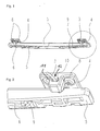
- the hinge has two tethers 4 which are connected to one another via a connecting part 5 are connected, the connecting part 5 being held rotatably in the holding cables 4.
- the holding parts 4 are provided with holes 11 which are used to receive Fastening screws 8 (Fig. 4) with which the hinge on a housing 1st or a panel can be attached.
- the holding parts 4 have guides 10, which for receiving one end 12 of Torsion springs 3, 6 serve.
- the ends 12 of these springs 3, 6 are axially displaceable held in the guides 10 of the holding parts 4.
- the connecting part 5 connecting the two holding parts 4 to one another is by means of screws 7 (FIG. 4) can be connected to a cover 2 (FIG. 3), with 5 Anchors 9 (FIG. 4) are arranged, in which the second ends 13 of the springs 3, 6 are fixed.
- the anchors 9 are in the end regions of the connecting part 5 arranged.
- the end regions 12, 13 of each spring 3, 6 are in each other opposite end regions of the hinge held or guided.
- the hinge is shown in a position in which one with a such a hinge-held lid (2) is in its closed position. Are there the two torsion springs 3, 6 largely relaxed.
Landscapes
- Engineering & Computer Science (AREA)
- Mechanical Engineering (AREA)
- Closing And Opening Devices For Wings, And Checks For Wings (AREA)
- Pivots And Pivotal Connections (AREA)
- Closures For Containers (AREA)
- Hinges (AREA)
- Mechanical Pencils And Projecting And Retracting Systems Therefor, And Multi-System Writing Instruments (AREA)
Abstract
Description
Claims (3)
- Scharnier zur Befestigung eines Deckels (2) an einem Gehäuse (1), wobei das Scharnier schwenkbar miteinander verbundenen Teile (4, 5) aufweist, von denen einer mit dem Gehäuse (1) und der andere mit dem Deckel (2) verbindbar ist, dadurch gekennzeichnet, daß mindestens eine Torsionsfeder (3, 6) vorgesehen ist, deren beide Enden (12, 13) in verschiedenen Teilen (4, 5) des Scharniers gehalten sind, wobei ein Endbereich (12) in einer Führung (10) axial verschiebbar gehalten und der andere Endbereich (13) in einer Verankerung (9) fixiert ist und die Verankerung (9) und die Führung (10) in verschiedenen Teilen (4, 5) des Scharniers angeordnet sind.
- Scharnier nach Anspruch 2, dadurch gekennzeichnet, daß in beiden Endbereichen des Scharnieres Führungen (10) in zwei Halteteile (4) angeordnet sind, die über einen mit diesen gelenkig verbundenen Verbindungsteil (5) miteinander verbunden sind, wobei in den Führungen (10) die einen Enden (12) von zwei Torsionsfedern (3, 6) verschiebbar gehalten sind, und die jeweils zweiten Enden (13) der Torsionsfedern (3, 6) in zwei im Verbindungsteil (5) des Scharnieres angeordneten Verankerungen (9) fixiert sind.
- Scharnier nach Anspruch 1 oder 2, dadurch gekennzeichnet, daß die Verankerung (9) und die Führung (10) für jede Torsionsfeder (3, 6) in einander entgegengesetzten Endbereichen des Scharnieres angeordnet sind.
Applications Claiming Priority (6)
| Application Number | Priority Date | Filing Date | Title |
|---|---|---|---|
| DE10049747 | 2000-09-29 | ||
| DE10049747 | 2000-09-29 | ||
| DE10049731 | 2000-09-30 | ||
| DE10049731 | 2000-09-30 | ||
| DE20842000U | 2000-12-15 | ||
| AT20842000 | 2000-12-15 |
Publications (2)
| Publication Number | Publication Date |
|---|---|
| EP1201859A1 true EP1201859A1 (de) | 2002-05-02 |
| EP1201859B1 EP1201859B1 (de) | 2006-06-07 |
Family
ID=27151352
Family Applications (1)
| Application Number | Title | Priority Date | Filing Date |
|---|---|---|---|
| EP01250340A Expired - Lifetime EP1201859B1 (de) | 2000-09-29 | 2001-09-27 | Scharnier zur Befestigung eines Deckels |
Country Status (3)
| Country | Link |
|---|---|
| EP (1) | EP1201859B1 (de) |
| AT (1) | ATE329114T1 (de) |
| DE (2) | DE50110021D1 (de) |
Citations (4)
| Publication number | Priority date | Publication date | Assignee | Title |
|---|---|---|---|---|
| GB590234A (en) * | 1945-03-17 | 1947-07-11 | Ernest John Leslie Brook | Improvements in spectacle and similar cases and other boxes having spring-loaded hinged lids |
| EP0412813A1 (de) * | 1989-08-11 | 1991-02-13 | Sugatsune Industrial Co., Ltd. | Montagevorrichtung für Toilettensitz und -deckel |
| EP0754832A1 (de) * | 1995-07-21 | 1997-01-22 | Moulinex S.A. | Scharnier für den Gehäusedeckel eines Kochgerätes |
| US5771540A (en) * | 1997-01-22 | 1998-06-30 | Torqmaster, Inc. | Equilibrated hinge with variable frictional torque |
-
2001
- 2001-09-27 AT AT01250340T patent/ATE329114T1/de active
- 2001-09-27 EP EP01250340A patent/EP1201859B1/de not_active Expired - Lifetime
- 2001-09-27 DE DE50110021T patent/DE50110021D1/de not_active Expired - Lifetime
- 2001-09-27 DE DE10148734A patent/DE10148734A1/de not_active Withdrawn
Patent Citations (4)
| Publication number | Priority date | Publication date | Assignee | Title |
|---|---|---|---|---|
| GB590234A (en) * | 1945-03-17 | 1947-07-11 | Ernest John Leslie Brook | Improvements in spectacle and similar cases and other boxes having spring-loaded hinged lids |
| EP0412813A1 (de) * | 1989-08-11 | 1991-02-13 | Sugatsune Industrial Co., Ltd. | Montagevorrichtung für Toilettensitz und -deckel |
| EP0754832A1 (de) * | 1995-07-21 | 1997-01-22 | Moulinex S.A. | Scharnier für den Gehäusedeckel eines Kochgerätes |
| US5771540A (en) * | 1997-01-22 | 1998-06-30 | Torqmaster, Inc. | Equilibrated hinge with variable frictional torque |
Also Published As
| Publication number | Publication date |
|---|---|
| ATE329114T1 (de) | 2006-06-15 |
| EP1201859B1 (de) | 2006-06-07 |
| DE10148734A1 (de) | 2002-05-16 |
| DE50110021D1 (de) | 2006-07-20 |
Similar Documents
| Publication | Publication Date | Title |
|---|---|---|
| DE602004007870T2 (de) | Scharniervorrichtung | |
| WO2018104199A1 (de) | Mehrgelenkscharnier | |
| DE29603811U1 (de) | Spannzwinge zur Einhandbedienung | |
| AT12190U1 (de) | Stellantrieb zum bewegen einer klappe eines möbels | |
| EP2201198B1 (de) | Griff, öse oder kleiderhaken mit befestigungsplatte und drehlager | |
| DE3408124C2 (de) | Verschluß für Sportschuhe, insbesondere Skischuhe oder Bergschuhe | |
| EP2987710A2 (de) | Universalhalter | |
| DE212022000073U1 (de) | Markise für Fahrzeug | |
| EP0789125A1 (de) | Tragteil für ein Verschlusselement, vorzugsweise für einen Türflügel einer Faltschiebetür | |
| AT517286A1 (de) | Überkopf-Gepäckfach für ein Flugzeug | |
| EP0157724A2 (de) | Transportvorrichtung für Drucker, insbesondere für Matrixdrucker | |
| DE69504601T2 (de) | Vorrichtung zur Verstellung der Länge und/oder der Spannung eines elastischen Seils | |
| DE112018005430T5 (de) | Scharnierarm-Dämpfungsmechanismus | |
| DE2653106A1 (de) | Klappenhalter | |
| EP3636104A2 (de) | Kopplungsvorrichtung für auszugsführung | |
| DE2850470C2 (de) | Zu öffnende Klappe, insbesondere Tankklappe | |
| EP1888370B1 (de) | Gurtöse | |
| EP1201859B1 (de) | Scharnier zur Befestigung eines Deckels | |
| DE3940491C1 (en) | Step flap for vehicle ramp - has adaptor with support to bear on ramp when latter pulled out for use | |
| AT526599B1 (de) | Anordnung zur Führung eines bewegbaren Möbelteils | |
| DE3120065A1 (de) | Moebelscharnier | |
| DE29813289U1 (de) | Laderaumtür | |
| DE3331668A1 (de) | Schwimmfaustsattel-scheibenbremse | |
| DE102005015541B4 (de) | Kraftfahrzeugscharnier für Türen und Klappen | |
| DE60107595T2 (de) | Verriegelungsvorrichtung an einer ladeklappe eines fahrzeugs |
Legal Events
| Date | Code | Title | Description |
|---|---|---|---|
| PUAI | Public reference made under article 153(3) epc to a published international application that has entered the european phase |
Free format text: ORIGINAL CODE: 0009012 |
|
| AK | Designated contracting states |
Kind code of ref document: A1 Designated state(s): AT BE CH CY DE DK ES FI FR GB GR IE IT LI LU MC NL PT SE TR |
|
| AX | Request for extension of the european patent |
Free format text: AL;LT;LV;MK;RO;SI |
|
| 17P | Request for examination filed |
Effective date: 20020516 |
|
| AKX | Designation fees paid |
Free format text: AT BE CH CY DE DK ES FI FR GB GR IE IT LI LU MC NL PT SE TR |
|
| 17Q | First examination report despatched |
Effective date: 20040729 |
|
| GRAP | Despatch of communication of intention to grant a patent |
Free format text: ORIGINAL CODE: EPIDOSNIGR1 |
|
| GRAS | Grant fee paid |
Free format text: ORIGINAL CODE: EPIDOSNIGR3 |
|
| GRAA | (expected) grant |
Free format text: ORIGINAL CODE: 0009210 |
|
| AK | Designated contracting states |
Kind code of ref document: B1 Designated state(s): AT BE CH CY DE DK ES FI FR GB GR IE IT LI LU MC NL PT SE TR |
|
| PG25 | Lapsed in a contracting state [announced via postgrant information from national office to epo] |
Ref country code: IT Free format text: LAPSE BECAUSE OF FAILURE TO SUBMIT A TRANSLATION OF THE DESCRIPTION OR TO PAY THE FEE WITHIN THE PRESCRIBED TIME-LIMIT;WARNING: LAPSES OF ITALIAN PATENTS WITH EFFECTIVE DATE BEFORE 2007 MAY HAVE OCCURRED AT ANY TIME BEFORE 2007. THE CORRECT EFFECTIVE DATE MAY BE DIFFERENT FROM THE ONE RECORDED. Effective date: 20060607 Ref country code: NL Free format text: LAPSE BECAUSE OF FAILURE TO SUBMIT A TRANSLATION OF THE DESCRIPTION OR TO PAY THE FEE WITHIN THE PRESCRIBED TIME-LIMIT Effective date: 20060607 Ref country code: FI Free format text: LAPSE BECAUSE OF FAILURE TO SUBMIT A TRANSLATION OF THE DESCRIPTION OR TO PAY THE FEE WITHIN THE PRESCRIBED TIME-LIMIT Effective date: 20060607 |
|
| REG | Reference to a national code |
Ref country code: GB Ref legal event code: FG4D Free format text: NOT ENGLISH |
|
| REG | Reference to a national code |
Ref country code: CH Ref legal event code: EP |
|
| REG | Reference to a national code |
Ref country code: IE Ref legal event code: FG4D Free format text: LANGUAGE OF EP DOCUMENT: GERMAN |
|
| REF | Corresponds to: |
Ref document number: 50110021 Country of ref document: DE Date of ref document: 20060720 Kind code of ref document: P |
|
| PG25 | Lapsed in a contracting state [announced via postgrant information from national office to epo] |
Ref country code: SE Free format text: LAPSE BECAUSE OF FAILURE TO SUBMIT A TRANSLATION OF THE DESCRIPTION OR TO PAY THE FEE WITHIN THE PRESCRIBED TIME-LIMIT Effective date: 20060907 Ref country code: DK Free format text: LAPSE BECAUSE OF FAILURE TO SUBMIT A TRANSLATION OF THE DESCRIPTION OR TO PAY THE FEE WITHIN THE PRESCRIBED TIME-LIMIT Effective date: 20060907 |
|
| PG25 | Lapsed in a contracting state [announced via postgrant information from national office to epo] |
Ref country code: ES Free format text: LAPSE BECAUSE OF FAILURE TO SUBMIT A TRANSLATION OF THE DESCRIPTION OR TO PAY THE FEE WITHIN THE PRESCRIBED TIME-LIMIT Effective date: 20060918 |
|
| PG25 | Lapsed in a contracting state [announced via postgrant information from national office to epo] |
Ref country code: MC Free format text: LAPSE BECAUSE OF NON-PAYMENT OF DUE FEES Effective date: 20060930 |
|
| GBT | Gb: translation of ep patent filed (gb section 77(6)(a)/1977) |
Effective date: 20060907 |
|
| PG25 | Lapsed in a contracting state [announced via postgrant information from national office to epo] |
Ref country code: PT Free format text: LAPSE BECAUSE OF FAILURE TO SUBMIT A TRANSLATION OF THE DESCRIPTION OR TO PAY THE FEE WITHIN THE PRESCRIBED TIME-LIMIT Effective date: 20061107 |
|
| NLV1 | Nl: lapsed or annulled due to failure to fulfill the requirements of art. 29p and 29m of the patents act | ||
| ET | Fr: translation filed | ||
| PLBE | No opposition filed within time limit |
Free format text: ORIGINAL CODE: 0009261 |
|
| STAA | Information on the status of an ep patent application or granted ep patent |
Free format text: STATUS: NO OPPOSITION FILED WITHIN TIME LIMIT |
|
| 26N | No opposition filed |
Effective date: 20070308 |
|
| PG25 | Lapsed in a contracting state [announced via postgrant information from national office to epo] |
Ref country code: GR Free format text: LAPSE BECAUSE OF FAILURE TO SUBMIT A TRANSLATION OF THE DESCRIPTION OR TO PAY THE FEE WITHIN THE PRESCRIBED TIME-LIMIT Effective date: 20060908 |
|
| PG25 | Lapsed in a contracting state [announced via postgrant information from national office to epo] |
Ref country code: TR Free format text: LAPSE BECAUSE OF FAILURE TO SUBMIT A TRANSLATION OF THE DESCRIPTION OR TO PAY THE FEE WITHIN THE PRESCRIBED TIME-LIMIT Effective date: 20060607 Ref country code: LU Free format text: LAPSE BECAUSE OF NON-PAYMENT OF DUE FEES Effective date: 20060927 |
|
| PG25 | Lapsed in a contracting state [announced via postgrant information from national office to epo] |
Ref country code: CY Free format text: LAPSE BECAUSE OF FAILURE TO SUBMIT A TRANSLATION OF THE DESCRIPTION OR TO PAY THE FEE WITHIN THE PRESCRIBED TIME-LIMIT Effective date: 20060607 |
|
| PGFP | Annual fee paid to national office [announced via postgrant information from national office to epo] |
Ref country code: CH Payment date: 20110810 Year of fee payment: 11 |
|
| PGFP | Annual fee paid to national office [announced via postgrant information from national office to epo] |
Ref country code: IE Payment date: 20120613 Year of fee payment: 12 |
|
| PGFP | Annual fee paid to national office [announced via postgrant information from national office to epo] |
Ref country code: GB Payment date: 20120807 Year of fee payment: 12 |
|
| PGFP | Annual fee paid to national office [announced via postgrant information from national office to epo] |
Ref country code: FR Payment date: 20120904 Year of fee payment: 12 Ref country code: BE Payment date: 20120814 Year of fee payment: 12 |
|
| PGFP | Annual fee paid to national office [announced via postgrant information from national office to epo] |
Ref country code: AT Payment date: 20120816 Year of fee payment: 12 |
|
| BERE | Be: lapsed |
Owner name: VAILLANT G.M.B.H. Effective date: 20130930 |
|
| REG | Reference to a national code |
Ref country code: CH Ref legal event code: PL |
|
| REG | Reference to a national code |
Ref country code: AT Ref legal event code: MM01 Ref document number: 329114 Country of ref document: AT Kind code of ref document: T Effective date: 20130927 |
|
| GBPC | Gb: european patent ceased through non-payment of renewal fee |
Effective date: 20130927 |
|
| REG | Reference to a national code |
Ref country code: FR Ref legal event code: ST Effective date: 20140530 |
|
| REG | Reference to a national code |
Ref country code: IE Ref legal event code: MM4A |
|
| PG25 | Lapsed in a contracting state [announced via postgrant information from national office to epo] |
Ref country code: GB Free format text: LAPSE BECAUSE OF NON-PAYMENT OF DUE FEES Effective date: 20130927 Ref country code: LI Free format text: LAPSE BECAUSE OF NON-PAYMENT OF DUE FEES Effective date: 20130930 Ref country code: CH Free format text: LAPSE BECAUSE OF NON-PAYMENT OF DUE FEES Effective date: 20130930 Ref country code: IE Free format text: LAPSE BECAUSE OF NON-PAYMENT OF DUE FEES Effective date: 20130927 Ref country code: BE Free format text: LAPSE BECAUSE OF NON-PAYMENT OF DUE FEES Effective date: 20130930 |
|
| PG25 | Lapsed in a contracting state [announced via postgrant information from national office to epo] |
Ref country code: FR Free format text: LAPSE BECAUSE OF NON-PAYMENT OF DUE FEES Effective date: 20130930 Ref country code: AT Free format text: LAPSE BECAUSE OF NON-PAYMENT OF DUE FEES Effective date: 20130927 |
|
| PGFP | Annual fee paid to national office [announced via postgrant information from national office to epo] |
Ref country code: DE Payment date: 20180903 Year of fee payment: 18 |
|
| REG | Reference to a national code |
Ref country code: DE Ref legal event code: R119 Ref document number: 50110021 Country of ref document: DE |
|
| PG25 | Lapsed in a contracting state [announced via postgrant information from national office to epo] |
Ref country code: DE Free format text: LAPSE BECAUSE OF NON-PAYMENT OF DUE FEES Effective date: 20200401 |