EP1201783A1 - Verfahren und Vorrichtung zum Führen eines Metallbandes, insbesondere eines Stahlbandes, durch einen Beschichtungsbehälter - Google Patents
Verfahren und Vorrichtung zum Führen eines Metallbandes, insbesondere eines Stahlbandes, durch einen Beschichtungsbehälter Download PDFInfo
- Publication number
- EP1201783A1 EP1201783A1 EP01122810A EP01122810A EP1201783A1 EP 1201783 A1 EP1201783 A1 EP 1201783A1 EP 01122810 A EP01122810 A EP 01122810A EP 01122810 A EP01122810 A EP 01122810A EP 1201783 A1 EP1201783 A1 EP 1201783A1
- Authority
- EP
- European Patent Office
- Prior art keywords
- metal
- strip
- molten metal
- coating container
- container
- Prior art date
- Legal status (The legal status is an assumption and is not a legal conclusion. Google has not performed a legal analysis and makes no representation as to the accuracy of the status listed.)
- Granted
Links
- 239000011248 coating agent Substances 0.000 title claims abstract description 32
- 238000000576 coating method Methods 0.000 title claims abstract description 32
- 229910000831 Steel Inorganic materials 0.000 title claims abstract description 14
- 239000010959 steel Substances 0.000 title claims abstract description 14
- 238000000034 method Methods 0.000 title claims abstract description 9
- 239000002184 metal Substances 0.000 title claims description 77
- 229910052751 metal Inorganic materials 0.000 title claims description 77
- 239000000155 melt Substances 0.000 claims abstract description 8
- 230000006698 induction Effects 0.000 claims description 9
- 238000000465 moulding Methods 0.000 abstract 2
- HCHKCACWOHOZIP-UHFFFAOYSA-N Zinc Chemical compound [Zn] HCHKCACWOHOZIP-UHFFFAOYSA-N 0.000 description 3
- 229910052725 zinc Inorganic materials 0.000 description 3
- 239000011701 zinc Substances 0.000 description 3
- 230000001154 acute effect Effects 0.000 description 2
- 230000000694 effects Effects 0.000 description 2
- 230000002411 adverse Effects 0.000 description 1
- 230000015572 biosynthetic process Effects 0.000 description 1
- 230000005672 electromagnetic field Effects 0.000 description 1
- 239000007788 liquid Substances 0.000 description 1
- 229910001338 liquidmetal Inorganic materials 0.000 description 1
- 238000007747 plating Methods 0.000 description 1
- 238000007789 sealing Methods 0.000 description 1
Images

Classifications
-
- C—CHEMISTRY; METALLURGY
- C23—COATING METALLIC MATERIAL; COATING MATERIAL WITH METALLIC MATERIAL; CHEMICAL SURFACE TREATMENT; DIFFUSION TREATMENT OF METALLIC MATERIAL; COATING BY VACUUM EVAPORATION, BY SPUTTERING, BY ION IMPLANTATION OR BY CHEMICAL VAPOUR DEPOSITION, IN GENERAL; INHIBITING CORROSION OF METALLIC MATERIAL OR INCRUSTATION IN GENERAL
- C23C—COATING METALLIC MATERIAL; COATING MATERIAL WITH METALLIC MATERIAL; SURFACE TREATMENT OF METALLIC MATERIAL BY DIFFUSION INTO THE SURFACE, BY CHEMICAL CONVERSION OR SUBSTITUTION; COATING BY VACUUM EVAPORATION, BY SPUTTERING, BY ION IMPLANTATION OR BY CHEMICAL VAPOUR DEPOSITION, IN GENERAL
- C23C2/00—Hot-dipping or immersion processes for applying the coating material in the molten state without affecting the shape; Apparatus therefor
- C23C2/14—Removing excess of molten coatings; Controlling or regulating the coating thickness
- C23C2/24—Removing excess of molten coatings; Controlling or regulating the coating thickness using magnetic or electric fields
-
- C—CHEMISTRY; METALLURGY
- C23—COATING METALLIC MATERIAL; COATING MATERIAL WITH METALLIC MATERIAL; CHEMICAL SURFACE TREATMENT; DIFFUSION TREATMENT OF METALLIC MATERIAL; COATING BY VACUUM EVAPORATION, BY SPUTTERING, BY ION IMPLANTATION OR BY CHEMICAL VAPOUR DEPOSITION, IN GENERAL; INHIBITING CORROSION OF METALLIC MATERIAL OR INCRUSTATION IN GENERAL
- C23C—COATING METALLIC MATERIAL; COATING MATERIAL WITH METALLIC MATERIAL; SURFACE TREATMENT OF METALLIC MATERIAL BY DIFFUSION INTO THE SURFACE, BY CHEMICAL CONVERSION OR SUBSTITUTION; COATING BY VACUUM EVAPORATION, BY SPUTTERING, BY ION IMPLANTATION OR BY CHEMICAL VAPOUR DEPOSITION, IN GENERAL
- C23C2/00—Hot-dipping or immersion processes for applying the coating material in the molten state without affecting the shape; Apparatus therefor
- C23C2/003—Apparatus
- C23C2/0034—Details related to elements immersed in bath
- C23C2/00348—Fixed work supports or guides
-
- C—CHEMISTRY; METALLURGY
- C23—COATING METALLIC MATERIAL; COATING MATERIAL WITH METALLIC MATERIAL; CHEMICAL SURFACE TREATMENT; DIFFUSION TREATMENT OF METALLIC MATERIAL; COATING BY VACUUM EVAPORATION, BY SPUTTERING, BY ION IMPLANTATION OR BY CHEMICAL VAPOUR DEPOSITION, IN GENERAL; INHIBITING CORROSION OF METALLIC MATERIAL OR INCRUSTATION IN GENERAL
- C23C—COATING METALLIC MATERIAL; COATING MATERIAL WITH METALLIC MATERIAL; SURFACE TREATMENT OF METALLIC MATERIAL BY DIFFUSION INTO THE SURFACE, BY CHEMICAL CONVERSION OR SUBSTITUTION; COATING BY VACUUM EVAPORATION, BY SPUTTERING, BY ION IMPLANTATION OR BY CHEMICAL VAPOUR DEPOSITION, IN GENERAL
- C23C2/00—Hot-dipping or immersion processes for applying the coating material in the molten state without affecting the shape; Apparatus therefor
- C23C2/003—Apparatus
- C23C2/0035—Means for continuously moving substrate through, into or out of the bath
-
- C—CHEMISTRY; METALLURGY
- C23—COATING METALLIC MATERIAL; COATING MATERIAL WITH METALLIC MATERIAL; CHEMICAL SURFACE TREATMENT; DIFFUSION TREATMENT OF METALLIC MATERIAL; COATING BY VACUUM EVAPORATION, BY SPUTTERING, BY ION IMPLANTATION OR BY CHEMICAL VAPOUR DEPOSITION, IN GENERAL; INHIBITING CORROSION OF METALLIC MATERIAL OR INCRUSTATION IN GENERAL
- C23C—COATING METALLIC MATERIAL; COATING MATERIAL WITH METALLIC MATERIAL; SURFACE TREATMENT OF METALLIC MATERIAL BY DIFFUSION INTO THE SURFACE, BY CHEMICAL CONVERSION OR SUBSTITUTION; COATING BY VACUUM EVAPORATION, BY SPUTTERING, BY ION IMPLANTATION OR BY CHEMICAL VAPOUR DEPOSITION, IN GENERAL
- C23C2/00—Hot-dipping or immersion processes for applying the coating material in the molten state without affecting the shape; Apparatus therefor
- C23C2/003—Apparatus
- C23C2/0036—Crucibles
- C23C2/00361—Crucibles characterised by structures including means for immersing or extracting the substrate through confining wall area
- C23C2/00362—Details related to seals, e.g. magnetic means
Definitions
- the invention relates to a method and a device for guiding a metal strip, in particular a steel strip, through a coating container from bottom up, the metal band over a surrounding the input channel Induction field, which prevents the molten metal from escaping, guided in the molten metal coated and stripped over the molten metal mirror.
- Such a method based on zinc melt is known from EP 0 630 421 B1 known.
- a steel strip is passed vertically through the zinc bath to create a Perform surface finishing by plating metal on the steel belt Keeps hanging.
- the sealing of the weld pool at the inlet opening, i.e. in the Input channel is through an electromagnetic field.
- a deformation occurs of the steel strip due to the induced magnetic fields. This deformation leads to an S-like formation of the metal strip cross section of the steel band on the inner walls of the entrance channel. Furthermore, this deformation of the steel strip in the downstream stripping nozzle undesirable because different layer thicknesses of the molten metal can occur.
- the invention has for its object the disadvantageous deformation of the steel strip to prevent, so the adverse effects of wall contact and different Layer thicknesses of the metal coating can not occur.
- the object is achieved according to the invention in that in the input channel and metal strip continuously guided through the molten metal one or more directed flows generated in the molten metal from at least an arc is straightened straight and flat and redirected into the vertical.
- This procedure creates a liquid metal cushion that is non-contact Redirection enabled. This can cause deformation of the metal strip be realigned within the coating container so that the deformation undone and when stripping a straightened flat metal tape is present. As a result, the previous tours on roles are not needed more.
- the metal strip is in the molten metal is diverted into the vertical by two or more directed currents, wherein a first flow and a second subsequent flow by one each Bow is deflected with a second, opposite curvature. Thereby the metal strip can be fed vertically and removed vertically.
- An improvement provides that the flow of molten metal along a Form wall is generated. This forms between the curved mold wall and a flow from the metal strip, which flat deforms the metal strip again.
- the metal strip can also be guided in such a way that the Flow of molten metal around opposing mold walls of the same Curvature is passed through, between which the metal strip is guided. Thereby Effects can also be achieved that deform the metal band flat.
- a device for guiding a metal strip, in particular a steel strip, in a coating container, the metal strip being opened through a bottom Input channel can be passed from bottom to top through the molten metal and the input channel is surrounded by an induction coil device, which prevents the molten metal from escaping through the inlet channel, triggers the task according to the invention in that at least in the coating container a mold wall determining the strip travel is arranged and that the Metal melt from a premelting tank by means of a melt pump the mold wall can be conveyed under pressure against the bent metal band. As a result, the metal strip becomes flat as desired and loses its S-like cross-sectional shape.
- this idea is carried out in such a way that the mold wall on one Holder in a recess in the wall of the coating container into the Belt travel is enough. As a result, the molten metal can go to the strip path Pressure to be introduced.
- brackets opposite sides of the coating container against each other in height are offset. This can cause the metal strip to bend and bend back to achieve flatness.
- brackets in their Inside each form flow channels for the molten metal.
- the molten metal can thereby act on the metal strip to a selected length.
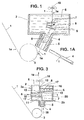
- the entrance channel is at an acute angle to the vertical
- the induction field prevents the molten metal 6, e.g. liquid zinc, am Leak out of the inlet channel 4 open at the bottom.
- the metal strip 1 takes an S-like shape in the input channel 4, which is due to the induction field.
- the metal strip 1 is then in the molten metal 6 by two or more against the surface of the metal strip 1 directed flows 7, 8 and / or 9 in deflected the vertical, a first flow 7 and a second subsequent one Flow 8 around an arc 11 and 12 with a second opposite Curvature are performed (Fig. 3).
- the flows 7 and 8 are each along a Form wall 13 generated.
- the flows 7 and 8 can merge (Fig. 3), the flow 7 of molten metal 6 along the mold wall 13 and the Metal strip 1 is generated.
- the coating container 2 (FIGS. 2 and 3) at least one is the belt path 1a determining mold wall 13 arranged.
- the molten metal 6 is made from a Premelt container 14 by means of a melt pump 15 through the mold wall 13 sprayed under pressure against the bent metal strip 1.
- the molded wall 13 is on a holder 16 in a recess in the wall 20 of the coating container 2 each formed up to the belt path 1a.
- such a mold wall 13 is formed on the bracket 16.
- the brackets 16 of the opposite sides 2a, 2b of the coating container 2 are mutually offset in height (Fig. 3).
- the Brackets 16 each form flow channels 17 for the molten metal in their interior 16a 6th
- the molten metal 6 is from the premelt tank 14 via the melt pump 15, the holder 16 and the coating container 2 and back in the Premelt container 14 guided in the circuit.
Landscapes
- Chemical & Material Sciences (AREA)
- Chemical Kinetics & Catalysis (AREA)
- Engineering & Computer Science (AREA)
- Materials Engineering (AREA)
- Mechanical Engineering (AREA)
- Metallurgy (AREA)
- Organic Chemistry (AREA)
- Coating With Molten Metal (AREA)
Abstract
Description
- Fig. 1
- einen Querschnitt durch die Beschichtungsanlage mit einem schrägen Eingangskanal,
- Fig. 1A
- einen Querschnitt durch den Bereich des Eingangskanals,
- Fig. 2
- einen Querschnitt durch die Beschichtungsanlage mit einem ersten Ausführungsbeispiel und
- Fig. 3
- einen Querschnitt durch die Beschichtungsanlage für ein zweites Ausführungsbeispiel.
- 1
- Metallband
- 1a
- Bandlaufweg
- 2
- Beschichtungsbehälter
- 2a
- Seite des Beschichtungsbehälters
- 2b
- Seite des Beschichtungsbehälters
- 3
- Umlenkrolle
- 4
- Eingangskanal
- 5
- Induktionsspule
- 6
- Metallschmelze
- 7
- (erste) Strömung
- 8
- (zweite) Strömung
- 9
- Strömung
- 10
- Abstreifer
- 11
- Bogen
- 12
- Bogen
- 13
- Formwand
- 14
- Vorschmelzbehälter
- 15
- Schmelzenpumpe
- 16
- Halterung
- 16a
- Inneres
- 17
- Strömungskanal
- 18
- senkrechter Bandeinlauf
- 19
- senkrechter Bandauslauf
- 20
- Wandung
Claims (11)
- Verfahren zum Führen eines Metallbandes, insbesondere eines Stahlbandes, durch einen Beschichtungsbehälter von unten nach oben, wobei das Metallband über ein den Eingangskanal umgebendes Induktionsfeld, das die Metallschmelze am Auslaufen hindert, geführt, in der Metallschmelze beschichtet und über dem Metallschmelzenspiegel abgestreift wird,
dadurch gekennzeichnet, dass das in dem Eingangskanal und durch die Metallschmelze kontinuierlich geführte Metallband durch eine oder mehrere in der Metallschmelze erzeugte , gerichtete Strömungen aus zumindest einem Bogen gerade und plan gerichtet und in die Vertikale umgelenkt wird. - Verfahren nach Anspruch 1,
dadurch gekennzeichnet, dass das Metallband in der Metallschmelze durch zwei oder mehrere gerichtete Strömungen in die Vertikale umgelenkt wird, wobei eine erste Strömung und eine zweite anschließende Strömung um jeweils einen Bogen mit einer zweiten, entgegengesetzten Krümmung umgelenkt wird. - Verfahren nach einem der Ansprüche 1 oder,
dadurch gekennzeichnet, dass die Strömung aus Metallschmelze entlang einer Formwand erzeugt wird. - Verfahren nach einem der Ansprüche 1 bis 3,
dadurch gekennzeichnet, dass die Strömung aus Metallschmelze um einander gegenüberliegenden Formwänden gleicher Krümmung hindurchgeleitet wird, zwischen denen das Metallband geführt wird. - Vorrichtung zur Führung eines Metallbandes, insbesondere eines Stahlbandes, in einem Beschichtungsbehälter, wobei das Metallband durch einen unten offenen Eingangskanal hindurch von unten nach oben durch Metallschmelze führbar ist und wobei der Eingangskanal mit einer Induktionsspulen-Einrichtung umgeben ist, die das Auslaufen der Metallschmelze durch den Eingangskanal verhindert,
dadurch gekennzeichnet, dass im Beschichtungsbehälter (2) zumindest eine den Bandlaufweg (1a) bestimmende Formwand (13) angeordnet ist und dass die Metallschmelze (6) aus einem Vorschmelzbehälter (14) mittels einer Schmelzenpumpe (15) durch die Formwand (13) hindurch gegen das gebogene Metallband (1) unter Druck förderbar ist. - Vorrichtung nach Anspruch 5,
dadurch gekennzeichnet, dass die Formwand (13) an einer Halterung (16) in einer Ausnehmung der Wandung (20) des Beschichtungsbehälters (2) bis in den Bandlaufweg (1a) reicht. - Vorrichtung nach einem der Ansprüche 5 oder 6,
dadurch gekennzeichnet, dass mehrere Formwände (13) an gegenüberliegenden Seiten (2a; 2b) des Beschichtungsbehälters (2) mit sich jeweils in den Bandlaufweg (1a) erstrekkenden Halterungen (16) vorgesehen sind. - Vorrichtung nach Anspruch 7,
dadurch gekennzeichnet, dass die Halterungen (16) der sich gegenüberliegenden Seiten (2a; 2b) des Beschichtungsbehälters (2) in der Höhe gegeneinander versetzt sind. - Vorrichtung nach einem der Ansprüche 5 bis 8,
dadurch gekennzeichnet, dass die Halterungen (16) in ihrem Inneren (16a) jeweils Strömungskanäle (17) für die Metallschmelze (6) bilden. - Vorrichtung nach einem der Ansprüche 5 bis 9,
dadurch gekennzeichnet, dass bei mehreren sich gegenüberliegenden, in der Höhe versetzten Halterungen (16) der senkrechte Bandeinlauf (18) zum senkrechten Bandauslauf (19) seitlich versetzt ist. - Vorrichtung nach einem der Ansprüche 5 bis 10,
dadurch gekennzeichnet, dass die Metallschmelze (6) vom Vorschmelzbehälter (14) über die Schmelzenpumpe (15), die Halterung (16) und den Beschichtungsbehälter (2) und zurück in den Vorschmelzbehälter (14) im Kreislauf geführt ist.
Applications Claiming Priority (2)
| Application Number | Priority Date | Filing Date | Title |
|---|---|---|---|
| DE10052096 | 2000-10-20 | ||
| DE10052096A DE10052096A1 (de) | 2000-10-20 | 2000-10-20 | Verfahren und Vorrichtung zum Führen eines Metallbandes, insbesondere eines Stahlbandes, durch einen Beschichtungsbehälter |
Publications (2)
| Publication Number | Publication Date |
|---|---|
| EP1201783A1 true EP1201783A1 (de) | 2002-05-02 |
| EP1201783B1 EP1201783B1 (de) | 2003-07-23 |
Family
ID=7660485
Family Applications (1)
| Application Number | Title | Priority Date | Filing Date |
|---|---|---|---|
| EP01122810A Expired - Lifetime EP1201783B1 (de) | 2000-10-20 | 2001-09-22 | Verfahren und Vorrichtung zum Führen eines Metallbandes, insbesondere eines Stahlbandes, durch einen Beschichtungsbehälter |
Country Status (3)
| Country | Link |
|---|---|
| EP (1) | EP1201783B1 (de) |
| AT (1) | ATE245716T1 (de) |
| DE (2) | DE10052096A1 (de) |
Families Citing this family (1)
| Publication number | Priority date | Publication date | Assignee | Title |
|---|---|---|---|---|
| DE102017223778B4 (de) * | 2017-12-22 | 2022-06-09 | Thyssenkrupp Ag | Barometrische Flüssigkeitsschleusen und Verfahren zum kontinuierlichen Einschleusen oder Ausschleusen von Materialbändern |
Citations (3)
| Publication number | Priority date | Publication date | Assignee | Title |
|---|---|---|---|---|
| US4971842A (en) * | 1987-02-27 | 1990-11-20 | Rasmet Ky | Method for controlling the thickness of an intermetallic layer on a continuous steel product in a continuous hot-dip galvanizing process |
| WO1993018198A1 (de) * | 1992-03-13 | 1993-09-16 | Mannesmann Ag | Verfahren zum beschichten der oberfläche von strangförmigem gut |
| US5958518A (en) * | 1998-01-29 | 1999-09-28 | Sippola; Perti J. | Method of producing hot-dip zinc coated steel sheet free of dross pick-up defects on coating and associated apparatus |
-
2000
- 2000-10-20 DE DE10052096A patent/DE10052096A1/de not_active Withdrawn
-
2001
- 2001-09-22 AT AT01122810T patent/ATE245716T1/de not_active IP Right Cessation
- 2001-09-22 EP EP01122810A patent/EP1201783B1/de not_active Expired - Lifetime
- 2001-09-22 DE DE50100404T patent/DE50100404D1/de not_active Expired - Fee Related
Patent Citations (3)
| Publication number | Priority date | Publication date | Assignee | Title |
|---|---|---|---|---|
| US4971842A (en) * | 1987-02-27 | 1990-11-20 | Rasmet Ky | Method for controlling the thickness of an intermetallic layer on a continuous steel product in a continuous hot-dip galvanizing process |
| WO1993018198A1 (de) * | 1992-03-13 | 1993-09-16 | Mannesmann Ag | Verfahren zum beschichten der oberfläche von strangförmigem gut |
| US5958518A (en) * | 1998-01-29 | 1999-09-28 | Sippola; Perti J. | Method of producing hot-dip zinc coated steel sheet free of dross pick-up defects on coating and associated apparatus |
Also Published As
| Publication number | Publication date |
|---|---|
| DE10052096A1 (de) | 2002-05-02 |
| ATE245716T1 (de) | 2003-08-15 |
| EP1201783B1 (de) | 2003-07-23 |
| DE50100404D1 (de) | 2003-08-28 |
Similar Documents
| Publication | Publication Date | Title |
|---|---|---|
| EP0630421B1 (de) | Vorrichtung zum beschichten der oberfläche von stahlband | |
| WO1994013850A1 (de) | Verfahren und vorrichtung zum beschichten der oberfläche von strangförmigem gut | |
| DE2311473A1 (de) | Vorrichtung und verfahren zur feuerverzinkung von rohrmaterial | |
| EP1201783B1 (de) | Verfahren und Vorrichtung zum Führen eines Metallbandes, insbesondere eines Stahlbandes, durch einen Beschichtungsbehälter | |
| EP0630420B1 (de) | Verfahren zum mehrlagigen beschichten von strangförmigem gut | |
| DE3040503C2 (de) | ||
| EP0630711B1 (de) | Eintauchausguss | |
| DE2656524C3 (de) | Verfahren zum einseitigen Beschichten eines Metallbandes mit schmelzflüssigem Metall | |
| EP1483423B1 (de) | Vorrichtung zur schmelztauchbeschichtung von metallsträngen | |
| EP0490034A1 (de) | Verfahren und Vorrichtung zur Herstellung eines endabmessungsnahen Metallbandes | |
| EP0080724B1 (de) | Vorrichtung zum kontinuierlichen Tauchverzinken von metallischem Draht oder Band | |
| EP1483424B1 (de) | Vorrichtung zur schmelztauchbeschichtung von metallsträngen | |
| DE3020806A1 (de) | Verfahren und vorrichtung zum einseitigen plattieren eines stahlbandes | |
| DE10254306A1 (de) | Verfahren und Vorrichtung zur Schmelztauchbeschichtung eines Metallstranges | |
| EP1215300B1 (de) | Abstreifer für Schmelztauchverfahren | |
| DE2450365B2 (de) | Verfahren und Vorrichtung zum kontinuierlichen Abschrecken eines elektrolytisch verzinnten und aufgeschmolzenen Stahlbandes | |
| EP0070913A1 (de) | Gefäss zur Behandlung von schmelzflüssigen Metallen | |
| EP3561133B1 (de) | Vorrichtung und verfahren zum schmelztauchbeschichten eines metallbandes mit mindestens zwei schichten | |
| DE60303630T2 (de) | Vorrichtung sowie Verfahren zur Erzeugung von dünnem Bimetallband mit einer 2-Rollen-Giessvorrichtung | |
| WO2018228663A1 (de) | Vorrichtung und verfahren zur separierung von gasatmosphären | |
| DE4337237A1 (de) | Kunststoff-Spritzgießverfahren mit Gaseinleitung | |
| DE3047979C2 (de) | ||
| EP1390551B1 (de) | Verfahren und vorrichtung zum thermischen behandeln von metallsträngen, insbesondere von stahlband | |
| DE10014868A1 (de) | Verfahren und Einrichtung zum Schmelztauchbeschichten von Metallsträngen, insbesondere von Stahlband | |
| DE10216867A1 (de) | Verfahren und Vorrichtung zum Beschichten der Oberfläche von strangförmigem metallischen Gut |
Legal Events
| Date | Code | Title | Description |
|---|---|---|---|
| PUAI | Public reference made under article 153(3) epc to a published international application that has entered the european phase |
Free format text: ORIGINAL CODE: 0009012 |
|
| 17P | Request for examination filed |
Effective date: 20010922 |
|
| AK | Designated contracting states |
Kind code of ref document: A1 Designated state(s): AT BE CH CY DE DK ES FI FR GB GR IE IT LI LU MC NL PT SE TR |
|
| AX | Request for extension of the european patent |
Free format text: AL;LT;LV;MK;RO;SI |
|
| AKX | Designation fees paid |
Free format text: AT BE CH CY DE DK ES FI FR GB GR IE IT LI LU MC NL PT SE TR |
|
| GRAH | Despatch of communication of intention to grant a patent |
Free format text: ORIGINAL CODE: EPIDOS IGRA |
|
| GRAH | Despatch of communication of intention to grant a patent |
Free format text: ORIGINAL CODE: EPIDOS IGRA |
|
| GRAA | (expected) grant |
Free format text: ORIGINAL CODE: 0009210 |
|
| AK | Designated contracting states |
Designated state(s): AT BE CH CY DE DK ES FI FR GB GR IE IT LI LU MC NL PT SE TR |
|
| PG25 | Lapsed in a contracting state [announced via postgrant information from national office to epo] |
Ref country code: TR Free format text: LAPSE BECAUSE OF FAILURE TO SUBMIT A TRANSLATION OF THE DESCRIPTION OR TO PAY THE FEE WITHIN THE PRESCRIBED TIME-LIMIT Effective date: 20030723 Ref country code: NL Free format text: LAPSE BECAUSE OF FAILURE TO SUBMIT A TRANSLATION OF THE DESCRIPTION OR TO PAY THE FEE WITHIN THE PRESCRIBED TIME-LIMIT Effective date: 20030723 Ref country code: IT Free format text: LAPSE BECAUSE OF FAILURE TO SUBMIT A TRANSLATION OF THE DESCRIPTION OR TO PAY THE FEE WITHIN THE PRESCRIBED TIME-LIMIT;WARNING: LAPSES OF ITALIAN PATENTS WITH EFFECTIVE DATE BEFORE 2007 MAY HAVE OCCURRED AT ANY TIME BEFORE 2007. THE CORRECT EFFECTIVE DATE MAY BE DIFFERENT FROM THE ONE RECORDED. Effective date: 20030723 Ref country code: IE Free format text: LAPSE BECAUSE OF FAILURE TO SUBMIT A TRANSLATION OF THE DESCRIPTION OR TO PAY THE FEE WITHIN THE PRESCRIBED TIME-LIMIT Effective date: 20030723 Ref country code: GB Free format text: LAPSE BECAUSE OF FAILURE TO SUBMIT A TRANSLATION OF THE DESCRIPTION OR TO PAY THE FEE WITHIN THE PRESCRIBED TIME-LIMIT Effective date: 20030723 Ref country code: FR Free format text: LAPSE BECAUSE OF FAILURE TO SUBMIT A TRANSLATION OF THE DESCRIPTION OR TO PAY THE FEE WITHIN THE PRESCRIBED TIME-LIMIT Effective date: 20030723 Ref country code: FI Free format text: LAPSE BECAUSE OF FAILURE TO SUBMIT A TRANSLATION OF THE DESCRIPTION OR TO PAY THE FEE WITHIN THE PRESCRIBED TIME-LIMIT Effective date: 20030723 Ref country code: ES Free format text: LAPSE BECAUSE OF FAILURE TO SUBMIT A TRANSLATION OF THE DESCRIPTION OR TO PAY THE FEE WITHIN THE PRESCRIBED TIME-LIMIT Effective date: 20030723 |
|
| REG | Reference to a national code |
Ref country code: GB Ref legal event code: FG4D Free format text: NOT ENGLISH |
|
| REG | Reference to a national code |
Ref country code: CH Ref legal event code: EP |
|
| REG | Reference to a national code |
Ref country code: IE Ref legal event code: FG4D Free format text: GERMAN |
|
| REF | Corresponds to: |
Ref document number: 50100404 Country of ref document: DE Date of ref document: 20030828 Kind code of ref document: P |
|
| PG25 | Lapsed in a contracting state [announced via postgrant information from national office to epo] |
Ref country code: LU Free format text: LAPSE BECAUSE OF NON-PAYMENT OF DUE FEES Effective date: 20030922 Ref country code: CY Free format text: LAPSE BECAUSE OF FAILURE TO SUBMIT A TRANSLATION OF THE DESCRIPTION OR TO PAY THE FEE WITHIN THE PRESCRIBED TIME-LIMIT Effective date: 20030922 Ref country code: AT Free format text: LAPSE BECAUSE OF NON-PAYMENT OF DUE FEES Effective date: 20030922 |
|
| PG25 | Lapsed in a contracting state [announced via postgrant information from national office to epo] |
Ref country code: MC Free format text: LAPSE BECAUSE OF NON-PAYMENT OF DUE FEES Effective date: 20030930 Ref country code: BE Free format text: LAPSE BECAUSE OF NON-PAYMENT OF DUE FEES Effective date: 20030930 |
|
| PG25 | Lapsed in a contracting state [announced via postgrant information from national office to epo] |
Ref country code: SE Free format text: LAPSE BECAUSE OF FAILURE TO SUBMIT A TRANSLATION OF THE DESCRIPTION OR TO PAY THE FEE WITHIN THE PRESCRIBED TIME-LIMIT Effective date: 20031023 Ref country code: GR Free format text: LAPSE BECAUSE OF FAILURE TO SUBMIT A TRANSLATION OF THE DESCRIPTION OR TO PAY THE FEE WITHIN THE PRESCRIBED TIME-LIMIT Effective date: 20031023 Ref country code: DK Free format text: LAPSE BECAUSE OF FAILURE TO SUBMIT A TRANSLATION OF THE DESCRIPTION OR TO PAY THE FEE WITHIN THE PRESCRIBED TIME-LIMIT Effective date: 20031023 |
|
| NLV1 | Nl: lapsed or annulled due to failure to fulfill the requirements of art. 29p and 29m of the patents act | ||
| PG25 | Lapsed in a contracting state [announced via postgrant information from national office to epo] |
Ref country code: PT Free format text: LAPSE BECAUSE OF FAILURE TO SUBMIT A TRANSLATION OF THE DESCRIPTION OR TO PAY THE FEE WITHIN THE PRESCRIBED TIME-LIMIT Effective date: 20031223 |
|
| GBV | Gb: ep patent (uk) treated as always having been void in accordance with gb section 77(7)/1977 [no translation filed] |
Effective date: 20030723 |
|
| REG | Reference to a national code |
Ref country code: IE Ref legal event code: FD4D |
|
| BERE | Be: lapsed |
Owner name: *SMS DEMAG AG Effective date: 20030930 |
|
| PLBE | No opposition filed within time limit |
Free format text: ORIGINAL CODE: 0009261 |
|
| STAA | Information on the status of an ep patent application or granted ep patent |
Free format text: STATUS: NO OPPOSITION FILED WITHIN TIME LIMIT |
|
| 26N | No opposition filed |
Effective date: 20040426 |
|
| EN | Fr: translation not filed | ||
| PG25 | Lapsed in a contracting state [announced via postgrant information from national office to epo] |
Ref country code: LI Free format text: LAPSE BECAUSE OF NON-PAYMENT OF DUE FEES Effective date: 20050930 Ref country code: CH Free format text: LAPSE BECAUSE OF NON-PAYMENT OF DUE FEES Effective date: 20050930 |
|
| REG | Reference to a national code |
Ref country code: CH Ref legal event code: PL |
|
| PGFP | Annual fee paid to national office [announced via postgrant information from national office to epo] |
Ref country code: DE Payment date: 20070921 Year of fee payment: 7 |
|
| PG25 | Lapsed in a contracting state [announced via postgrant information from national office to epo] |
Ref country code: DE Free format text: LAPSE BECAUSE OF NON-PAYMENT OF DUE FEES Effective date: 20090401 |