EP1201360A2 - A method for attaching a lens holder to a spectacle lens, an apparatus therefor and a method for producing a lens - Google Patents
A method for attaching a lens holder to a spectacle lens, an apparatus therefor and a method for producing a lens Download PDFInfo
- Publication number
- EP1201360A2 EP1201360A2 EP01124457A EP01124457A EP1201360A2 EP 1201360 A2 EP1201360 A2 EP 1201360A2 EP 01124457 A EP01124457 A EP 01124457A EP 01124457 A EP01124457 A EP 01124457A EP 1201360 A2 EP1201360 A2 EP 1201360A2
- Authority
- EP
- European Patent Office
- Prior art keywords
- lens
- uncut
- shape
- processing
- attaching
- Prior art date
- Legal status (The legal status is an assumption and is not a legal conclusion. Google has not performed a legal analysis and makes no representation as to the accuracy of the status listed.)
- Granted
Links
Images


Classifications
-
- G—PHYSICS
- G02—OPTICS
- G02C—SPECTACLES; SUNGLASSES OR GOGGLES INSOFAR AS THEY HAVE THE SAME FEATURES AS SPECTACLES; CONTACT LENSES
- G02C11/00—Non-optical adjuncts; Attachment thereof
-
- B—PERFORMING OPERATIONS; TRANSPORTING
- B24—GRINDING; POLISHING
- B24B—MACHINES, DEVICES, OR PROCESSES FOR GRINDING OR POLISHING; DRESSING OR CONDITIONING OF ABRADING SURFACES; FEEDING OF GRINDING, POLISHING, OR LAPPING AGENTS
- B24B9/00—Machines or devices designed for grinding edges or bevels on work or for removing burrs; Accessories therefor
- B24B9/02—Machines or devices designed for grinding edges or bevels on work or for removing burrs; Accessories therefor characterised by a special design with respect to properties of materials specific to articles to be ground
- B24B9/06—Machines or devices designed for grinding edges or bevels on work or for removing burrs; Accessories therefor characterised by a special design with respect to properties of materials specific to articles to be ground of non-metallic inorganic material, e.g. stone, ceramics, porcelain
- B24B9/08—Machines or devices designed for grinding edges or bevels on work or for removing burrs; Accessories therefor characterised by a special design with respect to properties of materials specific to articles to be ground of non-metallic inorganic material, e.g. stone, ceramics, porcelain of glass
- B24B9/14—Machines or devices designed for grinding edges or bevels on work or for removing burrs; Accessories therefor characterised by a special design with respect to properties of materials specific to articles to be ground of non-metallic inorganic material, e.g. stone, ceramics, porcelain of glass of optical work, e.g. lenses, prisms
- B24B9/146—Accessories, e.g. lens mounting devices
-
- B—PERFORMING OPERATIONS; TRANSPORTING
- B29—WORKING OF PLASTICS; WORKING OF SUBSTANCES IN A PLASTIC STATE IN GENERAL
- B29D—PRODUCING PARTICULAR ARTICLES FROM PLASTICS OR FROM SUBSTANCES IN A PLASTIC STATE
- B29D11/00—Producing optical elements, e.g. lenses or prisms
- B29D11/00009—Production of simple or compound lenses
- B29D11/00317—Production of lenses with markings or patterns
-
- B—PERFORMING OPERATIONS; TRANSPORTING
- B29—WORKING OF PLASTICS; WORKING OF SUBSTANCES IN A PLASTIC STATE IN GENERAL
- B29D—PRODUCING PARTICULAR ARTICLES FROM PLASTICS OR FROM SUBSTANCES IN A PLASTIC STATE
- B29D11/00—Producing optical elements, e.g. lenses or prisms
- B29D11/00932—Combined cutting and grinding thereof
- B29D11/00942—Combined cutting and grinding thereof where the lens material is mounted in a support for mounting onto a cutting device, e.g. a lathe, and where the support is of machinable material, e.g. plastics
-
- B—PERFORMING OPERATIONS; TRANSPORTING
- B29—WORKING OF PLASTICS; WORKING OF SUBSTANCES IN A PLASTIC STATE IN GENERAL
- B29D—PRODUCING PARTICULAR ARTICLES FROM PLASTICS OR FROM SUBSTANCES IN A PLASTIC STATE
- B29D11/00—Producing optical elements, e.g. lenses or prisms
- B29D11/00951—Measuring, controlling or regulating
Definitions
- the present invention relates to a method for attaching a lens holder to an uncut lens for a spectacle lens, the lens holder being a jig which is attached to the uncut lens in advance and used as a central axis of rotation of the uncut lens in a process of grinding an edge of the uncut lens, and an apparatus therefor.
- a spectacle glass is prepared by processing an uncut spectacle lens (in general, a so-called round lens having a circular shape) into a shape fitting the shape of a spectacle frame and fitting the cut lens into the spectacle frame.
- the layout must be conducted. The layout is realized by the steps of deciding the position of the optical center based on the data of the prescription on the eye of the person who wears the spectacle glass (the dioptric power, the cylindrical dioptric power, the distance between the right and left eyes and the like other data) and the data on the shape of the spectacle frame selected by the person who is to wear the spectacle glass.
- the layout is conducted essentially for bringing the optical center (in the case of a single vision lens) or the eyepoint (in the case of a multifocal lens) of the spectacle lens at the position of the pupil center of the person who is to wear the spectacle glass after it has been prepared.
- an uncut lens (a prescribed lens) which satisfies the conditions for the above layout and the prescription for the person who is to wear the spectacle glass and is suitable for the processing is selected and processed.
- the processing of the uncut lens is conducted by using an apparatus for processing a lens which grinds edge portions of the uncut lens by a grinder or a cutter while the uncut lens is rotated around a specific axis approximately perpendicular to the optical face of the uncut lens.
- a lens holder which is a jig used as the rotational center axis of the uncut lens is attached to the uncut lens in advance.
- the lens holder has been attached at the position of the optical center in the case of a single-vision lens.
- the lens holder has been attached at the position of the eyepoint of the lens.
- an apparatus for attaching the lens holder at the position of the eyepoint an apparatus described in Japanese Patent Application Laid-Open No. Heisei 11(1999)-216650 is known.
- the present invention has been made under the above circumstances and has an object of providing a method for attaching a lens holder to an uncut lens for a spectacle lens which enable efficiently obtaining the position for attaching a lens holder without the processing interference and an apparatus therefor.
- the present invention provides a method for attaching a lens holder to an uncut lens for a spectacle lens, the lens holder being a jig which is attached to the uncut lens in advance and used as a central axis of rotation of the uncut lens in a process of grinding an edge of the uncut lens using an apparatus for processing spectacle lenses under numerical control based on processing data including data of a shape of a spectacle frame, wherein
- the present invention provides a method for attaching a lens holder to an uncut lens for a spectacle lens, the lens holder being a jig which is attached to the uncut lens in advance and used as a central axis of rotation of the uncut lens in a process of grinding an edge of the uncut lens using an apparatus for processing spectacle lenses under numerical control based on processing data including data of a shape of a spectacle frame, wherein
- the present invention provides an apparatus for attaching a lens holder to an uncut lens for a spectacle lens, the lens holder being a jig which is attached to the uncut lens in advance and used as a central axis of rotation of the uncut lens in a process of grinding an edge of the uncut lens with using an apparatus for processing spectacle lenses under numerical control based on processing data including data of a shape of a spectacle frame, wherein
- the lens holder is surely attached at a position without the processing interference even when the spectacle frame has a shape having a very small dimension in the vertical direction.
- the lens holder is attached to a position without the processing interference automatically, surely and quickly.
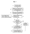
- Fig. 1 shows a diagram describing a method for attaching a lens holder to an uncut lens for a spectacle lens as an embodiment of the present invention.
- the present embodiment of the method for attaching a lens holder to an uncut lens for a spectacle lens comprises steps S1 to S8. These steps essentially accompany movement of an uncut lens, decision of the position of the uncut lens and measurement of the position of the uncut lens with using a moving stage; measurements, formation of an image and image processing with using a lens meter; and a blocking operation with using a blocking apparatus. Therefore, the apparatus for attaching a lens holder to a spectacle lens constituted with these apparatuses and a computer will be described first and the method for attaching a lens holder to an uncut lens for a spectacle lens will be described thereafter.
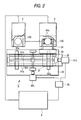
- a blocking apparatus 2 a moving stage 3 and a lens meter 4 are connected to a computer 6 in a manner such that information can be exchanged with a computer 6 and necessary control and information processing can be made by the computer 6.
- an uncut lens 100 is held by suction to sucking apparatuses 34a for holding a lens disposed in a lens holding portion 34 of the moving stage 3 and the uncut lens 100 is moved in a manner such that a specific position in the uncut 100 lens is brought exactly to the position for the measurement in the lens meter 4 or the position for the attachment in the blocking apparatus 2 and is fixed at the selected position.
- the information on the positions is sent to the computer 6.
- the measurements using the lens meter 4 and the movement to the blocking apparatus are conducted while the uncut lens 100 is held by suction at the suction apparatus 34 so that quick movements can be achieved.
- the operation is conducted as described above.
- the uncut lens may be fixed to a placing table disposed on the lens meter 4 and then temporarily released from the holding by suction. After the measurement, the uncut lens may be held by suction again and moved.
- the lens meter 4 optical properties such as the spherical dioptric power, the cylindrical dioptric power, the degree of cylinder axis and the prism value of the uncut lens 100 such as a multifocal lens (HR) and a bifocal lens (HN) are measured, an image of the uncut lens 100 is formed and the positions of hidden marks or the position of the edge of the segment is derived by processing the formed image.
- the position for attaching the lens holder (the blocking position) is derived by a prescribed processing of the data of the positions, the data of the shape of the spectacle frame for the lens obtained in advance, the data of prescription (the data of the layout) and the data of the shape of the lens holder.
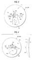
- the progressive multifocal lens (HR) 140 and the bifocal lens (the multifocal lens; HN) 150 will be described with reference to Figs. 3 and 4 in the following.
- the progressive multifocal lens HR 140 has marks 103A and 103B, which are so-called hidden marks, exhibited at two positions separated from a geometric center O by the same distance (for example, 17 mm) on a horizontal reference line 102 which passes the geometric center O.
- the lens is designed in a manner such that the geometric center O, the optical center of the portion for measuring the distance dioptric power 105, the optical center of the portion for measuring the near dioptric power 106 and the position of the eyepoint 107 are obtained from the positions of the hidden marks 103A and 103B. Therefore, the portion for measuring the distance dioptric power 105 is derived from the positions of the hidden marks 103A and 103B and the dioptric power (the distance dioptric power) is measured.
- the hidden marks 103A and 103B are shown by the same small circles or by a small circle and a character. Below the hidden mark, a number exhibiting the additional dioptric power 108 of the lens HR (the difference between the outer vertex power of the distance portion and the outer vertex power of the near portion) and an identification mark 109 exhibiting the type of the lens (for example, G1) are shown.
- the number exhibiting the additional dioptric power 108 is expressed by a number of three digits (for example, 300) below the hidden mark at the side of the ear when the spectacle glass is worn. Therefore, it can be found whether a spectacle lens is used for the left eye or the right eye from the knowledge that the number of three digits is placed below the hidden mark at the left side or the right side, respectively.
- the spectacle lens shown in Fig. 3 is used for the right eye.
- the hidden mark at the left side 103A is exhibited as a small circle "o" and the hidden mark at the right side 103B is exhibited as an alphabet "H”.
- the hidden marks 103A and 103B, the number exhibiting the additional dioptric power 108 and the identification mark 109 are formed on the convex surface of the lens HR as minute protrusions (about 2 to 4 ⁇ m) when the lens is produced by molding.
- the portion for measuring the distance dioptric power 105, the portion for measuring the near dioptric power 106 and the eyepoint 107 should be placed at reference positions separated from the geometric center O by specific distances although the reference positions may be different depending on the design of the lens HR.
- the eyepoint 7 is placed at the position separated from the geometric center O by a specific distance d1 (for example, 2 mm) in the upward direction and the distance optical center 110 is placed at the position separated from the position of the eyepoint 107 by a specific distance d2 (for example, 4 mm) in the upward direction.
- the positions of the geometric center O, the eyepoint 107 and the distance of the optical center 110 can be derived by forming images of hidden marks 103A and 103B and calculating the coordinates of the positions by processing the formed images.
- the portion 111 is a portion for seeing distant things (a distance portion)
- the portion 112 is a portion for seeing near things (a near portion)
- the potion 113 is a portion in which the dioptric power continuously changes (a progressive portion).
- the multifocal lens 150 has a main lens 151 and a segment 152 and is designed in a manner such that the positions of the geometric center O, the optical center of the portion for measuring the near dioptric powder 118 and the eyepoint 119 can be derived using the upper edge of the segment 152 as the reference mark (the edge of the segment). Therefore, the dioptric power (the distance dioptric power) is measured after finding the position of the eyepoint 119 from the position of the upper edge 117 of the segment 152.
- the segment 152 is formed in a shape protruded from the surface of the main lens 151 in a manner such that the side view shows a shape of a wedge.
- the upper edge 117 of the segment 152 is formed at a position separated from a horizontal reference line 102 which passes the geometric center O by a specific distance d3 (for example, 5 mm) in the downward direction.
- d3 for example, 5 mm
- the segment 152 is formed in a manner such that the optical center 118 of the portion for measuring the near dioptric power is separated from the geometric center O by a specific distance d4 (for example, 5 mm) in the rightward direction.
- the eyepoint 119 is fixed at a position separated from the geometric center O by a specific distance (for example, 2.5 mm) on the horizontal reference line 102 to the side of the segment 152. Therefore, the positions of the geometric center O and the eyepoint 119 can be derived by forming an image of the segment 152, setting the upper edge 117 as the edge of the segment which is the boundary of the main lens and the segment and calculating the coordinates of the position of the center of the edge of segment by the image processing.
- the upper edge 117 of the segment 152 in this case corresponds to the hidden marks 103A and 103B in the case of the progressive multifocal lens HR described above.
- the portion 120 is a portion for measuring the distance dioptric power.
- Fig. 4 shows a spectacle lens used for the right eye.
- the lens meter 4 comprises an apparatus for forming and processing an image 440 which is used for detecting the marks and calculating the position of the eyepoint, an apparatus for measuring the distance dioptic power 441 and an apparatus for measuring the height 442 which is used for measuring the height of the concave surface.
- the apparatus for forming and processing an image 440 comprises a light source 450 for a progressive multifocal lens disposed above a position for detecting marks E1 and a condenser lens 451, a diaphragm 452 and a half-mirror 453 disposed in the light path between the light source 450 and the lens HR or the lens HN.
- the light source 450 is used for detecting marks of the progressive multifocal lens HR shown in Fig. 3.
- an LED emitting red light having a narrow width of the wavelength is used so that sharp images of the hidden marks 103A and 103B, the number exhibiting the additional dioptric power 108 and the identification mark 109 can be derived.
- the half-mirror 453 a mirror having the ratio of the transmitted light and the reflected light of 7 to 3 is used.
- the apparatus for forming and processing an image 440 comprises a switching means 454, an image input device 458 such as CCD, an image forming device 459 and a lens for focus adjustment 460 which are disposed at the side of the convex surface of the lens HR or the lens HN and convergent lenses 461 and 462 fixed at a supporting cylinder 472, an image formation lens 463. a reflecting screen 464 and light sources 465.
- the switching means 454 comprises a shutter 455 and a driving apparatus 456 such as an air cylinder for selectively inserting the shutter 455 into the light path between the half-mirror 453 and the apparatus for holding a lens 443 and is constructed to keep the shutter 455 outside the light path during detection of the marks and insert the shutter 455 into the light path during the measurement of the dioptric power of the lens.
- This means is used so that outside light from the apparatus for forming and processing an image 440 does not enter into the image input device 458 through the half-mirror 453 during the measurement of the dioptric power.
- the lens for focus adjustment 460 is kept outside the light path during the detection of marks on the lens HR. During the detection of the position of the edge of the segment (the upper edge 117 of the segment 152) as the mark of the lens HN, the lens for focus adjustment 460 is inserted into the light path between the half-mirror 453 and the image input device 458 and used for focussing the image input device 458 on the convex surface a of the lens HN.
- the image formation lens 463 comprises convex lenses.
- the rays of the image of the convex surface of the lens HR or the lens HN converge through the convergent lenses 461 and 462 and form an image of the convex surface of the lens HR or the lens HN having about the same size on the reflecting screen 464 through the image formation lens 463.
- the image formation lens 463 is used as a light transfer lens when the spectacle lens is a multifocal lens HN.
- a reflecting sheet having a substrate coated with fine power such as fine powder of glass and aluminum as particles for increasing the reflectivity and enhancing scattering of light is laminated on the reflecting screen 464.
- the screen is rotated at a high speed (for example, 3,400 rpm) by a motor 476 to make the lightness of the surface and the background uniform and the image of the convex surface of the lens HR or the lens HN is reflected.
- the contrast between the portion of the hidden marks and portions other than the hidden marks is enhanced by this procedure.
- the rays of the image of the convex surface of the lens HR or the lens HN formed on the reflecting screen 464 are transferred back to the convex surface a of the lens HR or the lens HN, respectively, via the same paths as those of the rays of the incident light, are reflected by the half-mirror 453 and form an image on the light receiving surface of the image input device 458.
- the image thus input is taken into the image forming device 459 and subjected to the image processing.
- the light sources 465 are used for forming the image of the multifocal lens HN shown in Fig. 4.
- LED of red light is used as the light source.
- a plurality of LED, for example, eight LED's, are disposed at the same distance between each other in the circumferential direction along an outer circumference below the image formation lens 463.
- the rays emitted from the light sources 465 are reflected by the reflecting screen 464, pass through the image formation lens 463 and the convergent lenses 462 and 461 and then irradiate the concave surface b of the multifocal lens HN.
- the rays of the image of the convex surface of the lens HN are reflected at the half mirror 453, pass the lens for focus adjustment 460 and form an image on the image input device 458.
- the multifocal lens HN is irradiated with the rays from the light sources 465 on the concave surface b since the shadow of the upper edge 117 of the segment 152, i.e., the edge of the segment, is more clearly projected in comparison with the case in which the multifocal lens HN is irradiated on the convex surface a .
- the light source 450 for a progressive multifocal lens is lighted and the mark is detected while the switching means 454 and the lens for focus adjustment 460 are kept outside the light path of the apparatus for forming and processing an image 440.
- the light sources 465 are extinguished at this time.
- the rays from the light source 450 irradiate the lens HR and the rays of the image of the convex surface exhibiting the hidden marks 103A and 103B, the number exhibiting the additional dioptric power 108 and the identification mark 109 converge through the convergent lenses 461 and 462 and form an image of the convex surface of the lens HR on the reflecting screen 464 through the image formation lens 463.
- the rays of the image of the convex surface of the lens HR formed on the reflecting screen 464 are reflected back to the convex surface a of the lens HR via the same paths as those of the rays of the incident light, are reflected by the half-mirror 453 and form an image on the light receiving surface of the image input device 458.
- the formed image is input into the image forming device 459 and subjected to the image processing.
- the hidden marks 103A and 103B, the number exhibiting the additional dioptric power 108 and the identification mark 109 are detected and the positions of the hidden marks 103A and 103B are calculated.
- the positions of the geometric center O and the eyepoint 107 are obtained by calculation based on the information of the positions of the hidden marks 103A and 103B. Based on the information on the lens, the data on the shape of the spectacle frame and the data of the prescription of the person who is to wear the spectacle glasses, the center of processing and the angle of attachment of the axis line of the lens holder 20 with respect to the lens HR, which will be described later, are decided.
- the light sources for the multifocal lens 465 are used in place of the light source for the progressive multifocal lens 450.
- the lens for focus adjustment 460 is inserted into the light path between the half mirror 453 and the image input device 458 and the image input device 458 is focussed on the convex surface a of the lens HN.
- the light sources 465 are lighted, the rays irradiate the reflecting screen 464 and are reflected.
- the reflected rays pass through the image formation lens 463 and projection lenses 462 and 461 and irradiate the lens HN at the concave surface b .
- the rays of the image of the upper edge 117 of the segment 152 formed on the convex surface a are reflected by the half mirror 453 and brought to the image input device 458.
- the image input into the image input device 458 is transferred to the image forming device 459 and subjected to the image processing.
- the upper edge 117 is detected and the position of the upper edge 117 is calculated.
- the positions of the geometric center O and of the eyepoint 119 are calculated (Fig. 4). Based on the obtained information of the lens, the data of the shape of the spectacle frame and the data of the prescription of the person who is to wear the spectacle glasses, the center of processing and the angle of attachment of the axis line of the lens holder 20 with respect to the lens HN are decided.
- the light source for the progressive multifocal lens 450 and the image input device 458 are disposed at the side of the convex surface a of lens HR or the lens HN and the image of the convex surface of the lens HR is formed, strain of the image due to the cylinder axis is not formed even if the lens HR has a cylindrical dioptric power, and an excellent image can be obtained by projecting the image of the convex surface of the lens HR on the reflecting screen 464 disposed at the side of the concave surface b and bringing the image reflected by the reflecting screen 464 back to the side of the convex surface a of the lens HR and then to the image input device 458.
- the strained image returns to the side of the convex surface a through the lens HR after the image is reflected by the reflecting screen 464, the image is strained again by the cylinder axis.
- the strain in the image formed in the path to the reflecting screen 464 is cancelled due to the strain formed in the path after being reflected. Therefore, an unstrained image is formed on the light receiving surface of the image input device 458 and the image processing can be conducted by the image forming device 459 easily without complicated corrections.
- the lens is a multifocal lens HN.
- the light irradiates the spectacle lens at the concave surface and the image of the upper edge 117 of the segment 152 on the convex surface is directly formed in the image input device 458.
- the formed image does not have the strain due to the cylinder axis and an excellent image can be obtained. Therefore, the image processing can also be conducted easily in this case.
- the uncut lens 100 is transferred to a position for measuring the height and the dioptric power E2 while the uncut lens is held by the sucking apparatuses 34a and the height of the concave surface b and the distance dioptric power of the lens HR or the lens HN are measured.
- an apparatus for measuring the height of the concave surface b of the lens HR or the lens HN 442 is disposed at the position for measuring the height and the dioptric power E2.
- the apparatus for measuring the height 442 comprises the light source 500 which is disposed below the position for measuring the height and the dioptric power E2 and irradiates the lens HR or the lens HN at the concave surface b , a light transfer lens 501 which arranges the rays 483 irradiated from the light source 500 into parallel rays, a collimator lens 490 which forms the image of the light source on the concave surface b of the lens HN and a target 502 which is disposed between the collimator lens 490 and the light transfer lens 501 and can be moved freely in the direction of the optical axis.
- Three mirrors 503a, 503b and 503c, an object lens 504 and a transmitting screen 505 are disposed at the side of the convex surface a of the lens HR or the lens HN.
- the lens for the examination is the progressive multifocal lens NR or the multifocal lens HN described above, the distance dioptric power of the lens is measured.
- the range of measurement of the dioptric power of a lens by the apparatus for measuring the distance dioptic power 441 is, for example, -20D to +15D.
- the light source 500 is composed of four light emitting diodes (LED) 500a to 500d of a high luminance.
- the light emitting diodes are arranged at apices of a square whose center is at the optical axis so that the calculation is facilitated.
- a pinhole plate having a pinhole 510 having a diameter of about 1 mm at the center is used as the target 502.
- the image of the pinhole 510 is formed on the transmitting screen 505 as a pattern image of the target 502 by the action of the collimator lens 490 and the object lens 504.
- the object lens 504 is disposed between the mirror 503a and the mirror 503b.
- the transmitting screen 505 is composed of a plate of a synthetic resin having a milk white color or a ground glass and disposed in a manner such that the transmitting screen 505 and the image input device 458 of the apparatus for forming and processing an image 440 face each other through the half mirror 453 placed between them.
- the lens for focus adjustment 460 is removed to the outside of the light path and the switching means 454 is inserted into the light path.
- the light sources 450 and 465 are switched off.
- the light source 500 is lighted (switched on) while the lens for the examination is not placed at the position for measuring the height and the dioptric power E2.
- the emitted rays 483 are arranged into parallel rays by the light transfer lens 501, irradiate the pinhole plate 502 and reach the collimator lens 490.
- the rays After passing the collimator 490, the rays converge at the position of the concave surface b of the lens HR or the lens HN and form an image of the light source. Then, the rays become divergent again, pass the object lens 504 and irradiate the transmitting screen 505.
- the rays of the image of the pinhole 510 of the pinhole plate 502 are arranged into parallel rays by the collimator lens 490 and the image of the pinhole 510 is formed on the transmitting screen 505 by the action of the object lens 504.
- the light 483 passes through the light transfer lens 501, the pinhole 510 of the pinhole plate 502, the collimator lens 490, the mirror 503a, the object lens 504, the mirror 503b and the mirror 503c, successively, and the image of the pinhole is formed on the transmitting screen 505.
- the pinhole plate 502 is kept at the reference position so that the images of the pinhole formed by lighting LED's 500a to 500d each successively are kept approximately at the same position.
- the rays of the image of the pinhole projected on the transmitting screen 505 pass through the transmitting screen 505 and the half mirror 453 and are input as an image into the image input device 458.
- the position of the image of the pinhole is calculated and memorized as the reference position.
- the lens meter has a mechanism for moving the pinhole plate 502 in the direction of the optical axis and adjusting the position of the pinhole plate so that the images are formed at approximately the same position, similarly to conventional lens meters.
- the lens for examination is placed on the apparatus for measuring the height 442.
- the Z stage ( Figure 2) is driven under control and the portion for measuring the distance dioptric power on the concave surface b of the lens for examination is brought to the specific reference height of the measurement.
- the reference height of the measurement is the position of the focus of the collimator lens 490.
- the position of the image of the pinhole formed by the light of each LED and projected on the transmitting screen 505 shifts from the reference position described above due to the prism effect which depends on the dioptric power of the lens for examination.
- the image of the pin hole is input into the image input device 458 and the obtained image is subjected to the image processing by the image forming device 459.
- the amount of the shift of the image of the pinhole is calculated with respect to each of LED's 500a to 500d. In other words, the image of the pinhole is formed at about the same position on the transmitting screen 5050 by moving and adjusting the position of the pinhole plate 502.
- the amount of the movement of the pinhole plate 502 is memorized by the image forming device 459 and the dioptric power of the lens HR or the lens HN is calculated by converting the amount of shift of the image of the pinhole and the amount of movement of the pinhole plate into the dioptric power.
- the basic method of calculation of the dioptric power is described in detail in Japanese Patent Application Laid-Open No. Heisei 2(1990)-216428 applied by the applicant of the present invention.
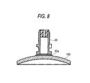
- the blocking apparatus 2 is a conventional apparatus which supports a lens holder 20 and pushes the lens holder 20 to the surface of the uncut lens 100 via an elastic seal 20a to attach the lens holder there.
- the uncut lens 100 is held by a portion for holding a lens 33 of the moving stage 3 and placed on a table for placing a lens 21 at a position fixed in a manner such that the central axis of the lens holder 20 is placed exactly at the position for attachment on the uncut lens 100. Then, the lens holder 20 is attached to the uncut lens.
- the moving stage 3 holds the uncut lens 100 by suction using sucking apparatuses 34a for holding a lens which are disposed at the portion for holding a lens 34 and controls the position by moving the uncut lens and bringing specific positions on the uncut lens 100 exactly at the position of measurement of the lens meter 4 or the position of attachment of the blocking apparatus 2.
- the X-Y table also has the function of transmitting information on the positions to the computer 6.
- the portion for holding a lens 34 is attached to a Z stage 33.
- the Z stage 33 is constructed in a manner such that the Z stage can be moved in the vertical direction (in the direction of the Z axis) together with the portion for holding a lens 34 held by the Z stage 33 by a conventional mechanism for vertical movement (not shown in Figs. 7 and 8).
- the Z stage 33 is attached to an X stage 31.
- the X stage 31 is disposed on a Y stage 32 in a manner such that the X stage can move freely in the X-direction on two rails 31a disposed on the Y stage 32.
- the movement of the X stage is controlled by rotating a screw shaft 31b by a driving pulse motor 31c.
- the screw shaft 31b is screwed into the X stage 31 and attached to the Y stage 32 in a manner such that the screw shaft 31b can freely rotate.
- the Y stage 32 is disposed on a base table 30 in a manner such that the Y stage can freely move in the Y-direction on two rails 32a disposed on the base table 30.
- the movement of the Y stage is controlled by rotating a screw shaft 32b by a driving pulse motor 32c.
- the screw shaft 32b is screwed into the Y stage 32 and attached to the base table 30 in a manner such that the screw shaft 32b can freely rotate.
- the X motor 31c and the Y motor 32c are connected to the computer 6 via a controller 35.
- the computer 6 controls the lens meter 4, the blocking apparatus 2 and the moving stage 3 by transmitting necessary control signals, processes information such as data of image processing and data of positions transmitted from these apparatuses, data of the shape of the spectacle frame which are obtained by an apparatus for measuring the shape of the spectacle frame (not shown in Figs. 7 and 8) or provided as input data, data of the shape of the lens holder, data of the prescription (layout) and the like other information, decides the position for attaching the lens holder and further provides necessary controls to the above apparatuses based on the results.
- the computer controls the apparatuses so that the following steps S1 to S8 are performed as shown in Fig. 1.
- An uncut lens 100 supplied from an apparatus for supplying an uncut lens (not shown in Fig. 1) is held by the sucking apparatuses 34a of the portion for holding a lens 34 of the moving stage 3 (step S1).
- the lens is moved to the portion for the measurement of the lens meter 4 and fixed at a position decided in a manner such that the reference position of the lens meter 4 is brought at an initial position of the uncut lens 100 (step S2).
- a position approximately at the center of the uncut lens (the round lens) is selected since, when the uncut lens transferred by the apparatus for supplying an uncut lens (not shown in Fig. 1) is held by the sucking apparatuses 34a of the portion for holding a lens 34 of the moving stage 3, the above position can be easily indicated and controlled as the position for holding.
- the mode of the measurement by the lens meter is selected in accordance with the type of the uncut lens which is either a progressive multifocal lens (HR) or a multifocal lens (HN) (S3).
- HR progressive multifocal lens
- HN multifocal lens
- An image of the uncut lens is input into the lens meter 4.
- Data of the obtained image is subjected to the image processing and the positions of the hidden marks or the position of the edge of the segment is obtained.
- the information processing is conducted using the data obtained by the above image processing, the data of the shape of the spectacle frame obtained by an apparatus for measuring the shape of the spectacle frame (not shown in Fig. 1) or provided as input data, the data of the shape of the lens holder, the data of the prescription (layout) and the like other information.
- the initial position described above is specified in relation to the optical or geometrical reference position of the shape of the spectacle frame. In this step, the thickness and the dioptric power are measured by means of the lens meter 4.
- the initial position is decided as the blocking position (step S6).
- the blocking position is changed (step S7).
- the uncut lens is moved to the apparatus for blocking and the blocking is conducted (step S8).
- the blocking position is changed to a position approximately at the geometrical center or to a desired position where the processing interference does not take place and necessary conditions as the center of processing are satisfied.
- the lens holder can be attached to a position surely without processing interference even if the spectacle frame has a shape having a remarkably small size in the vertical direction.
- Quick operation can be achieved since the formation of the images and the measurement of the dioptric power by means of the lens meter and the operations of blocking by means of the blocking apparatus are conducted while the uncut lens is held by the sucking apparatuses of the moving stage.
- the present invention is characterized in that the lens holder can he attached to the uncut lens at a position set at the outside of the range of processing interference when the positions of the hidden marks or the position of the edge of the segment is derived by forming and processing the image of the uncut lens by the apparatus for image processing, the obtained positions of the hidden marks or the position of the edge of the segment, the data of the spectacle frame obtained in advance and the data of the shape of the lens buildup area of the lens holder are processed and the lens holder is attached to the uncut lens.
- the range of processing interference is one where the processing interference takes place, i.e., a range where a portion of the shape of a lens buildup area of the lens holder is outside the shape of the spectacle frame and the uncut lens cannot be processed.
- the position outside the range of the processing interference is efficiently obtained and the lens holder can be attached to the uncut lens when the lens holder is attached to a progressive multifocal lens or a multifocal lens.
Abstract
Description
- The present invention relates to a method for attaching a lens holder to an uncut lens for a spectacle lens, the lens holder being a jig which is attached to the uncut lens in advance and used as a central axis of rotation of the uncut lens in a process of grinding an edge of the uncut lens, and an apparatus therefor.
- A spectacle glass is prepared by processing an uncut spectacle lens (in general, a so-called round lens having a circular shape) into a shape fitting the shape of a spectacle frame and fitting the cut lens into the spectacle frame. To prepare the spectacle glass, the layout must be conducted. The layout is realized by the steps of deciding the position of the optical center based on the data of the prescription on the eye of the person who wears the spectacle glass (the dioptric power, the cylindrical dioptric power, the distance between the right and left eyes and the like other data) and the data on the shape of the spectacle frame selected by the person who is to wear the spectacle glass. The layout is conducted essentially for bringing the optical center (in the case of a single vision lens) or the eyepoint (in the case of a multifocal lens) of the spectacle lens at the position of the pupil center of the person who is to wear the spectacle glass after it has been prepared.
- In general, when a person wears a spectacle glass having a spectacle frame selected by the person, it is rather seldom that the geometrical center of the shape of the spectacle frame and the pupil center of the person are at the same position. Therefore, when an uncut lens is processed in the processing of the uncut lens into a shape fitting the shape of the spectacle frame simply in a manner such that the geometrical center of the shape formed by the processing (the shape of the spectacle frame) is brought at the position of the optical center of the lens, a problem arises in that the pupil center is not placed at the position of the optical center or the eyepoint of the spectacle lens when the spectacle glass completed by fitting the processed lens into the spectacle frame is worn. It is necessary that the optical center or the eyepoint is moved or displaced from the position of the geometrical center to a position corresponding to the position of the pupil center.
- When the layout has been completed, an uncut lens (a prescribed lens) which satisfies the conditions for the above layout and the prescription for the person who is to wear the spectacle glass and is suitable for the processing is selected and processed. The processing of the uncut lens is conducted by using an apparatus for processing a lens which grinds edge portions of the uncut lens by a grinder or a cutter while the uncut lens is rotated around a specific axis approximately perpendicular to the optical face of the uncut lens. For processing the uncut lens by the apparatus for processing a lens, a lens holder which is a jig used as the rotational center axis of the uncut lens is attached to the uncut lens in advance.
- Heretofore, the lens holder has been attached at the position of the optical center in the case of a single-vision lens. In the case of a progressive multifocal lens or a multifocal lens (in general, a bifocal lens), the lens holder has been attached at the position of the eyepoint of the lens. As the apparatus for attaching the lens holder at the position of the eyepoint, an apparatus described in Japanese Patent Application Laid-Open No. Heisei 11(1999)-216650 is known.
- When the apparatus described in Japanese Patent Application Laid-Open No. Heisei 11(1999)-216650 is used, images of hidden marks are observed by projecting an image of an uncut lens on a screen and the position of the eyepoint is obtained from the positions of the hidden marks. Then. the position of the uncut lens is decided by moving the uncut lens so that the eyepoint is brought at the position of the center of a cross reticle on the screen showing the reference position of the apparatus for attaching a lens holder and the lens holder is attached at the decided position.
- However, it is recently found that, when spectacle frames having some types of the shape are used, the uncut lens cannot be processed in accordance with the method of attaching a lens holder at the optical center. As the preference of the persons who is to wear spectacle glasses diversifies, spectacle frames having shapes having very small sizes in the vertical direction are occasionally used. When a spectacle frame has a vertical size smaller than a specific value and a lens holder is attached to the optical center, the processing interference takes place. In other words, a portion of the outer periphery of the lens holder comes outside the shape of the spectacle frame (the shape to be formed by the processing). Therefore, the processing becomes impossible.
- The present invention has been made under the above circumstances and has an object of providing a method for attaching a lens holder to an uncut lens for a spectacle lens which enable efficiently obtaining the position for attaching a lens holder without the processing interference and an apparatus therefor.
- As a first aspect, the present invention provides a method for attaching a lens holder to an uncut lens for a spectacle lens, the lens holder being a jig which is attached to the uncut lens in advance and used as a central axis of rotation of the uncut lens in a process of grinding an edge of the uncut lens using an apparatus for processing spectacle lenses under numerical control based on processing data including data of a shape of a spectacle frame, wherein
- the uncut lens is a progressive multifocal lens having a progressively changing dioptric power or a multifocal lens having a segment integrally formed on a main lens;
- the progressive multifocal lens has hidden marks placed in advance at specific positions relative to a reference position in a shape of the spectacle lens, the reference position being a position which is decided in advance by a design of a layout based on a prescription and is at least a position of a geometrical center or a position of an optical center;
- the multifocal lens has the segment arranged on the main lens in a manner such that a position of an edge of the segment which is a boundary of the main lens and the segment is placed at a specific position relative to a reference position in a shape of the spectacle lens, the reference position being a position which is decided in advance by a design of a layout based on a prescription and may be a position of a geometrical center or a position of an optical center; and
- the method comprises the steps of:
- forming an image of the uncut lens by an apparatus for image processing and deriving the positions of the hidden marks or the position of the edge of the segment of the uncut lens by processing the formed image; and
- deriving a position outside a range of a processing interference by information processing of data of the positions of the hidden marks or the position of the edge of the segment obtained as above, the data of the shape of the spectacle frame obtained in advance and data of a shape of a lens buildup area of the lens holder with using a computer, deciding the obtained position as a position for attaching the lens holder to the uncut lens and attaching the lens holder at the decided position, the range of a processing interference being a range where the processing interference takes place, i.e., a range where a portion of the shape of a lens buildup area of the lens holder is outside the shape of the spectacle frame and the uncut lens cannot be processed.
-
- As a second aspect, the present invention provides a method for attaching a lens holder to an uncut lens for a spectacle lens, the lens holder being a jig which is attached to the uncut lens in advance and used as a central axis of rotation of the uncut lens in a process of grinding an edge of the uncut lens using an apparatus for processing spectacle lenses under numerical control based on processing data including data of a shape of a spectacle frame, wherein
- the uncut lens is a progressive multifocal lens having a progressively changing dioptric power or a multifocal lens having a segment integrally formed on a main lens;
- the progressive multifocal lens has hidden marks placed at specific positions relative to a reference position in a shape of the spectacle lens, the reference position being a position which is decided in advance by a design of a layout based on a prescription and is at least a position of a geometrical center or a position of an optical center;
- the multifocal lens has the segment arranged on the main lens in a manner such that a position of an edge of the segment which is a boundary of the main lens and the segment is placed at a specific position relative to a reference position in a shape of the spectacle lens, the reference position being a position which is decided in advance by a design of a layout based on a prescription and is at least a position of a geometrical center or a position of an optical center; and
- the method comprises the steps of:
- fixing the uncut lens to a moving stage which holds the uncut lens at a fixed position, moves to a desired position in accordance with a specific control information, measures a position of itself and outputs information on the position;
- forming an image of the uncut lens by an apparatus for image processing having a reference position set at a specific position relative to a reference position of the moving stage and deriving the positions of the hidden marks or the position of the edge of the segment of the uncut lens by processing the formed image;
- deriving a position outside a range of a processing interference by information processing of data of the positions of the hidden marks or the position of the edge of the segment obtained as above, the data of the shape of the spectacle frame obtained in advance and data of a shape of a lens buildup area of the lens holder with using a computer and deciding the derived position as a position for attaching the lens holder in the uncut lens, the range of a processing interference being a range where the processing interference takes place, i.e., a range where a portion of the shape of a lens buildup area of the lens holder is outside the shape of the spectacle frame and the uncut lens cannot be processed; and
- moving the uncut lens to a specific position in an apparatus for attaching a lens holder by the moving stage so that the lens holder can be attached at the position in the uncut lens decided above, wherein the reference position of the moving stage and the position for attaching the lens holder in the uncut lens are set in a specific relation at the specific position in the apparatus for attaching a lens holder, and attaching the lens holder to the uncut lens by the apparatus for attaching a lens holder.
-
- As a third aspect, the present invention provides an apparatus for attaching a lens holder to an uncut lens for a spectacle lens, the lens holder being a jig which is attached to the uncut lens in advance and used as a central axis of rotation of the uncut lens in a process of grinding an edge of the uncut lens with using an apparatus for processing spectacle lenses under numerical control based on processing data including data of a shape of a spectacle frame, wherein
- the uncut lens is a progressive multifocal lens having a progressively changing dioptric power or a multifocal lens having a segment integrally formed on a main lens;
- the progressive multifocal lens has hidden marks placed at specific positions relative to a reference position in a shape of the spectacle lens, the reference position being a position which is decided in advance by a design of a layout based on a prescription and is at least a position of a geometrical center or a position of an optical center;
- the multifocal lens has the segment arranged on the main lens in a manner such that a position of an edge of the segment which is a boundary of the main lens and the segment is placed at a specific position relative to a reference position in a shape of the spectacle lens, the reference position being a position which is decided in advance by a design of a layout based on a prescription and is at least a position of a geometrical center or a position of an optical center; and
- the apparatus comprises
- a computer;
- a moving stage which holds the uncut lens at a fixed position, moves to a desired position in accordance with a specific control information from the computer, measures a position of itself and outputs information on the position to the computer;
- an apparatus for attaching a lens holder in which a reference position of the moving stage and a position for attaching the lens holder in the uncut lens are set in a specific relation; and
- an apparatus for image processing which has a reference position set at a specific position relative to a reference position of the moving stage and which forms an image of the uncut lens and derives the positions of the hidden marksor the position of the edge of the segment of the uncut lens by processing the formed image based on a command information of the computer;
- the computer being formed for:
- deriving a position outside a range of a processing interference by information processing of data of the positions of the hidden marks or the position of the edge of the segment obtained above, the data of the shape of the spectacle frame obtained in advance and data of a shape of a lens buildup area of the lens holder and for deciding the derived position as a position for attaching the lens holder in the uncut lens, the range of a processing interference being a range where the processing interference takes place, i.e., a range where a portion of the shape of a lens buildup area of the lens holder is outside the shape of the spectacle frame and the uncut lens cannot be processed, and
- for moving the uncut lens to a specific position in an apparatus for attaching a lens holder by the moving stage so that the lens holder can be attached at the position in the uncut lens decided as above, the reference position of the moving stage and the position for attaching the lens holder in the uncut lens being set in a specific relation in the apparatus for attaching a lens holder, and attaching the lens holder to the uncut lens by the apparatus for attaching a lens holder.
-
- In accordance with the first aspect of the present invention, it is made possible that the lens holder is surely attached at a position without the processing interference even when the spectacle frame has a shape having a very small dimension in the vertical direction. In accordance with the second and third aspects of the present invention, it is made possible that the lens holder is attached to a position without the processing interference automatically, surely and quickly.
-
- Fig. 1
- shows a diagram describing a method for attaching a lens holder to an uncut lens for a spectacle lens as an embodiment of the present invention;
- Fig. 2
- shows a diagram exhibiting the entire construction of an apparatus for attaching a lens holder to an uncut lens for a spectacle lens as an embodiment of the present invention;
- Fig. 3
- shows a diagram describing a progressive multifocal lens (HR);
- Fig. 4
- shows a diagram describing a multifocal lens (bifocal lens; HN);
- Fig. 5
- shows a diagram describing a lens meter;
- Fig. 6
- shows a partially expanded diagram describing input of an image of an uncut lens using a lens meter;
- Fig. 7
- shows a diagram describing attachment of a lens holder to an uncut lens using a lens blocking apparatus; and
- Fig. 8
- shows a diagram exhibiting a lens holder attached to an uncut lens.
- Fig. 1 shows a diagram describing a method for attaching a lens holder to an uncut lens for a spectacle lens as an embodiment of the present invention.
- As shown in Fig. 1, the present embodiment of the method for attaching a lens holder to an uncut lens for a spectacle lens comprises steps S1 to S8. These steps essentially accompany movement of an uncut lens, decision of the position of the uncut lens and measurement of the position of the uncut lens with using a moving stage; measurements, formation of an image and image processing with using a lens meter; and a blocking operation with using a blocking apparatus. Therefore, the apparatus for attaching a lens holder to a spectacle lens constituted with these apparatuses and a computer will be described first and the method for attaching a lens holder to an uncut lens for a spectacle lens will be described thereafter.
- In Fig. 2, a blocking
apparatus 2, a movingstage 3 and alens meter 4 are connected to acomputer 6 in a manner such that information can be exchanged with acomputer 6 and necessary control and information processing can be made by thecomputer 6. As will be described later specifically, by the command of thecomputer 6, anuncut lens 100 is held by suction to suckingapparatuses 34a for holding a lens disposed in alens holding portion 34 of the movingstage 3 and theuncut lens 100 is moved in a manner such that a specific position in the uncut 100 lens is brought exactly to the position for the measurement in thelens meter 4 or the position for the attachment in theblocking apparatus 2 and is fixed at the selected position. The information on the positions is sent to thecomputer 6. In the embodiment described in the following, the measurements using thelens meter 4 and the movement to the blocking apparatus are conducted while theuncut lens 100 is held by suction at thesuction apparatus 34 so that quick movements can be achieved. However, it is not always necessary that the operation is conducted as described above. For the measurement using thelens meter 4, after the uncut lens is brought to a fixed position by the movingstage 3, the uncut lens may be fixed to a placing table disposed on thelens meter 4 and then temporarily released from the holding by suction. After the measurement, the uncut lens may be held by suction again and moved. - Using the
lens meter 4, optical properties such as the spherical dioptric power, the cylindrical dioptric power, the degree of cylinder axis and the prism value of theuncut lens 100 such as a multifocal lens (HR) and a bifocal lens (HN) are measured, an image of theuncut lens 100 is formed and the positions of hidden marks or the position of the edge of the segment is derived by processing the formed image. Using thecomputer 6, the position for attaching the lens holder (the blocking position) is derived by a prescribed processing of the data of the positions, the data of the shape of the spectacle frame for the lens obtained in advance, the data of prescription (the data of the layout) and the data of the shape of the lens holder. - The progressive multifocal lens (HR) 140 and the bifocal lens (the multifocal lens; HN) 150 will be described with reference to Figs. 3 and 4 in the following. In Fig. 3. the progressive
multifocal lens HR 140 hasmarks horizontal reference line 102 which passes the geometric center O. The lens is designed in a manner such that the geometric center O, the optical center of the portion for measuring the distancedioptric power 105, the optical center of the portion for measuring the neardioptric power 106 and the position of theeyepoint 107 are obtained from the positions of thehidden marks dioptric power 105 is derived from the positions of thehidden marks - The
hidden marks dioptric power 108 of the lens HR (the difference between the outer vertex power of the distance portion and the outer vertex power of the near portion) and anidentification mark 109 exhibiting the type of the lens (for example, G1) are shown. The number exhibiting the additionaldioptric power 108 is expressed by a number of three digits (for example, 300) below the hidden mark at the side of the ear when the spectacle glass is worn. Therefore, it can be found whether a spectacle lens is used for the left eye or the right eye from the knowledge that the number of three digits is placed below the hidden mark at the left side or the right side, respectively. The spectacle lens shown in Fig. 3 is used for the right eye. The hidden mark at theleft side 103A is exhibited as a small circle "o" and the hidden mark at theright side 103B is exhibited as an alphabet "H". Thehidden marks dioptric power 108 and theidentification mark 109 are formed on the convex surface of the lens HR as minute protrusions (about 2 to 4 □ m) when the lens is produced by molding. - It is specified that the portion for measuring the distance
dioptric power 105, the portion for measuring the neardioptric power 106 and theeyepoint 107 should be placed at reference positions separated from the geometric center O by specific distances although the reference positions may be different depending on the design of the lens HR. For example, the eyepoint 7 is placed at the position separated from the geometric center O by a specific distance d1 (for example, 2 mm) in the upward direction and the distanceoptical center 110 is placed at the position separated from the position of theeyepoint 107 by a specific distance d2 (for example, 4 mm) in the upward direction. Therefore, the positions of the geometric center O, theeyepoint 107 and the distance of theoptical center 110 can be derived by forming images ofhidden marks portion 111 is a portion for seeing distant things (a distance portion), theportion 112 is a portion for seeing near things (a near portion) and thepotion 113 is a portion in which the dioptric power continuously changes (a progressive portion). - In Fig. 4, the
multifocal lens 150 has amain lens 151 and asegment 152 and is designed in a manner such that the positions of the geometric center O, the optical center of the portion for measuring the neardioptric powder 118 and theeyepoint 119 can be derived using the upper edge of thesegment 152 as the reference mark (the edge of the segment). Therefore, the dioptric power (the distance dioptric power) is measured after finding the position of the eyepoint 119 from the position of theupper edge 117 of thesegment 152. - When the lens is made of a plastic material, the
segment 152 is formed in a shape protruded from the surface of themain lens 151 in a manner such that the side view shows a shape of a wedge. Theupper edge 117 of thesegment 152 is formed at a position separated from ahorizontal reference line 102 which passes the geometric center O by a specific distance d3 (for example, 5 mm) in the downward direction. When the spectacle lens is used for the right eye, thesegment 152 is formed in a manner such that theoptical center 118 of the portion for measuring the near dioptric power is separated from the geometric center O by a specific distance d4 (for example, 5 mm) in the rightward direction. Theeyepoint 119 is fixed at a position separated from the geometric center O by a specific distance (for example, 2.5 mm) on thehorizontal reference line 102 to the side of thesegment 152. Therefore, the positions of the geometric center O and theeyepoint 119 can be derived by forming an image of thesegment 152, setting theupper edge 117 as the edge of the segment which is the boundary of the main lens and the segment and calculating the coordinates of the position of the center of the edge of segment by the image processing. Theupper edge 117 of thesegment 152 in this case corresponds to thehidden marks segment 152 is at the left side or the right side of the geometric center, respectively. Theportion 120 is a portion for measuring the distance dioptric power. Fig. 4 shows a spectacle lens used for the right eye. - The construction of the
lens meter 4 will be described with reference to Figure 5. Thelens meter 4 comprises an apparatus for forming and processing animage 440 which is used for detecting the marks and calculating the position of the eyepoint, an apparatus for measuring thedistance dioptic power 441 and an apparatus for measuring theheight 442 which is used for measuring the height of the concave surface. - The apparatus for forming and processing an
image 440 comprises alight source 450 for a progressive multifocal lens disposed above a position for detecting marks E1 and acondenser lens 451, adiaphragm 452 and a half-mirror 453 disposed in the light path between thelight source 450 and the lens HR or the lens HN. Thelight source 450 is used for detecting marks of the progressive multifocal lens HR shown in Fig. 3. For example, an LED emitting red light having a narrow width of the wavelength is used so that sharp images of thehidden marks dioptric power 108 and theidentification mark 109 can be derived. As the half-mirror 453, a mirror having the ratio of the transmitted light and the reflected light of 7 to 3 is used. - The apparatus for forming and processing an
image 440 comprises a switching means 454, animage input device 458 such as CCD, animage forming device 459 and a lens forfocus adjustment 460 which are disposed at the side of the convex surface of the lens HR or the lens HN andconvergent lenses image formation lens 463. a reflectingscreen 464 andlight sources 465. - The switching means 454 comprises a
shutter 455 and adriving apparatus 456 such as an air cylinder for selectively inserting theshutter 455 into the light path between the half-mirror 453 and the apparatus for holding alens 443 and is constructed to keep theshutter 455 outside the light path during detection of the marks and insert theshutter 455 into the light path during the measurement of the dioptric power of the lens. This means is used so that outside light from the apparatus for forming and processing animage 440 does not enter into theimage input device 458 through the half-mirror 453 during the measurement of the dioptric power. - The lens for
focus adjustment 460 is kept outside the light path during the detection of marks on the lens HR. During the detection of the position of the edge of the segment (theupper edge 117 of the segment 152) as the mark of the lens HN, the lens forfocus adjustment 460 is inserted into the light path between the half-mirror 453 and theimage input device 458 and used for focussing theimage input device 458 on the convex surface a of the lens HN. - In Fig. 5, the
image formation lens 463 comprises convex lenses. The rays of the image of the convex surface of the lens HR or the lens HN converge through theconvergent lenses screen 464 through theimage formation lens 463. Theimage formation lens 463 is used as a light transfer lens when the spectacle lens is a multifocal lens HN. - On the reflecting
screen 464, a reflecting sheet having a substrate coated with fine power such as fine powder of glass and aluminum as particles for increasing the reflectivity and enhancing scattering of light is laminated. The screen is rotated at a high speed (for example, 3,400 rpm) by amotor 476 to make the lightness of the surface and the background uniform and the image of the convex surface of the lens HR or the lens HN is reflected. The contrast between the portion of the hidden marks and portions other than the hidden marks is enhanced by this procedure. The rays of the image of the convex surface of the lens HR or the lens HN formed on the reflectingscreen 464 are transferred back to the convex surface a of the lens HR or the lens HN, respectively, via the same paths as those of the rays of the incident light, are reflected by the half-mirror 453 and form an image on the light receiving surface of theimage input device 458. The image thus input is taken into theimage forming device 459 and subjected to the image processing. - The
light sources 465 are used for forming the image of the multifocal lens HN shown in Fig. 4. LED of red light is used as the light source. A plurality of LED, for example, eight LED's, are disposed at the same distance between each other in the circumferential direction along an outer circumference below theimage formation lens 463. The rays emitted from thelight sources 465 are reflected by the reflectingscreen 464, pass through theimage formation lens 463 and theconvergent lenses half mirror 453, pass the lens forfocus adjustment 460 and form an image on theimage input device 458. The multifocal lens HN is irradiated with the rays from thelight sources 465 on the concave surface b since the shadow of theupper edge 117 of thesegment 152, i.e., the edge of the segment, is more clearly projected in comparison with the case in which the multifocal lens HN is irradiated on the convex surface a. - When, with the detection of the marks on the lens, the lens fixed by suction at the sucking
apparatuses 34a turnes out to be a progressive multifocal lens HR, thelight source 450 for a progressive multifocal lens is lighted and the mark is detected while the switching means 454 and the lens forfocus adjustment 460 are kept outside the light path of the apparatus for forming and processing animage 440. Thelight sources 465 are extinguished at this time. - When the
light source 450 is lighted, the rays from thelight source 450 irradiate the lens HR and the rays of the image of the convex surface exhibiting thehidden marks dioptric power 108 and theidentification mark 109 converge through theconvergent lenses screen 464 through theimage formation lens 463. The rays of the image of the convex surface of the lens HR formed on the reflectingscreen 464 are reflected back to the convex surface a of the lens HR via the same paths as those of the rays of the incident light, are reflected by the half-mirror 453 and form an image on the light receiving surface of theimage input device 458. The formed image is input into theimage forming device 459 and subjected to the image processing. Thehidden marks dioptric power 108 and theidentification mark 109 are detected and the positions of thehidden marks - It is found whether the lens is used for the right eye or the left eye from the position of the number exhibiting the additional
dioptric power 108 and the type of the lens is detected from theidentification mark 109. The positions of the geometric center O and the eyepoint 107 (Fig. 3) are obtained by calculation based on the information of the positions of thehidden marks lens holder 20 with respect to the lens HR, which will be described later, are decided. - When the lens is the multifocal lens HN, the light sources for the
multifocal lens 465 are used in place of the light source for the progressivemultifocal lens 450. The lens forfocus adjustment 460 is inserted into the light path between thehalf mirror 453 and theimage input device 458 and theimage input device 458 is focussed on the convex surface a of the lens HN. When thelight sources 465 are lighted, the rays irradiate the reflectingscreen 464 and are reflected. The reflected rays pass through theimage formation lens 463 andprojection lenses upper edge 117 of thesegment 152 formed on the convex surface a are reflected by thehalf mirror 453 and brought to theimage input device 458. The image input into theimage input device 458 is transferred to theimage forming device 459 and subjected to the image processing. Theupper edge 117 is detected and the position of theupper edge 117 is calculated. - Based on the information of the position of the
upper edge 117, the positions of the geometric center O and of theeyepoint 119 are calculated (Fig. 4). Based on the obtained information of the lens, the data of the shape of the spectacle frame and the data of the prescription of the person who is to wear the spectacle glasses, the center of processing and the angle of attachment of the axis line of thelens holder 20 with respect to the lens HN are decided. - As described above, when the light source for the progressive
multifocal lens 450 and theimage input device 458 are disposed at the side of the convex surface a of lens HR or the lens HN and the image of the convex surface of the lens HR is formed, strain of the image due to the cylinder axis is not formed even if the lens HR has a cylindrical dioptric power, and an excellent image can be obtained by projecting the image of the convex surface of the lens HR on the reflectingscreen 464 disposed at the side of the concave surface b and bringing the image reflected by the reflectingscreen 464 back to the side of the convex surface a of the lens HR and then to theimage input device 458. In other words, when the rays irradiate the convex surface a, strains are formed in the image of the surface of the convex surface with passing the lens HR due to the cylinder axis and the strained image is projected to the reflectingscreen 464. - However, since the strained image returns to the side of the convex surface a through the lens HR after the image is reflected by the reflecting
screen 464, the image is strained again by the cylinder axis. The strain in the image formed in the path to the reflectingscreen 464 is cancelled due to the strain formed in the path after being reflected. Therefore, an unstrained image is formed on the light receiving surface of theimage input device 458 and the image processing can be conducted by theimage forming device 459 easily without complicated corrections. - When the lens is a multifocal lens HN. the light irradiates the spectacle lens at the concave surface and the image of the
upper edge 117 of thesegment 152 on the convex surface is directly formed in theimage input device 458. The formed image does not have the strain due to the cylinder axis and an excellent image can be obtained. Therefore, the image processing can also be conducted easily in this case. - When the detection of the marks on the lens HR or the lens HN of the
uncut lens 100 is completed, theuncut lens 100 is transferred to a position for measuring the height and the dioptric power E2 while the uncut lens is held by the suckingapparatuses 34a and the height of the concave surface b and the distance dioptric power of the lens HR or the lens HN are measured. - In Fig. 5, an apparatus for measuring the height of the concave surface b of the lens HR or the
lens HN 442 is disposed at the position for measuring the height and the dioptric power E2. The apparatus for measuring theheight 442 comprises thelight source 500 which is disposed below the position for measuring the height and the dioptric power E2 and irradiates the lens HR or the lens HN at the concave surface b, alight transfer lens 501 which arranges therays 483 irradiated from thelight source 500 into parallel rays, acollimator lens 490 which forms the image of the light source on the concave surface b of the lens HN and atarget 502 which is disposed between thecollimator lens 490 and thelight transfer lens 501 and can be moved freely in the direction of the optical axis. - Three
mirrors object lens 504 and atransmitting screen 505 are disposed at the side of the convex surface a of the lens HR or the lens HN. In the present embodiment, since the lens for the examination is the progressive multifocal lens NR or the multifocal lens HN described above, the distance dioptric power of the lens is measured. The range of measurement of the dioptric power of a lens by the apparatus for measuring thedistance dioptic power 441 is, for example, -20D to +15D. - The
light source 500 is composed of four light emitting diodes (LED) 500a to 500d of a high luminance. The light emitting diodes are arranged at apices of a square whose center is at the optical axis so that the calculation is facilitated. As thetarget 502, a pinhole plate having apinhole 510 having a diameter of about 1 mm at the center is used. The image of thepinhole 510 is formed on thetransmitting screen 505 as a pattern image of thetarget 502 by the action of thecollimator lens 490 and theobject lens 504. - The
object lens 504 is disposed between themirror 503a and themirror 503b. Thetransmitting screen 505 is composed of a plate of a synthetic resin having a milk white color or a ground glass and disposed in a manner such that thetransmitting screen 505 and theimage input device 458 of the apparatus for forming and processing animage 440 face each other through thehalf mirror 453 placed between them. - When the distance dioptric power of the lens HR or the lens HN is measured, the lens for
focus adjustment 460 is removed to the outside of the light path and the switching means 454 is inserted into the light path. Thelight sources light source 500 is lighted (switched on) while the lens for the examination is not placed at the position for measuring the height and the dioptric power E2. When thelight source 500 is lighted, the emittedrays 483 are arranged into parallel rays by thelight transfer lens 501, irradiate thepinhole plate 502 and reach thecollimator lens 490. After passing thecollimator 490, the rays converge at the position of the concave surface b of the lens HR or the lens HN and form an image of the light source. Then, the rays become divergent again, pass theobject lens 504 and irradiate thetransmitting screen 505. - When the effect of the dioptric power of the spectacle lens is absent (0.00D) in the formation of the image of the
pinhole 510 of thepinhole plate 502 on thetransmitting screen 505, the rays of the image of thepinhole 510 of thepinhole plate 502 are arranged into parallel rays by thecollimator lens 490 and the image of thepinhole 510 is formed on thetransmitting screen 505 by the action of theobject lens 504. In other words, when LED's 500a to 500d are each successively lighted while neither the lens HR nor the lens HN is placed at the apparatus for measuring theheight 442, the light 483 passes through thelight transfer lens 501, thepinhole 510 of thepinhole plate 502, thecollimator lens 490, themirror 503a, theobject lens 504, themirror 503b and themirror 503c, successively, and the image of the pinhole is formed on thetransmitting screen 505. At this time, thepinhole plate 502 is kept at the reference position so that the images of the pinhole formed by lighting LED's 500a to 500d each successively are kept approximately at the same position. - The rays of the image of the pinhole projected on the
transmitting screen 505 pass through thetransmitting screen 505 and thehalf mirror 453 and are input as an image into theimage input device 458. By forming the image of the pinhole and subjecting the image to the image processing by theimage forming device 459, the position of the image of the pinhole is calculated and memorized as the reference position. When the lens for the examination is placed in the passage of the light, the images of the pinhole of thepinhole plate 502 formed by lighting LED's 500a to 500d each successively are not kept approximately at the same position of thetransmitting screen 505. Therefore, the lens meter has a mechanism for moving thepinhole plate 502 in the direction of the optical axis and adjusting the position of the pinhole plate so that the images are formed at approximately the same position, similarly to conventional lens meters. - When the distance dioptric power of the lens for examination is measured, the lens for examination is placed on the apparatus for measuring the
height 442. Based on the information on the height of the concave surface b obtained by the measurement by the apparatus for measuring theheight 442, the Z stage (Figure 2) is driven under control and the portion for measuring the distance dioptric power on the concave surface b of the lens for examination is brought to the specific reference height of the measurement. The reference height of the measurement is the position of the focus of thecollimator lens 490. When the portion for the measuring the distance dioptric power on the concave surface b of the lens for examination is brought to the specific reference height of the measurement, the measurement of the dioptric power (the distance dioptric power) is conducted under this condition. The measurement of the dioptric power is conducted while LED's 500a to 500d are lighted each successively. - Since the light 483 from LED's 500a to 500d passes through the lens for examination, the position of the image of the pinhole formed by the light of each LED and projected on the
transmitting screen 505 shifts from the reference position described above due to the prism effect which depends on the dioptric power of the lens for examination. The image of the pin hole is input into theimage input device 458 and the obtained image is subjected to the image processing by theimage forming device 459. The amount of the shift of the image of the pinhole is calculated with respect to each of LED's 500a to 500d. In other words, the image of the pinhole is formed at about the same position on the transmitting screen 5050 by moving and adjusting the position of thepinhole plate 502. The amount of the movement of thepinhole plate 502 is memorized by theimage forming device 459 and the dioptric power of the lens HR or the lens HN is calculated by converting the amount of shift of the image of the pinhole and the amount of movement of the pinhole plate into the dioptric power. The basic method of calculation of the dioptric power is described in detail in Japanese Patent Application Laid-Open No. Heisei 2(1990)-216428 applied by the applicant of the present invention. - The blocking
apparatus 2 will be described in the following. As shown in Figs. 7 and 8, the blockingapparatus 2 is a conventional apparatus which supports alens holder 20 and pushes thelens holder 20 to the surface of theuncut lens 100 via anelastic seal 20a to attach the lens holder there. Theuncut lens 100 is held by a portion for holding alens 33 of the movingstage 3 and placed on a table for placing alens 21 at a position fixed in a manner such that the central axis of thelens holder 20 is placed exactly at the position for attachment on theuncut lens 100. Then, thelens holder 20 is attached to the uncut lens. - By a command from the
computer 6, the movingstage 3 holds theuncut lens 100 by suction using suckingapparatuses 34a for holding a lens which are disposed at the portion for holding alens 34 and controls the position by moving the uncut lens and bringing specific positions on theuncut lens 100 exactly at the position of measurement of thelens meter 4 or the position of attachment of the blockingapparatus 2. The X-Y table also has the function of transmitting information on the positions to thecomputer 6. - The portion for holding a
lens 34 is attached to aZ stage 33. TheZ stage 33 is constructed in a manner such that the Z stage can be moved in the vertical direction (in the direction of the Z axis) together with the portion for holding alens 34 held by theZ stage 33 by a conventional mechanism for vertical movement (not shown in Figs. 7 and 8). TheZ stage 33 is attached to anX stage 31. TheX stage 31 is disposed on aY stage 32 in a manner such that the X stage can move freely in the X-direction on tworails 31a disposed on theY stage 32. The movement of the X stage is controlled by rotating ascrew shaft 31b by a drivingpulse motor 31c. Thescrew shaft 31b is screwed into theX stage 31 and attached to theY stage 32 in a manner such that thescrew shaft 31b can freely rotate. - The
Y stage 32 is disposed on a base table 30 in a manner such that the Y stage can freely move in the Y-direction on tworails 32a disposed on the base table 30. The movement of the Y stage is controlled by rotating ascrew shaft 32b by a drivingpulse motor 32c. Thescrew shaft 32b is screwed into theY stage 32 and attached to the base table 30 in a manner such that thescrew shaft 32b can freely rotate. TheX motor 31c and theY motor 32c are connected to thecomputer 6 via acontroller 35. - The
computer 6 controls thelens meter 4, the blockingapparatus 2 and the movingstage 3 by transmitting necessary control signals, processes information such as data of image processing and data of positions transmitted from these apparatuses, data of the shape of the spectacle frame which are obtained by an apparatus for measuring the shape of the spectacle frame (not shown in Figs. 7 and 8) or provided as input data, data of the shape of the lens holder, data of the prescription (layout) and the like other information, decides the position for attaching the lens holder and further provides necessary controls to the above apparatuses based on the results. Specifically, the computer controls the apparatuses so that the following steps S1 to S8 are performed as shown in Fig. 1. - An
uncut lens 100 supplied from an apparatus for supplying an uncut lens (not shown in Fig. 1) is held by the suckingapparatuses 34a of the portion for holding alens 34 of the moving stage 3 (step S1). The lens is moved to the portion for the measurement of thelens meter 4 and fixed at a position decided in a manner such that the reference position of thelens meter 4 is brought at an initial position of the uncut lens 100 (step S2). As the initial position, a position approximately at the center of the uncut lens (the round lens) is selected since, when the uncut lens transferred by the apparatus for supplying an uncut lens (not shown in Fig. 1) is held by the suckingapparatuses 34a of the portion for holding alens 34 of the movingstage 3, the above position can be easily indicated and controlled as the position for holding. - The mode of the measurement by the lens meter is selected in accordance with the type of the uncut lens which is either a progressive multifocal lens (HR) or a multifocal lens (HN) (S3).
- An image of the uncut lens is input into the
lens meter 4. Data of the obtained image is subjected to the image processing and the positions of the hidden marks or the position of the edge of the segment is obtained. The information processing is conducted using the data obtained by the above image processing, the data of the shape of the spectacle frame obtained by an apparatus for measuring the shape of the spectacle frame (not shown in Fig. 1) or provided as input data, the data of the shape of the lens holder, the data of the prescription (layout) and the like other information. The initial position described above is specified in relation to the optical or geometrical reference position of the shape of the spectacle frame. In this step, the thickness and the dioptric power are measured by means of thelens meter 4. - It is estimated whether the processing interference would take place or not when the lens holder would be blocked to the lens at the initial position. In other words, it is estimated whether the processing interference would take place or not under the assumption that the lens holder would be blocked to the lens at the initial position using the data of the shape of the spectacle frame, the data of the prescription and the data of the shape (the diameter) of the lens holder.
- When it is estimated in
step 5 that the processing interference would not take place, the initial position is decided as the blocking position (step S6). When it is estimated instep 5 that the processing interference would take place, the blocking position is changed (step S7). Then, the uncut lens is moved to the apparatus for blocking and the blocking is conducted (step S8). For changing the blocking position, when the initial position is approximately at the center (the optical center) of the uncut lens (the round lens), the blocking position is changed to a position approximately at the geometrical center or to a desired position where the processing interference does not take place and necessary conditions as the center of processing are satisfied. - In accordance with the above embodiments of the process for attaching a lens holder to an uncut lens for a spectacle lens and the apparatus therefor, the lens holder can be attached to a position surely without processing interference even if the spectacle frame has a shape having a remarkably small size in the vertical direction. Quick operation can be achieved since the formation of the images and the measurement of the dioptric power by means of the lens meter and the operations of blocking by means of the blocking apparatus are conducted while the uncut lens is held by the sucking apparatuses of the moving stage.
- As described above, the present invention is characterized in that the lens holder can he attached to the uncut lens at a position set at the outside of the range of processing interference when the positions of the hidden marks or the position of the edge of the segment is derived by forming and processing the image of the uncut lens by the apparatus for image processing, the obtained positions of the hidden marks or the position of the edge of the segment, the data of the spectacle frame obtained in advance and the data of the shape of the lens buildup area of the lens holder are processed and the lens holder is attached to the uncut lens. The range of processing interference is one where the processing interference takes place, i.e., a range where a portion of the shape of a lens buildup area of the lens holder is outside the shape of the spectacle frame and the uncut lens cannot be processed. Thus, the position outside the range of the processing interference is efficiently obtained and the lens holder can be attached to the uncut lens when the lens holder is attached to a progressive multifocal lens or a multifocal lens.
-
- 2: A blocking apparatus;
- 3: a moving stage;
- 4: a lens meter;
- 6: a computer; and
- 100: an uncut lens.
-
Claims (5)
- A method for attaching a lens holder to an uncut lens for a spectacle lens, the lens holder being a jig which is attached to the uncut lens in advance and used as a central axis of rotation of the uncut lens in a process of grinding an edge of the uncut lens using an apparatus for processing spectacle lenses under numerical control based on processing data including data of a shape of a spectacle frame, whereinthe uncut lens is a progressive multifocal lens having a progressively changing dioptric power or a multifocal lens having a segment integrally formed on a main lens;the progressive multifocal lens has hidden marks placed in advance at specific positions relative to a reference position in a shape of the spectacle lens, the reference position being a position which is decided in advance by a design of a layout based on a prescription and is at least a position of a geometrical center or a position of an optical center;the multifocal lens has the segment arranged on the main lens in a manner such that a position of an edge of the segment which is a boundary of the main lens and the segment is placed at a specific position relative to a reference position in a shape of the spectacle lens, the reference position being a position which is decided in advance by a design of a layout based on a prescription and is at least a position of a geometrical center or a position of an optical center; andthe method comprises the steps of:forming an image of the uncut lens by an apparatus for image processing and deriving the positions of the hidden marks or the position of the edge of the segment of the uncut lens by processing the formed image; andderiving a position outside a range of a processing interference by information processing of data of the positions of the hidden marks or the position of the edge of the segment obtained as above, the data of the shape of the spectacle frame obtained in advance and data of a shape of a lens buildup area of the lens holder using a computer, deciding the derived position as a position for attaching the lens holder to the uncut lens and attaching the lens holder at the decided position, the range of a processing interference being a range where the processing interference takes place, i.e., a range where a portion of the shape of a lens buildup area of the lens holder is outside the shape of the spectacle frame and the uncut lens cannot be processed.
- A method for attaching a lens holder to an uncut lens for a spectacle lens, the lens holder being a jig which is attached to the uncut lens in advance and used as a central axis of rotation of the uncut lens in a process of grinding an edge of the uncut lens with using an apparatus for processing spectacle lenses under numerical control based on processing data including data of a shape of a spectacle frame, whereinthe uncut lens is a progressive multifocal lens having a progressively changing dioptric power or a multifocal lens having a segment integrally formed on a main lens;the progressive multifocal lens has hidden marks placed at specific positions relative to a reference position in a shape of the spectacle lens, the reference position being a position which is decided in advance by a design of a layout based on a prescription and is at least a position of a geometrical center or a position of an optical center;the multifocal lens has the segment arranged on the main lens in a manner such that a position of an edge of the segment which is a boundary of the main lens and the segment is placed at a specific position relative to a reference position in a shape of the spectacle lens, the reference position being a position which is decided in advance by a design of a layout based on a prescription and may be a position of a geometrical center or a position of an optical center; andthe method comprises the steps of:fixing the uncut lens to a moving stage which holds the uncut lens at a fixed position, moves to a desired position in accordance with a specific control information, measures a position of itself and outputs information on the position;forming an image of the uncut lens by an apparatus for image processing having a reference position set at a specific position relative to a reference position of the moving stage and deriving the positions of the hidden marks or the position of the edge of the segment of the uncut lens by processing the formed image;deriving a position outside a range of a processing interference by information processing of data of the positions of the hidden marks or the position of the edge of the segment obtained as above, the data of the shape of the spectacle frame obtained in advance and data of a shape of a lens buildup area of the lens holder with using a computer and deciding the derived position as a position for attaching the lens holder in the uncut lens, the range of a processing interference being a range where the processing interference takes place, i.e., a range where a portion of the shape of a lens buildup area of the lens holder is outside the shape of the spectacle frame and the uncut lens cannot be processed; andmoving the uncut lens to a specific position in an apparatus for attaching a lens holder by the moving stage so that the lens holder can be attached at the position in the uncut lens decided as above, the reference position of the moving stage and the position for attaching the lens holder in the uncut lens being set in a specific relation in the apparatus for attaching a lens holder, and attaching the lens holder to the uncut lens by the apparatus for attaching a lens holder.
- A method for producing a progressive multifocal lens, which includes the method steps of any one of claims 1 or 2.
- A method for producing a multifocal lens, which includes the method steps of any one of claims 1 or 2.
- An apparatus for attaching a lens holder to an uncut lens for a spectacle lens, the lens holder being a jig which is attached to the uncut lens in advance and used as a central axis of rotation of the uncut lens in a process of grinding an edge of the uncut lens using an apparatus for processing spectacle lenses under numerical control based on processing data including data of a shape of a spectacle frame, whereinthe uncut lens is a progressive multifocal lens having a progressively changing dioptric power or a multifocal lens having a segment integrally formed on a main lens;the progressive multifocal lens has hidden marks placed at specific positions relative to a reference position in a shape of the spectacle lens, the reference position being a position which is decided in advance by a design of a layout based on a prescription and is at least a position of a geometrical center or a position of an optical center;the multifocal lens has the segment arranged on the main lens in a manner such that a position of an edge of the segment which is a boundary of the main lens and the segment is placed at a specific position relative to a reference position in a shape of the spectacle lens, the reference position being a position which is decided in advance by a design of a layout based on a prescription and is at least a position of a geometrical center or a position of an optical center; andthe apparatus comprises:a computer;a moving stage which holds the uncut lens at a fixed position, moves to a desired position in accordance with a specific control information from the computer, measures a position of itself and outputs information on the position to the computer;an apparatus for attaching a lens holder in which a reference position of the moving stage and a position for attaching the lens holder in the uncut lens are set in a specific relation; andan apparatus for image processing which has a reference position set at a specific position relative to a reference position of the moving stage and which forms an image of the uncut lens and derives the positions of the hidden marks or the position of the edge of the segment of the uncut lens by processing the formed image based on a command information of the computer;the computer being formed for:deriving a position outside a range of a processing interference by information processing of data of the positions of the hidden marks or the position of the edge of the segment obtained as above, the data of the shape of the spectacle frame obtained in advance and data of a shape of a lens buildup area of the lens holder and for deciding the obtained position as a position for attaching the lens holder in the uncut lens, the range of a processing interference being a range where the processing interference takes place, i.e., a range where a portion of the shape of a lens buildup area of the lens holder is outside the shape of the spectacle frame and the uncut lens cannot be processed, andfor moving the uncut lens to a specific position in an apparatus for attaching a lens holder by the moving stage so that the lens holder can be attached at the position in the uncut lens decided as above, wherein the reference position of the moving stage and the position for attaching the lens holder in the uncut lens are set in a specific relation at the specific position in the apparatus for attaching a lens holder, and attaching the lens holder to the uncut lens by the apparatus for attaching a lens holder.
Applications Claiming Priority (2)
| Application Number | Priority Date | Filing Date | Title |
|---|---|---|---|
| JP2000332680 | 2000-10-31 | ||
| JP2000332680A JP2002139713A (en) | 2000-10-31 | 2000-10-31 | Method and device for mounting lens holders of spectacle lens |
Publications (3)
| Publication Number | Publication Date |
|---|---|
| EP1201360A2 true EP1201360A2 (en) | 2002-05-02 |
| EP1201360A3 EP1201360A3 (en) | 2003-03-19 |
| EP1201360B1 EP1201360B1 (en) | 2008-12-17 |
Family
ID=18808854
Family Applications (1)
| Application Number | Title | Priority Date | Filing Date |
|---|---|---|---|
| EP01124457A Expired - Lifetime EP1201360B1 (en) | 2000-10-31 | 2001-10-11 | A method for attaching a lens holder to a spectacle lens, an apparatus therefor. |
Country Status (7)
| Country | Link |
|---|---|
| US (1) | US6722944B2 (en) |
| EP (1) | EP1201360B1 (en) |
| JP (1) | JP2002139713A (en) |
| KR (1) | KR100478881B1 (en) |
| CN (1) | CN1190684C (en) |
| AT (1) | ATE417701T1 (en) |
| DE (1) | DE60137011D1 (en) |
Cited By (5)
| Publication number | Priority date | Publication date | Assignee | Title |
|---|---|---|---|---|
| WO2007012713A1 (en) * | 2005-07-26 | 2007-02-01 | Essilor International (Compagnie Generale D'optique) | Method for trimming an ophthalmologic lens with reacquisition of an initial centering reference frame |
| EP1862258A2 (en) * | 2006-06-02 | 2007-12-05 | Hoya Corporation | System for verifying the accuracy of lens holder attachment, lens attachment stage, and lens processing system |
| WO2007141402A1 (en) * | 2006-06-08 | 2007-12-13 | Essilor International (Compagnie Generale D'optique) | Device and method of trimming a lens including verification of the adequacy of a lock adapter of said lens with a characteristic of this lens or its desired shape |
| FR2935918A1 (en) * | 2008-09-18 | 2010-03-19 | Briot Int | Blank machining i.e. grinding, method for forming ophthalmic lens in optical eyeglasses, involves transmitting request to find geometric properties from identifier, and machining blank for forming lens by using obtained geometric properties |
| US7715023B2 (en) | 2004-03-31 | 2010-05-11 | Kabushiki Kaisha Topcon | Jig mounting apparatus |
Families Citing this family (11)
| Publication number | Priority date | Publication date | Assignee | Title |
|---|---|---|---|---|
| FR2852264B1 (en) * | 2003-03-14 | 2006-02-03 | Briot Int | ANGULAR SHIFT ESTIMATING METHOD, METHOD OF CALIBRATING OPTALMIC GLASS MILLING MACHINE, AND DEVICE FOR IMPLEMENTING SUCH A CALIBRATION METHOD |
| JP4632826B2 (en) * | 2004-03-31 | 2011-02-16 | 株式会社トプコン | Automatic mounting device for spectacle lenses |
| JP4494844B2 (en) * | 2004-03-31 | 2010-06-30 | 株式会社トプコン | Automatic jig mounting device for spectacle lens and suction jig automatic mounting method for spectacle lens |
| JP4541017B2 (en) * | 2004-03-31 | 2010-09-08 | 株式会社トプコン | Lens suction jig mounting device |
| JP4823065B2 (en) * | 2004-06-30 | 2011-11-24 | Hoya株式会社 | Manufacturing method of spectacle lens |
| FR2878975B1 (en) * | 2004-12-03 | 2007-02-16 | Essilor Int | METHOD AND DEVICE FOR PREPARING THE MOUNTING OF A JOB OF TWO OPHTHALMIC LENSES OF THE SAME PAIR OF EYEWEAR |
| JP4993999B2 (en) * | 2006-10-31 | 2012-08-08 | Hoya株式会社 | Semi-finished lens for progressive-power spectacle lens and progressive-power spectacle lens |
| KR100830668B1 (en) * | 2007-02-15 | 2008-05-19 | (주)에이피텍 | Lens holder affix system of camera module |
| FR2974529B1 (en) * | 2011-04-26 | 2013-06-14 | Essilor Int | DEVICE FOR GLANTAGE OF AN OPHTHALMIC LENS |
| MX2015008530A (en) * | 2012-12-31 | 2015-09-10 | Essilor Int | A method of determining the blocking position of an optical lens. |
| ES2632108B1 (en) * | 2017-03-30 | 2018-06-18 | Merindades Vision S.L. | DESIGN PROCEDURE FOR A PAIR OF OPHTHALTIC LENSES AND DEVICE FOR OPTICAL MEASURES |
Citations (1)
| Publication number | Priority date | Publication date | Assignee | Title |
|---|---|---|---|---|
| EP0933163A1 (en) | 1998-01-30 | 1999-08-04 | Nidek Co., Ltd. | Cup attaching apparatus |
Family Cites Families (16)
| Publication number | Priority date | Publication date | Assignee | Title |
|---|---|---|---|---|
| US4945684A (en) * | 1987-01-12 | 1990-08-07 | Hoya Corporation | Method of and apparatus for processing peripheral edge of lens for spectacles |
| JPH0820334B2 (en) | 1988-03-05 | 1996-03-04 | ホーヤ株式会社 | Automatic lens meter |
| JP2801620B2 (en) | 1988-10-05 | 1998-09-21 | 株式会社トプコン | Lens meter |
| JPH10132707A (en) * | 1996-09-05 | 1998-05-22 | Topcon Corp | Concealed mark observer and lens meter |
| JP3667483B2 (en) * | 1997-02-10 | 2005-07-06 | 株式会社ニデック | Lens grinding machine |
| ES2136541B1 (en) * | 1997-05-06 | 2000-08-01 | Indo Int Sa | DEVICE FOR THE CENTERING AND LOCKING OF AN OPHTHALMIC LENS DISC. |
| US6012965A (en) * | 1997-10-07 | 2000-01-11 | Micro Optics Design Corp. | Manufacturing ophthalmic lenses using lens structure cognition and spatial positioning system |
| JP4068233B2 (en) * | 1998-08-31 | 2008-03-26 | 株式会社ニデック | Cup mounting device |
| JPH11216650A (en) * | 1998-01-30 | 1999-08-10 | Nidek Co Ltd | Centering device |
| DE19804489C2 (en) * | 1998-02-05 | 2000-06-15 | Wernicke & Co Gmbh | Spectacle lens processing machine |
| JP3929595B2 (en) * | 1998-03-31 | 2007-06-13 | 株式会社ニデック | Eyeglass lens processing system |
| JP3730406B2 (en) * | 1998-04-30 | 2006-01-05 | 株式会社ニデック | Eyeglass lens processing equipment |
| JP3730409B2 (en) * | 1998-05-29 | 2006-01-05 | 株式会社ニデック | Eyeglass lens processing equipment |
| JP4068229B2 (en) * | 1998-08-03 | 2008-03-26 | 株式会社ニデック | Eyeglass lens layout device |
| JP3778707B2 (en) * | 1998-09-29 | 2006-05-24 | 株式会社ニデック | Eyeglass lens processing equipment |
| JP3842953B2 (en) * | 2000-04-28 | 2006-11-08 | 株式会社ニデック | Cup mounting device |
-
2000
- 2000-10-31 JP JP2000332680A patent/JP2002139713A/en active Pending
-
2001
- 2001-10-11 DE DE60137011T patent/DE60137011D1/en not_active Expired - Lifetime
- 2001-10-11 EP EP01124457A patent/EP1201360B1/en not_active Expired - Lifetime
- 2001-10-11 AT AT01124457T patent/ATE417701T1/en not_active IP Right Cessation
- 2001-10-26 KR KR10-2001-0066180A patent/KR100478881B1/en not_active IP Right Cessation
- 2001-10-29 US US09/984,319 patent/US6722944B2/en not_active Expired - Lifetime
- 2001-10-31 CN CNB01137702XA patent/CN1190684C/en not_active Expired - Fee Related
Patent Citations (1)
| Publication number | Priority date | Publication date | Assignee | Title |
|---|---|---|---|---|
| EP0933163A1 (en) | 1998-01-30 | 1999-08-04 | Nidek Co., Ltd. | Cup attaching apparatus |
Cited By (9)
| Publication number | Priority date | Publication date | Assignee | Title |
|---|---|---|---|---|
| US7715023B2 (en) | 2004-03-31 | 2010-05-11 | Kabushiki Kaisha Topcon | Jig mounting apparatus |
| WO2007012713A1 (en) * | 2005-07-26 | 2007-02-01 | Essilor International (Compagnie Generale D'optique) | Method for trimming an ophthalmologic lens with reacquisition of an initial centering reference frame |
| FR2889319A1 (en) * | 2005-07-26 | 2007-02-02 | Essilor Int | METHOD OF DISTRACTING AN OPHTHALMIC LENS WITH REACQUISITION OF AN INITIAL CENTERING REFERENTIAL |
| EP1862258A2 (en) * | 2006-06-02 | 2007-12-05 | Hoya Corporation | System for verifying the accuracy of lens holder attachment, lens attachment stage, and lens processing system |
| EP1862258A3 (en) * | 2006-06-02 | 2008-11-05 | Hoya Corporation | System for verifying the accuracy of lens holder attachment, lens attachment stage, and lens processing system |
| US7561260B2 (en) | 2006-06-02 | 2009-07-14 | Hoya Corporation | System for verifying the accuracy of lens holder attachment, lens attachment stage, and lens processing system |
| WO2007141402A1 (en) * | 2006-06-08 | 2007-12-13 | Essilor International (Compagnie Generale D'optique) | Device and method of trimming a lens including verification of the adequacy of a lock adapter of said lens with a characteristic of this lens or its desired shape |
| FR2902033A1 (en) * | 2006-06-08 | 2007-12-14 | Essilor Int | DEVICE AND METHOD FOR DETOURING A LENS COMPRISING THE VERIFICATION OF THE ADEQUACY OF A LOCKING ADAPTER OF SAID LENS WITH A CHARACTERISTIC OF THIS LENS OR ITS WISHED CONTOUR |
| FR2935918A1 (en) * | 2008-09-18 | 2010-03-19 | Briot Int | Blank machining i.e. grinding, method for forming ophthalmic lens in optical eyeglasses, involves transmitting request to find geometric properties from identifier, and machining blank for forming lens by using obtained geometric properties |
Also Published As
| Publication number | Publication date |
|---|---|
| CN1352405A (en) | 2002-06-05 |
| US6722944B2 (en) | 2004-04-20 |
| JP2002139713A (en) | 2002-05-17 |
| EP1201360A3 (en) | 2003-03-19 |
| DE60137011D1 (en) | 2009-01-29 |
| US20020052167A1 (en) | 2002-05-02 |
| EP1201360B1 (en) | 2008-12-17 |
| CN1190684C (en) | 2005-02-23 |
| KR100478881B1 (en) | 2005-03-25 |
| KR20020033533A (en) | 2002-05-07 |
| ATE417701T1 (en) | 2009-01-15 |
Similar Documents
| Publication | Publication Date | Title |
|---|---|---|
| EP1201360B1 (en) | A method for attaching a lens holder to a spectacle lens, an apparatus therefor. | |
| CN100566933C (en) | The manufacture method of lens | |
| US5973772A (en) | Layout judgment apparatus and layout judgment system | |
| KR101503061B1 (en) | A cup attaching apparatus | |
| US7530690B2 (en) | Centering and blocking device for an ophthalmic spectacles lens, an automatic detection method, and associated manual centering methods | |
| US7267436B2 (en) | Manufacturing method of spectacle lens, marking apparatus, marking system and spectacle lens | |
| US6671039B2 (en) | Spectacle lens image sensing processing apparatus and spectacle lens positioning method | |
| US6888626B2 (en) | Device for automatically detecting characteristics of an ophthalmic lens and an automatic device for fitting a centering and drive peg incorporating it | |
| EP3676049B1 (en) | Improved method for controlling the polishing of gemstones | |
| AU6653500A (en) | A method and apparatus for automatic attachment of a finishing block to a lens | |
| KR102235908B1 (en) | Method for acquiring and measuring geometrical data of a demonstration lens adapted to a spectacle frame | |
| JP4963977B2 (en) | Eyeglass lens manufacturing system and mark detection apparatus | |
| WO2015129848A1 (en) | Lens inspection apparatus and method for producing eyeglass lens | |
| CN114556047A (en) | Method and apparatus for determining the contour of a groove in a frame | |
| JP2001356007A (en) | Method and apparatus for recognizing image as well as positioning device | |
| JPH11295672A (en) | Method and device for aligning spectacle lenses | |
| KR20150048076A (en) | Method and device for acquiring and computing data from an ophthalmic object | |
| WO2023114400A9 (en) | Automated process for forming features on ophthalmic lens |
Legal Events
| Date | Code | Title | Description |
|---|---|---|---|
| PUAI | Public reference made under article 153(3) epc to a published international application that has entered the european phase |
Free format text: ORIGINAL CODE: 0009012 |
|
| AK | Designated contracting states |
Kind code of ref document: A2 Designated state(s): AT BE CH CY DE DK ES FI FR GB GR IE IT LI LU MC NL PT SE TR |
|
| AX | Request for extension of the european patent |
Free format text: AL;LT;LV;MK;RO;SI |
|
| PUAL | Search report despatched |
Free format text: ORIGINAL CODE: 0009013 |
|
| AK | Designated contracting states |
Kind code of ref document: A3 Designated state(s): AT BE CH CY DE DK ES FI FR GB GR IE IT LI LU MC NL PT SE TR |
|
| AX | Request for extension of the european patent |
Extension state: AL LT LV MK RO SI |
|
| RIC1 | Information provided on ipc code assigned before grant |
Ipc: 7B 24B 9/14 A Ipc: 7B 24B 13/005 B |
|
| 17P | Request for examination filed |
Effective date: 20030331 |
|
| AKX | Designation fees paid |
Designated state(s): AT BE CH CY DE DK ES FI FR GB GR IE IT LI LU MC NL PT SE TR |
|
| 17Q | First examination report despatched |
Effective date: 20040224 |
|
| 17Q | First examination report despatched |
Effective date: 20040224 |
|
| 17Q | First examination report despatched |
Effective date: 20040224 |
|
| GRAP | Despatch of communication of intention to grant a patent |
Free format text: ORIGINAL CODE: EPIDOSNIGR1 |
|
| RTI1 | Title (correction) |
Free format text: A METHOD FOR ATTACHING A LENS HOLDER TO A SPECTACLE LENS, AN APPARATUS THEREFOR. |
|
| GRAS | Grant fee paid |
Free format text: ORIGINAL CODE: EPIDOSNIGR3 |
|
| GRAA | (expected) grant |
Free format text: ORIGINAL CODE: 0009210 |
|
| AK | Designated contracting states |
Kind code of ref document: B1 Designated state(s): AT BE CH CY DE DK ES FI FR GB GR IE IT LI LU MC NL PT SE TR |
|
| REG | Reference to a national code |
Ref country code: GB Ref legal event code: FG4D |
|
| REG | Reference to a national code |
Ref country code: CH Ref legal event code: EP |
|
| REG | Reference to a national code |
Ref country code: IE Ref legal event code: FG4D |
|
| REF | Corresponds to: |
Ref document number: 60137011 Country of ref document: DE Date of ref document: 20090129 Kind code of ref document: P |
|
| PG25 | Lapsed in a contracting state [announced via postgrant information from national office to epo] |
Ref country code: NL Free format text: LAPSE BECAUSE OF FAILURE TO SUBMIT A TRANSLATION OF THE DESCRIPTION OR TO PAY THE FEE WITHIN THE PRESCRIBED TIME-LIMIT Effective date: 20081217 Ref country code: FI Free format text: LAPSE BECAUSE OF FAILURE TO SUBMIT A TRANSLATION OF THE DESCRIPTION OR TO PAY THE FEE WITHIN THE PRESCRIBED TIME-LIMIT Effective date: 20081217 |
|
| NLV1 | Nl: lapsed or annulled due to failure to fulfill the requirements of art. 29p and 29m of the patents act | ||
| PG25 | Lapsed in a contracting state [announced via postgrant information from national office to epo] |
Ref country code: ES Free format text: LAPSE BECAUSE OF FAILURE TO SUBMIT A TRANSLATION OF THE DESCRIPTION OR TO PAY THE FEE WITHIN THE PRESCRIBED TIME-LIMIT Effective date: 20090328 Ref country code: BE Free format text: LAPSE BECAUSE OF FAILURE TO SUBMIT A TRANSLATION OF THE DESCRIPTION OR TO PAY THE FEE WITHIN THE PRESCRIBED TIME-LIMIT Effective date: 20081217 |
|
| PG25 | Lapsed in a contracting state [announced via postgrant information from national office to epo] |
Ref country code: SE Free format text: LAPSE BECAUSE OF FAILURE TO SUBMIT A TRANSLATION OF THE DESCRIPTION OR TO PAY THE FEE WITHIN THE PRESCRIBED TIME-LIMIT Effective date: 20090317 Ref country code: PT Free format text: LAPSE BECAUSE OF FAILURE TO SUBMIT A TRANSLATION OF THE DESCRIPTION OR TO PAY THE FEE WITHIN THE PRESCRIBED TIME-LIMIT Effective date: 20090518 Ref country code: AT Free format text: LAPSE BECAUSE OF FAILURE TO SUBMIT A TRANSLATION OF THE DESCRIPTION OR TO PAY THE FEE WITHIN THE PRESCRIBED TIME-LIMIT Effective date: 20081217 |
|
| PLBE | No opposition filed within time limit |
Free format text: ORIGINAL CODE: 0009261 |
|
| STAA | Information on the status of an ep patent application or granted ep patent |
Free format text: STATUS: NO OPPOSITION FILED WITHIN TIME LIMIT |
|
| PG25 | Lapsed in a contracting state [announced via postgrant information from national office to epo] |
Ref country code: DK Free format text: LAPSE BECAUSE OF FAILURE TO SUBMIT A TRANSLATION OF THE DESCRIPTION OR TO PAY THE FEE WITHIN THE PRESCRIBED TIME-LIMIT Effective date: 20081217 |
|
| 26N | No opposition filed |
Effective date: 20090918 |
|
| PG25 | Lapsed in a contracting state [announced via postgrant information from national office to epo] |
Ref country code: MC Free format text: LAPSE BECAUSE OF NON-PAYMENT OF DUE FEES Effective date: 20091031 |
|
| REG | Reference to a national code |
Ref country code: CH Ref legal event code: PL |
|
| REG | Reference to a national code |
Ref country code: IE Ref legal event code: MM4A |
|
| PG25 | Lapsed in a contracting state [announced via postgrant information from national office to epo] |
Ref country code: LI Free format text: LAPSE BECAUSE OF NON-PAYMENT OF DUE FEES Effective date: 20091031 Ref country code: GR Free format text: LAPSE BECAUSE OF FAILURE TO SUBMIT A TRANSLATION OF THE DESCRIPTION OR TO PAY THE FEE WITHIN THE PRESCRIBED TIME-LIMIT Effective date: 20090318 Ref country code: CH Free format text: LAPSE BECAUSE OF NON-PAYMENT OF DUE FEES Effective date: 20091031 Ref country code: IE Free format text: LAPSE BECAUSE OF NON-PAYMENT OF DUE FEES Effective date: 20091011 |
|
| PG25 | Lapsed in a contracting state [announced via postgrant information from national office to epo] |
Ref country code: IT Free format text: LAPSE BECAUSE OF FAILURE TO SUBMIT A TRANSLATION OF THE DESCRIPTION OR TO PAY THE FEE WITHIN THE PRESCRIBED TIME-LIMIT Effective date: 20081217 |
|
| PG25 | Lapsed in a contracting state [announced via postgrant information from national office to epo] |
Ref country code: LU Free format text: LAPSE BECAUSE OF NON-PAYMENT OF DUE FEES Effective date: 20091011 |
|
| PG25 | Lapsed in a contracting state [announced via postgrant information from national office to epo] |
Ref country code: TR Free format text: LAPSE BECAUSE OF FAILURE TO SUBMIT A TRANSLATION OF THE DESCRIPTION OR TO PAY THE FEE WITHIN THE PRESCRIBED TIME-LIMIT Effective date: 20081217 |
|
| PG25 | Lapsed in a contracting state [announced via postgrant information from national office to epo] |
Ref country code: CY Free format text: LAPSE BECAUSE OF FAILURE TO SUBMIT A TRANSLATION OF THE DESCRIPTION OR TO PAY THE FEE WITHIN THE PRESCRIBED TIME-LIMIT Effective date: 20081217 |
|
| REG | Reference to a national code |
Ref country code: FR Ref legal event code: PLFP Year of fee payment: 15 |
|
| REG | Reference to a national code |
Ref country code: FR Ref legal event code: PLFP Year of fee payment: 16 |
|
| REG | Reference to a national code |
Ref country code: FR Ref legal event code: PLFP Year of fee payment: 17 |
|
| PGFP | Annual fee paid to national office [announced via postgrant information from national office to epo] |
Ref country code: FR Payment date: 20170918 Year of fee payment: 17 |
|
| PGFP | Annual fee paid to national office [announced via postgrant information from national office to epo] |
Ref country code: DE Payment date: 20171004 Year of fee payment: 17 |
|
| PGFP | Annual fee paid to national office [announced via postgrant information from national office to epo] |
Ref country code: GB Payment date: 20171011 Year of fee payment: 17 |
|
| REG | Reference to a national code |
Ref country code: DE Ref legal event code: R119 Ref document number: 60137011 Country of ref document: DE |
|
| GBPC | Gb: european patent ceased through non-payment of renewal fee |
Effective date: 20181011 |
|
| PG25 | Lapsed in a contracting state [announced via postgrant information from national office to epo] |
Ref country code: DE Free format text: LAPSE BECAUSE OF NON-PAYMENT OF DUE FEES Effective date: 20190501 |
|
| PG25 | Lapsed in a contracting state [announced via postgrant information from national office to epo] |
Ref country code: FR Free format text: LAPSE BECAUSE OF NON-PAYMENT OF DUE FEES Effective date: 20181031 |
|
| PG25 | Lapsed in a contracting state [announced via postgrant information from national office to epo] |
Ref country code: GB Free format text: LAPSE BECAUSE OF NON-PAYMENT OF DUE FEES Effective date: 20181011 |