JP3842953B2 - Cup mounting device - Google Patents
Cup mounting device Download PDFInfo
- Publication number
- JP3842953B2 JP3842953B2 JP2000134250A JP2000134250A JP3842953B2 JP 3842953 B2 JP3842953 B2 JP 3842953B2 JP 2000134250 A JP2000134250 A JP 2000134250A JP 2000134250 A JP2000134250 A JP 2000134250A JP 3842953 B2 JP3842953 B2 JP 3842953B2
- Authority
- JP
- Japan
- Prior art keywords
- lens
- cup
- mark
- image
- center
- Prior art date
- Legal status (The legal status is an assumption and is not a legal conclusion. Google has not performed a legal analysis and makes no representation as to the accuracy of the status listed.)
- Expired - Lifetime
Links
Images


Classifications
-
- B—PERFORMING OPERATIONS; TRANSPORTING
- B24—GRINDING; POLISHING
- B24B—MACHINES, DEVICES, OR PROCESSES FOR GRINDING OR POLISHING; DRESSING OR CONDITIONING OF ABRADING SURFACES; FEEDING OF GRINDING, POLISHING, OR LAPPING AGENTS
- B24B13/00—Machines or devices designed for grinding or polishing optical surfaces on lenses or surfaces of similar shape on other work; Accessories therefor
- B24B13/005—Blocking means, chucks or the like; Alignment devices
- B24B13/0055—Positioning of lenses; Marking of lenses
Landscapes
- Engineering & Computer Science (AREA)
- Mechanical Engineering (AREA)
- Grinding And Polishing Of Tertiary Curved Surfaces And Surfaces With Complex Shapes (AREA)
- Eyeglasses (AREA)
- Liquid Crystal (AREA)
Description
【0001】
【発明の属する技術分野】
本発明は、眼鏡レンズの周縁加工時に使用するカップ(吸着カップ及び粘着シートを介して貼り付けるリープカップ等の加工治具)を被加工レンズに取り付けるためのカップ取付け装置に関する。
【0002】
【従来技術】
従来、この種のカップ取付け装置は、目盛りが付されたスケール板及び被加工レンズを照明し、レンズにレンズメータ等で施された印点及びスケール板をスクリーンに投影し、スクリーン上の像を観察してカップ取付けのための位置合わせをしていた。
【0003】
また、二重焦点レンズの場合にはその小玉部分を観察し、累進焦点レンズの場合にはレンズ表面に印刷されているレイアウトマークや隠しマーク(予め印を付しておいたもの)を観察し、これとスケール板像に基づいて位置合わせを行っていた。
【0004】
【発明が解決しようとする課題】
しかしながら、レンズの種類は様々であり、特に二重焦点レンズや累進焦点レンズのカップ取付け位置はレンズによって異なるので、従来のスケール板に従った位置合わせで精度良くカップを取り付けることは容易でなかった。
【0005】
本発明は、上記従来技術の問題点に鑑み、カップ取付けを精度良く容易に行うことができるカップ取付け装置を提供することを技術課題とする。
【0006】
【課題を解決するための手段】
上記課題を解決するために、本発明は以下のような構成を備えることを特徴とする。
【0007】
(1) 被加工レンズの種類を入力する入力手段と、二重焦点レンズの小玉部分に対するカップ取付中心をレイアウトするデータを入力するデータ入力手段と、被加工レンズの径より大きな径に整形された光束により被加工レンズを照明し、被加工レンズを撮像する撮像手段と、前記データ入力手段に入力されたデータに基づいて小玉を模した小玉マークをレンズ像に重ねて表示画面に表示する表示手段と、を有し、眼鏡レンズの周縁加工時に使用するカップを被加工レンズに取付けるカップ取付装置において、二重焦点レンズの小玉像の左右位置を位置合わせするために、前記小玉マークの左右端のそれぞれについてその端の内側及び外側に縦スケールを、小玉マークを中心として左右対称に表示する表示する縦スケール表示制御手段を備えることを特徴とする。
【0014】
【発明の実施の形態】
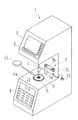
以下、本発明の実施の一形態を図面に基づいて説明する。図1は本発明の装置の外観図であり、図2は装置内部の光学系の概略構成を示す図である。1は略コの字状をした側面を持つ装置本体であり、その内部には図2に示す照明光学系、撮像光学系が配置される。装置本体1の上部前面には液晶表示器等のカラーモニタ2と上部スイッチパネル3が設けられ、下部前面には下部スイッチパネル4が設けられている。モニタ2には後述するCCDカメラ17bに撮像される被加工レンズLEの像やアライメントのためのマーク、レイアウト画面等が表示される。
【0015】
5は透明アクリルからなる円形のレンズテーブルであり、テーブル支持部6によって装置本体1の台座1aに設けられている。レンズテーブル5上の中央には所定のパターンを持つ指標部12が形成さている。本形態での指標部12は格子状に配置されたドット指標をレンズテーブル5上の上面にエッチングで形成しており、ドット指標は直径0.3mmの大きさのものがカップ取付けの基準軸線Lを中心にする20mm四方の範囲で0.3mmピッチ間隔に配置されている(図4参照)。なお、この指標部12はレンズLEに対して照明光源側に設けるようにしても良い。
【0016】
7は加工治具であるカップ19をレンズに取り付けるためのカップ取付部である。カップ取付部7は、装置本体1内部に設けられたモータ31、モータ32(図3参照)により回転上下動するシャフト7aと、シャフト7aに固定されたアーム7bを備える。アーム7bの先端の下部には、カップ19が持つ基部を装着する装着部7cが設けられている。カップ19はアーム7bの上面に添付された位置決めマークに従い、所定の方向に取り付ける。シャフト7aとともにアーム7bが点線で示す位置に回転すると、カップ19の中心は基準軸線L上に来るようになっている。なお、カップ取付部7の移動機構は本形態のように回転機構で構成する他、水平移動機構で構成するこもできる。
【0017】
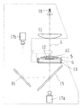
図2において、10は照明光源、11はコリメータレンズ11であり、コリメータレンズ11の光軸は基準軸線Lと略一致しており、コリメータレンズ11の後側焦点付近に照明光源10が位置する。照明光源10からの照明光はコリメータレンズ11によりレンズLEより一回り大きな径の略平行光束とされ、レンズテーブル5上に置かれるレンズLEに投光される。
【0018】
レンズテーブル5の下方には、すりガラス等の半透明の材質で作られたスクリーン板13が配置されている。レンズLEを透過した光束はレンズテーブル5上の指標部12を照明し、スクリーン板13にはレンズLEの全体像、及びレンズLEのプリズム作用を受けたドット指標像が投影される。スクリーン板13の下方にはハーフミラー15が配置されており、その透過方向の基準軸線L上には第1CCDカメラ17aが設けられている。この第1CCDカメラ17aはスクリーン板13に投影された指標像を検出できるように、カップ取付け中心となる基準軸線Lを中心にした中央領域のみを拡大して撮像する位置に置かれている。一方、ハーフミラー15の反射方向にはミラー16、ミラー16で反射する像を撮像する第2CCDカメラ17bが設けられている。この第2CCDカメラ17bはスクリーン板5に投影されるレンズLEの全体像が得られるように、スクリーン板13のほぼ全体を撮像する位置に置かれている。
【0019】
図3は装置の制御系を示す図である。第1CCDカメラ17aからの画像信号は画像処理部34に入力される。画像処理部34は、スクリーン板13に投影された指標像の位置を画像処理して検出し、その検出信号を制御部30に入力する。制御部30は入力された検出信号に基づき、レンズLEの光学中心位置、及び柱面軸の方向を求める(後述する)。一方、第2CCDカメラ17bからの画像信号は画像合成回路35に入力され、画像合成回路35は制御部30に接続された表示回路36で生成される文字やマーク等と合成してモニタ2に表示する。
【0020】
また、制御部30にはレンズ取付け部7のシャフト7aを回転するモータ31、シャフト7aを上下動するモータ32、入力されたデータ等を記憶するメモリ40、スイッチパネル3,4、眼鏡枠の形状を測定する枠形状測定装置37、レンズLEを研削加工する加工装置38が接続されている。
【0021】
次に、第1CCDカメラ17aにより得られる画像から、レンズLEの光学中心位置及び柱面軸の方向を求める方法について説明する。
【0022】
レンズLEが載置されていない場合には、指標部12のドット指標は平行光束により照明されるので、スクリーン板13にはそのまま指標像が投影される。画像処理部34は、レンズLEがない状態で第1CCDカメラ17aにより撮像された画像から指標の各ドット像の座標位置を求め、これを記憶しておく。レンズLEが載置されると、レンズLEの光学中心付近の直下に位置するドット像は、レンズLEの有無に拘わらず位置が同じであるが、光学中心でない部分のドット像はレンズLEのプリズム作用により座標位置が移動する。よって、光学中心を検出するには、レンズLEの無い状態での各ドット像の座標位置に対して、レンズLEが載せられた状態における各ドット像の座標位置の変化を調べ、各ドット像がどの位置を中心に拡散又は収束しているかを求める。すなわち、この拡散又は収束の中心が光学中心として検出できる。例えば、図4に示す例では、レンズがない状態でのドット像の座標位置がP0を中心に収束しているので、このP0の座標位置が光学中心として検出できる。ドット間に光学中心が位置する場合であっても、各ドット像の移動方向と移動量からその移動中心を補間して求めれば良い。
【0023】
レンズLEが柱面度数を持つ場合、各ドット像はレンズの母線に向かう方向(又は離れる方向)に移動する。よって、被加工レンズLEのない状態での各ドット像の座標位置に対して、各ドット像がどの方向に移動しているかを調べることにより、同様に柱面軸の方向を検出できる。
【0024】
以上のような構成を持つ装置の動作を説明する。以下ではレンズLEが単焦点レンズ、二重焦点レンズ及び累進焦点レンズである場合についてそれぞれ説明する。
【0025】
<単焦点レンズ>
まず、本体1に接続されている枠形状測定装置37でレンズLEが枠入れされる眼鏡枠の形状を予め測定した後、TRACEキー3jを押すと測定された枠形状(以下、これを玉型ともいう)のデータが入力される。入力された枠データはメモリ40に記憶されるとともに、モニタ2には入力された枠形状データに基づく玉型形状図形20が表示される(図5参照)。
【0026】
操作者は、スイッチパネル4のJOBキー4aを押した後、テンキキー4fでJOB番号を数値入力し、ENTキー4iで確定する。その後、カップ取付けを行うレンズの左右をR/Lキー4gで選択し、枠形状データに対するレンズのレイアウトやレンズのタイプ等の枠入れ条件をスイッチパネル3,4の各キーを操作して入力する。レンズLEのタイプはTYPEキー3bで選択する。
【0027】
単焦点レンズのモードでは、図5に示すように、モニタ2の画面左側にレンズをレイアウトするための入力項目が表示されるので、カーソル移動キー3iにより反転カーソル21を移動して入力項目を選択する。各入力項目の値は「+」「−」キー4h又はテンキー4fで変更でき、FPD(眼鏡枠の幾何中心間距離)、PD(瞳孔間距離)、及びU/D(眼鏡枠の幾何学中心に対する光学中心高さ)のレイアウトデータを入力する。また、レンズLEが柱面度数を持つ場合は、反転カーソル21をAXISの項目に合わせ、処方箋の軸角度を入力しておく。
【0028】
なお、データの入力時には、レイアウトデータを加工装置38側に転送してそのまま加工がスムーズに行えるように、レンズLEの材質や眼鏡枠の種類等の加工条件を、スイッチパネル3のキー3c,3e等で予め入力しておくと都合が良い。
【0029】
モニタ2の画面上には(図5参照)、玉型形状図形20の他、レンズLEに取り付けられるカップ19の形状を表す円形カップ図形23aが、カップ取付け中心である基準軸線Lに対応する画面上の位置を中心にして赤色で表示される。この円形カップ図形23aを表示するためのカップ19の形状データはメモリ40に予め記憶されている。レンズLEを載置する前の状態では、玉型形状図形20はレイアウトによる光学中心(アイポイント位置)がカップ図形23aの中心に一致した状態として表示される。また、柱面軸角度のデータを入力すると、その角度方向に傾いたラインマーク24が赤色で表示される。
【0030】
必要なデータの入力ができたら、操作者はレンズLEをレンズテーブル5に載せてカップ取り付けたのためのアライメントを行う。レンズLEの中央がレンズテーブル5の中心付近に位置するようにすると(レンズの光学中心が指標部12の指標内に入るようにすると)、スクリーン板13にはレンズLEの像及び指標部12の指標像が投影され、第2CCDカメラ17bによりレンズLEの全体像が撮像される。モニタ2の画面上にそのレンズ像LE′が映し出される(図6参照)。また、第1CCDカメラ17aによりスクリーン板13に投影された指標像が撮像される。その画像信号は画像処理部34に入力され、制御部30は画像処理部34によって検出されるドット指標像の座標位置情報に基づき、前述した方法により基準軸線Lに対する光学中心の偏位情報及び柱面軸方向の情報を連続的に得る。
【0031】
これらの情報が得られると、制御部30により制御される表示回路36によって、図6に示すように、レンズLEの光学中心を示す十字線マーク25が白色で表示される。この十字線マーク25は、中央に描かれた「○」の中心がレンズLEの光学中心に合わせて表示されるとともに、検出された柱面軸方向の情報に合わせて十字線マーク25の長軸が傾けて表示される。そして、入力された柱面軸角度方向を示す赤色のラインマーク24は、十字線マーク25の中心(レンズLEの光学中心)を基準にして表示される。
【0032】
また、玉型形状図形20はレイアウトされた光学中心がレンズLEの光学中心と一致するように表示されると共に、検出されたレンズLEの柱面軸方向に対して入力された軸角度方向が合うように表示される。この玉型形状図形20はレンズ像LE′に重ねて表示されるので、操作者はこの段階で両者を観察することによりレンズ径が加工に不足していないかの判断を即座に行うことができる。
【0033】
レンズLEの光学中心にカップを取り付けるためのアライメント操作は次のように行う。画面上の円形カップ図形23aの中心には位置合わせのターゲットとするカップ取付け中心マーク22が赤色で表示されているので、操作者はマーク22の中心と十字線マーク25の中心が一致するようにレンズLEを移動して、基準軸線Lに対するレンズLEの光学中心のアライメントを行う。柱面軸方向のアライメントについては、十字線マーク25の長軸がラインマーク24の方向に合うようにレンズLEを回転する。このとき、軸合わせの目標とするラインマーク24は検出された光学中心を基準として表示されているので、光学中心のアライメントを行いながら柱面軸方向のアライメントを平行して行える。また、柱面軸方向のアライメントを予めほぼ完了させ後に光学中心のアライメントを行うことができるので、レンズの回転移動に伴う中心ずれの度合いが少なくなり、アライメント作業の効率化を図ることができる。
【0034】
なお、モニタ2の画面左側の表示項目27a,27bには、基準軸線Lに対するレンズLEの光学中心の偏位情報がx,yによって距離数値(単位はmm)として表示され、また、表示項目27cには検出された柱面軸角度が数値表示される。操作者はこれらの表示によっても、アライメントに必要なレンズの移動や回転角度、各操作の方向を知ることができ、また、数値表示によって微細なアライメント調整量が認識できるので、アライメント操作がより簡単に行える。
【0035】
上記のアライメントによって、入力された柱面軸角度に対して検出された柱面軸角度が所定の許容範囲に入ると、図7に示すごとく、白色の十字線マーク25がラインマーク24に重なり、赤いラインマーク24の表示が消える。また、基準軸Lの位置に対して検出された光学中心が所定の許容範囲に入ると、十字線マーク25の中央に描かれた「○」にマーク22が隠れるように、マーク22の表示が消える。そして、柱面軸角度及び光学中心のアライメントが共に完了すると、カップ図形23aの色が赤色から青色に変化する。こうしたアライメント用のマークの変化、カップ図形23aの色の変化によって、操作者はアライメント完了を知ることができる。また、図8に示した例では、円形カップ図形23aが玉型形状図形20に収まっているので、加工装置38での加工に際しての加工干渉が無いことを確認できる。
【0036】
レンズLEの光学中心及び柱面軸角度のアライメントが完了したら、操作者はカップの取付けを指示するためのBLOCKキー4kをONする。制御部30はモータ31を駆動してカップ19が基準軸線L上に来るようにシャフト7aを回転した後、モータ32を駆動してカップ19を下降させ、レンズLE上にカップ19を固定させる。
【0037】
以上、レンズLEの光学中心にカップを取り付ける場合を説明したが、本装置では任意の位置にカップを取付け、その取付け位置情報を加工装置38による加工時に座標変換する補正情報として使用することも可能である。この場合のレンズLEのアライメントについては、図6に示すように、カップ図形23aが玉型形状図形20の中に収まるようにレンズLEを移動すれば、カップ6aが加工干渉を起こすことがないようにできるので、この状態でカップ取付けが可能となる。
【0038】
柱面軸方向のアライメントについても、入力された軸角度と検出された軸角度とのずれ情報が得られ、このずれ情報をも加工装置38側で補正されるため、正確なアライメントは不要である。玉型形状図形20は検出された軸角度方向に対応して表示されるので(すなわち軸角度のずれ量に応じて傾いて表示される)、カップ図形23aが玉型形状図形20の中に収まるかを確認すれば加工干渉を避けた位置にカップを取り付けることができる。
【0039】
なお、カップ取付けを行うときは、JOBキー4a及びテンキー4fを操作して予めJOB番号を入力しておくことにより、メモリ40に記憶される玉型形状データやレイアウトデータ、光学中心位置の偏位情報及び軸角度のずれ情報等はJOB番号によって管理されるようになる。
【0040】
<二重焦点レンズ>
前述と同様に枠形状データを入力した後、TYPEキー3bで二重焦点レンズのモードを選択する。モニタ2の画面上には、図8に示すように、カップ取付け中心を示すマーク22に対し、予め設定された偏位量分だけずれた位置に二重焦点レンズの小玉形状を模した小玉マーク50が表示されると共に、小玉マーク50の左右端には2mm間隔の3本の縦スケール51L、同じく2mm間隔の3本の縦スケール51Rが表示される。小玉マーク50の上境線中心マーク50aがレンズLEの小玉部分を位置合わせする基準となり、縦スケール51L,51Rは左右中心合わせのガイドとなる。また、カップ取付け中心(マーク22)を基準にして水平スケール52が1mmピッチ間隔で複数本表示され、この水平スケール52が小玉部分を水平に軸合わせするためのガイドとなる。
【0041】
モニタ2の画面左側にレンズをレイアウトするための入力項目が表示される。項目55aには近用の瞳孔間距離を入力し、項目55bには小玉上境線の中心からその真下の玉型底辺までの距離を入力する。これにより玉型形状図形20の表示位置が決まり、枠形状データに対するレンズのレイアウトができる。
【0042】
なお、図8はR/Lキー4gで右レンズを選択した例であり、左レンズを選択した場合は、小玉マーク50、縦スケール51L,51Rの表示位置がカップ取付け中心マーク22を中心にして左右反転した位置に変更される。
【0043】
二重焦点レンズの位置合わせは次のようにする。レンズ(二重焦点レンズ)LEをレンズテーブル5に載せると、平行光束で照明された二重焦点レンズの小玉像がスクリーン板13に鮮明に投影される。これがCCDカメラ17bにより撮像され、図9に示すように、モニタ2上にはレンズ像LE′及び小玉像58が表示される。操作者は小玉像58の上境線中心が小玉マーク50側の上境線中心50aに重なるようにレンズLEを移動する。レンズの種類により小玉部分の大きさは異なるが、小玉マーク50の左右に対称に表示されている縦スケール51L,51Rをガイドにして小玉像58の左右が均等になるようにすることにより、上境線中心の位置合わせを容易に行うことができる。また、水平スケール52にしたがって小玉像58の水平軸が傾かないように合せる。
【0044】
ここで、二重焦点レンズの場合、小玉部分に対するカップ19を取り付ける位置は固定的で無く、加工業者(眼鏡店)の方針やレンズメーカによって異なる。このような場合でも上記のようなモニタ2に表示される小玉マーク50にしたがった位置合わせが容易に行えるように、本装置では小玉マーク50の表示位置(レイアウト)を任意に変更できるようになっている。
【0045】
二重焦点レンズの小玉部分に対するカップ取付け位置を変更する場合は、BX項目56a,BY項目56bの値を変更することにより小玉マーク50の表示位置が変更される。項目56aはカップ取付け位置を小玉上境線の中心から上にずらす距離(mm)を示し、項目56bは小玉上境線の中心の外側にずらす距離を示す。項目56a,56bの値はそれぞれカーソル移動キー3iにより反転カーソル21を合わせ、テンキー4fで所望する値を設定した後、ENTキー4iで確定する。これにより、モニタ2上のカップ取付け中心を示すマーク22に対する小玉マーク50の水平方向及び垂直(高さ)方向の表示位置が変更される。また、小玉マーク50の表示位置の変更に連動して縦スケール51L,51Rも移動して表示される(図10参照)。モニタ2上のこれらの表示は制御部30により表示回路36を介して制御される。レンズの位置合わせは、上記と同じように小玉マーク50、縦スケール51L,51R及び水平スケール52に対する小玉像58の位置を確認しながら合せる。
【0046】
こうして位置合わせができたら、レンズ像LE′と玉型形状図形20の比較によるレンズ径についての加工可否の確認、カップ図形23aと玉型形状図形20の比較による加工干渉の確認をし、BLOKキー4kを押してカップ取付部7を作動させ、カップ19を取り付ける。カップ取付けと同時に設定されている加工条件、レイアウトデータ(BX項目56a,BY項目56bの値も含む)及び枠形状データが共にJOB番号と対応付けてメモリ40に記憶される。
【0047】
装置本体1と加工装置38がデータ通信可能に接続されている場合は、JOB番号を指定してメモリ40に記憶されているデータを加工装置38側へ入力することができる。加工装置38としては、例えば、本出願人による特開平9−253999号公報のものが使用できる。加工装置38は被加工レンズLEを2つのレンズ回転軸38cにチャッキングし、加工砥石38dの砥石回転軸とレンズ回転軸38cの軸間距離を変える移動機構38eを動作させることにより、入力されたデータに基づいて加工を行う。二重焦点レンズのモードでカップ取付けをした時は、カップ取付け中心と小玉部分の位置関係のデータ(前述のBX項目56a,BY項目56bの値)も入力されるので、加工装置38側ではこのデータを基にして加工データを算出する。
【0048】
<累進焦点レンズ>
前述と同様に枠形状データを入力した後、TYPEキー3bで累進焦点レンズのモードを選択する。累進焦点レンズに印刷されている遠用アイポイント位置や水平方向を示すレイアウトマークを使用し、遠用アイポイント位置にカップを取り付ける場合は次のようにする。レンズLEをレンズテーブル5に載せると、スクリーン板13にはレンズ像と共にレイアウトマーク像が明確に投影され、これがカメラ17bに撮像されてモニタ2上に表示される。
【0049】
図11はこのときの画面例であり、モニタ2の画面左側に表示されている入力項目に従い、累進焦点レンズのレイアウトデータを入力しておくことにより、玉型形状図形20の表示位置が決められる。操作者はモニタ2上に表示された遠用アイポイントマーク像60、水平線マーク像61を観察し、遠用アイポイントマーク像60をカップ取付け中心マーク22に一致するように移動する。また、水平線マーク像61が水平スケール62に対して傾かないように合せることにより軸合わせができる。位置合わせ用のマークである水平スケール62はカップ取付け中心マーク22を基準にして1mmピッチ間隔で複数本表示さる。
【0050】
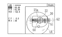
累進焦点レンズの隠しマークを使用して、遠用アイポイント位置にカップを取り付ける場合は次のようにする。累進焦点レンズのレンズ表面には、通常、2つの隠しマークが施されているので、これを確認して予めペン等によって印を付して置く。また、レアウトデータとして、図12に示すEP項目66にはレンズの隠しマークからの遠用アイポイント高さの距離(EP値)を、前述のレイアウトデータ入力と同様にテンキー4f等で入力しておく。このEP値はメーカ毎の累進焦点レンズの種類により予め定められているので、これを確認して知ることができる。EP値を入力することにより、水平スケール62及び水平中心枠マーク62aの表示位置がカップ取付け中心マーク22に対して入力値分だけずれて表示される。図12の例の場合3.5mm分だけ下側へずれて表示されている。
【0051】
レンズLEをレンズテーブル5に載せると、図12に示すように、モニタ2上には2つの隠しマークの印像69が映し出されるので、2つの印像69が水平中心枠マーク62a内に一致するようにレンズLEを移動する。また、累進焦点モードでは左右の位置合せマークとして、カップ取付け中心マーク22を中心にして左に2mm間隔の3本の縦スケール63L、右に2mm間隔の3本の縦スケール63Rが左右対称に表示されるので、これをガイドとして隠しマークの2つの印像69が左右で均等になるように合せる。
【0052】
ここで、縦スケール63Lと縦スケール63Rの間隔はレイアウト項目67の距離値(WD値)によって変更可能となっている。累進焦点レンズに施されている2つの隠しマークの間隔は、レンズメーカやレンズの種類によって異なる。この場合には2つの隠しマークの間隔に合せて縦スケール63Lと縦スケール63Rとの間隔(センターのスケールを基準としている)を予め変更しておく。項目67のWD値の変更は、他の項目と同様にスイッチパネル3,4のキー操作で所望する値を入力して行うことができる。WD値の変更により縦スケール63Lと縦スケール63Rの表示位置が変更され、隠しマークの印像69を左右均等に位置合わせする確認が行いやすくなる。
【0053】
以上のようにしてレンズLEの位置合わせができたら、加工径及びカップとの加工干渉を確認した後、BLOKキー4kを押してカップ19を取り付ける。
【0054】
【発明の効果】
以上説明したように、本発明によれば、カップ取付けを精度良く容易に行うことができる。
【図面の簡単な説明】
【図1】本発明に係る装置の外観図である。
【図2】装置の光学系の概略構成を示す図である。
【図3】装置の制御系を示す図である。
【図4】指標像からレンズの光学中心を検出する方法を説明する図である。
【図5】単焦点レンズのモードでの画面例を示す図である。
【図6】単焦点レンズを載せたときの画面例を示す図である。
【図7】単焦点レンズのアラインメントが完了したときの画面例を示す図である。
【図8】二重焦点レンズのモードでの画面例を示す図である。
【図9】二重焦点レンズの位置合わせを説明する図である。
【図10】二重焦点レンズの小玉部分に対する位置合わせを変更した場合の画面例を示す図である。
【図11】累進焦点レンズのモードでの画面例を示す図である。
【図12】累進焦点レンズの隠しマークを使用した位置合わせを説明する図である。
【符号の説明】
1 装置本体
2 モニタ
3 スイッチパネル
7 カップ取付部
10 照明光源
13 スクリーン
17a 第1CCDカメラ
17b 第2CCDカメラ
22 カップ取付け中心マーク
23a カップ図形
30 制御部
36 表示回路
50 小玉マーク
50a 上境線中心マーク
51L,51R 縦スケール
58 小玉像
62 水平スケール
62a 水平中心枠マーク
69 印像
63L,63R 縦スケール[0001]
BACKGROUND OF THE INVENTION
The present invention relates to a cup attachment device for attaching a cup (a processing jig such as a leap cup attached via a suction cup and an adhesive sheet) used for processing a peripheral edge of a spectacle lens to a lens to be processed.
[0002]
[Prior art]
Conventionally, this type of cup mounting apparatus illuminates a scale plate and a lens to be processed with a scale, projects a mark point and a scale plate applied to the lens with a lens meter or the like on a screen, and displays an image on the screen. Observed and aligned for cup attachment.
[0003]
Also, in the case of a bifocal lens, observe the small ball part, and in the case of a progressive focus lens, observe the layout mark or hidden mark (pre-marked) printed on the lens surface. Alignment was performed based on this and the scale plate image.
[0004]
[Problems to be solved by the invention]
However, there are various types of lenses, and in particular, the mounting position of the cup of the bifocal lens and the progressive focus lens differs depending on the lens. Therefore, it was not easy to mount the cup with high precision by positioning according to the conventional scale plate. .
[0005]
An object of the present invention is to provide a cup mounting device that can easily and accurately perform cup mounting in view of the above-described problems of the prior art.
[0006]
[Means for Solving the Problems]
In order to solve the above problems, the present invention is characterized by having the following configuration.
[0007]
(1) An input means for inputting the type of lens to be processed, a data input means for inputting data for laying out the cup mounting center for the small lens portion of the bifocal lens, and a diameter larger than the diameter of the lens to be processed An imaging unit that illuminates the lens to be processed with a light beam and images the lens to be processed, and a display unit that displays a small ball mark imitating a small ball on the lens image based on the data input to the data input unit and displays it on the display screen And a cup mounting device for mounting a cup used for processing a peripheral edge of a spectacle lens to a lens to be processed, in order to align the left and right positions of the small lens image of the double focus lens , Vertical scale display control means for displaying the vertical scale inside and outside the edge of each of them and displaying them symmetrically with the small ball mark as the center It is characterized by that.
[0014]
DETAILED DESCRIPTION OF THE INVENTION
Hereinafter, an embodiment of the present invention will be described with reference to the drawings. FIG. 1 is an external view of an apparatus of the present invention, and FIG. 2 is a diagram showing a schematic configuration of an optical system inside the apparatus.
[0015]
A circular lens table 5 made of transparent acrylic is provided on the base 1 a of the apparatus
[0016]
[0017]
In FIG. 2,
[0018]
A
[0019]
FIG. 3 is a diagram showing a control system of the apparatus. An image signal from the
[0020]
The
[0021]
Next, a method for obtaining the optical center position of the lens LE and the direction of the columnar axis from the image obtained by the
[0022]
When the lens LE is not placed, the dot index of the
[0023]
When the lens LE has a column surface power, each dot image moves in a direction toward (or away from) the generatrix. Therefore, the direction of the column surface axis can be detected in the same manner by examining in which direction each dot image is moving with respect to the coordinate position of each dot image without the lens LE being processed.
[0024]
The operation of the apparatus having the above configuration will be described. Hereinafter, the case where the lens LE is a single focus lens, a bifocal lens, and a progressive focus lens will be described.
[0025]
<Single focus lens>
First, the frame
[0026]
After the operator presses the JOB key 4a on the
[0027]
In the single focus lens mode, as shown in FIG. 5, the input items for laying out the lens are displayed on the left side of the screen of the
[0028]
At the time of data input, the processing conditions such as the material of the lens LE and the type of the spectacle frame are set to the keys 3c and 3e of the
[0029]
On the screen of the monitor 2 (see FIG. 5), in addition to the target lens shape figure 20, a circular cup figure 23a representing the shape of the
[0030]
When the necessary data can be input, the operator performs alignment for mounting the lens LE on the lens table 5 and attaching the cup. When the center of the lens LE is positioned near the center of the lens table 5 (when the optical center of the lens is within the index of the index unit 12), the image of the lens LE and the
[0031]
When these pieces of information are obtained, the
[0032]
In addition, the target lens shape figure 20 is displayed so that the laid-out optical center coincides with the optical center of the lens LE, and the input axial angle direction matches the detected columnar axial direction of the lens LE. Is displayed. Since the target lens shape figure 20 is displayed so as to overlap the lens image LE ′, the operator can immediately determine whether the lens diameter is insufficient for processing by observing both at this stage. .
[0033]
An alignment operation for attaching the cup to the optical center of the lens LE is performed as follows. At the center of the circular cup figure 23a on the screen, the cup
[0034]
In the
[0035]
When the column surface axis angle detected with respect to the input column surface axis angle falls within a predetermined allowable range by the above alignment, as shown in FIG. 7, the
[0036]
When the alignment of the optical center of the lens LE and the column surface axis angle is completed, the operator turns on the BLOCK key 4k for instructing the attachment of the cup. The
[0037]
As described above, the case where the cup is attached to the optical center of the lens LE has been described. However, in this apparatus, the cup can be attached at an arbitrary position, and the attachment position information can be used as correction information for coordinate conversion during processing by the
[0038]
As for the alignment in the axial direction of the column surface, deviation information between the input axis angle and the detected axis angle is obtained, and this deviation information is also corrected on the
[0039]
When attaching the cup, by operating the JOB key 4a and the numeric key 4f and inputting the JOB number in advance, the target lens shape data and layout data stored in the
[0040]
<Double focus lens>
After inputting the frame shape data as described above, the mode of the bifocal lens is selected with the TYPE key 3b. On the screen of the
[0041]
Input items for laying out the lens are displayed on the left side of the screen of the
[0042]
FIG. 8 shows an example in which the right lens is selected with the R / L key 4g. When the left lens is selected, the display positions of the
[0043]
The alignment of the bifocal lens is as follows. When the lens (bifocal lens) LE is placed on the lens table 5, a small lens image of the bifocal lens illuminated with a parallel light beam is projected clearly on the
[0044]
Here, in the case of a bifocal lens, the position where the
[0045]
When changing the cup mounting position with respect to the small lens portion of the bifocal lens, the display position of the
[0046]
When the alignment is completed in this way, the lens image LE ′ and the target lens shape figure 20 are compared to confirm whether the lens diameter can be processed, the
[0047]
When the apparatus
[0048]
<Progressive focus lens>
After inputting the frame shape data as described above, the progressive focus lens mode is selected with the TYPE key 3b. When the distance eye point position printed on the progressive focus lens and the layout mark indicating the horizontal direction are used and the cup is attached to the distance eye point position, the following is performed. When the lens LE is placed on the lens table 5, a layout mark image is clearly projected on the
[0049]
FIG. 11 shows an example of the screen at this time, and the display position of the target lens shape figure 20 is determined by inputting the layout data of the progressive focus lens according to the input items displayed on the left side of the screen of the
[0050]
When attaching the cup to the distance eye point position using the hidden mark of the progressive focus lens, do as follows. Since the lens surface of the progressive focus lens is usually provided with two hidden marks, this is confirmed and marked with a pen or the like in advance. As layout data, the distance (EP value) of the distance eye point height from the hidden mark of the lens is input to the
[0051]
When the lens LE is placed on the lens table 5, as shown in FIG. 12, two
[0052]
Here, the interval between the
[0053]
After the alignment of the lens LE is completed as described above, after confirming the processing diameter and processing interference with the cup, the
[0054]
【The invention's effect】
As described above, according to the present invention, it is possible to easily and accurately attach the cup.
[Brief description of the drawings]
FIG. 1 is an external view of an apparatus according to the present invention.
FIG. 2 is a diagram showing a schematic configuration of an optical system of the apparatus.
FIG. 3 is a diagram showing a control system of the apparatus.
FIG. 4 is a diagram illustrating a method for detecting the optical center of a lens from an index image.
FIG. 5 is a diagram illustrating an example of a screen in a single focus lens mode.
FIG. 6 is a diagram illustrating an example of a screen when a single focus lens is mounted.
FIG. 7 is a diagram illustrating an example of a screen when alignment of a single focus lens is completed.
FIG. 8 is a diagram illustrating an example of a screen in a bifocal lens mode.
FIG. 9 is a diagram for explaining alignment of a bifocal lens.
FIG. 10 is a diagram showing an example of a screen when the alignment with respect to the small lens portion of the bifocal lens is changed.
FIG. 11 is a diagram illustrating a screen example in a progressive focus lens mode.
FIG. 12 is a diagram illustrating alignment using a hidden mark of a progressive focus lens.
[Explanation of symbols]
DESCRIPTION OF
Claims (1)
Priority Applications (5)
| Application Number | Priority Date | Filing Date | Title |
|---|---|---|---|
| JP2000134250A JP3842953B2 (en) | 2000-04-28 | 2000-04-28 | Cup mounting device |
| ES01110463T ES2258043T3 (en) | 2000-04-28 | 2001-04-27 | SUCTION CUP UNIT. |
| DE60117067T DE60117067T2 (en) | 2000-04-28 | 2001-04-27 | Napfbefestigungsvorrichtung |
| EP01110463A EP1149664B1 (en) | 2000-04-28 | 2001-04-27 | Cup attaching apparatus |
| US09/842,626 US6599171B2 (en) | 2000-04-28 | 2001-04-27 | Cup attaching apparatus |
Applications Claiming Priority (1)
| Application Number | Priority Date | Filing Date | Title |
|---|---|---|---|
| JP2000134250A JP3842953B2 (en) | 2000-04-28 | 2000-04-28 | Cup mounting device |
Publications (3)
| Publication Number | Publication Date |
|---|---|
| JP2001311919A JP2001311919A (en) | 2001-11-09 |
| JP2001311919A5 JP2001311919A5 (en) | 2005-05-12 |
| JP3842953B2 true JP3842953B2 (en) | 2006-11-08 |
Family
ID=18642560
Family Applications (1)
| Application Number | Title | Priority Date | Filing Date |
|---|---|---|---|
| JP2000134250A Expired - Lifetime JP3842953B2 (en) | 2000-04-28 | 2000-04-28 | Cup mounting device |
Country Status (5)
| Country | Link |
|---|---|
| US (1) | US6599171B2 (en) |
| EP (1) | EP1149664B1 (en) |
| JP (1) | JP3842953B2 (en) |
| DE (1) | DE60117067T2 (en) |
| ES (1) | ES2258043T3 (en) |
Cited By (1)
| Publication number | Priority date | Publication date | Assignee | Title |
|---|---|---|---|---|
| WO2021059515A1 (en) * | 2019-09-27 | 2021-04-01 | 株式会社レクザム | Lens optical-characteristics-measuring device, lens optical-characteristics-measuring method, program, and recording medium |
Families Citing this family (11)
| Publication number | Priority date | Publication date | Assignee | Title |
|---|---|---|---|---|
| JP2002139713A (en) | 2000-10-31 | 2002-05-17 | Hoya Corp | Method and device for mounting lens holders of spectacle lens |
| US6837580B2 (en) * | 2001-10-26 | 2005-01-04 | Pentax Corporation | Progressive power lens |
| JP4541017B2 (en) * | 2004-03-31 | 2010-09-08 | 株式会社トプコン | Lens suction jig mounting device |
| EP1736816B1 (en) * | 2004-03-31 | 2012-06-13 | Topcon Corporation | Device for installing suction jig for eyeglass lens and method for determining suction jig installation position |
| JP4756828B2 (en) * | 2004-04-27 | 2011-08-24 | 株式会社ニデック | Lens meter |
| FR2900246B1 (en) * | 2006-04-20 | 2008-07-04 | Essilor Int | METHOD FOR DETECTING AN OPTICAL REFERENTIAL OF AN OPHTHALMIC LENS |
| FR2983313B1 (en) * | 2011-11-29 | 2014-06-27 | Essilor Int | OPHTHALMIC LENS HOLDER FOR CENTERING DEVICE |
| KR101352377B1 (en) | 2012-01-20 | 2014-01-24 | 한국지질자원연구원 | Photographing apparatus |
| JP6543464B2 (en) * | 2014-12-26 | 2019-07-10 | ホヤ レンズ タイランド リミテッドHOYA Lens Thailand Ltd | Eyeglass lens |
| JP7087366B2 (en) | 2017-12-05 | 2022-06-21 | 株式会社ニデック | Axis setting device, spectacle lens processing system, and spectacle lens processing method |
| EP3943240A1 (en) | 2020-07-24 | 2022-01-26 | Essilor International | Centering apparatus and process |
Family Cites Families (17)
| Publication number | Priority date | Publication date | Assignee | Title |
|---|---|---|---|---|
| DE1948644A1 (en) * | 1969-09-26 | 1971-04-01 | Zeiss Carl Fa | Device for aligning a raw-edged lens with the template for its frame |
| DE2220373A1 (en) * | 1972-04-26 | 1973-11-15 | Wernicke & Co Kg | DEVICE FOR CENTERING EYEGLASSES, IN PARTICULAR OF EYEGLASSES WITH SEAMING PART, AND FOR ATTACHING A HOLDING PART TO THE EYEGLASSES |
| FR2582975B1 (en) | 1985-06-10 | 1987-08-28 | Briot Int | APPARATUS FOR CENTERING AND POSITIONING AN ADAPTER ON AN OPTICAL GLASS BLANK AND FOR CONTROLLING A GRINDER |
| FR2607268B1 (en) | 1986-11-26 | 1990-06-08 | Essilor Int | CENTERING APPARATUS FOR OPHTHALMIC LENS |
| DE3829488A1 (en) | 1988-08-31 | 1990-03-01 | Wernicke & Co Gmbh | Device for centring spectacle glasses and applying a holding part thereon as well as an application of the device |
| EP0363281B1 (en) | 1988-10-05 | 1997-05-28 | Kabushiki Kaisha TOPCON | Lens meter |
| JP2801620B2 (en) | 1988-10-05 | 1998-09-21 | 株式会社トプコン | Lens meter |
| ES2014801A6 (en) | 1989-07-17 | 1990-07-16 | Indo International S A | Apparatus for centering and blocking ophtalmic lenses. |
| JPH03113415A (en) | 1989-09-27 | 1991-05-14 | Topcon Corp | Axis aligning device |
| US5155940A (en) | 1989-10-30 | 1992-10-20 | Kabushiki Kaisha Topcon | Apparatus for judging whether an uncut lens should be machined or not and lens grinding machine having the same |
| JP3011526B2 (en) | 1992-02-04 | 2000-02-21 | 株式会社ニデック | Lens peripheral processing machine and lens peripheral processing method |
| JP4034842B2 (en) | 1996-03-26 | 2008-01-16 | 株式会社ニデック | Lens grinding machine |
| JP2786848B2 (en) | 1997-02-07 | 1998-08-13 | 株式会社トプコン | Image display device of adsorbed lens |
| ES2136541B1 (en) | 1997-05-06 | 2000-08-01 | Indo Int Sa | DEVICE FOR THE CENTERING AND LOCKING OF AN OPHTHALMIC LENS DISC. |
| DE69920542T3 (en) | 1998-01-30 | 2012-05-24 | Nidek Co., Ltd. | Device for attaching a holding part |
| JP3828686B2 (en) | 1999-08-31 | 2006-10-04 | 株式会社ニデック | Cup mounting device |
| FR2799545B1 (en) * | 1999-10-07 | 2002-01-18 | Briot Int | METHOD AND APPARATUS FOR CENTERING AN OPHTHALMIC LENS |
-
2000
- 2000-04-28 JP JP2000134250A patent/JP3842953B2/en not_active Expired - Lifetime
-
2001
- 2001-04-27 DE DE60117067T patent/DE60117067T2/en not_active Expired - Lifetime
- 2001-04-27 EP EP01110463A patent/EP1149664B1/en not_active Expired - Lifetime
- 2001-04-27 US US09/842,626 patent/US6599171B2/en not_active Expired - Lifetime
- 2001-04-27 ES ES01110463T patent/ES2258043T3/en not_active Expired - Lifetime
Cited By (1)
| Publication number | Priority date | Publication date | Assignee | Title |
|---|---|---|---|---|
| WO2021059515A1 (en) * | 2019-09-27 | 2021-04-01 | 株式会社レクザム | Lens optical-characteristics-measuring device, lens optical-characteristics-measuring method, program, and recording medium |
Also Published As
| Publication number | Publication date |
|---|---|
| ES2258043T3 (en) | 2006-08-16 |
| EP1149664B1 (en) | 2006-02-08 |
| US6599171B2 (en) | 2003-07-29 |
| EP1149664A2 (en) | 2001-10-31 |
| EP1149664A3 (en) | 2004-01-14 |
| JP2001311919A (en) | 2001-11-09 |
| DE60117067D1 (en) | 2006-04-20 |
| US20010035937A1 (en) | 2001-11-01 |
| DE60117067T2 (en) | 2006-07-13 |
Similar Documents
| Publication | Publication Date | Title |
|---|---|---|
| JP4068233B2 (en) | Cup mounting device | |
| JP4920284B2 (en) | Cup mounting device | |
| EP1997585A1 (en) | Cup attaching apparatus | |
| JP3842953B2 (en) | Cup mounting device | |
| US6427094B1 (en) | Axial alignment apparatus, an eyeglass lens processing system and an eyeglass lens processing preparation system having the apparatus | |
| JP3828686B2 (en) | Cup mounting device | |
| KR101381121B1 (en) | Cup attaching apparatus | |
| JPS61200441A (en) | Lens meter and method for measuring progressive multifocus lens using the same | |
| KR101126303B1 (en) | Method for manually centering an ophthalmic lens, method for centering/blocking an ophthalmic lens, and centering/blocking device | |
| JPH11216650A (en) | Centering device | |
| EP0933163B2 (en) | Cup attaching apparatus | |
| US6798501B1 (en) | Cup attaching apparatus | |
| JP4104297B2 (en) | Cup mounting device | |
| JP4920285B2 (en) | Cup mounting device | |
| JP2019098484A (en) | Axial alignment device, device for lens processing, spectacle lens processing system, and spectacle lens processing method | |
| JP3828685B2 (en) | Cup mounting device | |
| JPH0679600A (en) | Positioning device for spectacle lens | |
| JP2829453B2 (en) | Lens meter | |
| JP2577700B2 (en) | Lens meter | |
| JPH09248746A (en) | Collimating machine | |
| JPH0566179A (en) | Lens meter | |
| JPH06194268A (en) | Lens meter | |
| JP2577700C (en) |
Legal Events
| Date | Code | Title | Description |
|---|---|---|---|
| A521 | Written amendment |
Free format text: JAPANESE INTERMEDIATE CODE: A523 Effective date: 20040702 |
|
| A621 | Written request for application examination |
Free format text: JAPANESE INTERMEDIATE CODE: A621 Effective date: 20040702 |
|
| A977 | Report on retrieval |
Free format text: JAPANESE INTERMEDIATE CODE: A971007 Effective date: 20051220 |
|
| A131 | Notification of reasons for refusal |
Free format text: JAPANESE INTERMEDIATE CODE: A131 Effective date: 20060110 |
|
| A521 | Written amendment |
Free format text: JAPANESE INTERMEDIATE CODE: A523 Effective date: 20060313 |
|
| A02 | Decision of refusal |
Free format text: JAPANESE INTERMEDIATE CODE: A02 Effective date: 20060411 |
|
| A521 | Written amendment |
Free format text: JAPANESE INTERMEDIATE CODE: A523 Effective date: 20060612 |
|
| A911 | Transfer to examiner for re-examination before appeal (zenchi) |
Free format text: JAPANESE INTERMEDIATE CODE: A911 Effective date: 20060621 |
|
| TRDD | Decision of grant or rejection written | ||
| A01 | Written decision to grant a patent or to grant a registration (utility model) |
Free format text: JAPANESE INTERMEDIATE CODE: A01 Effective date: 20060726 |
|
| A61 | First payment of annual fees (during grant procedure) |
Free format text: JAPANESE INTERMEDIATE CODE: A61 Effective date: 20060811 |
|
| R150 | Certificate of patent or registration of utility model |
Free format text: JAPANESE INTERMEDIATE CODE: R150 Ref document number: 3842953 Country of ref document: JP Free format text: JAPANESE INTERMEDIATE CODE: R150 |
|
| FPAY | Renewal fee payment (event date is renewal date of database) |
Free format text: PAYMENT UNTIL: 20090818 Year of fee payment: 3 |
|
| FPAY | Renewal fee payment (event date is renewal date of database) |
Free format text: PAYMENT UNTIL: 20100818 Year of fee payment: 4 |
|
| FPAY | Renewal fee payment (event date is renewal date of database) |
Free format text: PAYMENT UNTIL: 20110818 Year of fee payment: 5 |
|
| FPAY | Renewal fee payment (event date is renewal date of database) |
Free format text: PAYMENT UNTIL: 20110818 Year of fee payment: 5 |
|
| FPAY | Renewal fee payment (event date is renewal date of database) |
Free format text: PAYMENT UNTIL: 20120818 Year of fee payment: 6 |
|
| FPAY | Renewal fee payment (event date is renewal date of database) |
Free format text: PAYMENT UNTIL: 20130818 Year of fee payment: 7 |
|
| S531 | Written request for registration of change of domicile |
Free format text: JAPANESE INTERMEDIATE CODE: R313531 |
|
| R350 | Written notification of registration of transfer |
Free format text: JAPANESE INTERMEDIATE CODE: R350 |
|
| R250 | Receipt of annual fees |
Free format text: JAPANESE INTERMEDIATE CODE: R250 |
|
| R250 | Receipt of annual fees |
Free format text: JAPANESE INTERMEDIATE CODE: R250 |
|
| R250 | Receipt of annual fees |
Free format text: JAPANESE INTERMEDIATE CODE: R250 |
|
| R250 | Receipt of annual fees |
Free format text: JAPANESE INTERMEDIATE CODE: R250 |
|
| EXPY | Cancellation because of completion of term |