EP1199727B1 - Heizkabel - Google Patents
Heizkabel Download PDFInfo
- Publication number
- EP1199727B1 EP1199727B1 EP01308865A EP01308865A EP1199727B1 EP 1199727 B1 EP1199727 B1 EP 1199727B1 EP 01308865 A EP01308865 A EP 01308865A EP 01308865 A EP01308865 A EP 01308865A EP 1199727 B1 EP1199727 B1 EP 1199727B1
- Authority
- EP
- European Patent Office
- Prior art keywords
- heating
- conductors
- sheath
- outer sheath
- heating cable
- Prior art date
- Legal status (The legal status is an assumption and is not a legal conclusion. Google has not performed a legal analysis and makes no representation as to the accuracy of the status listed.)
- Expired - Lifetime
Links
- 238000010438 heat treatment Methods 0.000 title claims abstract description 60
- 239000004020 conductor Substances 0.000 claims abstract description 54
- 229910052751 metal Inorganic materials 0.000 claims abstract description 17
- 239000002184 metal Substances 0.000 claims abstract description 17
- 239000010445 mica Substances 0.000 claims abstract description 9
- 229910052618 mica group Inorganic materials 0.000 claims abstract description 9
- 229910052500 inorganic mineral Inorganic materials 0.000 claims abstract description 7
- 239000011707 mineral Substances 0.000 claims abstract description 7
- 239000004411 aluminium Substances 0.000 claims description 18
- XAGFODPZIPBFFR-UHFFFAOYSA-N aluminium Chemical compound [Al] XAGFODPZIPBFFR-UHFFFAOYSA-N 0.000 claims description 18
- 229910052782 aluminium Inorganic materials 0.000 claims description 17
- PXHVJJICTQNCMI-UHFFFAOYSA-N Nickel Chemical compound [Ni] PXHVJJICTQNCMI-UHFFFAOYSA-N 0.000 claims description 8
- 239000011810 insulating material Substances 0.000 claims description 8
- 239000003381 stabilizer Substances 0.000 claims description 8
- 239000011521 glass Substances 0.000 claims description 7
- RYGMFSIKBFXOCR-UHFFFAOYSA-N Copper Chemical compound [Cu] RYGMFSIKBFXOCR-UHFFFAOYSA-N 0.000 claims description 4
- 229910052802 copper Inorganic materials 0.000 claims description 4
- 239000010949 copper Substances 0.000 claims description 4
- 229910052759 nickel Inorganic materials 0.000 claims description 4
- 238000000034 method Methods 0.000 claims description 3
- 239000003365 glass fiber Substances 0.000 abstract description 4
- 238000009413 insulation Methods 0.000 description 9
- 239000010410 layer Substances 0.000 description 9
- 238000001125 extrusion Methods 0.000 description 5
- 238000004519 manufacturing process Methods 0.000 description 5
- 239000000047 product Substances 0.000 description 5
- 239000000463 material Substances 0.000 description 4
- 238000010276 construction Methods 0.000 description 3
- 238000004078 waterproofing Methods 0.000 description 3
- 239000000853 adhesive Substances 0.000 description 2
- 230000001070 adhesive effect Effects 0.000 description 2
- 230000004323 axial length Effects 0.000 description 2
- 239000000919 ceramic Substances 0.000 description 2
- 239000000835 fiber Substances 0.000 description 2
- 239000004848 polyfunctional curative Substances 0.000 description 2
- 229920001296 polysiloxane Polymers 0.000 description 2
- 239000010935 stainless steel Substances 0.000 description 2
- 229910001220 stainless steel Inorganic materials 0.000 description 2
- 239000002966 varnish Substances 0.000 description 2
- 229910000838 Al alloy Inorganic materials 0.000 description 1
- HCHKCACWOHOZIP-UHFFFAOYSA-N Zinc Chemical compound [Zn] HCHKCACWOHOZIP-UHFFFAOYSA-N 0.000 description 1
- 229910001297 Zn alloy Inorganic materials 0.000 description 1
- 229910045601 alloy Inorganic materials 0.000 description 1
- 239000000956 alloy Substances 0.000 description 1
- 238000009422 external insulation Methods 0.000 description 1
- 239000012467 final product Substances 0.000 description 1
- 229910010272 inorganic material Inorganic materials 0.000 description 1
- 239000011147 inorganic material Substances 0.000 description 1
- 239000007788 liquid Substances 0.000 description 1
- 230000007774 longterm Effects 0.000 description 1
- 239000000395 magnesium oxide Substances 0.000 description 1
- CPLXHLVBOLITMK-UHFFFAOYSA-N magnesium oxide Inorganic materials [Mg]=O CPLXHLVBOLITMK-UHFFFAOYSA-N 0.000 description 1
- AXZKOIWUVFPNLO-UHFFFAOYSA-N magnesium;oxygen(2-) Chemical compound [O-2].[Mg+2] AXZKOIWUVFPNLO-UHFFFAOYSA-N 0.000 description 1
- 239000000696 magnetic material Substances 0.000 description 1
- 239000000203 mixture Substances 0.000 description 1
- 239000000843 powder Substances 0.000 description 1
- 238000004886 process control Methods 0.000 description 1
- 239000002356 single layer Substances 0.000 description 1
- 238000011144 upstream manufacturing Methods 0.000 description 1
- 229910052725 zinc Inorganic materials 0.000 description 1
- 239000011701 zinc Substances 0.000 description 1
Images
Classifications
-
- H—ELECTRICITY
- H01—ELECTRIC ELEMENTS
- H01B—CABLES; CONDUCTORS; INSULATORS; SELECTION OF MATERIALS FOR THEIR CONDUCTIVE, INSULATING OR DIELECTRIC PROPERTIES
- H01B7/00—Insulated conductors or cables characterised by their form
- H01B7/17—Protection against damage caused by external factors, e.g. sheaths or armouring
- H01B7/29—Protection against damage caused by extremes of temperature or by flame
- H01B7/292—Protection against damage caused by extremes of temperature or by flame using material resistant to heat
-
- H—ELECTRICITY
- H05—ELECTRIC TECHNIQUES NOT OTHERWISE PROVIDED FOR
- H05B—ELECTRIC HEATING; ELECTRIC LIGHT SOURCES NOT OTHERWISE PROVIDED FOR; CIRCUIT ARRANGEMENTS FOR ELECTRIC LIGHT SOURCES, IN GENERAL
- H05B3/00—Ohmic-resistance heating
- H05B3/40—Heating elements having the shape of rods or tubes
- H05B3/54—Heating elements having the shape of rods or tubes flexible
- H05B3/56—Heating cables
Definitions
- the present invention relates to a heating cable for use in electric trace heating applications.
- Trace heating cables fall into two general categories, that is parallel resistance cut-to-length types and series resistance fixed length types.
- parallel resistance type cables In parallel resistance type cables, generally two insulated conductors (known as buswires) extend longitudinally along the cable. A resistance heating wire is spiralled around the conductors, electrical connections being made alternately at intervals along the longitudinally extending conductors. This creates a series of short heating zones spaced apart along the length of the cable. The heating wire must be selectively insulated from the conductors and also encased within an insulating sheath.
- Available parallel trace heating cables either use polymeric external insulation sheaths which limit the use of such cables to maximum temperatures of for example 250°C, or use glass insulation for the external sheath which can operate at higher temperatures, for example above 400°C, but which are not waterproof.
- Series resistance heaters must be specifically designed so that the power produced meets the requirements for a particular length of cable. This is not convenient and represents a major constraint.
- Generally series heaters include longitudinally extending resistance wires embedded in a mineral insulation which can withstand high temperatures.
- a typical construction comprises two ni-chrome heating conductors, magnesium oxide powder insulation, and an outer stainless steel sheath. The whole construction may be drawn down from an outside diameter of typically 80mm to an outside diameter of 4mm at which point the heater is flexible to enable it to be installed relatively easily and has an electrical resistance producing a desired output per unit length.
- Unfortunately the available range of resistances is limited and, particularly, short lengths (typically less than 10 metres) with appropriate low power outputs are not available.
- parallel heaters are convenient in use but are not available in forms which combine both a high temperature withstand and a waterproof construction, whereas series heaters are available which can withstand high temperatures and are waterproof but cannot be cut to length and therefore must be designed specially to fit particular applications and are difficult to design for use in short lengths.
- US2,905,919 describes an electric cable comprising at least two conductors separated from one another by semi-conducting inorganic material, the whole being enclosed within a surrounding layer of pulverulent mineral insulating material and an outer metal sheath.
- US 4,631,392 describes an assembly comprising a flexible corrugated metal tube and an elongate resistive heating element that is within the tube and which can be connected to a power supply to provide an elongate electrical heater.
- GB 272 166A describes an electrical heating cable having a conductor made of a material with a high ohmic resistance, an insulating covering of heat-resisting material, and an outer sheath of magnetic material having a high hysteresis and eddy current loss for increasing the amount of heat generated in the cable.
- US 4,816,649 describes a flexible electrical heat element made of insulated electrical feeder conductors and one or more heating conductors looping around the insulated feeder conductors. At least two of the feeder conductors have spaced apart bare spots of removed insulation, to allow electrical contact between the feeder conductors and a heating conductor.
- a mineral insulated heating cable comprising two electrical conductors extending along the length of the cable and an array of heating elements distributed along the lengths of the cable and connected in parallel between the conductors, wherein each conductor is encased in an inner sheath of insulating material through which connections are made to each heating element, the inner sheaths and heating elements are encased in an outer sheath of insulating material, and the outer sheath is covered by a metal jacket extruded around the outer sheath.
- the term "mineral insulated” is used herein to indicate a heating cable in which all components can withstand long-term exposure to high temperatures, e.g. 250°C and above.
- insulation could be formed from for example tape manufactured from glass and/or mica.
- the invention is based on the realisation that with careful process control it is possible to extrude a jacket of for example aluminium onto a preformed trace heating cable of the parallel resistance type, the aluminium sheath making the overall assembly waterproof and therefore enabling the use within the cable of components which themselves do not have to be waterproof.
- a waterproof structure which can withstand high temperatures results.
- the conductors and the inner sheaths may be encased in an intermediate sheath of insulating material through which connections are made between each conductor and each heating element.
- the intermediate sheath may be formed from glass tape which may be coated with a stabiliser.
- the conductors may be nickel plated copper
- the heating elements may be formed from a ni-chrome resistance heating wire spiralled around the conductors
- the resistance heating wire may be in contact with the conductors through openings in the inner sheath such that the wire touches the conductors, a positive electrical connection being made between the conductors and the wire by sprayed metal.
- Metal may be sprayed onto the conductors both before and after positioning of the heating wire.
- Each inner sheath may be formed from mica tape and the outer sheath may also comprise mica tape.
- the outer sheath may also comprise glass tape which may be coated with a stabiliser.
- the stabiliser may be for example silicone varnish to provide initial waterproofing, or a ceramic fibre adhesive incorporating a rigidiser and hardener.
- the metal jacket may be of oval section to improve overall flexibility of the product.
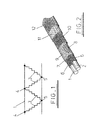
- the illustrated structure comprises two conductors 1, 2 between which a series of heating elements 3 are connected. One end of each heating element is connected to a node 4 on conductor 1 whereas the other end of each heating element is connected to a node 5 on conductor 2.
- Figure 2 illustrates a known structure resulting in an electrical arrangement as illustrated in Figure 1.
- the known cable comprises conductors 1 and 2 each received within an insulating sheath 6 of polymeric material.
- the two conductors are enclosed within a further sheath 7.
- Openings 8 are formed through the sheath 6 and 7 so as to expose the underlying conductors 1, 2 and a ni-chrome heating wire 9 is spiralled around the outside of the sheath 7 so as to contact the conductors through the openings 8.
- the heating elements 3 of Figure 1 correspond to the lengths of wire 9 between successive opening 8.
- the openings 8 will have an axial length of about 20mm and be spaced apart along the length of the cable by 750mm.
- the heating wire 9 is covered with an inner polymeric jacket 10 wrapped in a braided jacket 11 encased in a polymeric sheath 12.
- the overall structure is flexible and waterproof but cannot be used at high temperatures, for example temperatures in excess of 250°C, because such usage would result in damage to the polymeric components.
- the illustrated structure comprises two heating wires 13 and 14 embedded in a mineral insulating material 15 encased within an outer metal sheath of copper, stainless steel or nickel-based alloy.
- the heat output per unit length of such cables is a function of the composition and current through the conductors 13 and 14 and thus it is difficult to fabricate short lengths of appropriate low power and the cable cannot simply be cut to length to fit particular circumstances.
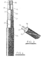
- the illustrated embodiment of the invention comprises two conductors 17, 18 each of which is covered with two layers of high temperature mica insulation tape 19 and each of which is also restrained by a high temperature glass fibre tape layer 20. Openings 21 are formed through the insulation layers 19 and 20 to enable the conductors to be contacted by a ni-chrome resistance heating wire 22 which is spiralled around the outside of the sheath 20.
- the wire 22 is covered with two layers of mica tape and an outer layer of glass fibre tape to form an insulation layer 23 which in turn is covered with an aluminium sheath 24.
- the conductors 17 and 18 may be nickel plated copper, but could also be of aluminium. There are advantages in fabricating the conductors 17 and 18 and the jacket 24 from the same material (e.g. aluminium) to avoid differential expansion between the conductors and the jacket.
- the intermediate sheath 20 may be covered with a stabiliser to provide moisture proofing and robustness during processing.
- the openings 21 may be as in prior art devices, for example typically 20mm in axial length with a space between openings of 750mm.
- the wire 22 may be spiralled around the conductors with typically eight spirals per centimetre. With such an arrangement typically ten or more spirals of resistance wire make touch contact to the conductor 17 and 18.
- the contact areas between the conductors 17 and 18 and the wire 22 may be sprayed with metal, for example aluminium, zinc or an aluminium/zinc alloy. This forms a positive electrical connection.
- the conductors 17 and 18 are sprayed before the wire 22 is positioned, and the contact areas are sprayed again after the wire 22 is positioned.
- the final insulating layer 23 which is in the form of two layers of taped mica over which a single layer of taped glass fibre is wrapped may be coated with a stabiliser for moisture protection and to improve robustness during processing.
- the stabiliser may be a simple silicone varnish or a high temperature resistant rigidiser designed to resist damage during processing and to provide initial waterproofing.
- a suitable rigidiser would be the product "901/901A ceramic fibre adhesive" incorporating a liquid insulation hardener which product is available from Symonds Cableform Limited, Welwyn Garden City, United Kingdom.
- the assembly shown in Figure 4 up to and including the sheath 23 is passed through an aluminium extruder such that the aluminium jacket 24 is extruded around the other components, forming a unitary product which is provided with reliable waterproofing by virtue of the provision of the aluminium jacket 24 and yet which only comprises components which can withstand high temperatures.
- the jacket 24 is of oval cross-section to improve the contact between the cable and a supporting surface and to improve the flexibility of the product.
- the aluminium jacket 24 may be extruded directly onto the sheath 23, but preferably is initially extruded so as to be of relatively large dimensions and then drawn down through a draw down device to be a close fit on the jacket 23.
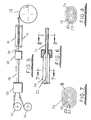
- Figure 5 illustrates a production line which incorporates such a draw down device.
- the schematically illustrated production line comprises an extruder 25 to which aluminium to be extruded is supplied from a roll 26 and to which cable incorporating all the components 17 to 23 of Figure 4 (but not the aluminium jacket 24) is supplied from a roll 27.
- the extruder 25 may be of conventional type, for example a "conform" machine arranged to produce an oval extrusion 28 the internal dimensions of which are greater than the external dimensions of the cable delivered from the roll 27.
- the extrusion 28 is a loose fit on the sheath 23.
- the "oversize" extrusion 28 is drawn down in a draw down device 29 to produce a final product 30 which corresponds to the cable structure illustrated in Figure 4 in which the aluminium jacket 24 is a close fit on the sheath 23.
- the cable 30 is pulled through the production line by conveyors 31 and wound onto a roll 32.
- this shows the outer sheath 23 of the cable delivered from the roll 27.
- the outer aluminium sheath 28 has dimensions such that a gap 33 is defined between the sheath 23 and the extrusion 28 as shown in Figure 7.
- the extrusion 28 has been converted into the close-fitting outer aluminium jacket 24 as shown in Figure 8.
Landscapes
- Resistance Heating (AREA)
- Insulated Conductors (AREA)
- Processing Of Terminals (AREA)
Claims (13)
- Mineralisoliertes Heizkabel, das aufweist: zwei elektrische Leiter, die sich entlang der Länge des Kabels erstrecken; und eine Anordnung von Heizelementen, die entlang der Länge des Kabels verteilt und parallel zwischen den Leitern geschaltet sind, wobei jeder Leiter in einer inneren Hülle aus Isoliermaterial eingeschlossen ist, durch die Verbindungen zu jedem Heizelement hergestellt werden, wobei die inneren Hüllen und die Heizelemente in einer äußeren Hülle aus Isoliermaterial eingeschlossen sind, und wobei die äußere Hülle durch eine Metallummantelung bedeckt ist, die um die äußere Hülle stranggepresst wird.
- Heizkabel nach Anspruch 1, bei dem die Leiter und die inneren Hüllen in einer Zwischenhülle aus Isoliermaterial eingeschlossen sind, durch die Verbindungen zwischen jedem Leiter und jedem Heizelement hergestellt werden.
- Heizelement nach Anspruch 2, bei dem die Zwischenhülle aus Glasband gebildet wird.
- Heizelement nach Anspruch 2 oder 3, bei dem die Zwischenhülle mit einem Stabilisator beschichtet ist.
- Heizkabel nach einem der vorhergehenden Ansprüche, bei dem die Leiter vernickeltes Kupfer sind, die Heizelemente aus einem Ni-Chrom-Widerstandsheizdraht gebildet werden, der spiralförmig um die Leiter angeordnet ist, und der Widerstandsheizdraht in Kontakt mit den Leitern durch Öffnungen in den inneren Hüllen ist, so dass der Draht die Leiter berührt, wobei eine zwangläufige elektrische Verbindung zwischen den Leitern und dem Draht durch Spritzmetall hergestellt wird.
- Heizkabel nach einem der vorhergehenden Ansprüche, bei dem jede innere Hülle aus Glimmerband hergestellt wird.
- Heizkabel nach einem der vorhergehenden Ansprüche, bei dem die äußere Hülle Glimmerband aufweist.
- Heizkabel nach einem der vorhergehenden Ansprüche, bei dem die äußere Hülle Glasband aufweist.
- Heizkabel nach Anspruch 8, bei dem das Glasband ein äußeres Teil der äußeren Hülle bildet und mit einem Stabilisator beschichtet ist.
- Heizkabel nach einem der vorhergehenden Ansprüche, bei dem die Metallummantelung einen ovalen Querschnitt aufweist.
- Heizkabel nach einem der vorhergehenden Ansprüche, bei dem die Metallummantelung aus Aluminium besteht.
- Verfahren zur Herstellung eines Heizkabels nach einem der vorhergehenden Ansprüche, das den Schritt des Bedeckens der äußeren Hülle mittels einer Metallummantelung aufweist, die um die äußere Hülle stranggepresst wird.
- Verfahren nach Anspruch 12, bei dem die Metallummantelung anfangs so stranggepresst wird, dass sie eine Spielpassung auf der äußeren Hülle aufweist, und danach gestreckt wird, um eine enge Passung auf der äußeren Hülle aufzuweisen.
Applications Claiming Priority (4)
| Application Number | Priority Date | Filing Date | Title |
|---|---|---|---|
| GB0025734 | 2000-10-19 | ||
| GB0025734A GB0025734D0 (en) | 2000-10-19 | 2000-10-19 | Heating cable |
| GB0031857 | 2000-12-30 | ||
| GB0031857A GB0031857D0 (en) | 2000-12-30 | 2000-12-30 | Heating cable |
Publications (3)
| Publication Number | Publication Date |
|---|---|
| EP1199727A2 EP1199727A2 (de) | 2002-04-24 |
| EP1199727A3 EP1199727A3 (de) | 2004-02-04 |
| EP1199727B1 true EP1199727B1 (de) | 2007-01-03 |
Family
ID=26245180
Family Applications (1)
| Application Number | Title | Priority Date | Filing Date |
|---|---|---|---|
| EP01308865A Expired - Lifetime EP1199727B1 (de) | 2000-10-19 | 2001-10-18 | Heizkabel |
Country Status (6)
| Country | Link |
|---|---|
| US (1) | US6680465B2 (de) |
| EP (1) | EP1199727B1 (de) |
| AT (1) | ATE350881T1 (de) |
| CA (1) | CA2359293C (de) |
| DE (1) | DE60125682T2 (de) |
| ES (1) | ES2278695T3 (de) |
Cited By (1)
| Publication number | Priority date | Publication date | Assignee | Title |
|---|---|---|---|---|
| WO2025168406A1 (en) * | 2024-02-06 | 2025-08-14 | Shell Internationale Research Maatschappij B.V. | Dual layer mineral insulated cable and method for heating a substance |
Families Citing this family (21)
| Publication number | Priority date | Publication date | Assignee | Title |
|---|---|---|---|---|
| AU5109099A (en) * | 1998-07-15 | 2000-02-07 | Thermon Manufacturing Company | Thermally-conductive, electrically non-conductive heat transfer material and articles made thereof |
| GB0216932D0 (en) * | 2002-07-20 | 2002-08-28 | Heat Trace Ltd | Electrical heating cable |
| US20050167134A1 (en) * | 2004-02-02 | 2005-08-04 | Philippe Charron | Heating cable substantially free from electromagnetic field |
| JP4494460B2 (ja) * | 2004-03-08 | 2010-06-30 | ヴィー・エー・テー・オートモーティヴ・システムス・アクチェンゲゼルシャフト | 平形加熱要素 |
| MX2010004331A (es) * | 2007-10-24 | 2010-06-09 | Tyco Thermal Controls Llc | Fabricacion de cable calefactor de trazado, diseño, instalacion, y manejo y metodo del mismo. |
| CA2616498C (en) * | 2007-12-28 | 2015-06-23 | Drexan Corporation | Multipurpose cable connector |
| US7989740B2 (en) | 2008-05-16 | 2011-08-02 | Thermon Manufacturing Company | Heating cable |
| US8212191B2 (en) * | 2008-05-16 | 2012-07-03 | Thermon Manufacturing Co. | Heating cable with a heating element positioned in the middle of bus wires |
| US20090283514A1 (en) * | 2008-05-16 | 2009-11-19 | Konrad Mech | Heating cable with insulated heating element |
| US10089443B2 (en) | 2012-05-15 | 2018-10-02 | Baxter International Inc. | Home medical device systems and methods for therapy prescription and tracking, servicing and inventory |
| AR084995A1 (es) * | 2011-12-01 | 2013-07-24 | Pablo Javier Invierno | Cable calefactor de tuberias de extraccion de hidrocarburos para pozos expuestos a presiones elevadas y pozos con espacio anular inundado en forma eventual, permanente o combinada |
| KR101846981B1 (ko) * | 2014-01-20 | 2018-04-09 | 김경숙 | 전열 케이블 및 이를 이용한 건식 바닥 난방 시스템 |
| WO2015128484A1 (de) * | 2014-02-28 | 2015-09-03 | Leoni Kabel Holding Gmbh | Kabelader für ein kabel, insbesondere ein induktionskabel, kabel und verfahren zur herstellung einer kabelader |
| US9881715B2 (en) | 2014-08-21 | 2018-01-30 | Trent Jason Pederson | Heated extension cord |
| CN105551693A (zh) * | 2016-01-29 | 2016-05-04 | 中国电子科技集团公司第二十三研究所 | 一种挤出式矿物绝缘射频电缆的制造方法及射频电缆 |
| CN105869747A (zh) * | 2016-05-20 | 2016-08-17 | 安徽德源电缆集团有限公司 | 一种矿用耐酸碱耐高温屏蔽电缆 |
| CN106128605A (zh) * | 2016-08-29 | 2016-11-16 | 江苏长峰电缆有限公司 | 一种新型节能阻水电缆 |
| CN106532573A (zh) * | 2016-11-09 | 2017-03-22 | 中国化学工程第四建设有限公司 | 825型合金矿物绝缘发热电缆伴热的施工方法 |
| CN107567119A (zh) * | 2017-08-14 | 2018-01-09 | 江阴神辉电工材料有限公司 | 可裁切恒功率加热线 |
| CN109379793A (zh) * | 2018-11-16 | 2019-02-22 | 安邦电气股份有限公司 | 一种高温锅炉用自限温电伴热带 |
| CN114280742B (zh) * | 2021-11-18 | 2023-09-26 | 杭州富通通信技术股份有限公司 | 一种耐温变光缆 |
Family Cites Families (12)
| Publication number | Priority date | Publication date | Assignee | Title |
|---|---|---|---|---|
| GB272166A (en) * | 1926-06-05 | 1927-06-23 | Skandinaviske Kabel Og Gummifa | An electric heating cable |
| US2905919A (en) * | 1956-01-17 | 1959-09-22 | British Insulated Callenders | Electric heating cables |
| FR1549940A (de) * | 1967-05-23 | 1968-12-13 | ||
| US3986377A (en) * | 1973-11-21 | 1976-10-19 | Industrie Pirelli S.P.A.. | Apparatus for sheathing a cable core with core surrounded by impregnating fluid during sheathing |
| US4100673A (en) * | 1977-05-05 | 1978-07-18 | Leavines Joseph E | Method of making high temperature parallel resistance pipe heater |
| US4631392A (en) * | 1984-07-13 | 1986-12-23 | Raychem Corporation | Flexible high temperature heater |
| GB8600985D0 (en) * | 1986-01-16 | 1986-02-19 | Pyrontenax Of Canada Ltd | Electric cables |
| DE3636738A1 (de) * | 1986-10-29 | 1988-05-05 | Eilentropp Hew Kabel | Ablaengbares flexibles elektrisches heizelement |
| GB2209650B (en) * | 1987-09-05 | 1991-07-03 | Frederick William Bloore | Heating tape |
| US5245161A (en) * | 1990-08-31 | 1993-09-14 | Tokyo Kogyo Boyeki Shokai, Ltd. | Electric heater |
| JPH04272680A (ja) * | 1990-09-20 | 1992-09-29 | Thermon Mfg Co | スイッチ制御形ゾーン式加熱ケーブル及びその組み立て方法 |
| US6005232A (en) * | 1996-06-28 | 1999-12-21 | Raychem Corporation | Heating cable |
-
2001
- 2001-10-18 EP EP01308865A patent/EP1199727B1/de not_active Expired - Lifetime
- 2001-10-18 ES ES01308865T patent/ES2278695T3/es not_active Expired - Lifetime
- 2001-10-18 AT AT01308865T patent/ATE350881T1/de not_active IP Right Cessation
- 2001-10-18 DE DE60125682T patent/DE60125682T2/de not_active Expired - Lifetime
- 2001-10-19 CA CA002359293A patent/CA2359293C/en not_active Expired - Lifetime
- 2001-10-19 US US10/010,328 patent/US6680465B2/en not_active Expired - Lifetime
Cited By (1)
| Publication number | Priority date | Publication date | Assignee | Title |
|---|---|---|---|---|
| WO2025168406A1 (en) * | 2024-02-06 | 2025-08-14 | Shell Internationale Research Maatschappij B.V. | Dual layer mineral insulated cable and method for heating a substance |
Also Published As
| Publication number | Publication date |
|---|---|
| US20020074328A1 (en) | 2002-06-20 |
| US6680465B2 (en) | 2004-01-20 |
| ES2278695T3 (es) | 2007-08-16 |
| CA2359293C (en) | 2004-08-24 |
| CA2359293A1 (en) | 2002-04-19 |
| DE60125682D1 (de) | 2007-02-15 |
| ATE350881T1 (de) | 2007-01-15 |
| DE60125682T2 (de) | 2007-11-15 |
| EP1199727A2 (de) | 2002-04-24 |
| EP1199727A3 (de) | 2004-02-04 |
Similar Documents
| Publication | Publication Date | Title |
|---|---|---|
| EP1199727B1 (de) | Heizkabel | |
| US5394507A (en) | Heated tube with a braided electric heater | |
| FI89851C (fi) | Avlaenkbart, flexibelt, elektriskt uppvaermningselement | |
| EP3043358B1 (de) | Mit metall umkleidetes kabel mit ummantelter, gekabelter leiteruntereinheit | |
| US20140037956A1 (en) | High voltage high temperature heater cables, connectors, and insulations | |
| US4733059A (en) | Elongated parallel, constant wattage heating cable | |
| USRE26522E (en) | Cold terminal electrical resistance heating cable | |
| WO2008059997A1 (en) | Twisted electric heating cables and method for manufacturing thereof | |
| GB2041709A (en) | Heating cable | |
| EP3043357B1 (de) | Mit metall umkleidetes kabel mit ummantelter, gekabelter leiteruntereinheit | |
| JPS59132588A (ja) | 電気的に寸断可能な可撓性加熱又は測温素子 | |
| RU186328U1 (ru) | Кабель силовой с нагревательным элементом | |
| KR101059192B1 (ko) | 굽힘성이 개선된 정전력히팅선 구조 및 제조방법 | |
| CA1338315C (en) | Cut to length heater cable | |
| GB2110910A (en) | Electrical strip heater element | |
| RU2046553C1 (ru) | Гибкий нагревательный провод | |
| CN222852413U (zh) | 一种发热电缆 | |
| JPS639950Y2 (de) | ||
| RU2072116C1 (ru) | Электронагревательный кабель | |
| RU2770788C1 (ru) | Нагревательное устройство | |
| KR200361390Y1 (ko) | 전열케이블 | |
| CN119626659A (zh) | 一种耐高温同轴绝缘信号电缆及其制造方法 | |
| KR960003536Y1 (ko) | 자유절곡형케이블상발열체 | |
| CN202587435U (zh) | 恒功率特软防腐型电热带 | |
| RU86372U1 (ru) | Нагреватель повышенной надежности |
Legal Events
| Date | Code | Title | Description |
|---|---|---|---|
| PUAI | Public reference made under article 153(3) epc to a published international application that has entered the european phase |
Free format text: ORIGINAL CODE: 0009012 |
|
| AK | Designated contracting states |
Kind code of ref document: A2 Designated state(s): AT BE CH CY DE DK ES FI FR GB GR IE IT LI LU MC NL PT SE TR |
|
| AX | Request for extension of the european patent |
Free format text: AL;LT;LV;MK;RO;SI |
|
| PUAL | Search report despatched |
Free format text: ORIGINAL CODE: 0009013 |
|
| AK | Designated contracting states |
Kind code of ref document: A3 Designated state(s): AT BE CH CY DE DK ES FI FR GB GR IE IT LI LU MC NL PT SE TR |
|
| AX | Request for extension of the european patent |
Extension state: AL LT LV MK RO SI |
|
| RIC1 | Information provided on ipc code assigned before grant |
Ipc: 7H 01B 7/00 B Ipc: 7H 01B 1/02 B Ipc: 7H 01B 3/08 B Ipc: 7H 05B 3/56 A Ipc: 7H 01B 3/04 B Ipc: 7H 01B 17/54 B |
|
| 17P | Request for examination filed |
Effective date: 20040630 |
|
| 17Q | First examination report despatched |
Effective date: 20040909 |
|
| AKX | Designation fees paid |
Designated state(s): AT BE CH CY DE DK ES FI FR GB GR IE IT LI LU MC NL PT SE TR |
|
| GRAP | Despatch of communication of intention to grant a patent |
Free format text: ORIGINAL CODE: EPIDOSNIGR1 |
|
| GRAS | Grant fee paid |
Free format text: ORIGINAL CODE: EPIDOSNIGR3 |
|
| GRAA | (expected) grant |
Free format text: ORIGINAL CODE: 0009210 |
|
| AK | Designated contracting states |
Kind code of ref document: B1 Designated state(s): AT BE CH CY DE DK ES FI FR GB GR IE IT LI LU MC NL PT SE TR |
|
| PG25 | Lapsed in a contracting state [announced via postgrant information from national office to epo] |
Ref country code: AT Free format text: LAPSE BECAUSE OF FAILURE TO SUBMIT A TRANSLATION OF THE DESCRIPTION OR TO PAY THE FEE WITHIN THE PRESCRIBED TIME-LIMIT Effective date: 20070103 Ref country code: LI Free format text: LAPSE BECAUSE OF FAILURE TO SUBMIT A TRANSLATION OF THE DESCRIPTION OR TO PAY THE FEE WITHIN THE PRESCRIBED TIME-LIMIT Effective date: 20070103 Ref country code: CH Free format text: LAPSE BECAUSE OF FAILURE TO SUBMIT A TRANSLATION OF THE DESCRIPTION OR TO PAY THE FEE WITHIN THE PRESCRIBED TIME-LIMIT Effective date: 20070103 Ref country code: DK Free format text: LAPSE BECAUSE OF FAILURE TO SUBMIT A TRANSLATION OF THE DESCRIPTION OR TO PAY THE FEE WITHIN THE PRESCRIBED TIME-LIMIT Effective date: 20070103 |
|
| REG | Reference to a national code |
Ref country code: GB Ref legal event code: FG4D |
|
| REF | Corresponds to: |
Ref document number: 60125682 Country of ref document: DE Date of ref document: 20070215 Kind code of ref document: P |
|
| REG | Reference to a national code |
Ref country code: IE Ref legal event code: FG4D |
|
| PG25 | Lapsed in a contracting state [announced via postgrant information from national office to epo] |
Ref country code: SE Free format text: LAPSE BECAUSE OF FAILURE TO SUBMIT A TRANSLATION OF THE DESCRIPTION OR TO PAY THE FEE WITHIN THE PRESCRIBED TIME-LIMIT Effective date: 20070403 |
|
| PG25 | Lapsed in a contracting state [announced via postgrant information from national office to epo] |
Ref country code: PT Free format text: LAPSE BECAUSE OF FAILURE TO SUBMIT A TRANSLATION OF THE DESCRIPTION OR TO PAY THE FEE WITHIN THE PRESCRIBED TIME-LIMIT Effective date: 20070604 |
|
| REG | Reference to a national code |
Ref country code: CH Ref legal event code: PL |
|
| ET | Fr: translation filed | ||
| REG | Reference to a national code |
Ref country code: ES Ref legal event code: FG2A Ref document number: 2278695 Country of ref document: ES Kind code of ref document: T3 |
|
| PLBE | No opposition filed within time limit |
Free format text: ORIGINAL CODE: 0009261 |
|
| STAA | Information on the status of an ep patent application or granted ep patent |
Free format text: STATUS: NO OPPOSITION FILED WITHIN TIME LIMIT |
|
| 26N | No opposition filed |
Effective date: 20071005 |
|
| PG25 | Lapsed in a contracting state [announced via postgrant information from national office to epo] |
Ref country code: BE Free format text: LAPSE BECAUSE OF FAILURE TO SUBMIT A TRANSLATION OF THE DESCRIPTION OR TO PAY THE FEE WITHIN THE PRESCRIBED TIME-LIMIT Effective date: 20070103 |
|
| PG25 | Lapsed in a contracting state [announced via postgrant information from national office to epo] |
Ref country code: GR Free format text: LAPSE BECAUSE OF FAILURE TO SUBMIT A TRANSLATION OF THE DESCRIPTION OR TO PAY THE FEE WITHIN THE PRESCRIBED TIME-LIMIT Effective date: 20070404 |
|
| PG25 | Lapsed in a contracting state [announced via postgrant information from national office to epo] |
Ref country code: MC Free format text: LAPSE BECAUSE OF NON-PAYMENT OF DUE FEES Effective date: 20071031 |
|
| NLV4 | Nl: lapsed or anulled due to non-payment of the annual fee |
Effective date: 20080501 |
|
| PG25 | Lapsed in a contracting state [announced via postgrant information from national office to epo] |
Ref country code: NL Free format text: LAPSE BECAUSE OF NON-PAYMENT OF DUE FEES Effective date: 20080501 Ref country code: IE Free format text: LAPSE BECAUSE OF NON-PAYMENT OF DUE FEES Effective date: 20071018 |
|
| REG | Reference to a national code |
Ref country code: ES Ref legal event code: FD2A Effective date: 20071019 |
|
| PG25 | Lapsed in a contracting state [announced via postgrant information from national office to epo] |
Ref country code: ES Free format text: LAPSE BECAUSE OF NON-PAYMENT OF DUE FEES Effective date: 20071019 |
|
| PG25 | Lapsed in a contracting state [announced via postgrant information from national office to epo] |
Ref country code: CY Free format text: LAPSE BECAUSE OF FAILURE TO SUBMIT A TRANSLATION OF THE DESCRIPTION OR TO PAY THE FEE WITHIN THE PRESCRIBED TIME-LIMIT Effective date: 20070103 |
|
| PG25 | Lapsed in a contracting state [announced via postgrant information from national office to epo] |
Ref country code: LU Free format text: LAPSE BECAUSE OF NON-PAYMENT OF DUE FEES Effective date: 20071018 |
|
| PG25 | Lapsed in a contracting state [announced via postgrant information from national office to epo] |
Ref country code: TR Free format text: LAPSE BECAUSE OF FAILURE TO SUBMIT A TRANSLATION OF THE DESCRIPTION OR TO PAY THE FEE WITHIN THE PRESCRIBED TIME-LIMIT Effective date: 20070103 |
|
| PGFP | Annual fee paid to national office [announced via postgrant information from national office to epo] |
Ref country code: IT Payment date: 20101023 Year of fee payment: 10 |
|
| PG25 | Lapsed in a contracting state [announced via postgrant information from national office to epo] |
Ref country code: IT Free format text: LAPSE BECAUSE OF NON-PAYMENT OF DUE FEES Effective date: 20121018 |
|
| PGFP | Annual fee paid to national office [announced via postgrant information from national office to epo] |
Ref country code: FI Payment date: 20131010 Year of fee payment: 13 |
|
| PG25 | Lapsed in a contracting state [announced via postgrant information from national office to epo] |
Ref country code: FI Free format text: LAPSE BECAUSE OF NON-PAYMENT OF DUE FEES Effective date: 20141018 |
|
| REG | Reference to a national code |
Ref country code: FR Ref legal event code: PLFP Year of fee payment: 15 |
|
| REG | Reference to a national code |
Ref country code: FR Ref legal event code: PLFP Year of fee payment: 16 |
|
| REG | Reference to a national code |
Ref country code: FR Ref legal event code: PLFP Year of fee payment: 17 |
|
| REG | Reference to a national code |
Ref country code: FR Ref legal event code: PLFP Year of fee payment: 18 |
|
| PGFP | Annual fee paid to national office [announced via postgrant information from national office to epo] |
Ref country code: FR Payment date: 20201021 Year of fee payment: 20 Ref country code: DE Payment date: 20201022 Year of fee payment: 20 Ref country code: GB Payment date: 20201027 Year of fee payment: 20 |
|
| REG | Reference to a national code |
Ref country code: DE Ref legal event code: R071 Ref document number: 60125682 Country of ref document: DE |
|
| REG | Reference to a national code |
Ref country code: GB Ref legal event code: PE20 Expiry date: 20211017 |
|
| PG25 | Lapsed in a contracting state [announced via postgrant information from national office to epo] |
Ref country code: GB Free format text: LAPSE BECAUSE OF EXPIRATION OF PROTECTION Effective date: 20211017 |