EP1199500A1 - Schalteinrichtung eines Getriebes - Google Patents
Schalteinrichtung eines Getriebes Download PDFInfo
- Publication number
- EP1199500A1 EP1199500A1 EP01124187A EP01124187A EP1199500A1 EP 1199500 A1 EP1199500 A1 EP 1199500A1 EP 01124187 A EP01124187 A EP 01124187A EP 01124187 A EP01124187 A EP 01124187A EP 1199500 A1 EP1199500 A1 EP 1199500A1
- Authority
- EP
- European Patent Office
- Prior art keywords
- switching element
- rotor
- axis
- switching device
- switching
- Prior art date
- Legal status (The legal status is an assumption and is not a legal conclusion. Google has not performed a legal analysis and makes no representation as to the accuracy of the status listed.)
- Granted
Links
- 230000005540 biological transmission Effects 0.000 claims abstract description 23
- 230000033001 locomotion Effects 0.000 claims description 8
- 238000009434 installation Methods 0.000 description 3
- 238000013519 translation Methods 0.000 description 3
- 230000014616 translation Effects 0.000 description 3
- XEEYBQQBJWHFJM-UHFFFAOYSA-N Iron Chemical compound [Fe] XEEYBQQBJWHFJM-UHFFFAOYSA-N 0.000 description 2
- 238000004519 manufacturing process Methods 0.000 description 2
- 239000000463 material Substances 0.000 description 2
- 239000000853 adhesive Substances 0.000 description 1
- 230000001070 adhesive effect Effects 0.000 description 1
- 230000000712 assembly Effects 0.000 description 1
- 238000000429 assembly Methods 0.000 description 1
- 238000006243 chemical reaction Methods 0.000 description 1
- 230000001419 dependent effect Effects 0.000 description 1
- 238000011161 development Methods 0.000 description 1
- 230000018109 developmental process Effects 0.000 description 1
- 230000002996 emotional effect Effects 0.000 description 1
- 230000010354 integration Effects 0.000 description 1
- 229910052742 iron Inorganic materials 0.000 description 1
- 239000013585 weight reducing agent Substances 0.000 description 1
- 238000004804 winding Methods 0.000 description 1
Images

Classifications
-
- F—MECHANICAL ENGINEERING; LIGHTING; HEATING; WEAPONS; BLASTING
- F16—ENGINEERING ELEMENTS AND UNITS; GENERAL MEASURES FOR PRODUCING AND MAINTAINING EFFECTIVE FUNCTIONING OF MACHINES OR INSTALLATIONS; THERMAL INSULATION IN GENERAL
- F16H—GEARING
- F16H61/00—Control functions within control units of change-speed- or reversing-gearings for conveying rotary motion ; Control of exclusively fluid gearing, friction gearing, gearings with endless flexible members or other particular types of gearing
- F16H61/26—Generation or transmission of movements for final actuating mechanisms
- F16H61/28—Generation or transmission of movements for final actuating mechanisms with at least one movement of the final actuating mechanism being caused by a non-mechanical force, e.g. power-assisted
- F16H61/32—Electric motors , actuators or related electrical control means therefor
-
- F—MECHANICAL ENGINEERING; LIGHTING; HEATING; WEAPONS; BLASTING
- F16—ENGINEERING ELEMENTS AND UNITS; GENERAL MEASURES FOR PRODUCING AND MAINTAINING EFFECTIVE FUNCTIONING OF MACHINES OR INSTALLATIONS; THERMAL INSULATION IN GENERAL
- F16H—GEARING
- F16H63/00—Control outputs from the control unit to change-speed- or reversing-gearings for conveying rotary motion or to other devices than the final output mechanism
- F16H63/02—Final output mechanisms therefor; Actuating means for the final output mechanisms
- F16H63/08—Multiple final output mechanisms being moved by a single common final actuating mechanism
- F16H63/16—Multiple final output mechanisms being moved by a single common final actuating mechanism the final output mechanisms being successively actuated by progressive movement of the final actuating mechanism
- F16H63/18—Multiple final output mechanisms being moved by a single common final actuating mechanism the final output mechanisms being successively actuated by progressive movement of the final actuating mechanism the final actuating mechanism comprising cams
-
- Y—GENERAL TAGGING OF NEW TECHNOLOGICAL DEVELOPMENTS; GENERAL TAGGING OF CROSS-SECTIONAL TECHNOLOGIES SPANNING OVER SEVERAL SECTIONS OF THE IPC; TECHNICAL SUBJECTS COVERED BY FORMER USPC CROSS-REFERENCE ART COLLECTIONS [XRACs] AND DIGESTS
- Y10—TECHNICAL SUBJECTS COVERED BY FORMER USPC
- Y10T—TECHNICAL SUBJECTS COVERED BY FORMER US CLASSIFICATION
- Y10T74/00—Machine element or mechanism
- Y10T74/20—Control lever and linkage systems
- Y10T74/20012—Multiple controlled elements
- Y10T74/20018—Transmission control
- Y10T74/2003—Electrical actuator
-
- Y—GENERAL TAGGING OF NEW TECHNOLOGICAL DEVELOPMENTS; GENERAL TAGGING OF CROSS-SECTIONAL TECHNOLOGIES SPANNING OVER SEVERAL SECTIONS OF THE IPC; TECHNICAL SUBJECTS COVERED BY FORMER USPC CROSS-REFERENCE ART COLLECTIONS [XRACs] AND DIGESTS
- Y10—TECHNICAL SUBJECTS COVERED BY FORMER USPC
- Y10T—TECHNICAL SUBJECTS COVERED BY FORMER US CLASSIFICATION
- Y10T74/00—Machine element or mechanism
- Y10T74/20—Control lever and linkage systems
- Y10T74/20012—Multiple controlled elements
- Y10T74/20018—Transmission control
- Y10T74/20177—Particular element [e.g., shift fork, template, etc.]
-
- Y—GENERAL TAGGING OF NEW TECHNOLOGICAL DEVELOPMENTS; GENERAL TAGGING OF CROSS-SECTIONAL TECHNOLOGIES SPANNING OVER SEVERAL SECTIONS OF THE IPC; TECHNICAL SUBJECTS COVERED BY FORMER USPC CROSS-REFERENCE ART COLLECTIONS [XRACs] AND DIGESTS
- Y10—TECHNICAL SUBJECTS COVERED BY FORMER USPC
- Y10T—TECHNICAL SUBJECTS COVERED BY FORMER US CLASSIFICATION
- Y10T74/00—Machine element or mechanism
- Y10T74/20—Control lever and linkage systems
- Y10T74/20012—Multiple controlled elements
- Y10T74/20018—Transmission control
- Y10T74/20177—Particular element [e.g., shift fork, template, etc.]
- Y10T74/20183—Shift fork structure
Definitions
- the invention relates to a switching device Transmission according to the preamble of claim 1.
- circuits of a transmission Change of gear ratio carried out, the engine speed at the gearbox input or the applied engine torque into a speed or a torque convert to output wheels of a vehicle, which one desired driving speed with sufficient drive torque or tensile forces.
- a switching device provided the one on a component of the switching device rotatably guided switching element, which also under the name shift drum is known.
- This known shift drum is usually with at least a groove track in which at least one Shift fork engages.
- the shift fork is defined by a defined shape Groove track corresponding axially along a shift fork guide emotional.
- the shift drum is used to carry out a Gear shifted manually by a driver using a gear lever or rotated by a power device.
- the large space requirement of the switching device described results from the fact that a shift drum to guarantee their functionality especially when connected several shift forks have a large diameter got to.
- the large diameter results from the fact that longer for the various coupled shift forks Groove tracks must be provided to all separately to be able to address or actuate, the shift drum may only make a maximum of one revolution.
- the present invention is therefore based on the object based, a switching device of a transmission available to provide, which only a small space in one Gearbox stressed.
- this object is achieved with a switching device a transmission with the features of the claim 1 solved.
- the space requirement can be significantly reduced, since the stator and the rotor as the drive of the grooved Switching element serving electric motor in an advantageous At least partially without its own housing arranged between the switching element and the component is.
- the solution according to the invention advantageously requires no completely new design of the drive unit or the gearbox because the electrical machine also without problems e.g. in a sealed, oily Area of existing transmission types can be integrated.
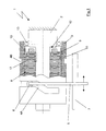
- Fig. 1 is a switching device 1 of a transmission of a motor vehicle with one on an axis 2 of the Switching device 1 rotatably guided switching element 3 shown.
- the switching element 3 is in the present embodiment provided with two groove tracks 4A, 4B, in which each engages a shift fork 5, wherein in Fig. 1st only one shift fork is shown. It goes without saying at the discretion of the person skilled in the art as a manual transmission trained switching element 3 depending on the particular Use case with more than two grooves.
- the shift fork 5 engages over a guide pin or a guide roller 6 in the groove track 4A and is itself at its end facing away from the guide pin 6 via a Shift fork guide 7 guided and displaceable in the axial direction stored.
- a Shift fork guide 7 guided and displaceable in the axial direction stored.
- a rotation of the shift drum 3 is with a Switching drum in operative connection electric motor 8 causes which comprises a stator 9 and a rotor 10.
- the Electric motor 8 or the stator-rotor unit is without its own Housing between the shift drum 3 and the axis 2, which is designed to be fixed to the transmission housing here.
- Switching device 1 forms the rotor 10 with the switching drum 3 such a structural unit that a rotational movement of the rotor 10 directly to the shift drum 3 becomes.
- the rotor 10 is formed by permanent magnets, which on the as a carrier for the permanent magnets provided shift drum 3 are glued. Of course it is at the discretion of the skilled person, the rotor 10 or whose permanent magnet by means of another, for the connection type suitable for the respective application Shift drum 3 to connect.
- the rotor 10 is closed with its entire cross section a magnetically active, flux-conducting component without a layered magnetic sheet or a typical electric motor material is necessary for this.
- Deviating from the embodiment shown in Fig. 1 can the shift drum of course also as a permanent magnet or formed from such a material be, so that an additional manufacturing step in the Manufacture of the switching device is omitted because of the attachment there is no permanent magnet on the shift drum.
- This configuration in which the rotor at the same time forms the shift drum, a further weight reduction of the transmission can be achieved.
- the stator 9, which according to the exemplary embodiment Fig. 1 is designed as a separate component, but in one alternative version also in one piece with axis 2 can be formed, includes a winding head as active elements and an iron yoke and has a symmetrical geometry with a substantially rectangular cross section on. Its outer contour is essentially cylindrical Form on and is attached to the rotor 10 surrounding it Electric motor 8 adapted. Next is between the rotor 10 and the stator 9, an air gap 11 is provided, which is parallel runs to a central axis of axis 2.
- connection 17 is provided.
- the non-rotatable connection 17 is in the present embodiment designed as a tongue and groove connection, the non-rotatable connection between the stator 9 and axis 2 of course also by another suitable one Connection type, such as a press fit or an adhesive can be carried out.
- the shift drum 3 is via a deep groove ball bearing 13 rotatably mounted on the axis 2 so that the shift drum 3rd on the one hand without or with only slight bearing friction losses Carry out rotary movements around their axis of rotation can.
- a circuit by the axial adjustment of the shift fork 5 to the Shift drum 3 acting axial forces from the shift drum 3 transferred to axis 2 in a simple manner become.
- the rotor 10 and the Shift drum 3 formed as two separate components, which are rotatably supported or guided on the axis 2.
- the Bearing of the rotor 10 is via a between the rotor 10 and the axis 3 arranged deep groove ball bearing 14 is formed.
- the shift drum 3 is also rotatable on the axis 2 stored, for this another between the rotor 10 and the shift drum 3 arranged deep groove ball bearing 15 is provided.
- the transmission gear 16 is in the present Embodiment not shown and can as a space-saving planetary gear as a simple one with two different sized gears Transmission gear or other suitable type and be designed as a translation device.
- the design or the dimensioning of the rotor 10 and the stator 9 is provided such that the required in the respective application Forces required for a rotary movement of the shift drum 3 be of the between the shift drum 3 and the Axle 2 arranged electric motor 8 are applied.
- the electric motor can be used as a DC or a AC motor are executed, the selection in Depends on the respective application.
- the Rotor can be dependent on the direction of rotation or independent of the direction of rotation be trained and direct and / or mechanical Translations be coupled to the shift drum.
- the rotor can be used as an external rotor as shown or designed as an inner runner his.
- the stator can be out of range between shift drum and axle to form a connection exit with a stationary component.
- the shift drum 3 a tube-like body, which already shows that the term “shift drum” is not to be understood geometrically is because it does not only include circular cylindrical bodies. Rather, the term “shift drum” is functional in view towards the rotation of the body labeled with it understand which different outside and inside contours can have.
Landscapes
- Engineering & Computer Science (AREA)
- General Engineering & Computer Science (AREA)
- Mechanical Engineering (AREA)
- Gear-Shifting Mechanisms (AREA)
Abstract
Description
Es zeigt:
- Fig. 1
- eine Schalteinrichtung eines Getriebes eines Kraftfahrzeuges mit einem zwischen einem Schaltelement und einer Achse integriertem Elektromotor und
- Fig. 2
- eine weitere Ausführungsform der Schalteinrichtung gemäß Fig. 1, wobei das Schaltelement und der Rotor als zwei getrennte Bauteile ausgebildet sind und zwischen diesen beiden ein Umsetzungsgetriebe zur Übertragung einer Drehbewegung vorgesehen ist.
- 1
- Schalteinrichtung
- 2
- Achse
- 3
- Schaltelement, Schaltwalze
- 4A, 4B
- Nutenbahn
- 5
- Schaltgabel
- 6
- Führungsstift
- 7
- Schaltgabelführung
- 8
- Elektromotor
- 9
- Stator
- 10
- Rotor
- 11
- Luftspalt
- 12
- Aufnehmung
- 13, 14, 15
- Rillenkugellager
- 16
- Übersetzungsgetriebe
- 17
- drehfeste Verbindung
Claims (8)
- Schalteinrichtung eines Getriebes mit einem auf einer Achse drehbar geführten, mit wenigstens einer Nutenbahn versehenen Schaltelement, wobei in die Nutenbahn wenigstens eine Schaltgabel eingreift, die bei einer Drehung des Schaltelementes durch die Form der Nutenbahn entsprechend axial bewegbar ist, wobei eine Drehung des Schaltelementes über einen mit dem Schaltelement in Wirkverbindung stehenden Elektromotor, der einen Stator und einen Rotor aufweist, durchführbar ist, dadurch gekennzeichnet , daß der Stator (9) und der Rotor (10) ohne eigenes Gehäuse wenigstens teilweise zwischen dem Schaltelement (3) und der Achse (2) angeordnet ist.
- Schalteinrichtung nach Anspruch 1, dadurch gekennzeichnet,daß der Rotor (10) und das Schaltelement (3) als zwei getrennte Bauteile ausgebildet sind und auf der gleichen Achse (2) drehbar geführt sind.
- Schalteinrichtung nach Anspruch 1 oder 2, dadurch gekennzeichnet, daß als Verbindung zwischen dem Schaltelement (3) und dem Rotor (10) zur Übertragung einer Drehbewegung des Rotors (10) auf das Schaltelement (3) ein Übersetzungsgetriebe (16) vorgesehen ist.
- Schalteinrichtung nach Anspruch 1, dadurch gekennzeichnet, daß der Rotor (10) mit dem Schaltelement (3) eine strukturelle Einheit ausbildet, wobei eine Drehbewegung des Rotors (10) direkt auf das Schaltelement (3) übertragbar ist.
- Schalteinrichtung nach Anspruch 4, dadurch gekennzeichnet, daß der Rotor (10) über das Schaltelement (3) um die Achse (2) drehbar geführt ist.
- Schalteinrichtung nach einem der Ansprüche 1 bis 5, dadurch gekennzeichnet, daß der Stator (9) an der Achse (2) angeordnet ist, wobei zwischen diesen eine drehfeste Verbindung (17) vorgesehen ist.
- Schalteinrichtung nach Anspruch 6, dadurch gekennzeichnet, daß eine sich wenigstens abschnittsweise über den Umfang der Achse (2) erstreckende Aufnehmung (12) vorgesehen ist, in welcher der Stator (9) wenigstens teilweise angeordnet ist.
- Schalteinrichtung nach einem der Ansprüche 1 bis 7, dadurch gekennzeichnet, daß das Schaltelement als rohrförmige Schaltwalze (3) ausgebildet ist.
Applications Claiming Priority (2)
| Application Number | Priority Date | Filing Date | Title |
|---|---|---|---|
| DE10051373 | 2000-10-17 | ||
| DE10051373A DE10051373A1 (de) | 2000-10-17 | 2000-10-17 | Schalteinrichtung eines Getriebes |
Publications (2)
| Publication Number | Publication Date |
|---|---|
| EP1199500A1 true EP1199500A1 (de) | 2002-04-24 |
| EP1199500B1 EP1199500B1 (de) | 2003-07-30 |
Family
ID=7660056
Family Applications (1)
| Application Number | Title | Priority Date | Filing Date |
|---|---|---|---|
| EP01124187A Expired - Lifetime EP1199500B1 (de) | 2000-10-17 | 2001-10-11 | Schalteinrichtung eines Getriebes |
Country Status (3)
| Country | Link |
|---|---|
| US (1) | US6725737B2 (de) |
| EP (1) | EP1199500B1 (de) |
| DE (2) | DE10051373A1 (de) |
Families Citing this family (13)
| Publication number | Priority date | Publication date | Assignee | Title |
|---|---|---|---|---|
| JP4673320B2 (ja) * | 2004-01-29 | 2011-04-20 | マグナ ドライブトレイン アクツィエン・ゲゼルシャフト ウント コンパニー コマンディート・ゲゼルシャフト | 移動自在なシフトフォーク部及びアクチュエータからなる変速装置 |
| US7467564B2 (en) * | 2006-03-13 | 2008-12-23 | Ford Global Technologies, Llc | Actuator mechanism for shift motors of a transmission |
| US7963183B2 (en) * | 2009-04-06 | 2011-06-21 | Dean Pick | Sequential transmission shift system |
| DE102011007264B4 (de) | 2011-04-13 | 2019-10-17 | Schaeffler Technologies AG & Co. KG | Schalteinrichtung mit einer Schaltwalze |
| FR3011052B1 (fr) * | 2013-09-23 | 2016-12-30 | Mijno Prec Gearing | Reducteur planetaire a double vitesse |
| CN105291827A (zh) * | 2015-11-19 | 2016-02-03 | 福建省福工动力技术有限公司 | 一种电动汽车驱动装置 |
| DE102017003865B4 (de) * | 2017-04-21 | 2025-12-18 | Lenze Se (Societas Europaea) | Elektrische Maschine |
| US10458523B2 (en) * | 2017-07-26 | 2019-10-29 | Hall Labs Llc | Automatic gear-shifting device |
| DE102018220503A1 (de) | 2018-11-28 | 2020-05-28 | Mahle International Gmbh | Parksperre und ein Getriebe mit der Parksperre |
| CN109973648A (zh) * | 2019-03-19 | 2019-07-05 | 西安法士特汽车传动有限公司 | 一种变速箱选档降阻机构及其选档方法 |
| EP3835626B1 (de) * | 2019-12-13 | 2024-04-24 | MEGA-Line RACING ELECTRONIC GmbH | Wechselgetriebe mit elektromotorisch angetriebener schaltwalze und verfahren zum wechseln zwischen mehreren übersetzungsstufen |
| DE102021104101A1 (de) | 2021-02-22 | 2022-08-25 | Mega-Line Racing Electronic Gmbh | Wechselgetriebe mit elektromotorisch angetriebener Schaltwalze sowie Verfahren zu dessen Steuerung |
| CN114050669A (zh) * | 2021-10-19 | 2022-02-15 | 凯博易控车辆科技(苏州)股份有限公司 | 一种外转子电机集成式换挡毂 |
Citations (4)
| Publication number | Priority date | Publication date | Assignee | Title |
|---|---|---|---|---|
| EP0481168A1 (de) * | 1990-07-21 | 1992-04-22 | INA Wälzlager Schaeffler KG | Schaltvorrichtung |
| EP0547007A1 (de) * | 1991-12-11 | 1993-06-16 | FIAT AUTO S.p.A. | Einrichtung zur Betätigung eines Kraftfahrzeuggetriebes |
| DE19645791A1 (de) * | 1996-11-07 | 1998-05-14 | Schaeffler Waelzlager Ohg | Spanlos hergestellte Schaltwalze für ein Zahnräderwechselgetriebe |
| DE19851738A1 (de) * | 1998-11-10 | 2000-05-18 | Getrag Getriebe Zahnrad | Triebstrang für ein Kraftfahrzeug |
Family Cites Families (9)
| Publication number | Priority date | Publication date | Assignee | Title |
|---|---|---|---|---|
| US4428248A (en) * | 1981-04-20 | 1984-01-31 | Eaton Corporation | Shifting actuator |
| US4449416A (en) * | 1981-09-04 | 1984-05-22 | J. I. Case Company | Transmission control system |
| DE4105157C2 (de) * | 1990-07-21 | 2003-05-15 | Ina Schaeffler Kg | Schaltvorrichtung |
| DE19530616C2 (de) * | 1995-08-21 | 1998-10-22 | Daimler Benz Ag | Schaltvorrichtung für Zahnräderwechselgetriebe |
| US5878624A (en) * | 1997-06-06 | 1999-03-09 | Borg-Warner Automotive, Inc. | Single rail shift operator assembly |
| DE19911274A1 (de) * | 1999-03-13 | 2000-09-21 | Bosch Gmbh Robert | Betätigungsvorrichtung für ein mehrgängiges Schaltgetriebe eines Kraftfahrzeuges |
| JP2000291796A (ja) * | 1999-04-05 | 2000-10-20 | Daihatsu Motor Co Ltd | 車両用変速機の自動シフト装置 |
| US6286381B1 (en) * | 1999-12-17 | 2001-09-11 | Daimlerchrysler Corporation | Gear preselect system for an electro-mechanical automatic transmission having dual input shafts |
| DE10136232A1 (de) * | 2001-07-25 | 2003-02-06 | Zahnradfabrik Friedrichshafen | Stellvorrichtung für ein automatisiertes Stufengetriebe eines Kraftfahrzeuges |
-
2000
- 2000-10-17 DE DE10051373A patent/DE10051373A1/de not_active Withdrawn
-
2001
- 2001-10-03 US US09/969,928 patent/US6725737B2/en not_active Expired - Fee Related
- 2001-10-11 EP EP01124187A patent/EP1199500B1/de not_active Expired - Lifetime
- 2001-10-11 DE DE50100433T patent/DE50100433D1/de not_active Expired - Lifetime
Patent Citations (4)
| Publication number | Priority date | Publication date | Assignee | Title |
|---|---|---|---|---|
| EP0481168A1 (de) * | 1990-07-21 | 1992-04-22 | INA Wälzlager Schaeffler KG | Schaltvorrichtung |
| EP0547007A1 (de) * | 1991-12-11 | 1993-06-16 | FIAT AUTO S.p.A. | Einrichtung zur Betätigung eines Kraftfahrzeuggetriebes |
| DE19645791A1 (de) * | 1996-11-07 | 1998-05-14 | Schaeffler Waelzlager Ohg | Spanlos hergestellte Schaltwalze für ein Zahnräderwechselgetriebe |
| DE19851738A1 (de) * | 1998-11-10 | 2000-05-18 | Getrag Getriebe Zahnrad | Triebstrang für ein Kraftfahrzeug |
Also Published As
| Publication number | Publication date |
|---|---|
| EP1199500B1 (de) | 2003-07-30 |
| DE50100433D1 (de) | 2003-09-04 |
| US6725737B2 (en) | 2004-04-27 |
| US20020062706A1 (en) | 2002-05-30 |
| DE10051373A1 (de) | 2002-04-18 |
Similar Documents
| Publication | Publication Date | Title |
|---|---|---|
| DE3416938C2 (de) | Von einem Elektromotor angetriebenes, eine Längsbewegung ausführendes Stellglied | |
| DE69500194T2 (de) | Stellantrieb zum Lenken der Hinterräder | |
| AT408210B (de) | Elektrischer antrieb für ein fahrzeug | |
| AT405924B (de) | Antrieb für ein fahrzeug, insbesondere für ein mehrspuriges elektromobil | |
| EP1199500B1 (de) | Schalteinrichtung eines Getriebes | |
| EP1999399B1 (de) | Aktuatoranordnung und schaltkupplungsanordnung | |
| EP0757193A1 (de) | Elektrische Schaltvorrichtung für Wechselgetriebe von Kraftfahrzeugen | |
| EP1301977A2 (de) | Rotorbaugruppe für einen elektromotor und innenläufer-elektromotor | |
| DE102018110151A1 (de) | Elektrische Maschine mit Elektromotor und Magnetgetriebe | |
| DE102017205666A1 (de) | Lenkung mit einer Stelleinrichtung sowie Verwendung der Lenkung mit Stelleinrichtung | |
| EP1332300B1 (de) | Elektromechanisch betätigbare scheibenbremse | |
| EP0481168A1 (de) | Schaltvorrichtung | |
| DE102019205978A1 (de) | Elektromechanischer Bremsdruckerzeuger für ein hydraulisches Bremssystem eines Fahrzeugs | |
| DE102023205772A1 (de) | Antriebsstrang für ein wenigstens teilweise elektrisch angetriebenes Fahrrad | |
| EP1203895A2 (de) | Elektromechanisch betätigbare Scheibenbremse mit einer Feststellbremsanlage | |
| EP1108584B1 (de) | Radantriebsvorrichtung | |
| WO1998012097A1 (de) | Elektrisch unterstützte lenkhilfe | |
| EP1048401A2 (de) | Werkzeugwechselvorrichtung | |
| DE10310777A1 (de) | Elektromaschine mit koaxialen, mehrfach abwechselnden Magnet- und Wicklungslagen | |
| DE202018103172U1 (de) | Motoranordnung | |
| DE102008041335A1 (de) | Lenkgetriebe und damit ausgestattete Servolenkung | |
| DE102005025266A1 (de) | Aktor zur Betätigung einer Doppelkupplung | |
| AT523723B1 (de) | Getriebemotor | |
| EP0875982A1 (de) | Elektromagnetischer Linearantrieb | |
| DE102023109266B4 (de) | Lenkungsaktuator und Verfahren zum Betrieb einer Hinterachslenkung |
Legal Events
| Date | Code | Title | Description |
|---|---|---|---|
| PUAI | Public reference made under article 153(3) epc to a published international application that has entered the european phase |
Free format text: ORIGINAL CODE: 0009012 |
|
| 17P | Request for examination filed |
Effective date: 20011222 |
|
| AK | Designated contracting states |
Kind code of ref document: A1 Designated state(s): DE FR GB Kind code of ref document: A1 Designated state(s): AT BE CH CY DE DK ES FI FR GB GR IE IT LI LU MC NL PT SE TR |
|
| AX | Request for extension of the european patent |
Free format text: AL;LT;LV;MK;RO;SI |
|
| AKX | Designation fees paid |
Free format text: DE FR GB |
|
| GRAH | Despatch of communication of intention to grant a patent |
Free format text: ORIGINAL CODE: EPIDOS IGRA |
|
| GRAH | Despatch of communication of intention to grant a patent |
Free format text: ORIGINAL CODE: EPIDOS IGRA |
|
| GRAA | (expected) grant |
Free format text: ORIGINAL CODE: 0009210 |
|
| AK | Designated contracting states |
Designated state(s): DE FR GB |
|
| REG | Reference to a national code |
Ref country code: GB Ref legal event code: FG4D Free format text: NOT ENGLISH |
|
| REG | Reference to a national code |
Ref country code: IE Ref legal event code: FG4D Free format text: GERMAN |
|
| REF | Corresponds to: |
Ref document number: 50100433 Country of ref document: DE Date of ref document: 20030904 Kind code of ref document: P |
|
| GBT | Gb: translation of ep patent filed (gb section 77(6)(a)/1977) | ||
| ET | Fr: translation filed | ||
| REG | Reference to a national code |
Ref country code: IE Ref legal event code: FD4D |
|
| PLBE | No opposition filed within time limit |
Free format text: ORIGINAL CODE: 0009261 |
|
| STAA | Information on the status of an ep patent application or granted ep patent |
Free format text: STATUS: NO OPPOSITION FILED WITHIN TIME LIMIT |
|
| 26N | No opposition filed |
Effective date: 20040504 |
|
| PGFP | Annual fee paid to national office [announced via postgrant information from national office to epo] |
Ref country code: GB Payment date: 20131009 Year of fee payment: 13 Ref country code: FR Payment date: 20131009 Year of fee payment: 13 |
|
| GBPC | Gb: european patent ceased through non-payment of renewal fee |
Effective date: 20141011 |
|
| PG25 | Lapsed in a contracting state [announced via postgrant information from national office to epo] |
Ref country code: GB Free format text: LAPSE BECAUSE OF NON-PAYMENT OF DUE FEES Effective date: 20141011 |
|
| REG | Reference to a national code |
Ref country code: FR Ref legal event code: ST Effective date: 20150630 |
|
| PG25 | Lapsed in a contracting state [announced via postgrant information from national office to epo] |
Ref country code: FR Free format text: LAPSE BECAUSE OF NON-PAYMENT OF DUE FEES Effective date: 20141031 |
|
| PGFP | Annual fee paid to national office [announced via postgrant information from national office to epo] |
Ref country code: DE Payment date: 20161004 Year of fee payment: 16 |
|
| REG | Reference to a national code |
Ref country code: DE Ref legal event code: R119 Ref document number: 50100433 Country of ref document: DE |
|
| PG25 | Lapsed in a contracting state [announced via postgrant information from national office to epo] |
Ref country code: DE Free format text: LAPSE BECAUSE OF NON-PAYMENT OF DUE FEES Effective date: 20180501 |