EP1199486B1 - Hydrodynamisches Axiallager mit Schwimmscheibe - Google Patents
Hydrodynamisches Axiallager mit Schwimmscheibe Download PDFInfo
- Publication number
- EP1199486B1 EP1199486B1 EP00810959A EP00810959A EP1199486B1 EP 1199486 B1 EP1199486 B1 EP 1199486B1 EP 00810959 A EP00810959 A EP 00810959A EP 00810959 A EP00810959 A EP 00810959A EP 1199486 B1 EP1199486 B1 EP 1199486B1
- Authority
- EP
- European Patent Office
- Prior art keywords
- bearing
- radial
- bearing element
- hydrodynamic axial
- hydrodynamic
- Prior art date
- Legal status (The legal status is an assumption and is not a legal conclusion. Google has not performed a legal analysis and makes no representation as to the accuracy of the status listed.)
- Expired - Lifetime
Links
- 239000010687 lubricating oil Substances 0.000 claims description 42
- 208000008103 Amniotic Band Syndrome Diseases 0.000 claims 3
- 239000003921 oil Substances 0.000 description 6
- 238000005461 lubrication Methods 0.000 description 5
- 238000004519 manufacturing process Methods 0.000 description 3
- 230000009182 swimming Effects 0.000 description 3
- 229910000831 Steel Inorganic materials 0.000 description 2
- 238000005266 casting Methods 0.000 description 2
- 238000002485 combustion reaction Methods 0.000 description 2
- 239000007787 solid Substances 0.000 description 2
- 239000010959 steel Substances 0.000 description 2
- 238000004381 surface treatment Methods 0.000 description 2
- 230000005540 biological transmission Effects 0.000 description 1
- 230000015572 biosynthetic process Effects 0.000 description 1
- 239000011248 coating agent Substances 0.000 description 1
- 238000000576 coating method Methods 0.000 description 1
- 150000001875 compounds Chemical class 0.000 description 1
- 238000010276 construction Methods 0.000 description 1
- 230000001419 dependent effect Effects 0.000 description 1
- 230000000694 effects Effects 0.000 description 1
- 239000004519 grease Substances 0.000 description 1
- 230000001050 lubricating effect Effects 0.000 description 1
- 239000000463 material Substances 0.000 description 1
- 230000000149 penetrating effect Effects 0.000 description 1
- 230000035939 shock Effects 0.000 description 1
- 238000003860 storage Methods 0.000 description 1
- 238000003466 welding Methods 0.000 description 1
Images



Classifications
-
- F—MECHANICAL ENGINEERING; LIGHTING; HEATING; WEAPONS; BLASTING
- F16—ENGINEERING ELEMENTS AND UNITS; GENERAL MEASURES FOR PRODUCING AND MAINTAINING EFFECTIVE FUNCTIONING OF MACHINES OR INSTALLATIONS; THERMAL INSULATION IN GENERAL
- F16C—SHAFTS; FLEXIBLE SHAFTS; ELEMENTS OR CRANKSHAFT MECHANISMS; ROTARY BODIES OTHER THAN GEARING ELEMENTS; BEARINGS
- F16C17/00—Sliding-contact bearings for exclusively rotary movement
- F16C17/10—Sliding-contact bearings for exclusively rotary movement for both radial and axial load
-
- F—MECHANICAL ENGINEERING; LIGHTING; HEATING; WEAPONS; BLASTING
- F16—ENGINEERING ELEMENTS AND UNITS; GENERAL MEASURES FOR PRODUCING AND MAINTAINING EFFECTIVE FUNCTIONING OF MACHINES OR INSTALLATIONS; THERMAL INSULATION IN GENERAL
- F16C—SHAFTS; FLEXIBLE SHAFTS; ELEMENTS OR CRANKSHAFT MECHANISMS; ROTARY BODIES OTHER THAN GEARING ELEMENTS; BEARINGS
- F16C33/00—Parts of bearings; Special methods for making bearings or parts thereof
- F16C33/02—Parts of sliding-contact bearings
- F16C33/04—Brasses; Bushes; Linings
- F16C33/06—Sliding surface mainly made of metal
- F16C33/10—Construction relative to lubrication
- F16C33/1025—Construction relative to lubrication with liquid, e.g. oil, as lubricant
- F16C33/106—Details of distribution or circulation inside the bearings, e.g. details of the bearing surfaces to affect flow or pressure of the liquid
- F16C33/1075—Wedges, e.g. ramps or lobes, for generating pressure
-
- F—MECHANICAL ENGINEERING; LIGHTING; HEATING; WEAPONS; BLASTING
- F01—MACHINES OR ENGINES IN GENERAL; ENGINE PLANTS IN GENERAL; STEAM ENGINES
- F01D—NON-POSITIVE DISPLACEMENT MACHINES OR ENGINES, e.g. STEAM TURBINES
- F01D25/00—Component parts, details, or accessories, not provided for in, or of interest apart from, other groups
- F01D25/16—Arrangement of bearings; Supporting or mounting bearings in casings
- F01D25/166—Sliding contact bearing
- F01D25/168—Sliding contact bearing for axial load mainly
-
- F—MECHANICAL ENGINEERING; LIGHTING; HEATING; WEAPONS; BLASTING
- F04—POSITIVE - DISPLACEMENT MACHINES FOR LIQUIDS; PUMPS FOR LIQUIDS OR ELASTIC FLUIDS
- F04D—NON-POSITIVE-DISPLACEMENT PUMPS
- F04D29/00—Details, component parts, or accessories
- F04D29/04—Shafts or bearings, or assemblies thereof
- F04D29/041—Axial thrust balancing
- F04D29/0413—Axial thrust balancing hydrostatic; hydrodynamic thrust bearings
-
- F—MECHANICAL ENGINEERING; LIGHTING; HEATING; WEAPONS; BLASTING
- F16—ENGINEERING ELEMENTS AND UNITS; GENERAL MEASURES FOR PRODUCING AND MAINTAINING EFFECTIVE FUNCTIONING OF MACHINES OR INSTALLATIONS; THERMAL INSULATION IN GENERAL
- F16C—SHAFTS; FLEXIBLE SHAFTS; ELEMENTS OR CRANKSHAFT MECHANISMS; ROTARY BODIES OTHER THAN GEARING ELEMENTS; BEARINGS
- F16C17/00—Sliding-contact bearings for exclusively rotary movement
- F16C17/04—Sliding-contact bearings for exclusively rotary movement for axial load only
-
- F—MECHANICAL ENGINEERING; LIGHTING; HEATING; WEAPONS; BLASTING
- F16—ENGINEERING ELEMENTS AND UNITS; GENERAL MEASURES FOR PRODUCING AND MAINTAINING EFFECTIVE FUNCTIONING OF MACHINES OR INSTALLATIONS; THERMAL INSULATION IN GENERAL
- F16C—SHAFTS; FLEXIBLE SHAFTS; ELEMENTS OR CRANKSHAFT MECHANISMS; ROTARY BODIES OTHER THAN GEARING ELEMENTS; BEARINGS
- F16C17/00—Sliding-contact bearings for exclusively rotary movement
- F16C17/12—Sliding-contact bearings for exclusively rotary movement characterised by features not related to the direction of the load
- F16C17/18—Sliding-contact bearings for exclusively rotary movement characterised by features not related to the direction of the load with floating brasses or brushing, rotatable at a reduced speed
-
- F—MECHANICAL ENGINEERING; LIGHTING; HEATING; WEAPONS; BLASTING
- F16—ENGINEERING ELEMENTS AND UNITS; GENERAL MEASURES FOR PRODUCING AND MAINTAINING EFFECTIVE FUNCTIONING OF MACHINES OR INSTALLATIONS; THERMAL INSULATION IN GENERAL
- F16C—SHAFTS; FLEXIBLE SHAFTS; ELEMENTS OR CRANKSHAFT MECHANISMS; ROTARY BODIES OTHER THAN GEARING ELEMENTS; BEARINGS
- F16C33/00—Parts of bearings; Special methods for making bearings or parts thereof
- F16C33/02—Parts of sliding-contact bearings
- F16C33/04—Brasses; Bushes; Linings
- F16C33/06—Sliding surface mainly made of metal
- F16C33/10—Construction relative to lubrication
- F16C33/1025—Construction relative to lubrication with liquid, e.g. oil, as lubricant
- F16C33/106—Details of distribution or circulation inside the bearings, e.g. details of the bearing surfaces to affect flow or pressure of the liquid
-
- F—MECHANICAL ENGINEERING; LIGHTING; HEATING; WEAPONS; BLASTING
- F05—INDEXING SCHEMES RELATING TO ENGINES OR PUMPS IN VARIOUS SUBCLASSES OF CLASSES F01-F04
- F05D—INDEXING SCHEME FOR ASPECTS RELATING TO NON-POSITIVE-DISPLACEMENT MACHINES OR ENGINES, GAS-TURBINES OR JET-PROPULSION PLANTS
- F05D2220/00—Application
- F05D2220/40—Application in turbochargers
-
- F—MECHANICAL ENGINEERING; LIGHTING; HEATING; WEAPONS; BLASTING
- F05—INDEXING SCHEMES RELATING TO ENGINES OR PUMPS IN VARIOUS SUBCLASSES OF CLASSES F01-F04
- F05D—INDEXING SCHEME FOR ASPECTS RELATING TO NON-POSITIVE-DISPLACEMENT MACHINES OR ENGINES, GAS-TURBINES OR JET-PROPULSION PLANTS
- F05D2240/00—Components
- F05D2240/50—Bearings
- F05D2240/52—Axial thrust bearings
-
- F—MECHANICAL ENGINEERING; LIGHTING; HEATING; WEAPONS; BLASTING
- F05—INDEXING SCHEMES RELATING TO ENGINES OR PUMPS IN VARIOUS SUBCLASSES OF CLASSES F01-F04
- F05D—INDEXING SCHEME FOR ASPECTS RELATING TO NON-POSITIVE-DISPLACEMENT MACHINES OR ENGINES, GAS-TURBINES OR JET-PROPULSION PLANTS
- F05D2240/00—Components
- F05D2240/50—Bearings
- F05D2240/53—Hydrodynamic or hydrostatic bearings
-
- F—MECHANICAL ENGINEERING; LIGHTING; HEATING; WEAPONS; BLASTING
- F16—ENGINEERING ELEMENTS AND UNITS; GENERAL MEASURES FOR PRODUCING AND MAINTAINING EFFECTIVE FUNCTIONING OF MACHINES OR INSTALLATIONS; THERMAL INSULATION IN GENERAL
- F16C—SHAFTS; FLEXIBLE SHAFTS; ELEMENTS OR CRANKSHAFT MECHANISMS; ROTARY BODIES OTHER THAN GEARING ELEMENTS; BEARINGS
- F16C2360/00—Engines or pumps
- F16C2360/23—Gas turbine engines
- F16C2360/24—Turbochargers
Definitions
- the invention relates to a hydrodynamic axial bearing with floating disk according the preamble of claim 1.
- the skewing compensation capability and to improve the wear behavior can be between the rotating with shaft speed bearing comb and the non-rotating Housing so-called floating discs be used.
- floating discs find examples inter alia in US-1,786,565 and GB-1,095,999.
- the Radial Leadership of Floating disc takes place on the rotating body, i. on the shaft or on the bearing comb by a built-in floating disc radial bearing, as it For example, in DE-A-196 41 673 is disclosed.
- the lubrication of such a hydrodynamic Axial bearings usually takes place by means of lubricating oil from its own Lubricating oil system or turbochargers via the lubricating oil system one with the Turbocharger connected internal combustion engine.
- Object of the present invention is therefore a hydrodynamic thrust bearing to provide with floating disk, in which an overload of the radial bearing the swimming disk is largely excluded.
- bearing element and bearing body can be advantageous if the bearing body, e.g. is manufactured as a casting and the bearing element a high wear resistance by special material choice or Surface treatment should receive.
- the bearing element has a press fit held a press fit fitting for the press fit on. It is particularly advantageous to provide the fitting part with a recess. In this way, the bearing element can be easily fitted in the press fit, and it may be the deformation of the bearing element in the region of the bearing seat - caused by the interference fit - be kept low.
- the recess can be very cheap at the same time as a lubricating oil reservoir for the lubrication of the floating disk be used.
- the decoupling gap between the bearing element and the rotating body can with Advantage be designed as a wide tolerance gap. Penetrating into the decoupling gap Lubricating oil can then not reduce the decoupling properties.
- the bearing element can be configured such that via the bearing element Lubricating oil into the radial bearing of the floating disk and surrounding them Grease column passes.
- the bearing element with a lubricating oil supply in conductive connection be brought and the cooperating with the floating disk surface of the bearing body can be profiled in such a way that via this profile one for the Lubricating oil permeable connection between the oil gaps exists.
- One such profile may be designed to function as a hydrodynamic radial bearing works for the floating disc and the floating disc itself no integrated Radial bearing must have.
- connection openings which in the Radial bearing and the lubrication gaps open and in conjunction with a lubricating oil supply stand so that the lubricating oil directly into the lubricating oil column and the radial bearing can be fed.
- connection openings can additionally provided to the profile or without a profile on the outside of the bearing element be.
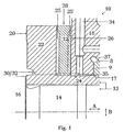
- FIG. 1 shows a hydrodynamic thrust bearing 10 with a floating disk 12 according to the prior art, as e.g. used in a turbocharger.
- the Thrust bearing 10 includes a bearing body 18 in which a radial bearing 17 for radial Storage of a rotating body 13 is formed.
- the radial bearing 17 is through a radial bearing element 9 realized in a radial bearing recess 8 of the bearing body 18 is fitted.
- the rotating body 13 includes in this example a shaft 16 with a bearing pin 14 and a bearing comb 20.
- the bearing comb 20 has a vertically projecting from the shaft 16 radially outward, circular-shaped projection 22 and a bearing pin 14 comprehensive and extending in the axial direction (A) part 24.
- the bearing pin 14 and the Bearing comb 20 are firmly connected together, e.g. by means of interference fit, so that the bearing comb 20 at the same speed with the shaft 16 co-rotated.
- Bearing pin 14 and part 24 of the bearing comb 20 extend into the radial bearing 17 and are absorbed by this.
- the projection 22 of the bearing comb 20 is located outside of the radial bearing 17 and forms together with a wall 26 of the bearing body 18 a ringnutenförmigen Room 28.
- the floating disk 12 is arranged.
- the Room 28 and the floating disk 12 are dimensioned so that between the Floating disk 12 and the wall 26 and between the floating disk 12 and the projection 22 lubricating oil gaps 25, 25 'are present.
- the swimming disk 12 and the wall 26 and the projection 22 are limiting to the respective Lubricating oil gap 25, 25 'profiled in such a way that the arrangement in operation with the in The ring groove-shaped space 28 fed lubricating oil a hydrodynamic Thrust bearing forms.
- the floating disk 12 has a central circular opening 30, with which it is mounted radially on the rotating body 13.
- the central circular opening 30 is formed as a hydrodynamic radial bearing 32 of the floating disk 12 and forms in operation with the injected into the annular groove 28 space Lubricating oil from a lubricating oil film lubricating the radial bearing 32.
- Via the profiled circular opening 30 is also the lubricating oil supply of between Floating disc 12 and projection 22 formed lubricating oil gap 25 'guaranteed.
- An example of such a profiling of the floating disk 12 and the space 28 limiting elements 22, 26 and for the formation of the radial bearing is described in DE-A-196 41 673.
- the lubricating oil is from its own lubricating oil system or, for example a turbocharger from the lubricating oil system of a connected to the turbocharger Internal combustion engine, supplied (not shown).
- the supply takes place in a known Way e.g. via a radial feed channel 34, which at its radially inward lying end connected by an annular channel 35 with the annular groove space 28 is.
- the radial bearing 17 is supplied with lubricating oil, via an oil passage 37 is discharged.
- For large radial vibrations (arrow B) of the rotating Body 13 may overload the lubricating oil film Floating disc 12 and rotating body 13 come. Wear or even accident of the camp are the result.
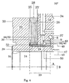
- FIGS 2 to 5 show various embodiments of the inventive hydrodynamic thrust bearing 10 ', 10 ", 10' '', 10" ", with a basic construction of the known from Fig. 1 thrust bearing 10 corresponds.
- thrust bearing 10 is in Figures 2 to 5, the floating disk 12 with her central circular opening 30 instead of on the rotating body 13 on a fixed Bearing element 38 radially mounted.
- the bearing body 18 manufactured as a casting; the bearing element 38 is made of steel and with a wear-resistant coating or surface treatment provided.
- the Bearing element 38 is fixedly connected to the bearing body 18 and has a cylindrical, in the axial direction (A) extending bearing part 39 and a substantially circular disk-shaped fitting part 40, which with respect to the axial direction (A) perpendicular, radially outwardly from the bearing part 39 protrudes.
- Das Bearing part 39 of the bearing element 38 extends from the fitting part 40 axially through the ring groove-shaped space 28 to the projection 22 of the bearing block 20.
- the bearing element 38 concentrically surrounds the rotating part on a section 29 Body 13 of the thrust bearing 10 and forms with this in section 29 a decoupling gap 50th
- the bearing element 38 is formed as a closed sleeve 36 and the Decoupling gap 50 as air or oil filled tolerance gap.
- the lubrication between Floating disc 12 and bearing element 38 by means of lubricating oil, the ring groove-shaped space 28 via radial feed channel 34 and connected to this Ring channel 35 is supplied.
- the integrated into the floating disk 12 Radial bearing 32 is designed so that it the lubricating oil passage in the lubricating oil gap 25 between floating disk 12 and projection 22 allows.
- the hydrodynamic thrust bearing 10 "shown in FIG. 3 has the same design as FIG the thrust bearing 10 'shown in Figure 2.
- the radial bearing of the floating disk 12 again takes place on a fixed bearing element 38.
- the annular recess 48 connected to the feed channel 34 and the annular channel 35 and serves at the same time as a lubricating oil reservoir for oil lubrication in the annular groove 28 space.
- the Floating disc 12 facing outside 44 of the bearing part 39 of the bearing element 38 formed as a radial bearing 32. Via the profiled outer side 44 of the bearing part 39 is also the lubricating oil supply between the floating disk 12 and Projection 22 trained lubricating oil gap 25 'guaranteed.
- the thrust bearing 10 '' 'in Fig. 4 is the same structure as the thrust bearing shown in Fig. 3 10 ".
- the lubricating oil supply the radial bearing 32 of the floating disk 12 and the Lubricating oil gaps 25, 25 ' is ensured by connecting openings 52, which in Bearing part 39 of the bearing element 38 are provided and the annular groove-shaped Connect space 28 to the lubricating oil feed passage 34.
- FIG. 5 shows a thrust bearing 10 "" which is constructed analogously to the thrust bearing 10 'from FIG is. It differs only in that the bearing element 38 and the bearing body 18 in one piece, in this example made of steel, are formed. Of course you can also the embodiments shown in Figures 3 and 4 in the form of one piece be formed with the bearing body 18 connected bearing elements 38.
- connection openings 52 can be added be provided to the lubricating oil supply shown in Figs. 2 to 4.
- the rotating one Body 13 of the hydrodynamic thrust bearing 10 ', 10 “, 10' '', 10” ", for example on the portion 29 only from the shaft 16 and the shaft journal 14th consist.
- the bearing comb 20 with its part 24 and the Projection 22 may be provided other elements co-rotating with the shaft 16.
- the Projection 22 of the bearing block 20 may also be provided without the axial part 24 be.
- the projection 22 may also be integral with the shaft 16 and the shaft journal 14 be formed.
- the bearing element 38 may, for example, without radial outwardly projecting fitting part, be designed rather tubular and means a simple shrink fit to be firmly connected to the bearing body 18. Other compounds, such as e.g. Welding is conceivable.
- the bearing element 38 can also take place with the bearing body 18 with another fixed element, such as. a housing part, to be firmly connected.
- a recess 48 as Lubricating oil reservoir may also be provided, if not for a press fit is needed.
- the hydrodynamic thrust bearing 10 prevents the decoupling gap 50 between the rotating body 13 and the fixed bearing element 38, the transmission of radial vibrations (arrow B) of the rotating body 13 on the radial bearing 32 of the floating disk 12. Die Floating disc 12 and its radial bearing 32 are not affected by the vibrations loaded and wear or even a failure of the camp are prevented.
Landscapes
- Engineering & Computer Science (AREA)
- General Engineering & Computer Science (AREA)
- Mechanical Engineering (AREA)
- Chemical & Material Sciences (AREA)
- Oil, Petroleum & Natural Gas (AREA)
- Physics & Mathematics (AREA)
- Fluid Mechanics (AREA)
- Sliding-Contact Bearings (AREA)
Description
- Fig.: 1
- Ein hydrodynamisches Axiallager mit Schwimmscheibe gemäss Stand der Technik im Schnitt entlang der Längsachse des rotierenden Körpers des Axiallagers; und
- Fig.: 2 bis 5
- verschiedene Ausführungsformen des erfindungsgemässen hydrodynamischen Axiallagers mit Schwimmscheibe im Schnitt entlang der Längsachse des rotierenden Körpers des Axiallagers.
- 8
- Radiallagerausnehmung
- 9
- Radiallagerelement
- 10 bis 10""
- Hydrodynamisches Axiallager
- 12
- Schwimmscheibe
- 13
- rotierender Körper
- 14
- Lagerzapfen
- 16
- Welle
- 17
- Radiallager
- 18
- Lagerkörper
- 20
- Lagerkamm
- 22
- Vorsprung
- 24
- Teil des Lagerkammes
- 25, 25'
- Schmierölspalt
- 26
- Wand
- 28
- ringnutenförmiger Raum
- 29
- Abschnitt
- 30
- zentrale Kreisöffnung
- 32
- Radiallager
- 34
- Zuführkanal
- 35
- Ringkanal
- 36
- Büchse
- 37
- Ölkanal
- 38
- Lagerelement
- 39
- Lagerteil
- 40
- Passteil
- 42
- Nut
- 44
- Aussenseite
- 48
- Ausnehmung
- 50
- Entkopplungsspalt
- 52
- Öffnung
Claims (9)
- Hydrodynamisches Axiallager mit einem Lagerkörper (18), einem in einem Radiallager (17) des Lagerkörpers (18) gelagerten rotierenden Körper (13), der einen mitrotierenden Vorsprung (22) aufweist, und mit einer Schwimmscheibe (12), die in einem ringnutenförmigen Raum (28) zwischen dem Vorsprung (22) und einer Wand (26) des feststehenden Lagerkörpers (18) angeordnet und radial via ein hydrodynamisches Radiallager (32) gelagert ist, dadurch gekennzeichnet, dass die Schwimmscheibe (12) radial auf einem feststehenden Lagerelement (38) gelagert ist, welches den rotierenden Körper (13) auf einem Abschnitt (29) konzentrisch umgibt, so dass zwischen dem feststehenden Lagerelement (38) und dem rotierenden Körper (13) im Abschnitt (29) ein Entkopplungsspalt (50) gebildet ist.
- Hydrodynamisches Axiallager nach Anspruch 1, dadurch gekennzeichnet, dass das Lagerelement (38) einstückig mit dem Lagerkörper (18) ausgestaltet ist.
- Hydrodynamisches Axiallager nach Anspruch 1, dadurch gekennzeichnet, dass das Lagerelement (38) und Lagerkörper (18) separate Teile sind und das Lagerelement (38) mit dem Lagerkörper (18) fest verbunden ist und zwar vorzugsweise via eine Presspassung.
- Hydrodynamisches Axiallager nach Anspruch 3, dadurch gekennzeichnet, dass das Lagerelement (38) ein in einen Presssitz passendes Passteil 40 aufweist, in dem insbesondere eine Ausnehmung (48) vorgesehen ist, die vorzugsweise auch als Schmierölreservoir dient.
- Hydrodynamisches Axiallager nach einem der Ansprüche 1 bis 4, dadurch gekennzeichnet, dass das Lagerelement (38) eine geschlossene Büchse (36) ist.
- Hydrodynamisches Axiallager nach einem der Ansprüche 1 bis 5, dadurch gekennzeichnet, dass der Entkopplungsspalt (50) ein luftgefüllter Toleranzspalt ist.
- Hydrodynamisches Axiallager nach einem der Ansprüche 1 bis 4, dadurch gekennzeichnet, dass der ringnutenförmige Raum (28) und die in ihm angeordneten Schmierölspalten (25, 25') sowie das Radiallager (32) via das Lagerelement (38) mit der Schmierölzuführung (34) verbunden ist.
- Hydrodynamisches Axiallager nach Anspruch 7, dadurch gekennzeichnet, dass die beiden Schmierölspalten (25, 25') via ein geeignetes Profil auf der der Schwimmscheibe (12) zugewandten Aussenseite (44) eines Lagerteils (39) des Lagerelementes (38) miteinander verbunden ist.
- Hydrodynamisches Axiallager nach Anspruch 7 oder 8, dadurch gekennzeichnet, dass der ringnutenförmige Raum (28), die Schmierölspalten (25, 25') und das Radiallager (32) via Verbindungsöffnungen (52) im Lagerelement 38 mit der Schmierölzuführung (34) verbunden sind.
Priority Applications (6)
| Application Number | Priority Date | Filing Date | Title |
|---|---|---|---|
| EP00810959A EP1199486B1 (de) | 2000-10-17 | 2000-10-17 | Hydrodynamisches Axiallager mit Schwimmscheibe |
| DE50009877T DE50009877D1 (de) | 2000-10-17 | 2000-10-17 | Hydrodynamisches Axiallager mit Schwimmscheibe |
| US09/972,921 US6585418B2 (en) | 2000-10-17 | 2001-10-10 | Hydrodynamic axial bearing with floating disk |
| KR1020010063329A KR100828473B1 (ko) | 2000-10-17 | 2001-10-15 | 부동디스크를 갖춘 유체역학적 축베어링 |
| JP2001319817A JP4090719B2 (ja) | 2000-10-17 | 2001-10-17 | フローティングディスクを有するハイドロダイナミック式のアキシャル軸受 |
| CN011357754A CN1218131C (zh) | 2000-10-17 | 2001-10-17 | 具有浮动盘的液力轴向轴承 |
Applications Claiming Priority (1)
| Application Number | Priority Date | Filing Date | Title |
|---|---|---|---|
| EP00810959A EP1199486B1 (de) | 2000-10-17 | 2000-10-17 | Hydrodynamisches Axiallager mit Schwimmscheibe |
Publications (2)
| Publication Number | Publication Date |
|---|---|
| EP1199486A1 EP1199486A1 (de) | 2002-04-24 |
| EP1199486B1 true EP1199486B1 (de) | 2005-03-23 |
Family
ID=8174974
Family Applications (1)
| Application Number | Title | Priority Date | Filing Date |
|---|---|---|---|
| EP00810959A Expired - Lifetime EP1199486B1 (de) | 2000-10-17 | 2000-10-17 | Hydrodynamisches Axiallager mit Schwimmscheibe |
Country Status (6)
| Country | Link |
|---|---|
| US (1) | US6585418B2 (de) |
| EP (1) | EP1199486B1 (de) |
| JP (1) | JP4090719B2 (de) |
| KR (1) | KR100828473B1 (de) |
| CN (1) | CN1218131C (de) |
| DE (1) | DE50009877D1 (de) |
Cited By (1)
| Publication number | Priority date | Publication date | Assignee | Title |
|---|---|---|---|---|
| US8021105B2 (en) | 2007-09-26 | 2011-09-20 | Abb Turbo Systems Ag | Hydrodynamic axial bearing |
Families Citing this family (7)
| Publication number | Priority date | Publication date | Assignee | Title |
|---|---|---|---|---|
| US7631513B2 (en) * | 2005-03-25 | 2009-12-15 | Lg Electronics Inc. | Ice bank of refrigerator |
| US10092169B2 (en) | 2008-07-08 | 2018-10-09 | Karl Storz Imaging, Inc. | Solid state variable direction of view endoscope |
| DE102011013830A1 (de) * | 2011-03-11 | 2012-08-02 | Ruhrpumpen Gmbh | Hydrodynamisches Gleitlager, insbesondere einer Magnetkupplungspumpe |
| DE102011085681A1 (de) | 2011-11-03 | 2013-05-08 | Abb Turbo Systems Ag | Hydrodynamisches Axiallager |
| EP2669537A1 (de) | 2012-06-01 | 2013-12-04 | Alstom Technology Ltd. | Radiales Segmentlager für Turbine |
| CN106321637B (zh) * | 2016-11-08 | 2019-03-26 | 哈尔滨广瀚动力传动有限公司 | 一种应用于双向旋转大比压高速行星轮轴承 |
| DE102020114268A1 (de) | 2020-05-28 | 2021-12-02 | Man Energy Solutions Se | Axiallager für einen Axialturbolader |
Family Cites Families (23)
| Publication number | Priority date | Publication date | Assignee | Title |
|---|---|---|---|---|
| DE49087C (de) | A. V. WVRSTBMberger & CO. in Zürich, Sihl-Str. 43, und J. schweizer in Zürich, Weinberg-Str. 23 | Petroleum-Retortenbrenner. (2 | ||
| US1786565A (en) | 1927-10-18 | 1930-12-30 | American Telephone & Telegraph | Thrust bearing |
| GB1095999A (en) * | 1964-05-28 | 1967-12-20 | Hawker Siddeley Canada Ltd | Improvements in fluid thrust bearing |
| DE3132443A1 (de) * | 1981-08-17 | 1983-02-24 | Skf Kugellagerfabriken Gmbh, 8720 Schweinfurt | Anordnung zur axialen festlegung von maschinenelementen |
| JPS5887935U (ja) | 1981-12-10 | 1983-06-15 | 石川島播磨重工業株式会社 | 過給機のスラスト軸受 |
| US4961122A (en) * | 1987-05-11 | 1990-10-02 | Hitachi, Ltd. | Hydrodynamic grooved bearing device |
| US5114245A (en) * | 1989-07-17 | 1992-05-19 | Nippon Seiko Kabushiki Kaisha | Dynamic pressure bearing device |
| JPH03256546A (ja) * | 1990-03-05 | 1991-11-15 | Ebara Corp | スピンドルモータ |
| US5273368A (en) * | 1990-11-13 | 1993-12-28 | Matsushita Electric Industrial Co., Ltd. | Hydrodynamic gas bearing |
| DE4230037A1 (de) * | 1991-09-09 | 1993-03-11 | Aisin Seiki | Zentrifugal-aufladegeblaese |
| US5289067A (en) * | 1992-01-31 | 1994-02-22 | Nsk Ltd. | Bearing device |
| US5559382A (en) * | 1992-10-01 | 1996-09-24 | Nidec Corporation | Spindle motor |
| DE4311117A1 (de) | 1993-04-05 | 1994-10-06 | Abb Management Ag | Axiales Gleit-Schublager, insbesondere für Turbolader |
| GB2306753B (en) * | 1995-10-28 | 1999-04-07 | Daewoo Electronics Co Ltd | Head drum assembly of video cassette recorder |
| JP3558768B2 (ja) * | 1995-12-26 | 2004-08-25 | 日本電産株式会社 | 動圧流体軸受を備えたモータ |
| KR100192668B1 (ko) * | 1996-05-29 | 1999-06-15 | 이형도 | 동압유체 베어링을 사용하는 스핀들 모터의 회전축 단속장치 |
| DE19641673B4 (de) * | 1996-10-11 | 2005-09-01 | Abb Turbo Systems Ag | Axialgleitlager |
| US5828148A (en) * | 1997-03-20 | 1998-10-27 | Sundstrand Corporation | Method and apparatus for reducing windage losses in rotating equipment and electric motor/generator employing same |
| DE19834111A1 (de) * | 1998-07-29 | 2000-02-03 | Asea Brown Boveri | Radiallager |
| US6250807B1 (en) * | 1998-09-10 | 2001-06-26 | Ntn Corporation | Hydrodynamic type bearing and hydrodynamic type bearing unit |
| JP2000087958A (ja) * | 1998-09-10 | 2000-03-28 | Sumitomo Electric Ind Ltd | 動圧気体軸受構造 |
| US6305439B1 (en) * | 1999-02-25 | 2001-10-23 | Seagate Technology Llc | Vacuum fill/assembly method for fluid dynamic bearing motor |
| JP2000297813A (ja) * | 1999-04-15 | 2000-10-24 | Sankyo Seiki Mfg Co Ltd | 動圧軸受装置及びその製造方法 |
-
2000
- 2000-10-17 DE DE50009877T patent/DE50009877D1/de not_active Expired - Lifetime
- 2000-10-17 EP EP00810959A patent/EP1199486B1/de not_active Expired - Lifetime
-
2001
- 2001-10-10 US US09/972,921 patent/US6585418B2/en not_active Expired - Lifetime
- 2001-10-15 KR KR1020010063329A patent/KR100828473B1/ko not_active Expired - Lifetime
- 2001-10-17 CN CN011357754A patent/CN1218131C/zh not_active Expired - Lifetime
- 2001-10-17 JP JP2001319817A patent/JP4090719B2/ja not_active Expired - Lifetime
Cited By (1)
| Publication number | Priority date | Publication date | Assignee | Title |
|---|---|---|---|---|
| US8021105B2 (en) | 2007-09-26 | 2011-09-20 | Abb Turbo Systems Ag | Hydrodynamic axial bearing |
Also Published As
| Publication number | Publication date |
|---|---|
| CN1349057A (zh) | 2002-05-15 |
| EP1199486A1 (de) | 2002-04-24 |
| KR20020030709A (ko) | 2002-04-25 |
| CN1218131C (zh) | 2005-09-07 |
| JP2002168241A (ja) | 2002-06-14 |
| JP4090719B2 (ja) | 2008-05-28 |
| KR100828473B1 (ko) | 2008-05-13 |
| US20020136474A1 (en) | 2002-09-26 |
| DE50009877D1 (de) | 2005-04-28 |
| US6585418B2 (en) | 2003-07-01 |
Similar Documents
| Publication | Publication Date | Title |
|---|---|---|
| DE69108523T2 (de) | Lager für Turbolader. | |
| DE19641673B4 (de) | Axialgleitlager | |
| DE102008058618B4 (de) | Baukastensystem für Abgasturbolader | |
| EP1502008B1 (de) | Befestigungsvorrichtung für ein laufrad auf einer welle | |
| WO2012079881A1 (de) | Lageranordnung für einen turbolader und turbolader | |
| DE3126192A1 (de) | Lagereinheit fuer das angetriebene rad eines kraftfahrzeugs | |
| EP1998009B1 (de) | Lagereinrichtung | |
| CH615254A5 (de) | ||
| DE10158768B4 (de) | Radialkolbenpumpe | |
| DE102007030217A9 (de) | Käfig | |
| DE2533804C3 (de) | Lager für den Rotor einer OE-Spinnmaschine | |
| DE102008059598A1 (de) | Abgasturbolader | |
| DE4200687A1 (de) | Radiallager | |
| EP1199486A1 (de) | Hydrodynamisches Axiallager mit Schwimmscheibe | |
| DE2725414C2 (de) | Fliehkraftversteller zur Änderung des Zünd- bzw. Einspritzzeitpunktes bei Brennkraftmaschinen | |
| DE102004054663B4 (de) | Fluiddynamische Lageranordnung | |
| EP1554477A2 (de) | Gleitlager für eine welle eines abgasturboladers | |
| DE69517460T2 (de) | Integrale Bohrwerkzeugaufnahmehülse und Lageranordnung | |
| EP2138731A1 (de) | Lagerbuchse sowie Lager | |
| DE2618542A1 (de) | Kombiniertes axial-radial-gleitlager | |
| WO2013041626A1 (de) | Pleuel | |
| DE102021106616A1 (de) | Hauptlageranordnung für eine Windkraftanlage | |
| CH565327A5 (en) | Needle roller 'big-end' crankshaft bearing - semi-circular needle roller bearing shells replace conventional plain shells in connecting rod ends for longer life | |
| DE2219327A1 (de) | Kegelrollenlager fuer radlager von kraftfahrzeugen | |
| DE102013224280A1 (de) | Wälzlager für einen Abgasturbolader |
Legal Events
| Date | Code | Title | Description |
|---|---|---|---|
| PUAI | Public reference made under article 153(3) epc to a published international application that has entered the european phase |
Free format text: ORIGINAL CODE: 0009012 |
|
| AK | Designated contracting states |
Kind code of ref document: A1 Designated state(s): DE FR GB Kind code of ref document: A1 Designated state(s): AT BE CH CY DE DK ES FI FR GB GR IE IT LI LU MC NL PT SE |
|
| AX | Request for extension of the european patent |
Free format text: AL;LT;LV;MK;RO;SI |
|
| 17P | Request for examination filed |
Effective date: 20021017 |
|
| AKX | Designation fees paid |
Free format text: DE FR GB |
|
| GRAP | Despatch of communication of intention to grant a patent |
Free format text: ORIGINAL CODE: EPIDOSNIGR1 |
|
| RAP1 | Party data changed (applicant data changed or rights of an application transferred) |
Owner name: ABB TURBO SYSTEMS AG |
|
| GRAS | Grant fee paid |
Free format text: ORIGINAL CODE: EPIDOSNIGR3 |
|
| GRAA | (expected) grant |
Free format text: ORIGINAL CODE: 0009210 |
|
| AK | Designated contracting states |
Kind code of ref document: B1 Designated state(s): DE FR GB |
|
| REG | Reference to a national code |
Ref country code: GB Ref legal event code: FG4D Free format text: NOT ENGLISH |
|
| REG | Reference to a national code |
Ref country code: IE Ref legal event code: FG4D Free format text: GERMAN |
|
| REF | Corresponds to: |
Ref document number: 50009877 Country of ref document: DE Date of ref document: 20050428 Kind code of ref document: P |
|
| GBT | Gb: translation of ep patent filed (gb section 77(6)(a)/1977) |
Effective date: 20050607 |
|
| PLBE | No opposition filed within time limit |
Free format text: ORIGINAL CODE: 0009261 |
|
| STAA | Information on the status of an ep patent application or granted ep patent |
Free format text: STATUS: NO OPPOSITION FILED WITHIN TIME LIMIT |
|
| ET | Fr: translation filed | ||
| 26N | No opposition filed |
Effective date: 20051227 |
|
| REG | Reference to a national code |
Ref country code: FR Ref legal event code: PLFP Year of fee payment: 16 |
|
| REG | Reference to a national code |
Ref country code: FR Ref legal event code: PLFP Year of fee payment: 17 |
|
| REG | Reference to a national code |
Ref country code: FR Ref legal event code: PLFP Year of fee payment: 18 |
|
| REG | Reference to a national code |
Ref country code: FR Ref legal event code: PLFP Year of fee payment: 19 |
|
| PGFP | Annual fee paid to national office [announced via postgrant information from national office to epo] |
Ref country code: FR Payment date: 20181220 Year of fee payment: 8 |
|
| PGFP | Annual fee paid to national office [announced via postgrant information from national office to epo] |
Ref country code: DE Payment date: 20191021 Year of fee payment: 20 |
|
| PGFP | Annual fee paid to national office [announced via postgrant information from national office to epo] |
Ref country code: GB Payment date: 20191021 Year of fee payment: 20 |
|
| REG | Reference to a national code |
Ref country code: DE Ref legal event code: R082 Ref document number: 50009877 Country of ref document: DE Representative=s name: ZIMMERMANN & PARTNER PATENTANWAELTE MBB, DE Ref country code: DE Ref legal event code: R081 Ref document number: 50009877 Country of ref document: DE Owner name: ABB SCHWEIZ AG, CH Free format text: FORMER OWNER: ABB TURBO SYSTEMS AG, BADEN, CH |
|
| REG | Reference to a national code |
Ref country code: DE Ref legal event code: R071 Ref document number: 50009877 Country of ref document: DE |
|
| REG | Reference to a national code |
Ref country code: GB Ref legal event code: 732E Free format text: REGISTERED BETWEEN 20200924 AND 20200930 |
|
| PG25 | Lapsed in a contracting state [announced via postgrant information from national office to epo] |
Ref country code: FR Free format text: LAPSE BECAUSE OF NON-PAYMENT OF DUE FEES Effective date: 20191031 |
|
| REG | Reference to a national code |
Ref country code: GB Ref legal event code: PE20 Expiry date: 20201016 |
|
| PG25 | Lapsed in a contracting state [announced via postgrant information from national office to epo] |
Ref country code: GB Free format text: LAPSE BECAUSE OF EXPIRATION OF PROTECTION Effective date: 20201016 |