EP1199196A2 - Kraftfahrzeug-Luftfedersystem mit Ultraschall-Messanordnung - Google Patents
Kraftfahrzeug-Luftfedersystem mit Ultraschall-Messanordnung Download PDFInfo
- Publication number
- EP1199196A2 EP1199196A2 EP01124634A EP01124634A EP1199196A2 EP 1199196 A2 EP1199196 A2 EP 1199196A2 EP 01124634 A EP01124634 A EP 01124634A EP 01124634 A EP01124634 A EP 01124634A EP 1199196 A2 EP1199196 A2 EP 1199196A2
- Authority
- EP
- European Patent Office
- Prior art keywords
- reflector
- air spring
- der
- als
- vehicle air
- Prior art date
- Legal status (The legal status is an assumption and is not a legal conclusion. Google has not performed a legal analysis and makes no representation as to the accuracy of the status listed.)
- Granted
Links
Images


Classifications
-
- F—MECHANICAL ENGINEERING; LIGHTING; HEATING; WEAPONS; BLASTING
- F16—ENGINEERING ELEMENTS AND UNITS; GENERAL MEASURES FOR PRODUCING AND MAINTAINING EFFECTIVE FUNCTIONING OF MACHINES OR INSTALLATIONS; THERMAL INSULATION IN GENERAL
- F16F—SPRINGS; SHOCK-ABSORBERS; MEANS FOR DAMPING VIBRATION
- F16F9/00—Springs, vibration-dampers, shock-absorbers, or similarly-constructed movement-dampers using a fluid or the equivalent as damping medium
- F16F9/02—Springs, vibration-dampers, shock-absorbers, or similarly-constructed movement-dampers using a fluid or the equivalent as damping medium using gas only or vacuum
- F16F9/04—Springs, vibration-dampers, shock-absorbers, or similarly-constructed movement-dampers using a fluid or the equivalent as damping medium using gas only or vacuum in a chamber with a flexible wall
- F16F9/05—Springs, vibration-dampers, shock-absorbers, or similarly-constructed movement-dampers using a fluid or the equivalent as damping medium using gas only or vacuum in a chamber with a flexible wall the flexible wall being of the rolling diaphragm type
-
- B—PERFORMING OPERATIONS; TRANSPORTING
- B60—VEHICLES IN GENERAL
- B60G—VEHICLE SUSPENSION ARRANGEMENTS
- B60G11/00—Resilient suspensions characterised by arrangement, location or kind of springs
- B60G11/26—Resilient suspensions characterised by arrangement, location or kind of springs having fluid springs only, e.g. hydropneumatic springs
- B60G11/27—Resilient suspensions characterised by arrangement, location or kind of springs having fluid springs only, e.g. hydropneumatic springs wherein the fluid is a gas
-
- B—PERFORMING OPERATIONS; TRANSPORTING
- B60—VEHICLES IN GENERAL
- B60G—VEHICLE SUSPENSION ARRANGEMENTS
- B60G17/00—Resilient suspensions having means for adjusting the spring or vibration-damper characteristics, for regulating the distance between a supporting surface and a sprung part of vehicle or for locking suspension during use to meet varying vehicular or surface conditions, e.g. due to speed or load
- B60G17/015—Resilient suspensions having means for adjusting the spring or vibration-damper characteristics, for regulating the distance between a supporting surface and a sprung part of vehicle or for locking suspension during use to meet varying vehicular or surface conditions, e.g. due to speed or load the regulating means comprising electric or electronic elements
-
- B—PERFORMING OPERATIONS; TRANSPORTING
- B60—VEHICLES IN GENERAL
- B60G—VEHICLE SUSPENSION ARRANGEMENTS
- B60G17/00—Resilient suspensions having means for adjusting the spring or vibration-damper characteristics, for regulating the distance between a supporting surface and a sprung part of vehicle or for locking suspension during use to meet varying vehicular or surface conditions, e.g. due to speed or load
- B60G17/02—Spring characteristics, e.g. mechanical springs and mechanical adjusting means
- B60G17/04—Spring characteristics, e.g. mechanical springs and mechanical adjusting means fluid spring characteristics
- B60G17/052—Pneumatic spring characteristics
-
- B—PERFORMING OPERATIONS; TRANSPORTING
- B60—VEHICLES IN GENERAL
- B60G—VEHICLE SUSPENSION ARRANGEMENTS
- B60G2202/00—Indexing codes relating to the type of spring, damper or actuator
- B60G2202/10—Type of spring
- B60G2202/15—Fluid spring
- B60G2202/152—Pneumatic spring
-
- B—PERFORMING OPERATIONS; TRANSPORTING
- B60—VEHICLES IN GENERAL
- B60G—VEHICLE SUSPENSION ARRANGEMENTS
- B60G2204/00—Indexing codes related to suspensions per se or to auxiliary parts
- B60G2204/10—Mounting of suspension elements
- B60G2204/11—Mounting of sensors thereon
- B60G2204/111—Mounting of sensors thereon on pneumatic springs
-
- B—PERFORMING OPERATIONS; TRANSPORTING
- B60—VEHICLES IN GENERAL
- B60G—VEHICLE SUSPENSION ARRANGEMENTS
- B60G2204/00—Indexing codes related to suspensions per se or to auxiliary parts
- B60G2204/40—Auxiliary suspension parts; Adjustment of suspensions
- B60G2204/45—Stops limiting travel
-
- B—PERFORMING OPERATIONS; TRANSPORTING
- B60—VEHICLES IN GENERAL
- B60G—VEHICLE SUSPENSION ARRANGEMENTS
- B60G2204/00—Indexing codes related to suspensions per se or to auxiliary parts
- B60G2204/62—Adjustable continuously, e.g. during driving
-
- B—PERFORMING OPERATIONS; TRANSPORTING
- B60—VEHICLES IN GENERAL
- B60G—VEHICLE SUSPENSION ARRANGEMENTS
- B60G2400/00—Indexing codes relating to detected, measured or calculated conditions or factors
- B60G2400/25—Stroke; Height; Displacement
- B60G2400/252—Stroke; Height; Displacement vertical
-
- B—PERFORMING OPERATIONS; TRANSPORTING
- B60—VEHICLES IN GENERAL
- B60G—VEHICLE SUSPENSION ARRANGEMENTS
- B60G2401/00—Indexing codes relating to the type of sensors based on the principle of their operation
- B60G2401/17—Magnetic/Electromagnetic
- B60G2401/176—Radio or audio sensitive means, e.g. Ultrasonic
-
- F—MECHANICAL ENGINEERING; LIGHTING; HEATING; WEAPONS; BLASTING
- F16—ENGINEERING ELEMENTS AND UNITS; GENERAL MEASURES FOR PRODUCING AND MAINTAINING EFFECTIVE FUNCTIONING OF MACHINES OR INSTALLATIONS; THERMAL INSULATION IN GENERAL
- F16F—SPRINGS; SHOCK-ABSORBERS; MEANS FOR DAMPING VIBRATION
- F16F2230/00—Purpose; Design features
- F16F2230/08—Sensor arrangement
-
- G—PHYSICS
- G01—MEASURING; TESTING
- G01S—RADIO DIRECTION-FINDING; RADIO NAVIGATION; DETERMINING DISTANCE OR VELOCITY BY USE OF RADIO WAVES; LOCATING OR PRESENCE-DETECTING BY USE OF THE REFLECTION OR RERADIATION OF RADIO WAVES; ANALOGOUS ARRANGEMENTS USING OTHER WAVES
- G01S15/00—Systems using the reflection or reradiation of acoustic waves, e.g. sonar systems
- G01S15/88—Sonar systems specially adapted for specific applications
Definitions
- the invention relates to a motor vehicle air spring system with an ultrasonic arrangement for non-contact Distance measurement according to the pulse / echo method, according to Preamble of claim 1.
- An air spring usually consists essentially of a rolling bellows, which is closed “above” with a cover plate and “below” with a rolling piston.
- the cover plate is preferably fixed to the chassis and the rolling piston is fixed to the axis.
- the variable clear distance between the cover plate and the rolling piston inside the air spring is measured with the aid of ultrasound pulses.
- the most widespread method is the impulse / echo method, whereby an ultrasound signal is emitted by an ultrasound transducer attached to the cover, then reflected by a reflector attached to the rolling piston, and finally picked up by an ultrasound transducer arranged on the cover and passed on to evaluation electronics for evaluation. If the speed of sound is known, the distance traveled by the ultrasound signal and thus the spring height is calculated from the transit time of the ultrasound signal.
- the ultrasonic transducer on the rolling piston instead of being arranged on the lid, the relevant one Attach the reflector to the lid (instead of the rolling piston) would.
- the one required to calculate the route The speed of sound is temperature-dependent. To one cumbersome temperature compensation when determining the Measuring methods are to be used to avoid the height of the spring additional reference route has been proposed.
- the advantages which can be achieved with the invention consist in the elimination of a reference reflector to be arranged on the sensor, a general simplification of the construction and a saving in installation space. Security during evaluation is of great importance.
- a reference reflector at a short distance in front of the sound transducer always generates an echo. This may be so strong that it overrides the electronics, so that in individual cases an echo from a greater distance is not recognized.
- the measurement and reference signals have comparably large amplitudes, so that measurement difficulties in this regard are eliminated. If the reference and target echo are roughly the same, this increases the security when evaluating the transit times. A single automatic level control is sufficient.
- the transmitter / receiver unit is preferably located on Air spring cover, d. H. it is preferably chassis-fixed, and the two-stage target reflector is on Rolling piston. In this way, the Connection of the transmitter / receiver unit with the associated one Electronic module.
- Stop buffer usually located on the rolling piston to train as a two-stage target reflector. Through a no construction space is "lost" unused.
- the two-stage target reflector can be realized through a (central) blind hole placed in the stop buffer. If the transmitting / receiving component is arranged off-center on the cover (e.g. out of consideration for a carrier arranged in the middle), the two-stage target reflector can of course also be off-center or obliquely in the direction of the transmitting / receiving component on (or in) the Stop buffer may be arranged.
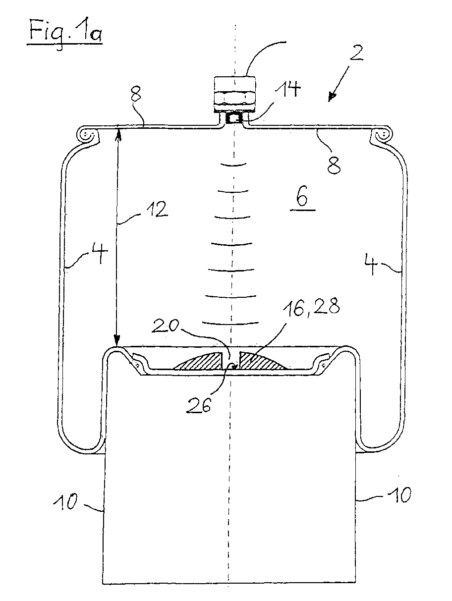
- the air spring 2 shown in Fig. 1a / 1b consists essentially of an air spring bellows 4, which encloses the pressurized air spring interior 6.
- the bellows 4 is closed on the chassis side by a cover plate 8.
- the rolling bellows 4 can roll on a rolling piston 10 fastened on the wheel side in the rhythm of the deflection process.
- an ultrasonic transducer 14 serving as a transmitter / receiver is attached to the cover plate 8. This transmitter / receiver 14 is opposed by a reflector 16 attached to the rolling piston 10.
- the ultrasound transducer 14 transmits at time intervals individual ultrasound pulses from which the clear height 12 of the air spring interior and - after they have passed from the reflector 16 have been reflected - on the now as Return ultrasonic transducer 14 serving receiver.
- the term of the respective Ultrasonic pulse the current clear spring height 12 certainly.
- the time between sending the Impulse and the reception of the echo a measure of that Spring height.
- the duration of an impulse depends on the Speed c with which the sound is in the Air spring spreads, and this in turn depends on the Temperature and density of air.
- a reference reflector 18 is introduced at a defined distance from the sound transmitter / receiver 14 in accordance with the prior art (FIG. 1b).
- the reference reflector 18 has become more axial Radiation direction immediately in front of the transducer 14 arranged. 1b and 3 show such Unit in which a reference reflector 18 in is positioned close to the transducer 14.
- the Depth 22 serves as a reference route. This eliminates the filigree and complex reference reflector 18 (Fig. 1b and 3), so that the housing of the height sensor 24 accordingly can be made shorter.
- Equation (I) applies to the transit time of the sound pulse to the target reflector 16 and back.
- FIG. 4 shows a concrete embodiment of a stop buffer 28 with an integrated reflector unit 32.
- This reflector unit 32 consists of a metal or plastic cylinder which is fastened on the rolling piston 10 with the aid of a screw 34.
- the reflector unit 32 In the direction of the ultrasonic transducer 14, the reflector unit 32 has a blind bore 20, the upper edge serving as the target reflector 16 and the bottom 26 of the depression 20 as the reference reflector.
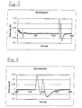
- the fifth shows the oscillogram of the echo signal.
- the double echo generated by the modified buffer 28 can be clearly seen.
- the first part echo arrives after time t target and the second after t ref .
- the time interval between the two echoes corresponds to the depth 22 of the blind bore 20.
Landscapes
- Engineering & Computer Science (AREA)
- Mechanical Engineering (AREA)
- General Engineering & Computer Science (AREA)
- Length Measuring Devices Characterised By Use Of Acoustic Means (AREA)
- Measurement Of Velocity Or Position Using Acoustic Or Ultrasonic Waves (AREA)
- Vehicle Body Suspensions (AREA)
- Fluid-Damping Devices (AREA)
- Geophysics And Detection Of Objects (AREA)
- Force Measurement Appropriate To Specific Purposes (AREA)
Abstract
Statt dessen ist der Reflektor zweistufig ausgebildet, wobei die eine Stufe als Zielreflektor (16) und die andere Stufe (26) als Referenzreflektor dient.
Vorzugsweise ist ein Anschlagpuffer (28) als zweistufiger Zielreflektor (16) ausgebildet, wobei die im Anschlagpuffer (28) ausgebildete Stufe als Sackbohrung (20) realisiert ist.
Description
Zur Bestimmung der Luftfederhöhe wird der variable lichte Abstand zwischen Abdeckplatte und Abrollkolben innerhalb der Luftfeder mit Hilfe von Ultraschall-Impulsen gemessen. Die meistverbreitete Methode ist die Impuls/Echo-Methode, wobei ein ultraschallsignal von einem am Deckel befestigten Ultraschallwandler ausgestrahlt wird, dann von einem am Abrollkolben angebrachten Reflektor reflektiert und schließlich von einem am Deckel angeordneten Ultraschallwandler aufgenommen und zur Auswertung an eine Auswerteelektronik weitergeleitet wird.
Aus der Laufzeit des Ultraschallsignals berechnet sich bei Kenntnis der Schallgeschwindigkeit die vom Ultraschallsignal zurückgelegte Strecke und damit die Federhöhe.
Hiermit ergeben sich verschiedene Nachteile: Das aus Stängel und Metallscheibe bestehende Fest-Target ist ein mechanisch empfindliches Bauteil. Da es eine gewisse Bauhöhe aufweist, verringert sich dadurch die lichte Höhe der Luftfeder und damit verringert sich auch der maximal mögliche Einfederungsweg. Andererseits vergrößert sich der für die Luftfeder erforderliche Bedarf an Bauhöhe. Ein weiterer Nachteil ist darin zu sehen, dass der Reflektor relativ nah am Ultraschallsender angeordnet ist und dass damit das über den weiteren Weg empfangene Nutzsignal von dem Referenzsignal möglicherweise bis zur Unkenntlichkeit überstrahlt wird.
Die vorliegende Erfindung will hier Abhilfe schaffen.
Von großer Bedeutung ist die Sicherheit bei der Auswertung. Ein Referenzreflektor in kurzem Abstand vor dem Schallwandler erzeugt in jedem Fall ein Echo. Dies ist unter Umständen so stark, dass es die Elektronik übersteuert, so dass im Einzelfall ein Echo aus größerer Entfernung nicht erkannt wird. Durch die Verwendung des erfindungsgemäß zweistufigen Reflektors haben Mess- und Referenzsignal vergleichbar große Amplituden, so dass diesbezUgliche Messschwierigkeiten entfallen. Wenn das Referenz- und das Zielecho etwa gleichstark sind, erhöht dies die Sicherheit bei der Auswertung der Laufzeiten. Es genügt eine einzige Aussteuerungsautomatik.
Ist die Sende/Empfangskomponente außermittig auf dem Deckel angeordnet (z. B. aus Rücksicht auf einen mittig angeordneten Träger), so kann selbstverständlich auch der zweistufige Zielreflektor außermittig oder schräg in Richtung auf die Sende/Empfangs-Komponente auf (bzw. in) dem Anschlagpuffer angeordnet sein.
Zwecks Messung der lichten Federhöhe 12 ist an der Abdeckplatte 8 ein als Sender/Empfänger dienender Ultraschallwandler 14 angebracht. Diesem Sender/Empfänger 14 steht ein am Abrollkolben 10 befestigter Reflektor 16 gegenüber.
In Richtung auf den Ultraschallwandler 14 weist die Reflektoreinheit 32 eine Sackbohrung 20 auf, wobei der obere Rand als Zielreflektor 16 und der Boden 26 der Vertiefung 20 als Referenzreflektor dient.
- 2
- Luftfeder
- 4
- Luftfeder-Rollbalg, Rollbalg
- 6
- Luftfeder-Innenraum
- 8
- Abdeckplatte (Anschlussteil)
- 10
- Abrollkolben (Anschlussteil)
- 12
- lichte Federhöhe
- 14
- Ultraschallwandler (Sender/Empfänger)
- 16
- Reflektor (Zielreflektor)
- 18
- Referenzreflektor
- 20
- Vertiefung, Sackbohrung, Stufe
- 22
- Tiefe, Referenzstrecke
- 24
- Gehäuse des Höhensensors
- 26
- Boden der Vertiefung 20, Referenzreflektor
- 28
- Anschlagpuffer, modifizierter Puffer
- 30
- Abstand Schallwandler/Zielreflektor
- 32
- Reflektoreinheit
- 34
- Schraube
Claims (5)
- Kraftfahrzeug-Luftfedersystem mit einer Ultraschall-Anordnung zur berührungslosen Abstandsmessung nach der Impuls/Echo-Methode,
wobei die Luftfeder (2) im wesentlichen aus einem Rollbalg (4) besteht, der an seinem einen Ende mit einer Abdeckplatte (8) als einem Anschlussteil und der an seinem anderen Ende mit einem Abrollkolben (10) als zweitem Anschlussteil abgeschlossen ist,
und wobei an einem (8 bzw. 10) der beiden Anschlussteile (8, 10) ein Ultraschall-Sender/-empfänger (14) und am anderen (10 bzw. 8) der beiden Anschlussteile ein Reflektor (16) angeordnet ist,
dadurch gekennzeichnet, dass der Reflektor zweistufig ausgebildet ist,
wobei die eine Stufe als Zielreflektor (1b) und die andere Stufe (2b) als Referenzreflektor dient. - Kraftfahrzeug-Luftfedersystem nach Anspruch 1,
dadurch gekennzeichnet, dass auf dem dem Luftfederinnenraum (6) zugewandten Ende des Abrollkolbens (10) oder auf der dem Luftfederinnenraum (6) zugewandten Seite der Abdeckplatte (8) ein Anscnlagpuffer (28) angeordnet ist,
wobei der Anschlagpuffer (28) als zweistufiger Zielreflektor (16) ausgebildet ist. - Kraftfahrzeug-Luftfedersystem nach Anspruch 1 oder 2,
dadurch gekennzeichnet, dass sich der zweistufige Reflektor (16) auf dem dem Luftfederinnenraum (6) zugewandten Ende des Abrollkolbens (10) und der Sender/-empfänger (14) auf der dem Luftfederinnenraum (6) zugewandten Seite der Abdeckplatte (8) angebracht ist. - Kraftfahrzeug-Luftfedersystem nach einem der Ansprüche 1 bis 3,
dadurch gekennzeichnet, dass die im Anschlagpuffer (28) ausgebildete Stufe durch eine zentrale Sackbohrung (20) realisiert ist. - Kraftfahrzeug -Luftfedersystem nach einem der Ansprüche 1 bis 4,
dadurch gekennzeichnet, dass der Durchmesser der Sackbohrung (20) 12 mm und die Tiefe (22) 7,5 mm beträgt.
Applications Claiming Priority (2)
| Application Number | Priority Date | Filing Date | Title |
|---|---|---|---|
| DE10051825 | 2000-10-19 | ||
| DE10051825A DE10051825A1 (de) | 2000-10-19 | 2000-10-19 | Kraftfahrzeug-Luftfedersystem mit Ultraschall-Messanordnung |
Publications (3)
| Publication Number | Publication Date |
|---|---|
| EP1199196A2 true EP1199196A2 (de) | 2002-04-24 |
| EP1199196A3 EP1199196A3 (de) | 2003-12-03 |
| EP1199196B1 EP1199196B1 (de) | 2006-10-11 |
Family
ID=7660324
Family Applications (1)
| Application Number | Title | Priority Date | Filing Date |
|---|---|---|---|
| EP01124634A Expired - Lifetime EP1199196B1 (de) | 2000-10-19 | 2001-10-16 | Kraftfahrzeug-Luftfedersystem mit Ultraschall-Messanordnung |
Country Status (6)
| Country | Link |
|---|---|
| US (1) | US6637269B2 (de) |
| EP (1) | EP1199196B1 (de) |
| AT (1) | ATE342175T1 (de) |
| DE (2) | DE10051825A1 (de) |
| HU (1) | HU228017B1 (de) |
| MX (1) | MXPA01010592A (de) |
Cited By (8)
| Publication number | Priority date | Publication date | Assignee | Title |
|---|---|---|---|---|
| WO2005003571A1 (de) * | 2003-07-04 | 2005-01-13 | Horst Siedle Gmbh & Co. Kg | Verfahren zur ermittlung einer aktuellen position eines in einem zylinder verschiebbar untergebrachten kolbens |
| US7221265B2 (en) | 2002-09-25 | 2007-05-22 | Kongsberg Automotive Asa | System for sensing level change in vehicles |
| WO2007137647A1 (de) * | 2006-05-31 | 2007-12-06 | Contitech Luftfedersysteme Gmbh | Bestimmung der federhöhe einer luftfeder nach einem impuls-laufzeitmessverfahren |
| WO2008086207A1 (en) * | 2007-01-08 | 2008-07-17 | Bfs Diversified Products, Llc | Reflector and gas spring assembly |
| WO2009015741A1 (de) * | 2007-07-27 | 2009-02-05 | Truma Gerätetechnik GmbH & Co. KG | Vorrichtung zum bestimmen der position eines kolbens in einem zylinder |
| CN104875571A (zh) * | 2015-06-15 | 2015-09-02 | 华中科技大学 | 一种车辆用减振缓冲机构 |
| EP3260318A1 (de) * | 2016-06-24 | 2017-12-27 | Continental Automotive GmbH | Fahrniveausteuerung für ein kraftfahrzeug |
| CN115263967A (zh) * | 2022-06-30 | 2022-11-01 | 东风商用车有限公司 | 一种带减震功能的商用车集成式空气弹簧及商用车 |
Families Citing this family (18)
| Publication number | Priority date | Publication date | Assignee | Title |
|---|---|---|---|---|
| DE10319669A1 (de) * | 2003-05-02 | 2004-11-18 | Continental Aktiengesellschaft | Niveauregelbare Luftfeder |
| JP2005112155A (ja) * | 2003-10-08 | 2005-04-28 | Hitachi Ltd | サスペンション装置 |
| US7490817B2 (en) * | 2005-01-04 | 2009-02-17 | Bfs Diversified Products Llc | Distance indicating system and method |
| US7364144B2 (en) | 2005-04-27 | 2008-04-29 | Bfs Diversified Products, Llc | Sensing and communication system and method |
| JP5100642B2 (ja) * | 2005-05-28 | 2012-12-19 | ビーエフエス デバーシファイド プロダクツ エルエルシー | 作動モジュール、空気ばねアセンブリ、車両サスペンションシステム、及び車両サスペンションシステムの作動方法 |
| US7420462B2 (en) | 2006-01-23 | 2008-09-02 | Bfs Diversified Products, Llc | Air spring distance indicating system and method |
| DE102006017275B4 (de) * | 2006-04-12 | 2011-01-05 | Gudzulic, Miro, Dipl.-Ing. (FH) | Luftfeder, Positioniermodul und Positioniereinrichtung |
| US7733239B2 (en) * | 2006-05-08 | 2010-06-08 | Bfs Diversified Products, Llc | Distance determining system and method |
| DE102006038469A1 (de) * | 2006-08-17 | 2008-02-28 | Astyx Gmbh | Abstandsmessvorrichtung und Verfahren zur Bestimmung eines Abstands und ein geeigneter Reflexionskörper |
| US9168804B2 (en) * | 2007-01-08 | 2015-10-27 | Firestone Industrial Products Company, Llc | End members, gas spring assemblies and suspension systems |
| GB0707129D0 (en) * | 2007-04-13 | 2007-05-23 | Bioinnovel Ltd | Fermenter monitor |
| CA2764155C (en) | 2009-06-01 | 2014-02-25 | Firestone Industrial Products Company, Llc | Height control module, gas spring assembly and method |
| US10464385B2 (en) | 2012-08-31 | 2019-11-05 | Firestone Industrial Products Company, Llc | Jounce bumpers and spring assemblies including same |
| DE102013217343B4 (de) | 2012-08-31 | 2022-10-20 | Firestone Industrial Products Company, Llc | Anschlagpuffer und diese umfassende federanordnungen |
| US8868294B2 (en) | 2012-09-28 | 2014-10-21 | Firestone Industrial Products Company, Llc | Adjustable hysteresis circuit for control of air suspension |
| CN104696412B (zh) * | 2015-03-24 | 2017-05-31 | 株洲时代新材料科技股份有限公司 | 舰用气囊隔振器 |
| DE102015212599B3 (de) * | 2015-07-06 | 2016-06-23 | Robert Bosch Gmbh | Ultraschallsensorvorrichtung zur Anordnung an einem Verkleidungsbauteil eines Fahrzeugs |
| CN107830105A (zh) * | 2017-10-27 | 2018-03-23 | 株洲时代新材料科技股份有限公司 | 一种预压式空气弹簧组件 |
Citations (1)
| Publication number | Priority date | Publication date | Assignee | Title |
|---|---|---|---|---|
| DE3620957A1 (de) | 1985-07-02 | 1987-01-08 | Dunlop Ltd | Federungssystem |
Family Cites Families (14)
| Publication number | Priority date | Publication date | Assignee | Title |
|---|---|---|---|---|
| US4543649A (en) * | 1983-10-17 | 1985-09-24 | Teknar, Inc. | System for ultrasonically detecting the relative position of a moveable device |
| US4798369A (en) * | 1987-11-03 | 1989-01-17 | The Firestone Tire & Rubber Company | Ultrasonic air spring system |
| US4938066A (en) * | 1988-01-29 | 1990-07-03 | Xecutek Corporation | Ultrasonic apparatus for measuring the speed of sound in a gaseous medium |
| US4918672A (en) * | 1988-08-11 | 1990-04-17 | Niles Parts Co., Ltd. | Ultrasonic distance sensor |
| US5104144A (en) * | 1990-09-25 | 1992-04-14 | Monroe Auto Equipment Company | Shock absorber with sonar position sensor |
| US5418758A (en) * | 1991-03-22 | 1995-05-23 | Connell Wagner (Old) Pty. Ltd. | Distance measurement system |
| US5642869A (en) * | 1995-12-01 | 1997-07-01 | Teleengineering, Inc. | Apparatus for detecting the distance between two objects |
| DE19648112C1 (de) * | 1996-11-21 | 1998-03-05 | Contitech Luftfedersyst Gmbh | Einrichtung zur berührungslosen Abstandsmessung |
| DE19700966C1 (de) * | 1997-01-14 | 1998-04-23 | Contitech Luftfedersyst Gmbh | Einrichtung zur berührungslosen Abstands- und Druckmessung innerhalb einer Luftfeder |
| DE19801054C1 (de) * | 1998-01-14 | 1999-07-29 | Mannesmann Sachs Ag | Kolben-Zylinderaggregat mit einer Bewegungserfassungseinrichtung |
| DE19811982C5 (de) * | 1998-03-19 | 2011-02-03 | Microsonic Gesellschaft für Mikroelektronik und Ultraschalltechnik mbH | Ultraschall-Luftfederanordnung |
| DE19820877C2 (de) * | 1998-05-09 | 2002-09-19 | Contitech Luftfedersyst Gmbh | Berührungslose Abstands- und Druckmessung innerhalb einer Luftfeder |
| DE19839483A1 (de) * | 1998-08-29 | 2000-03-02 | Contitech Luftfedersyst Gmbh | Luftfeder mit Ultraschall-Höhenmeßeinrichtung |
| US6109598A (en) * | 1999-06-29 | 2000-08-29 | Bridgestone/Firestone, Inc. | Air spring bumper utilizing a combination of materials |
-
2000
- 2000-10-19 DE DE10051825A patent/DE10051825A1/de not_active Withdrawn
-
2001
- 2001-10-16 DE DE50111185T patent/DE50111185D1/de not_active Expired - Lifetime
- 2001-10-16 EP EP01124634A patent/EP1199196B1/de not_active Expired - Lifetime
- 2001-10-16 AT AT01124634T patent/ATE342175T1/de not_active IP Right Cessation
- 2001-10-18 HU HU0104381A patent/HU228017B1/hu not_active IP Right Cessation
- 2001-10-19 MX MXPA01010592A patent/MXPA01010592A/es active IP Right Grant
- 2001-10-19 US US09/982,080 patent/US6637269B2/en not_active Expired - Fee Related
Patent Citations (1)
| Publication number | Priority date | Publication date | Assignee | Title |
|---|---|---|---|---|
| DE3620957A1 (de) | 1985-07-02 | 1987-01-08 | Dunlop Ltd | Federungssystem |
Cited By (11)
| Publication number | Priority date | Publication date | Assignee | Title |
|---|---|---|---|---|
| US7221265B2 (en) | 2002-09-25 | 2007-05-22 | Kongsberg Automotive Asa | System for sensing level change in vehicles |
| WO2005003571A1 (de) * | 2003-07-04 | 2005-01-13 | Horst Siedle Gmbh & Co. Kg | Verfahren zur ermittlung einer aktuellen position eines in einem zylinder verschiebbar untergebrachten kolbens |
| WO2007137647A1 (de) * | 2006-05-31 | 2007-12-06 | Contitech Luftfedersysteme Gmbh | Bestimmung der federhöhe einer luftfeder nach einem impuls-laufzeitmessverfahren |
| WO2008086207A1 (en) * | 2007-01-08 | 2008-07-17 | Bfs Diversified Products, Llc | Reflector and gas spring assembly |
| AU2008205075B2 (en) * | 2007-01-08 | 2011-09-29 | Bfs Diversified Products, Llc | Reflector and gas spring assembly |
| US8602399B2 (en) | 2007-01-08 | 2013-12-10 | Firestone Industrial Products Company, Llc | Reflector and gas spring assembly |
| WO2009015741A1 (de) * | 2007-07-27 | 2009-02-05 | Truma Gerätetechnik GmbH & Co. KG | Vorrichtung zum bestimmen der position eines kolbens in einem zylinder |
| CN104875571A (zh) * | 2015-06-15 | 2015-09-02 | 华中科技大学 | 一种车辆用减振缓冲机构 |
| CN104875571B (zh) * | 2015-06-15 | 2017-01-11 | 华中科技大学 | 一种车辆用减振缓冲机构 |
| EP3260318A1 (de) * | 2016-06-24 | 2017-12-27 | Continental Automotive GmbH | Fahrniveausteuerung für ein kraftfahrzeug |
| CN115263967A (zh) * | 2022-06-30 | 2022-11-01 | 东风商用车有限公司 | 一种带减震功能的商用车集成式空气弹簧及商用车 |
Also Published As
| Publication number | Publication date |
|---|---|
| EP1199196B1 (de) | 2006-10-11 |
| HUP0104381A3 (en) | 2005-03-29 |
| US6637269B2 (en) | 2003-10-28 |
| MXPA01010592A (es) | 2003-08-20 |
| ATE342175T1 (de) | 2006-11-15 |
| HU228017B1 (hu) | 2012-08-28 |
| US20020046608A1 (en) | 2002-04-25 |
| EP1199196A3 (de) | 2003-12-03 |
| DE50111185D1 (de) | 2006-11-23 |
| DE10051825A1 (de) | 2002-04-25 |
| HUP0104381A2 (en) | 2002-06-29 |
| HU0104381D0 (en) | 2001-12-28 |
Similar Documents
| Publication | Publication Date | Title |
|---|---|---|
| EP1199196A2 (de) | Kraftfahrzeug-Luftfedersystem mit Ultraschall-Messanordnung | |
| EP0957373A2 (de) | Berührungslose Abstands- und Druckmessung innerhalb einer Luftfeder | |
| DE3519254C2 (de) | ||
| DE4338743C2 (de) | Verfahren und Vorrichtung zum Betrieb eines Ultraschallsensors | |
| DE3016323C3 (de) | Gerät zur akustischen Messung der Dichte einer Flüssigkeit | |
| DE10341128A1 (de) | Vorrichtung und Verfahren zur Erfassung eines momentanen Abstandes eines Kraftfahrzeugs von einem Hindernis | |
| CH664834A5 (de) | Schall- bzw. ultraschall-entfernungsmessgeraet. | |
| DE8702817U1 (de) | Vorrichtung zum Anzeigen der Bewegungen eines beweglichen Teils eines Teleskopstoßdämpfers für Motorfahrzeuge im Verhältnis zum feststehenden Teil | |
| DE4335728C2 (de) | Verfahren und Vorrichtung zur Ultraschall-Abstandsmessung | |
| EP1296159B1 (de) | Verfahren zur Abstandsmessung | |
| EP3091371A1 (de) | Verfahren zur bestimmung einer dämpfung eines ultraschallsignals, fahrerassistenzsystem sowie kraftfahrzeug | |
| WO1986005149A1 (fr) | Dispositif de protection des passagers d'un vehicule a moteur lors d'accidents dus a des telescopages | |
| EP0984300A2 (de) | Einparkhilfe für ein Kraftfahrzeug | |
| EP0965057B1 (de) | Ultraschall-abstandsmesssystem mit im zeitmultiplex übertragenen digitalen messsignalen | |
| DE19701530C1 (de) | Einrichtung zur Bestimmung des axialen Abstandes zweier Endglieder einer Gasdruckfeder | |
| EP1460396B1 (de) | Verfahren und Vorrichtung zur Ultraschall-Füllstandsmessung einer Flüssigkeit in einem Behälter | |
| DE3044354C2 (de) | Verfahren zur Feststellung des Erreichens eines vorbestimmten Füllstandes in einem Behälter und Vorrichtung zur Durchführung des Verfahrens | |
| WO2007137647A1 (de) | Bestimmung der federhöhe einer luftfeder nach einem impuls-laufzeitmessverfahren | |
| DE102012025065A1 (de) | Verfahren zur Detektion eines Störsignalanteils in einem elektrischen Empfangssignal eines Ultraschallsensors, Ultraschallsensorvorrichtung und Kraftfahrzeug | |
| EP1295737B1 (de) | Bestimmung von Federhöhe und Druck in Federelementen, insbesondere Luftfedern, für Kraftfahrzeuge | |
| EP1582889B1 (de) | Verfahren zur temperaturunabhängigen Abstandsmessung | |
| DE102016212792B3 (de) | Verfahren zur Einstellung mindestens eines Parameters eines Ultraschallsensors und/oder einer Auswerte- und Steuereinheit und Vorrichtung zur Abstands-Bestimmung von Objekten | |
| DE3330063A1 (de) | Fluessigkeitsstandmesser fuer fluessigkeitsbehaelter | |
| DE3883672T2 (de) | Doppler-Sicherheits-Geschwindigkeitsmesseinrichtung. | |
| EP1859236B1 (de) | Vorrichtung zum messen des füllstandes einer flüssigkeit in einem behälter mit einem ultraschallwandler |
Legal Events
| Date | Code | Title | Description |
|---|---|---|---|
| PUAI | Public reference made under article 153(3) epc to a published international application that has entered the european phase |
Free format text: ORIGINAL CODE: 0009012 |
|
| AK | Designated contracting states |
Kind code of ref document: A2 Designated state(s): AT BE CH CY DE DK ES FI FR GB GR IE IT LI LU MC NL PT SE TR |
|
| AX | Request for extension of the european patent |
Free format text: AL;LT;LV;MK;RO;SI |
|
| PUAL | Search report despatched |
Free format text: ORIGINAL CODE: 0009013 |
|
| AK | Designated contracting states |
Kind code of ref document: A3 Designated state(s): AT BE CH CY DE DK ES FI FR GB GR IE IT LI LU MC NL PT SE TR |
|
| AX | Request for extension of the european patent |
Extension state: AL LT LV MK RO SI |
|
| REG | Reference to a national code |
Ref country code: SE Ref legal event code: TRGR |
|
| 17P | Request for examination filed |
Effective date: 20040603 |
|
| AKX | Designation fees paid |
Designated state(s): AT BE CH CY DE DK ES FI FR GB GR IE IT LI LU MC NL PT SE TR |
|
| 17Q | First examination report despatched |
Effective date: 20040729 |
|
| GRAP | Despatch of communication of intention to grant a patent |
Free format text: ORIGINAL CODE: EPIDOSNIGR1 |
|
| GRAS | Grant fee paid |
Free format text: ORIGINAL CODE: EPIDOSNIGR3 |
|
| GRAA | (expected) grant |
Free format text: ORIGINAL CODE: 0009210 |
|
| AK | Designated contracting states |
Kind code of ref document: B1 Designated state(s): AT BE CH CY DE DK ES FI FR GB GR IE IT LI LU MC NL PT SE TR |
|
| PG25 | Lapsed in a contracting state [announced via postgrant information from national office to epo] |
Ref country code: IE Free format text: LAPSE BECAUSE OF FAILURE TO SUBMIT A TRANSLATION OF THE DESCRIPTION OR TO PAY THE FEE WITHIN THE PRESCRIBED TIME-LIMIT Effective date: 20061011 Ref country code: FI Free format text: LAPSE BECAUSE OF FAILURE TO SUBMIT A TRANSLATION OF THE DESCRIPTION OR TO PAY THE FEE WITHIN THE PRESCRIBED TIME-LIMIT Effective date: 20061011 |
|
| REG | Reference to a national code |
Ref country code: GB Ref legal event code: FG4D Free format text: NOT ENGLISH |
|
| PG25 | Lapsed in a contracting state [announced via postgrant information from national office to epo] |
Ref country code: LI Free format text: LAPSE BECAUSE OF NON-PAYMENT OF DUE FEES Effective date: 20061031 Ref country code: MC Free format text: LAPSE BECAUSE OF NON-PAYMENT OF DUE FEES Effective date: 20061031 Ref country code: CH Free format text: LAPSE BECAUSE OF NON-PAYMENT OF DUE FEES Effective date: 20061031 |
|
| REG | Reference to a national code |
Ref country code: CH Ref legal event code: EP |
|
| REG | Reference to a national code |
Ref country code: IE Ref legal event code: FG4D Free format text: LANGUAGE OF EP DOCUMENT: GERMAN |
|
| REF | Corresponds to: |
Ref document number: 50111185 Country of ref document: DE Date of ref document: 20061123 Kind code of ref document: P |
|
| PG25 | Lapsed in a contracting state [announced via postgrant information from national office to epo] |
Ref country code: DK Free format text: LAPSE BECAUSE OF FAILURE TO SUBMIT A TRANSLATION OF THE DESCRIPTION OR TO PAY THE FEE WITHIN THE PRESCRIBED TIME-LIMIT Effective date: 20070111 |
|
| PG25 | Lapsed in a contracting state [announced via postgrant information from national office to epo] |
Ref country code: ES Free format text: LAPSE BECAUSE OF FAILURE TO SUBMIT A TRANSLATION OF THE DESCRIPTION OR TO PAY THE FEE WITHIN THE PRESCRIBED TIME-LIMIT Effective date: 20070122 |
|
| PG25 | Lapsed in a contracting state [announced via postgrant information from national office to epo] |
Ref country code: PT Free format text: LAPSE BECAUSE OF FAILURE TO SUBMIT A TRANSLATION OF THE DESCRIPTION OR TO PAY THE FEE WITHIN THE PRESCRIBED TIME-LIMIT Effective date: 20070319 |
|
| GBV | Gb: ep patent (uk) treated as always having been void in accordance with gb section 77(7)/1977 [no translation filed] |
Effective date: 20061011 |
|
| ET | Fr: translation filed | ||
| REG | Reference to a national code |
Ref country code: CH Ref legal event code: PL |
|
| REG | Reference to a national code |
Ref country code: IE Ref legal event code: FD4D |
|
| PLBE | No opposition filed within time limit |
Free format text: ORIGINAL CODE: 0009261 |
|
| 26N | No opposition filed |
Effective date: 20070712 |
|
| PG25 | Lapsed in a contracting state [announced via postgrant information from national office to epo] |
Ref country code: GB Free format text: LAPSE BECAUSE OF FAILURE TO SUBMIT A TRANSLATION OF THE DESCRIPTION OR TO PAY THE FEE WITHIN THE PRESCRIBED TIME-LIMIT Effective date: 20061011 |
|
| BERE | Be: lapsed |
Owner name: CONTITECH LUFTFEDERSYSTEME G.M.B.H. Effective date: 20061031 |
|
| PG25 | Lapsed in a contracting state [announced via postgrant information from national office to epo] |
Ref country code: AT Free format text: LAPSE BECAUSE OF NON-PAYMENT OF DUE FEES Effective date: 20061016 |
|
| PG25 | Lapsed in a contracting state [announced via postgrant information from national office to epo] |
Ref country code: GR Free format text: LAPSE BECAUSE OF FAILURE TO SUBMIT A TRANSLATION OF THE DESCRIPTION OR TO PAY THE FEE WITHIN THE PRESCRIBED TIME-LIMIT Effective date: 20070112 |
|
| PG25 | Lapsed in a contracting state [announced via postgrant information from national office to epo] |
Ref country code: LU Free format text: LAPSE BECAUSE OF NON-PAYMENT OF DUE FEES Effective date: 20061016 |
|
| PG25 | Lapsed in a contracting state [announced via postgrant information from national office to epo] |
Ref country code: CY Free format text: LAPSE BECAUSE OF FAILURE TO SUBMIT A TRANSLATION OF THE DESCRIPTION OR TO PAY THE FEE WITHIN THE PRESCRIBED TIME-LIMIT Effective date: 20061011 |
|
| PG25 | Lapsed in a contracting state [announced via postgrant information from national office to epo] |
Ref country code: BE Free format text: LAPSE BECAUSE OF FAILURE TO SUBMIT A TRANSLATION OF THE DESCRIPTION OR TO PAY THE FEE WITHIN THE PRESCRIBED TIME-LIMIT Effective date: 20061031 |
|
| PGFP | Annual fee paid to national office [announced via postgrant information from national office to epo] |
Ref country code: FR Payment date: 20141022 Year of fee payment: 14 Ref country code: SE Payment date: 20141021 Year of fee payment: 14 |
|
| PGFP | Annual fee paid to national office [announced via postgrant information from national office to epo] |
Ref country code: NL Payment date: 20141021 Year of fee payment: 14 |
|
| PGFP | Annual fee paid to national office [announced via postgrant information from national office to epo] |
Ref country code: IT Payment date: 20141030 Year of fee payment: 14 |
|
| PGFP | Annual fee paid to national office [announced via postgrant information from national office to epo] |
Ref country code: TR Payment date: 20131016 Year of fee payment: 13 |
|
| REG | Reference to a national code |
Ref country code: SE Ref legal event code: EUG |
|
| REG | Reference to a national code |
Ref country code: NL Ref legal event code: MM Effective date: 20151101 |
|
| PG25 | Lapsed in a contracting state [announced via postgrant information from national office to epo] |
Ref country code: IT Free format text: LAPSE BECAUSE OF NON-PAYMENT OF DUE FEES Effective date: 20151016 |
|
| REG | Reference to a national code |
Ref country code: FR Ref legal event code: ST Effective date: 20160630 |
|
| PG25 | Lapsed in a contracting state [announced via postgrant information from national office to epo] |
Ref country code: FR Free format text: LAPSE BECAUSE OF NON-PAYMENT OF DUE FEES Effective date: 20151102 Ref country code: SE Free format text: LAPSE BECAUSE OF NON-PAYMENT OF DUE FEES Effective date: 20151017 Ref country code: NL Free format text: LAPSE BECAUSE OF NON-PAYMENT OF DUE FEES Effective date: 20151101 |
|
| PG25 | Lapsed in a contracting state [announced via postgrant information from national office to epo] |
Ref country code: TR Free format text: LAPSE BECAUSE OF NON-PAYMENT OF DUE FEES Effective date: 20151016 |
|
| PGFP | Annual fee paid to national office [announced via postgrant information from national office to epo] |
Ref country code: DE Payment date: 20181031 Year of fee payment: 18 |
|
| REG | Reference to a national code |
Ref country code: DE Ref legal event code: R119 Ref document number: 50111185 Country of ref document: DE |
|
| PG25 | Lapsed in a contracting state [announced via postgrant information from national office to epo] |
Ref country code: DE Free format text: LAPSE BECAUSE OF NON-PAYMENT OF DUE FEES Effective date: 20200501 |