EP1199148A1 - Fabrication d'une bandelette par extrusion d'un tube puis aplatissement du tube - Google Patents
Fabrication d'une bandelette par extrusion d'un tube puis aplatissement du tube Download PDFInfo
- Publication number
- EP1199148A1 EP1199148A1 EP01123735A EP01123735A EP1199148A1 EP 1199148 A1 EP1199148 A1 EP 1199148A1 EP 01123735 A EP01123735 A EP 01123735A EP 01123735 A EP01123735 A EP 01123735A EP 1199148 A1 EP1199148 A1 EP 1199148A1
- Authority
- EP
- European Patent Office
- Prior art keywords
- rubber
- tube
- extrusion
- die
- raw rubber
- Prior art date
- Legal status (The legal status is an assumption and is not a legal conclusion. Google has not performed a legal analysis and makes no representation as to the accuracy of the status listed.)
- Granted
Links
- 238000004519 manufacturing process Methods 0.000 title claims abstract description 31
- 229920001971 elastomer Polymers 0.000 claims abstract description 78
- 239000005060 rubber Substances 0.000 claims abstract description 78
- 238000001125 extrusion Methods 0.000 claims description 47
- 240000007817 Olea europaea Species 0.000 claims description 32
- 238000000034 method Methods 0.000 claims description 17
- 238000000151 deposition Methods 0.000 claims description 14
- 238000004804 winding Methods 0.000 claims description 14
- 239000000463 material Substances 0.000 claims description 10
- 230000008021 deposition Effects 0.000 claims description 5
- 238000011144 upstream manufacturing Methods 0.000 claims description 5
- 239000000470 constituent Substances 0.000 claims description 4
- 238000013022 venting Methods 0.000 claims description 3
- 239000007789 gas Substances 0.000 claims 1
- RRHGJUQNOFWUDK-UHFFFAOYSA-N Isoprene Chemical compound CC(=C)C=C RRHGJUQNOFWUDK-UHFFFAOYSA-N 0.000 abstract description 8
- 229920001195 polyisoprene Polymers 0.000 abstract description 8
- 239000000203 mixture Substances 0.000 description 7
- 239000000047 product Substances 0.000 description 7
- 238000011045 prefiltration Methods 0.000 description 4
- 238000005096 rolling process Methods 0.000 description 4
- 238000004073 vulcanization Methods 0.000 description 3
- 239000000654 additive Substances 0.000 description 2
- 230000000996 additive effect Effects 0.000 description 2
- YFXPPSKYMBTNAV-UHFFFAOYSA-N bensultap Chemical compound C=1C=CC=CC=1S(=O)(=O)SCC(N(C)C)CSS(=O)(=O)C1=CC=CC=C1 YFXPPSKYMBTNAV-UHFFFAOYSA-N 0.000 description 2
- 239000007787 solid Substances 0.000 description 2
- NINIDFKCEFEMDL-UHFFFAOYSA-N Sulfur Chemical compound [S] NINIDFKCEFEMDL-UHFFFAOYSA-N 0.000 description 1
- 238000009825 accumulation Methods 0.000 description 1
- 239000011324 bead Substances 0.000 description 1
- 230000001419 dependent effect Effects 0.000 description 1
- 238000006073 displacement reaction Methods 0.000 description 1
- 238000005553 drilling Methods 0.000 description 1
- 230000000694 effects Effects 0.000 description 1
- 238000010070 extrusion (rubber) Methods 0.000 description 1
- 239000000835 fiber Substances 0.000 description 1
- 239000012535 impurity Substances 0.000 description 1
- 238000002955 isolation Methods 0.000 description 1
- 238000003754 machining Methods 0.000 description 1
- 238000000465 moulding Methods 0.000 description 1
- 231100000957 no side effect Toxicity 0.000 description 1
- 239000012783 reinforcing fiber Substances 0.000 description 1
- 239000011265 semifinished product Substances 0.000 description 1
- 229910052717 sulfur Inorganic materials 0.000 description 1
- 239000011593 sulfur Substances 0.000 description 1
Images



Classifications
-
- B—PERFORMING OPERATIONS; TRANSPORTING
- B29—WORKING OF PLASTICS; WORKING OF SUBSTANCES IN A PLASTIC STATE IN GENERAL
- B29D—PRODUCING PARTICULAR ARTICLES FROM PLASTICS OR FROM SUBSTANCES IN A PLASTIC STATE
- B29D30/00—Producing pneumatic or solid tyres or parts thereof
- B29D30/06—Pneumatic tyres or parts thereof (e.g. produced by casting, moulding, compression moulding, injection moulding, centrifugal casting)
- B29D30/08—Building tyres
-
- B—PERFORMING OPERATIONS; TRANSPORTING
- B29—WORKING OF PLASTICS; WORKING OF SUBSTANCES IN A PLASTIC STATE IN GENERAL
- B29D—PRODUCING PARTICULAR ARTICLES FROM PLASTICS OR FROM SUBSTANCES IN A PLASTIC STATE
- B29D30/00—Producing pneumatic or solid tyres or parts thereof
- B29D30/06—Pneumatic tyres or parts thereof (e.g. produced by casting, moulding, compression moulding, injection moulding, centrifugal casting)
- B29D30/52—Unvulcanised treads, e.g. on used tyres; Retreading
- B29D30/58—Applying bands of rubber treads, i.e. applying camel backs
- B29D30/60—Applying bands of rubber treads, i.e. applying camel backs by winding narrow strips
-
- B—PERFORMING OPERATIONS; TRANSPORTING
- B29—WORKING OF PLASTICS; WORKING OF SUBSTANCES IN A PLASTIC STATE IN GENERAL
- B29C—SHAPING OR JOINING OF PLASTICS; SHAPING OF MATERIAL IN A PLASTIC STATE, NOT OTHERWISE PROVIDED FOR; AFTER-TREATMENT OF THE SHAPED PRODUCTS, e.g. REPAIRING
- B29C48/00—Extrusion moulding, i.e. expressing the moulding material through a die or nozzle which imparts the desired form; Apparatus therefor
- B29C48/03—Extrusion moulding, i.e. expressing the moulding material through a die or nozzle which imparts the desired form; Apparatus therefor characterised by the shape of the extruded material at extrusion
- B29C48/09—Articles with cross-sections having partially or fully enclosed cavities, e.g. pipes or channels
-
- B—PERFORMING OPERATIONS; TRANSPORTING
- B29—WORKING OF PLASTICS; WORKING OF SUBSTANCES IN A PLASTIC STATE IN GENERAL
- B29C—SHAPING OR JOINING OF PLASTICS; SHAPING OF MATERIAL IN A PLASTIC STATE, NOT OTHERWISE PROVIDED FOR; AFTER-TREATMENT OF THE SHAPED PRODUCTS, e.g. REPAIRING
- B29C48/00—Extrusion moulding, i.e. expressing the moulding material through a die or nozzle which imparts the desired form; Apparatus therefor
- B29C48/25—Component parts, details or accessories; Auxiliary operations
- B29C48/30—Extrusion nozzles or dies
- B29C48/32—Extrusion nozzles or dies with annular openings, e.g. for forming tubular articles
- B29C48/325—Extrusion nozzles or dies with annular openings, e.g. for forming tubular articles being adjustable, i.e. having adjustable exit sections
-
- B—PERFORMING OPERATIONS; TRANSPORTING
- B29—WORKING OF PLASTICS; WORKING OF SUBSTANCES IN A PLASTIC STATE IN GENERAL
- B29C—SHAPING OR JOINING OF PLASTICS; SHAPING OF MATERIAL IN A PLASTIC STATE, NOT OTHERWISE PROVIDED FOR; AFTER-TREATMENT OF THE SHAPED PRODUCTS, e.g. REPAIRING
- B29C48/00—Extrusion moulding, i.e. expressing the moulding material through a die or nozzle which imparts the desired form; Apparatus therefor
- B29C48/25—Component parts, details or accessories; Auxiliary operations
- B29C48/30—Extrusion nozzles or dies
- B29C48/35—Extrusion nozzles or dies with rollers
-
- B—PERFORMING OPERATIONS; TRANSPORTING
- B29—WORKING OF PLASTICS; WORKING OF SUBSTANCES IN A PLASTIC STATE IN GENERAL
- B29C—SHAPING OR JOINING OF PLASTICS; SHAPING OF MATERIAL IN A PLASTIC STATE, NOT OTHERWISE PROVIDED FOR; AFTER-TREATMENT OF THE SHAPED PRODUCTS, e.g. REPAIRING
- B29C48/00—Extrusion moulding, i.e. expressing the moulding material through a die or nozzle which imparts the desired form; Apparatus therefor
- B29C48/001—Combinations of extrusion moulding with other shaping operations
- B29C48/0019—Combinations of extrusion moulding with other shaping operations combined with shaping by flattening, folding or bending
-
- B—PERFORMING OPERATIONS; TRANSPORTING
- B29—WORKING OF PLASTICS; WORKING OF SUBSTANCES IN A PLASTIC STATE IN GENERAL
- B29C—SHAPING OR JOINING OF PLASTICS; SHAPING OF MATERIAL IN A PLASTIC STATE, NOT OTHERWISE PROVIDED FOR; AFTER-TREATMENT OF THE SHAPED PRODUCTS, e.g. REPAIRING
- B29C48/00—Extrusion moulding, i.e. expressing the moulding material through a die or nozzle which imparts the desired form; Apparatus therefor
- B29C48/03—Extrusion moulding, i.e. expressing the moulding material through a die or nozzle which imparts the desired form; Apparatus therefor characterised by the shape of the extruded material at extrusion
- B29C48/09—Articles with cross-sections having partially or fully enclosed cavities, e.g. pipes or channels
- B29C48/10—Articles with cross-sections having partially or fully enclosed cavities, e.g. pipes or channels flexible, e.g. blown foils
Definitions
- the present invention relates to the fitting of rubber products for the manufacture of tires. More specifically, the present invention relates to the manufacture of a tire by winding strips and it relates to the manufacture of products semi-finished in the form of strips.
- patent application EP 0 264 600 proposes to use a volumetric type extrusion to ensure the removal of the products in rubber with great precision.
- Patent application EP 0 690 229 proposes a positive displacement pump used to continuously extrude a raw rubber strip with great precision.
- a well known problem in the tire industry is that certain mixtures sulfur vulcanizable rubbers are quite difficult to extrude: the mixture tends to to crumble, does not have a smooth surface downstream of the extrusion but rather a surface grainy, bumpy, rough, sometimes showing signs of tearing. It is difficult to give such mixtures a precise and regular shape like a strip. it causes difficulties in handling extruded semi-finished products. This implies also difficulties in depositing such products on a raw tire blank in during manufacturing because the raw tights of such mixtures are generally bad.
- the invention proposes to form a strip by first manufacturing a tube which is subsequently overwrites.
- the extrusion of a rubber tube is done thanks to a cylindrical die containing an olive also cylindrical and of size slightly smaller so as to leave a gap of revolution between the nozzle and the olive.
- a cylindrical die containing an olive also cylindrical and of size slightly smaller so as to leave a gap of revolution between the nozzle and the olive.
- the cylindrical shape is not limiting, other shapes can be envisaged, including an oval section.
- the form of revolution is however advantageous for machining of parts.
- FIG 2 we see a core 30 of substantially toroidal shape, constituting a benchmark for the manufacture of a tire.
- This manufacturing technique is known.
- an extruder mounted on a handling robot is used allowing all the desired relative positions between said receiving surface and the die, this being positioned opposite the receiving surface for an extrusion of the shape tubular in the vicinity of the receiving surface, the tubular shape being flattened on the surface reception directly after extrusion.
- the raw rubber pump 10 constituting a possible example extruder.
- the raw rubber pump 10 is supported by a handling robot 19.
- the rubber pump essentially comprises a booster screw 102, one or more pistons 101 and an extrusion die 1. From a rubber band 2, the pump allows to deposit a strip 22 on the surface S of the core 30. A roller 40 facilitates the deposit.
- the handling robot 19 makes it possible to move the sector closer or further away extrusion 1 relative to the core 30 along the axis X, to move it transversely along the Y axis, and also allows the rubber pump to rotate around the ⁇ axis.
- the axis ⁇ passes substantially through the place where the strip 22 joins the surface S.
- the machine is placed under the control of an automaton which allows it to be controlled from appropriately.
- an automaton which allows it to be controlled from appropriately.
- speed “V” of screw 102 mechanically linked to the operating speed of piston (s) 101, effective setting radius "r" (different depending on the area of the tire - for example bead or tread -, or different from a winding to the other in case of superposition of windings to make the strip of bearing), speed of rotation "N" of the core 30.
- a volumetric extruder is used, the flow rate of extruded raw rubber being controlled in particular as a function of the speed of rotation of the receiving surface and the ribbon depositing radius.
- a die 1 in Figure 1, we see in more detail a first embodiment of a die 1 according to the invention.
- This comprises a prefilter 17 mounted on a rubber pump 10.
- the roller 40 cooperates with the core 30 downstream of the extrusion orifice, located in the plane IV-IV.
- Raw rubber 20 is discharged under pressure by the rubber pump 10 and reaches to the die 1.
- the die 1 comprises a nozzle 11 and an olive 12 fixed to the nozzle, and obscuring partially the extrusion orifice so as to provide a gap 15 between the nozzle and the olive, the air gap leading to an extrusion section of suitable shape.
- the rubber is extruded in the form of a tube 21.
- Part 210 of the tube 21 is close to the receiving surface S and another part is further away.
- the tube 21 is flattened by the action of the roller 40 cooperating with the core 30, to form a strip 22 by bonding of the walls of the tube 21.
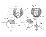
- the olive 12 is extended by a tail 18, mounted in an ad hoc hole on the prefilière 17, and maintained by a nut 180 opposing an expulsion of the olive 12 under the effect of the rubber discharge pressure.
- a tail 18 has a pipe 13 terminated by a connector 14 to which one can easily connect a tube appropriate. Line 13 crosses olive 12 and opens into the extrusion orifice. The venting can possibly be assisted by a depression. But the event is not essential because there is no accumulation of gas during the operation of the invention.
- the olive 12 advantageously comprises radial wings 121 (see FIG. 3) which center the olive 12 inside the nozzle 11.
- the position of the olive inside the nozzle could be adjustable between a centered position and eccentric positions, which can favor a non-axisymmetric extrusion of the tube 21.
- the tool proposed by the present invention can be very easily adapted to different sizes of strips that we have to make. It is not always possible to act on piloting the extrusion to go from a small strip to a larger strip. With the variants represented in FIGS. 5 to 9, it is very easy to replace the die extrusion because it is mounted via a ring 16 on the prefilter 17 and accessible from the side of the extrusion orifice. We can very easily, by unscrewing the ring 16, replace the assembly constituted by the nozzle 11 and the olive 12A or 12B.
- the olive has a ring forming a boss 120 upstream of the end which is to the right of the extrusion orifice.
- the 12B olive comprises, as already indicated, wings 121 which allow it to be centered. The distance between the boss 120 and the extrusion orifice is sufficient for a continuous ring to reform into downstream of any impurity blocked at 150B air gap, which if necessary is determined experimentally.
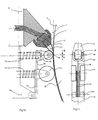
- Figures 10 and 11 illustrate in more detail a rolling that can be performed in downstream of the actual extrusion orifice.
- the core 30 and the surface of reception S We also see the die 1, comprising a nozzle 11 inside which has mounted an olive 12.
- a roller 40 is mounted on a yoke 45 itself supported by a arm 46 articulated to a support 44.
- the support 44 is integral with the rubber pump 10.
- a spring 42 acts between the support 44 and the roller 40.
- the roller 40 thus exerts pressure controlled towards the core 30.
- two auxiliary rollers 41 each mounted on a flange 48.
- Each of the flanges 48 is mounted on an arm 47, articulated on the support 44.
- Springs 43 act between each of the arms 47 and the support 44, for a function comparable to that of spring 42.
- rollers 40 and auxiliary rollers 41 applying forces substantially radial, of well controlled intensity, chosen experimentally, possibly adjustable. It is advantageous to have springs of great flexibility in order to exert a rolling effort substantially constant, even in the event of a runout or local imperfection in the removal of the rubber.
- the roller 40 performs a first crushing of the tube 21 which has just been extruded by die 1, which positions and sticks on the receiving surface S the middle part of the strip 22.
- the auxiliary rollers 41 press the edges of the strip 22 on the surface of reception S.
- Figures 12 and 13 help to understand an advantage of the invention. For different reasons among which we can cite the high precision of laying rubber, it it is desirable that the head of the rubber pump 10 be positioned as close as possible from where you want to deposit the rubber on the tire blank manufacturing course.
- the extruders used for the removal of test strips rubber are relatively bulky.
- the conventionally extruded section being rectangular, in conventional devices, the die that allows profiling the strip tire has a size which is necessarily greater than the cross section of the rubber strip that you want to deposit.
- the invention therefore provides a narrower extrusion die than the strip to extruded.
- a narrower extrusion die than the strip to extruded.
- the strip removal scheme respects as much the shape of the tire as possible.
- the problem that arises is that the head of the rubber pump 10, that is to say the die which profile rubber, due to its size, can strike raw rubber which has been deposited to form the adjacent circumferential rib.
- FIG. 12 is a view in the direction of the arrows AA in Figure 10, the roller 40 not being represented.
- the tube 21 is transformed into a strip 22 by flattening.
- the strip 22 is of a width "L" greater than the diameter "d" of the tube 21. Thanks to the invention, it can be seen that it is possible to deposit, on a blank of tire 50 during manufacture, strips 22 to form by superposition of rubber ribs 51 without being hampered by the stacks made at one position transverse offset.
- FIG. 13 is a view in the direction of the arrows BB in FIG. 10. It makes it possible to understand that even the rolling device with three rollers 40 and 41 proposed by the invention is of a size close to the width of the strip 22.
- the carriage caster (carrying the rollers 40 and 41) easily penetrates between the raw rubber cords.
- FIG. 14 illustrates an application of the invention to the addition of a material inside of the tube 21, so as to complete the vulcanizable rubber composition.
- a material inside of the tube 21, so as to complete the vulcanizable rubber composition can be by example of the vulcanization system, and / or any suitable additive.
- This addition is made when installing the strip 22, in a method of depositing a constituent comprising raw rubber at during the manufacture of a tire, the removal being carried out by winding a strip on a rotary support having a receiving surface S, the ribbon being manufactured as indicated above. We can however consider achieving a semi-finished in this way.
- the die 1B comprises a nozzle 11B and an olive 12B.
- 12B olive has a pipe 13B which crosses the olive 12B and opens into the orifice extrusion.
- Appropriate means make it possible to introduce a material 23 inside the tube 21.
- a certain amount of material 23 is thus continuously added to the raw rubber at the same time that a strip 22 is formed and that it is applied to the support of manufacturing 30.
- the machine control automaton according to the invention of course ensures the respect for controlled proportion between the material 23 and the extruded rubber 20. These proportions are not necessarily constant.
- the dosage of material 23 can be variable, the proportion being adjusted according to the location where the strip 22 in the tire.
- Figures 15 and 16 illustrate the result obtained when three towers are superimposed complete with a strip 22 wound on a revolution support such as a rotating core serving as a manufacturing reference for a tire.
- a non-homogeneity all the more important as the thickness “e” of the strip is important
- the azimuth of laying of the start 22A of the strip which is quite difficult to hide even when positioning correctly the azimuth of the end 22B of the strip.
- Figures 17 to 20 illustrate a another variant of the invention which makes it possible to achieve this. To this end, we vary the thickness of said wall of the rubber tube to obtain a variation in thickness of the strip.
- the olive 12B is extended by a tail 18B, mounted in an ad hoc drilling on the prefilter 17.
- the tail 18B penetrates into a cylinder 182B and is terminated by a disc 181B forming a piston sliding in said cylinder 182B.
- a movement control device 183B acts on the relative position of the tail 18B relative to prefilter 17, for example by injecting or withdrawing a quantity oil determined in chamber 184B. So the position of the 12B olive inside the nozzle 11 (figure 18) is adjustable in a direction parallel to the flow of raw rubber in the air gap. Furthermore, just upstream of the extrusion orifice, the nozzle 11 and the olive 12B have a frustoconical surface. In this way, by acting on the relative position of the olive 12B in the nozzle 11, the thickness of the air gap is varied and, by way of Consequently, the thickness of the extruded rubber tube.
- FIG. 18 shows the extrusion of a tube whose walls are of a thickness such that, once pressed against the support S, a strip of thickness "e2" is obtained for the position of the olive 12B illustrated in FIGS. 17 and 18.
- FIGS. 19 and 20 we see another position of the olive 12B, more inside the nozzle 11. In the configuration of these members as shown, the air gap is smaller.
- the width of the strip extruded which mainly depends on the diameter "d" of the tube, is substantially independent of thickness.
Landscapes
- Engineering & Computer Science (AREA)
- Mechanical Engineering (AREA)
- Manufacturing & Machinery (AREA)
- Extrusion Moulding Of Plastics Or The Like (AREA)
- Tyre Moulding (AREA)
- Processing And Handling Of Plastics And Other Materials For Molding In General (AREA)
Abstract
- une pompe 10 à caoutchouc cru, équipée d'une filière 1 permettant d'extruder un tube 21,
- un noyau 30 rotatif, servant de référence pour la fabrication du pneumatique,
- un galet 40 coopérant avec le noyau 30 pour aplatir le tube 21 sur le noyau 30, en aval de la filière 1, et ainsi former une bandelette 22.
Description
- extruder du caoutchouc cru au travers d'une filière conférant au caoutchouc cru extrudé une section tubulaire, pour former un tube de caoutchouc dont la paroi délimite une cavité interne,
- aplatir la forme tubulaire et ainsi obtenir un ruban que l'on fait adhérer sur ladite surface de réception.
- extruder du caoutchouc cru au travers d'une filière conférant au caoutchouc cru extrudé une section tubulaire, pour former un tube de caoutchouc cru dont la paroi délimite une cavité interne,
- concomitamment à l'extrusion, introduire un matériau à l'intérieur dudit tube, selon un dosage prédéfini,
- aplatir la forme tubulaire et ainsi obtenir un ruban.
- La figure 1 est une coupe montrant une tête d'extrusion équipée d'une filière pour une première application de l'invention.
- La figure 2 montre schématiquement une machine d'extrusion en coopération avec un noyau rotatif servant de référence de fabrication pour un pneumatique, illustrant la première application de l'invention.
- La figure 3 est une section partielle selon III-III à la figure 1.
- La figure 4 est une section partielle selon IV-IV à la figure 1.
- La figure 5 est une section partielle par un plan de coupe contenant l'axe central d'une filière de révolution, montrant une variante de réalisation d'une filière dans la première application de l'invention.
- La figure 6 est un agrandissement d'une partie de la figure 5.
- La figure 7 est une section partielle par un plan de coupe contenant l'axe central d'une filière de révolution, montrant une autre variante de réalisation d'une filière dans la première application de l'invention.
- La figure 8 est un agrandissement d'une partie de la figure 7.
- La figure 9 illustre de façon isolée l'olive de la figure 7.
- La figure 10 montre des moyens utilisés pour presser une bandelette contre la surface de réception, dans la première application de l'invention.
- La figure 11 est une vue de gauche de la variante de réalisation illustrée à la figure 10, certains détails étant omis.
- La figure 12 est une vue partielle selon AA à la figure 10.
- La figure 13 est une vue partielle selon BB à la figure 10.
- La figure 14 illustre une deuxième application d'une filière selon l'invention.
- La figure 15 montre schématiquement un enroulement de bandelette obtenu avec l'invention.
- La figure 16 est un agrandissement d'une partie de la figure 15.
- La figure 17 montre une autre variante de réalisation d'une filière, utilisable aussi bien dans la première application que dans la deuxième application de l'invention.
- La figure 18 est un agrandissement d'une partie de la figure 17.
- La figure 19 montre ladite autre variante, dans un réglage différent.
- La figure 20 est un agrandissement d'une partie de la figure 19.
- La figure 21 montre schématiquement un enroulement de bandelette obtenu avec ladite autre variante l'invention.
- La figure 22 est un agrandissement d'une partie de la figure 21.
- une extrudeuse équipée d'une filière 1 conférant à la section de caoutchouc cru extrudé une forme tubulaire,
- un support de révolution, rotatif, servant de référence pour la fabrication du pneumatique,
- un robot de manipulation 19 permettant toutes les positions relatives voulues entre ledit support de révolution et ladite filière,
- au moins un galet 40 coopérant avec le support rotatif pour aplatir la forme tubulaire sur celui-ci, en aval de ladite filière.
Claims (18)
- Procédé de dépose d'un constituant comprenant du caoutchouc cru au cours de la fabrication d'un pneumatique, la dépose étant effectuée par bobinage d'un ruban sur un support rotatif ayant une surface de réception (S), comprenant les étapes suivantes :extruder du caoutchouc cru (20) au travers d'une filière (1) conférant au caoutchouc cru extrudé une section tubulaire, pour former un tube de caoutchouc (21) dont la paroi délimite une cavité interne (211),aplatir la forme tubulaire et ainsi obtenir un ruban (22) que l'on fait adhérer sur ladite surface de réception (S).
- Procédé selon la revendication 1, utilisant pour extruder du caoutchouc une extrudeuse montée sur un robot de manipulation permettant toutes les positions relatives voulues entre ladite surface de réception et la filière, celle-ci étant positionnée en regard de la surface de réception pour une extrusion de la forme tubulaire au voisinage de la surface de réception, la forme tubulaire étant aplatie sur la surface de réception directement après extrusion.
- Procédé selon la revendication 2, utilisant une extrudeuse volumétrique, le débit de caoutchouc cru extrudé étant contrôlé en fonction de la vitesse de rotation de la surface de réception et du rayon de dépose du ruban.
- Procédé selon l'une des revendications 1 à 3, dans lequel des gaz inclus à l'intérieur du tube sont évacué par des moyens d'éventation.
- Procédé selon l'une des revendications 1 à 4, dans lequel on fait varier l'épaisseur de ladite paroi du tube de caoutchouc (21).
- Procédé de fabrication d'un ruban en caoutchouc cru, comprenant les étapes suivantes :extruder du caoutchouc cru (20) au travers d'une filière (1) conférant au caoutchouc cru extrudé une section tubulaire, pour former un tube de caoutchouc (21) cru dont la paroi délimite une cavité interne (211),concomitamment à l'extrusion, introduire un matériau à l'intérieur dudit tube, selon un dosage prédéfini,aplatir la forme tubulaire et ainsi obtenir un ruban (22).
- Procédé de dépose d'un constituant comprenant du caoutchouc cru au cours de la fabrication d'un pneumatique, la dépose étant effectuée par bobinage d'un ruban sur un support rotatif ayant une surface de réception (S), le ruban étant fabriqué selon la revendication 6.
- Procédé selon la revendication 7, dans lequel le dosage du matériau est variable, en fonction de la localisation de la dépose dans le pneumatique.
- Procédé selon la revendication 7 ou 8, utilisant pour extruder du caoutchouc une extrudeuse montée sur un robot de manipulation permettant toutes les positions relatives voulues entre ladite surface de réception et la filière, celle-ci étant positionnée en regard de la surface de réception pour une extrusion de la forme tubulaire au voisinage de la surface de réception, la forme tubulaire étant aplatie sur la surface de réception directement après extrusion.
- Procédé selon l'une des revendications 7 à 9, utilisant une extrudeuse volumétrique, le débit de caoutchouc cru extrudé étant contrôlé en fonction de la vitesse de rotation de la surface de réception et du rayon de dépose du ruban.
- Procédé selon l'une des revendications 7 à 10, dans lequel on fait varier l'épaisseur de ladite paroi du tube de caoutchouc (21).
- Machine de dépose d'un constituant comprenant du caoutchouc cru pour la fabrication d'un pneumatique, ladite machine effectuant un bobinage d'un ruban sur un support rotatif, ladite machine comprenant les éléments suivants :une extrudeuse équipée d'une filière (1) conférant à la section de caoutchouc cru extrudé une forme tubulaire,un support de révolution, rotatif, servant de référence pour la fabrication du pneumatique,un robot de manipulation (19) permettant toutes les positions relatives voulues entre ledit support de révolution et ladite filière,au moins un galet (40) coopérant avec le support rotatif pour aplatir la forme tubulaire sur celui-ci, en aval de ladite filière.
- Machine selon la revendication 12, dans laquelle ladite extrudeuse est une extrudeuse à pistons (101).
- Machine selon l'une des revendications 12 ou 13, dans laquelle ladite filière (1) comprend une buse (11) ayant un orifice d'extrusion et une olive (12) fixée à ladite buse et occultant partiellement l'orifice d'extrusion de façon à aménager un entrefer (15) entre la buse et l'olive, l'entrefer aboutissant à une section d'extrusion de forme appropriée.
- Machine selon la revendication 14, dans laquelle la position de l'olive à l'intérieur de la buse est réglable entre une position centrée et des positions excentrées.
- Machine selon l'une des revendications 14 ou 15, dans laquelle l'entrefer atteint une taille minimale en amont de l'orifice d'extrusion.
- Machine selon l'une des revendications 14 à 16, dans laquelle une canalisation traverse l'olive et débouche dans l'orifice d'extrusion, comportant des moyens pour introduire un matériau à l'intérieur de ladite forme tubulaire.
- Machine selon l'une des revendications 14 à 17, dans laquelle la buse (11) et l'olive (12) comportent une surface tronconique et dans laquelle la position de l'olive à l'intérieur de la buse est réglable dans un sens parallèle au flux de caoutchouc cru dans l'entrefer.
Applications Claiming Priority (2)
| Application Number | Priority Date | Filing Date | Title |
|---|---|---|---|
| FR0013424 | 2000-10-18 | ||
| FR0013424A FR2815287A1 (fr) | 2000-10-18 | 2000-10-18 | Fabrication d'une bandelette par extrusion d'un tube puis aplatissement du tube |
Publications (2)
| Publication Number | Publication Date |
|---|---|
| EP1199148A1 true EP1199148A1 (fr) | 2002-04-24 |
| EP1199148B1 EP1199148B1 (fr) | 2008-10-01 |
Family
ID=8855536
Family Applications (1)
| Application Number | Title | Priority Date | Filing Date |
|---|---|---|---|
| EP01123735A Expired - Lifetime EP1199148B1 (fr) | 2000-10-18 | 2001-10-04 | Fabrication d'une bandelette par extrusion d'un tube puis aplatissement du tube |
Country Status (9)
| Country | Link |
|---|---|
| US (2) | US6666940B2 (fr) |
| EP (1) | EP1199148B1 (fr) |
| JP (1) | JP4174749B2 (fr) |
| KR (1) | KR100829406B1 (fr) |
| CN (1) | CN1223447C (fr) |
| AT (1) | ATE409574T1 (fr) |
| BR (1) | BR0104644B1 (fr) |
| DE (1) | DE60135965D1 (fr) |
| FR (1) | FR2815287A1 (fr) |
Cited By (4)
| Publication number | Priority date | Publication date | Assignee | Title |
|---|---|---|---|---|
| EP1749648A3 (fr) * | 2005-08-04 | 2007-10-24 | The Goodyear Tire & Rubber Company | Procédé et dispositif pour l'application d'une bande élastomère sur une surface |
| US7780809B2 (en) | 2005-08-04 | 2010-08-24 | The Goodyear Tire & Rubber Company | Method for forming elastomeric tire component and a tire |
| WO2011007269A1 (fr) * | 2009-07-13 | 2011-01-20 | Pirelli Tyre S.P.A. | Processus et appareil de construction de pneumatiques pour roues de véhicule |
| EP2502864A1 (fr) * | 2011-03-24 | 2012-09-26 | Pipelife Nederland B.V. | Procédé de manipulation d'un tuyau de plastique renforcé par fibres et combinaison d'un tel tuyau enroulé autour d'une bobine |
Families Citing this family (30)
| Publication number | Priority date | Publication date | Assignee | Title |
|---|---|---|---|---|
| JP2003512545A (ja) * | 1999-10-18 | 2003-04-02 | フェニックス アクチエンゲゼルシャフト | 多筒マット |
| US9434115B2 (en) * | 2004-12-01 | 2016-09-06 | Pirelli Tyre S.P.A. | Method and apparatus for controlling a manufacturing process of components of a tyre for vehicle wheels |
| US20070031529A1 (en) * | 2005-08-04 | 2007-02-08 | Koch Brian R | Apparatus for forming elastomeric tire component and a tire |
| ATE480278T1 (de) * | 2005-09-12 | 2010-09-15 | Unomedical As | Einfürungssystem für ein infusionsset mit einem ersten und zweiten federeinheit |
| AU2007219546B8 (en) * | 2006-02-28 | 2012-07-05 | Unomedical A/S | Inserter for infusion part and infusion part provided with needle protector |
| DE102006015910A1 (de) * | 2006-04-05 | 2007-10-11 | Continental Aktiengesellschaft | Verfahren zur Herstellung einer Lauffläche für einen Fahrzeugreifen |
| KR20090028701A (ko) * | 2006-06-09 | 2009-03-19 | 우노메디컬 에이/에스 | 장착 패드 |
| US9314982B2 (en) | 2006-07-28 | 2016-04-19 | Pirelli Tyre S.P.A. | Process and apparatus for manufacturing a reinforcing structure for tyres of vehicles |
| EP2046567B1 (fr) * | 2006-07-28 | 2010-11-03 | PIRELLI TYRE S.p.A. | Procédé et appareil de fabrication de structure de renfort pour pneumatiques de véhicule |
| JP4720780B2 (ja) * | 2007-05-01 | 2011-07-13 | 横浜ゴム株式会社 | 空気入りタイヤ及びその製造方法 |
| WO2008155377A1 (fr) * | 2007-06-20 | 2008-12-24 | Unomedical A/S | Aiguille invisible |
| US8397781B2 (en) * | 2007-10-25 | 2013-03-19 | Fuji Seiko Co., Ltd. | Device for turning up body ply |
| US20090204077A1 (en) * | 2008-02-13 | 2009-08-13 | Hasted Soren B | Moulded Connection Between Cannula and Delivery Part |
| RU2010137844A (ru) | 2008-02-13 | 2012-03-20 | Уномедикал А/С (Dk) | Уплотнение между канюльной частью и путем прохождения текучей среды |
| CN102256657A (zh) | 2008-12-22 | 2011-11-23 | 犹诺医药有限公司 | 包括粘合垫的医疗器械 |
| NL2003069C2 (nl) * | 2009-06-23 | 2010-12-27 | Vmi Holland Bv | Samenstel en werkwijze voor het vervaardigen van een groene radiale luchtband. |
| CN102548598B (zh) | 2009-08-07 | 2014-09-17 | 犹诺医药有限公司 | 具有传感器和一个或多个插管的传送装置 |
| CA2792138A1 (fr) | 2010-03-30 | 2011-10-06 | Unomedical A/S | Dispositif medical |
| IT1399702B1 (it) * | 2010-04-26 | 2013-04-26 | Marangoni Meccanica | Metodo e gruppo per la rullatura di uno pneumatico |
| EP2433663A1 (fr) | 2010-09-27 | 2012-03-28 | Unomedical A/S | Système d'insertion |
| EP2436412A1 (fr) | 2010-10-04 | 2012-04-04 | Unomedical A/S | Canule d'arroseur |
| EP2583715A1 (fr) | 2011-10-19 | 2013-04-24 | Unomedical A/S | Système de tube de perfusion et procédé de fabrication |
| US9440051B2 (en) | 2011-10-27 | 2016-09-13 | Unomedical A/S | Inserter for a multiplicity of subcutaneous parts |
| ITMI20121679A1 (it) * | 2012-10-08 | 2014-04-09 | Saipem Spa | Metodo, apparecchiatura e stazione di lavoro per applicare un foglio protettivo di materiale polimerico a una tubazione e programma per elaboratore per attuare il metodo |
| US20150041067A1 (en) * | 2013-08-07 | 2015-02-12 | The Goodyear Tire & Rubber Company | Component applying/cutting apparatus for a tire building machine |
| US20170001399A1 (en) * | 2015-06-30 | 2017-01-05 | The Goodyear Tire & Rubber Company | Method for forming a tread |
| JP6627566B2 (ja) * | 2016-02-25 | 2020-01-08 | 住友ゴム工業株式会社 | タイヤ製造方法 |
| CN206306425U (zh) * | 2016-11-30 | 2017-07-07 | 广州傲胜人造草股份有限公司 | 一种螺杆挤出机 |
| JP6882963B2 (ja) * | 2017-09-19 | 2021-06-02 | Toyo Tire株式会社 | ビードコア被覆方法及びビードコア被覆装置 |
| CN109501205A (zh) * | 2018-12-07 | 2019-03-22 | 大连橡胶塑料机械有限公司 | 可在线调节的排气挤出机 |
Citations (7)
| Publication number | Priority date | Publication date | Assignee | Title |
|---|---|---|---|---|
| GB825897A (en) * | 1956-07-31 | 1959-12-23 | Lonza Electric & Chem Works | Apparatus for producing flattened tubular film of thermoplastic organic polymeric material |
| GB903794A (en) * | 1960-02-08 | 1962-08-22 | Ici Ltd | Improvements in and relating to a method for the manufacture of organic thermoplastic tubular film and products resulting therefrom |
| US3268380A (en) * | 1963-01-30 | 1966-08-23 | Voit Rubber Corp | Variable speed ribbon winding machine |
| US3843482A (en) * | 1972-05-03 | 1974-10-22 | Amf Inc | Tire tread winding machine having a mechanically programmed control system |
| GB2050933A (en) * | 1979-05-28 | 1981-01-14 | Schiesser Ag | Extruding inner liners for vehicle tyres |
| EP0264600A1 (fr) * | 1986-09-17 | 1988-04-27 | MICHELIN & CIE (Compagnie Générale des Etablissements Michelin) Société dite: | Procédé de fabrication d'un pneumatique avec des produits caoutchouteux sur un support ferme, dispositif de pose selon un tel procédé, machine utilisant de tels dispositifs |
| EP0690229A1 (fr) * | 1994-06-28 | 1996-01-03 | Sedepro | Pompe volumétrique à boisseau |
Family Cites Families (6)
| Publication number | Priority date | Publication date | Assignee | Title |
|---|---|---|---|---|
| DE2653022C3 (de) * | 1976-11-22 | 1979-09-20 | Schroecker, Erika, Zuerich (Schweiz) | Verfahren und Vorrichtung zum Herstellen eines Rohlings für einen Radial-Gürtelreifen |
| US5171394A (en) | 1986-09-17 | 1992-12-15 | Compagnie Generale Des Etablissements Michelin | Method and apparatus of manufacturing a tire by the laying of rubber products onto a firm support |
| US5221406A (en) | 1986-09-17 | 1993-06-22 | Compagnie Generale Des Etablissements Michelin | Apparatus for manufacturing a tire by the laying of rubber products onto a rotating core |
| JPH02179729A (ja) * | 1988-12-30 | 1990-07-12 | Shinetsu Kogyo Kk | ゲートル巻きするラッピングフィルムの製造法 |
| US5837077A (en) * | 1995-08-18 | 1998-11-17 | The Yokohama Rubber, Co., Ltd. | Pneumatic vehicle tire having belt wound from flattened tubular tape |
| JPH10217353A (ja) * | 1997-02-07 | 1998-08-18 | Yokohama Rubber Co Ltd:The | ベルト層用補強材の製造方法及び空気入りラジアルタイヤの製造方法 |
-
2000
- 2000-10-18 FR FR0013424A patent/FR2815287A1/fr active Pending
-
2001
- 2001-10-04 AT AT01123735T patent/ATE409574T1/de not_active IP Right Cessation
- 2001-10-04 EP EP01123735A patent/EP1199148B1/fr not_active Expired - Lifetime
- 2001-10-04 DE DE60135965T patent/DE60135965D1/de not_active Expired - Lifetime
- 2001-10-17 US US09/978,451 patent/US6666940B2/en not_active Expired - Lifetime
- 2001-10-17 CN CNB011364424A patent/CN1223447C/zh not_active Expired - Fee Related
- 2001-10-17 KR KR1020010063884A patent/KR100829406B1/ko not_active Expired - Fee Related
- 2001-10-17 BR BRPI0104644-6A patent/BR0104644B1/pt not_active IP Right Cessation
- 2001-10-18 JP JP2001321233A patent/JP4174749B2/ja not_active Expired - Fee Related
-
2003
- 2003-09-25 US US10/670,814 patent/US6957677B2/en not_active Expired - Lifetime
Patent Citations (7)
| Publication number | Priority date | Publication date | Assignee | Title |
|---|---|---|---|---|
| GB825897A (en) * | 1956-07-31 | 1959-12-23 | Lonza Electric & Chem Works | Apparatus for producing flattened tubular film of thermoplastic organic polymeric material |
| GB903794A (en) * | 1960-02-08 | 1962-08-22 | Ici Ltd | Improvements in and relating to a method for the manufacture of organic thermoplastic tubular film and products resulting therefrom |
| US3268380A (en) * | 1963-01-30 | 1966-08-23 | Voit Rubber Corp | Variable speed ribbon winding machine |
| US3843482A (en) * | 1972-05-03 | 1974-10-22 | Amf Inc | Tire tread winding machine having a mechanically programmed control system |
| GB2050933A (en) * | 1979-05-28 | 1981-01-14 | Schiesser Ag | Extruding inner liners for vehicle tyres |
| EP0264600A1 (fr) * | 1986-09-17 | 1988-04-27 | MICHELIN & CIE (Compagnie Générale des Etablissements Michelin) Société dite: | Procédé de fabrication d'un pneumatique avec des produits caoutchouteux sur un support ferme, dispositif de pose selon un tel procédé, machine utilisant de tels dispositifs |
| EP0690229A1 (fr) * | 1994-06-28 | 1996-01-03 | Sedepro | Pompe volumétrique à boisseau |
Cited By (7)
| Publication number | Priority date | Publication date | Assignee | Title |
|---|---|---|---|---|
| EP1749648A3 (fr) * | 2005-08-04 | 2007-10-24 | The Goodyear Tire & Rubber Company | Procédé et dispositif pour l'application d'une bande élastomère sur une surface |
| US7780809B2 (en) | 2005-08-04 | 2010-08-24 | The Goodyear Tire & Rubber Company | Method for forming elastomeric tire component and a tire |
| WO2011007269A1 (fr) * | 2009-07-13 | 2011-01-20 | Pirelli Tyre S.P.A. | Processus et appareil de construction de pneumatiques pour roues de véhicule |
| US9333720B2 (en) | 2009-07-13 | 2016-05-10 | Pirelli Tyre S.P.A. | Process and apparatus for building tires for vehicle wheels |
| US10449742B2 (en) | 2009-07-13 | 2019-10-22 | Pirelli Tyre S.P.A. | Process and apparatus for building tires for vehicle wheels |
| EP2502864A1 (fr) * | 2011-03-24 | 2012-09-26 | Pipelife Nederland B.V. | Procédé de manipulation d'un tuyau de plastique renforcé par fibres et combinaison d'un tel tuyau enroulé autour d'une bobine |
| US8944361B2 (en) | 2011-03-24 | 2015-02-03 | Pipelife Nederland B.V. | Method for handling a fiber reinforced plastic tube, and combination of such tube wound on a reel |
Also Published As
| Publication number | Publication date |
|---|---|
| JP2002160282A (ja) | 2002-06-04 |
| EP1199148B1 (fr) | 2008-10-01 |
| BR0104644B1 (pt) | 2010-08-24 |
| DE60135965D1 (de) | 2008-11-13 |
| FR2815287A1 (fr) | 2002-04-19 |
| KR100829406B1 (ko) | 2008-05-15 |
| US6957677B2 (en) | 2005-10-25 |
| CN1348879A (zh) | 2002-05-15 |
| US20020053389A1 (en) | 2002-05-09 |
| CN1223447C (zh) | 2005-10-19 |
| US20040055711A1 (en) | 2004-03-25 |
| US6666940B2 (en) | 2003-12-23 |
| ATE409574T1 (de) | 2008-10-15 |
| JP4174749B2 (ja) | 2008-11-05 |
| KR20020033418A (ko) | 2002-05-06 |
| BR0104644A (pt) | 2002-05-28 |
Similar Documents
| Publication | Publication Date | Title |
|---|---|---|
| EP1199148B1 (fr) | Fabrication d'une bandelette par extrusion d'un tube puis aplatissement du tube | |
| EP0264600B1 (fr) | Procédé de fabrication d'un pneumatique avec des produits caoutchouteux sur un support ferme, dispositif de pose selon un tel procédé, machine utilisant de tels dispositifs | |
| EP1981700B1 (fr) | Procede de fabrication d'un anneau composite | |
| EP2125346B1 (fr) | Procede et dispositif de fabrication d'un anneau composite | |
| EP2214897B1 (fr) | Methode de fabrication d'un pneumatique comprenant un insert conducteur de l'electricite par enroulement de bandelettes | |
| EP2611628B1 (fr) | Bandage pneumatique avec une bande de roulement comportant un materiau de remplissage degradable | |
| WO2010072544A1 (fr) | Procede de fabrication d'un bourrelet de pneu et bourrelet de pneu | |
| EP0609550A1 (fr) | Appareil d'extrusion et procédé d'extrusion pour mélanges de caoutchouc cru | |
| EP1517781A1 (fr) | Appareil de fabrication d une structure de renforcement pour pneumatique, comprenant un mecanisme de retournement de la bandelette | |
| WO2016120565A1 (fr) | Bouchon-piston de seringue. | |
| FR2537917A1 (fr) | Procede et dispositif de fabrication de plis pour articles en caoutchouc renforce | |
| EP1674250B1 (fr) | Tambour de conformation des nappes d'armature sommet | |
| EP1343624B1 (fr) | Dispositif d'extrusion pour fabriquer un produit a base d'un melange caoutchouteux | |
| EP1513672B1 (fr) | Fabrication d'une structure de renforcement pour pneumatique avec controle volumetrique de la matrice | |
| EP1838520A1 (fr) | Procédé et dispositif pour la fabrication et la pose d'un renforcement circonférentiel pour pneumatique et pneumatique obtenu par ledit procédé | |
| WO2008141871A1 (fr) | Buse articulee et procede d ' application d ' une bandelette en materiau viscoelastique qui utilise ladite buse | |
| FR3070898A1 (fr) | Moule de bande de roulement de pneu comprenant des canaux caches. | |
| EP3600863A1 (fr) | Membrane de cuisson pour pneumatique | |
| EP2254746A1 (fr) | Procédé et dispositif de fabrication d'un renfort par enroulement d'une bandelette sur elle-même | |
| WO2020084253A1 (fr) | Procede de depose d'un cordon de mousse expansee avec un robot et robot associe | |
| EP0294280B1 (fr) | Méthode et dispositif pour l'encollage d'un élement profilé | |
| FR2927567A1 (fr) | Procede de fabrication d'une couche de revetement interne d'etancheite a l'air pour pneumatique. | |
| FR3071761A1 (fr) | Procede de fabrication d'un profil par enroulement d'une bandelette a section variable | |
| FR3116016A1 (fr) | Dispositif de Mise en Forme Complexe Pour Fabriquer un Produit Complexe à Partir de Couches Caoutchouteuses Non-Débordantes | |
| FR3116017A1 (fr) | Dispositif d’Extrusion Pour Fabriquer un Produit à Base d’un Mélange Caoutchouteux |
Legal Events
| Date | Code | Title | Description |
|---|---|---|---|
| PUAI | Public reference made under article 153(3) epc to a published international application that has entered the european phase |
Free format text: ORIGINAL CODE: 0009012 |
|
| AK | Designated contracting states |
Kind code of ref document: A1 Designated state(s): AT BE CH CY DE DK ES FI FR GB GR IE IT LI LU MC NL PT SE TR |
|
| AX | Request for extension of the european patent |
Free format text: AL;LT;LV;MK;RO;SI |
|
| 17P | Request for examination filed |
Effective date: 20021024 |
|
| AKX | Designation fees paid |
Free format text: AT BE CH CY DE DK ES FI FR GB GR IE IT LI LU MC NL PT SE TR |
|
| 17Q | First examination report despatched |
Effective date: 20080108 |
|
| GRAP | Despatch of communication of intention to grant a patent |
Free format text: ORIGINAL CODE: EPIDOSNIGR1 |
|
| RAP1 | Party data changed (applicant data changed or rights of an application transferred) |
Owner name: SOCIETE DE TECHNOLOGIE MICHELIN Owner name: MICHELIN RECHERCHE ET TECHNIQUE S.A. |
|
| GRAS | Grant fee paid |
Free format text: ORIGINAL CODE: EPIDOSNIGR3 |
|
| GRAA | (expected) grant |
Free format text: ORIGINAL CODE: 0009210 |
|
| AK | Designated contracting states |
Kind code of ref document: B1 Designated state(s): AT BE CH CY DE DK ES FI FR GB GR IE IT LI LU MC NL PT SE TR |
|
| REG | Reference to a national code |
Ref country code: GB Ref legal event code: FG4D Free format text: NOT ENGLISH |
|
| REG | Reference to a national code |
Ref country code: CH Ref legal event code: EP |
|
| REG | Reference to a national code |
Ref country code: IE Ref legal event code: FG4D Free format text: LANGUAGE OF EP DOCUMENT: FRENCH |
|
| REF | Corresponds to: |
Ref document number: 60135965 Country of ref document: DE Date of ref document: 20081113 Kind code of ref document: P |
|
| NLV1 | Nl: lapsed or annulled due to failure to fulfill the requirements of art. 29p and 29m of the patents act | ||
| REG | Reference to a national code |
Ref country code: IE Ref legal event code: FD4D |
|
| BERE | Be: lapsed |
Owner name: SOC. DE TECHNOLOGIE MICHELIN Effective date: 20081031 Owner name: MICHELIN RECHERCHE ET TECHNIQUE S.A. Effective date: 20081031 |
|
| PG25 | Lapsed in a contracting state [announced via postgrant information from national office to epo] |
Ref country code: AT Free format text: LAPSE BECAUSE OF FAILURE TO SUBMIT A TRANSLATION OF THE DESCRIPTION OR TO PAY THE FEE WITHIN THE PRESCRIBED TIME-LIMIT Effective date: 20081001 Ref country code: ES Free format text: LAPSE BECAUSE OF FAILURE TO SUBMIT A TRANSLATION OF THE DESCRIPTION OR TO PAY THE FEE WITHIN THE PRESCRIBED TIME-LIMIT Effective date: 20090112 |
|
| PG25 | Lapsed in a contracting state [announced via postgrant information from national office to epo] |
Ref country code: PT Free format text: LAPSE BECAUSE OF FAILURE TO SUBMIT A TRANSLATION OF THE DESCRIPTION OR TO PAY THE FEE WITHIN THE PRESCRIBED TIME-LIMIT Effective date: 20090302 Ref country code: NL Free format text: LAPSE BECAUSE OF FAILURE TO SUBMIT A TRANSLATION OF THE DESCRIPTION OR TO PAY THE FEE WITHIN THE PRESCRIBED TIME-LIMIT Effective date: 20081001 Ref country code: FI Free format text: LAPSE BECAUSE OF FAILURE TO SUBMIT A TRANSLATION OF THE DESCRIPTION OR TO PAY THE FEE WITHIN THE PRESCRIBED TIME-LIMIT Effective date: 20081001 Ref country code: MC Free format text: LAPSE BECAUSE OF NON-PAYMENT OF DUE FEES Effective date: 20081031 |
|
| REG | Reference to a national code |
Ref country code: CH Ref legal event code: PL |
|
| PG25 | Lapsed in a contracting state [announced via postgrant information from national office to epo] |
Ref country code: IE Free format text: LAPSE BECAUSE OF FAILURE TO SUBMIT A TRANSLATION OF THE DESCRIPTION OR TO PAY THE FEE WITHIN THE PRESCRIBED TIME-LIMIT Effective date: 20081001 Ref country code: DK Free format text: LAPSE BECAUSE OF FAILURE TO SUBMIT A TRANSLATION OF THE DESCRIPTION OR TO PAY THE FEE WITHIN THE PRESCRIBED TIME-LIMIT Effective date: 20081001 |
|
| PLBE | No opposition filed within time limit |
Free format text: ORIGINAL CODE: 0009261 |
|
| STAA | Information on the status of an ep patent application or granted ep patent |
Free format text: STATUS: NO OPPOSITION FILED WITHIN TIME LIMIT |
|
| PG25 | Lapsed in a contracting state [announced via postgrant information from national office to epo] |
Ref country code: SE Free format text: LAPSE BECAUSE OF FAILURE TO SUBMIT A TRANSLATION OF THE DESCRIPTION OR TO PAY THE FEE WITHIN THE PRESCRIBED TIME-LIMIT Effective date: 20090101 |
|
| 26N | No opposition filed |
Effective date: 20090702 |
|
| GBPC | Gb: european patent ceased through non-payment of renewal fee |
Effective date: 20090101 |
|
| PG25 | Lapsed in a contracting state [announced via postgrant information from national office to epo] |
Ref country code: BE Free format text: LAPSE BECAUSE OF NON-PAYMENT OF DUE FEES Effective date: 20081031 |
|
| PG25 | Lapsed in a contracting state [announced via postgrant information from national office to epo] |
Ref country code: CH Free format text: LAPSE BECAUSE OF NON-PAYMENT OF DUE FEES Effective date: 20081031 Ref country code: LI Free format text: LAPSE BECAUSE OF NON-PAYMENT OF DUE FEES Effective date: 20081031 |
|
| PG25 | Lapsed in a contracting state [announced via postgrant information from national office to epo] |
Ref country code: GB Free format text: LAPSE BECAUSE OF NON-PAYMENT OF DUE FEES Effective date: 20090101 |
|
| PG25 | Lapsed in a contracting state [announced via postgrant information from national office to epo] |
Ref country code: LU Free format text: LAPSE BECAUSE OF NON-PAYMENT OF DUE FEES Effective date: 20081004 Ref country code: CY Free format text: LAPSE BECAUSE OF FAILURE TO SUBMIT A TRANSLATION OF THE DESCRIPTION OR TO PAY THE FEE WITHIN THE PRESCRIBED TIME-LIMIT Effective date: 20081001 |
|
| PG25 | Lapsed in a contracting state [announced via postgrant information from national office to epo] |
Ref country code: TR Free format text: LAPSE BECAUSE OF FAILURE TO SUBMIT A TRANSLATION OF THE DESCRIPTION OR TO PAY THE FEE WITHIN THE PRESCRIBED TIME-LIMIT Effective date: 20081001 |
|
| PG25 | Lapsed in a contracting state [announced via postgrant information from national office to epo] |
Ref country code: GR Free format text: LAPSE BECAUSE OF FAILURE TO SUBMIT A TRANSLATION OF THE DESCRIPTION OR TO PAY THE FEE WITHIN THE PRESCRIBED TIME-LIMIT Effective date: 20090102 |
|
| REG | Reference to a national code |
Ref country code: FR Ref legal event code: PLFP Year of fee payment: 15 |
|
| REG | Reference to a national code |
Ref country code: FR Ref legal event code: PLFP Year of fee payment: 16 |
|
| REG | Reference to a national code |
Ref country code: FR Ref legal event code: PLFP Year of fee payment: 17 |
|
| PGFP | Annual fee paid to national office [announced via postgrant information from national office to epo] |
Ref country code: DE Payment date: 20171019 Year of fee payment: 17 Ref country code: FR Payment date: 20171024 Year of fee payment: 17 |
|
| PGFP | Annual fee paid to national office [announced via postgrant information from national office to epo] |
Ref country code: IT Payment date: 20171023 Year of fee payment: 17 |
|
| REG | Reference to a national code |
Ref country code: DE Ref legal event code: R079 Ref document number: 60135965 Country of ref document: DE Free format text: PREVIOUS MAIN CLASS: B29C0047000000 Ipc: B29C0048000000 |
|
| REG | Reference to a national code |
Ref country code: DE Ref legal event code: R119 Ref document number: 60135965 Country of ref document: DE |
|
| PG25 | Lapsed in a contracting state [announced via postgrant information from national office to epo] |
Ref country code: DE Free format text: LAPSE BECAUSE OF NON-PAYMENT OF DUE FEES Effective date: 20190501 |
|
| PG25 | Lapsed in a contracting state [announced via postgrant information from national office to epo] |
Ref country code: FR Free format text: LAPSE BECAUSE OF NON-PAYMENT OF DUE FEES Effective date: 20181031 |
|
| PG25 | Lapsed in a contracting state [announced via postgrant information from national office to epo] |
Ref country code: IT Free format text: LAPSE BECAUSE OF NON-PAYMENT OF DUE FEES Effective date: 20181004 |