EP1199134A2 - Lens grinding apparatus - Google Patents
Lens grinding apparatus Download PDFInfo
- Publication number
- EP1199134A2 EP1199134A2 EP01124800A EP01124800A EP1199134A2 EP 1199134 A2 EP1199134 A2 EP 1199134A2 EP 01124800 A EP01124800 A EP 01124800A EP 01124800 A EP01124800 A EP 01124800A EP 1199134 A2 EP1199134 A2 EP 1199134A2
- Authority
- EP
- European Patent Office
- Prior art keywords
- lens
- processing
- data
- facet
- region
- Prior art date
- Legal status (The legal status is an assumption and is not a legal conclusion. Google has not performed a legal analysis and makes no representation as to the accuracy of the status listed.)
- Granted
Links
Images



Classifications
-
- B—PERFORMING OPERATIONS; TRANSPORTING
- B24—GRINDING; POLISHING
- B24B—MACHINES, DEVICES, OR PROCESSES FOR GRINDING OR POLISHING; DRESSING OR CONDITIONING OF ABRADING SURFACES; FEEDING OF GRINDING, POLISHING, OR LAPPING AGENTS
- B24B27/00—Other grinding machines or devices
- B24B27/0046—Column grinding machines
-
- B—PERFORMING OPERATIONS; TRANSPORTING
- B24—GRINDING; POLISHING
- B24B—MACHINES, DEVICES, OR PROCESSES FOR GRINDING OR POLISHING; DRESSING OR CONDITIONING OF ABRADING SURFACES; FEEDING OF GRINDING, POLISHING, OR LAPPING AGENTS
- B24B9/00—Machines or devices designed for grinding edges or bevels on work or for removing burrs; Accessories therefor
- B24B9/02—Machines or devices designed for grinding edges or bevels on work or for removing burrs; Accessories therefor characterised by a special design with respect to properties of materials specific to articles to be ground
- B24B9/06—Machines or devices designed for grinding edges or bevels on work or for removing burrs; Accessories therefor characterised by a special design with respect to properties of materials specific to articles to be ground of non-metallic inorganic material, e.g. stone, ceramics, porcelain
- B24B9/08—Machines or devices designed for grinding edges or bevels on work or for removing burrs; Accessories therefor characterised by a special design with respect to properties of materials specific to articles to be ground of non-metallic inorganic material, e.g. stone, ceramics, porcelain of glass
- B24B9/14—Machines or devices designed for grinding edges or bevels on work or for removing burrs; Accessories therefor characterised by a special design with respect to properties of materials specific to articles to be ground of non-metallic inorganic material, e.g. stone, ceramics, porcelain of glass of optical work, e.g. lenses, prisms
- B24B9/148—Machines or devices designed for grinding edges or bevels on work or for removing burrs; Accessories therefor characterised by a special design with respect to properties of materials specific to articles to be ground of non-metallic inorganic material, e.g. stone, ceramics, porcelain of glass of optical work, e.g. lenses, prisms electrically, e.g. numerically, controlled
Definitions
- the present invention relates to a lens grinding apparatus for grinding the periphery of an eyeglasses lens.
- an object of the invention is to provide a lens grinding apparatus which makes it possible to easily perform facet processing on a lens into a desired configuration.
- the invention is characterized by having the following features.
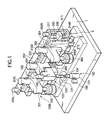
- Fig. 1 is a diagram illustrating a processing section of an eyeglasses lens processing apparatus.
- a sub-base 2 having a lens chuck upper part 100 and lens grinding parts 300R and 300L is fixed on a main base 1.
- a lens-shape measuring section 400 is accommodated in the farther side in the center of the sub-base 2.
- a fixing block 101 which forms a part of the lens chuck upper part 100 is fixed in the center of the sub-base 2, and a DC motor 103 for vertically moving a chuck shaft holder 120 is mounted on top of the fixing block 101.
- the motor 103 rotates a vertically extending feed screw. This rotation causes the holder 120 to move vertically while being guided by a guide rail provided between the holder 120 and the fixing block 101.
- a pulse motor 130 for rotating a chuck shaft 121 is fixed on top of the holder 120.
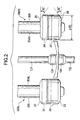
- a lens holder 124 is attached to a lower end of the chuck shaft 121 (see Fig. 2).
- a chuck shaft 152 which forms a part of a lens chuck lower part 150 is rotatably held by a holder 151 which is fixed to the main base 1, and rotation is transmitted thereto by a pulse motor 156.
- a cup receiver 159 for mounting a cup fixed to a lens to be processed is attached to an upper end of the chuck shaft 152 (see Fig. 2).
- the lens grinding parts 300R and 300L are bilaterally symmetrical, and a housing 305 for rotatably holding therein rotating shafts 304R and 304L having a group of abrasive wheels 30 to 36, such as those shown in Fig. 2, is attached to the front portion of each shaft support base 301.
- the rotating shafts 304R and 304L are respectively rotated by servo motors 310R and 310L which are fixed to the respective support bases 301.
- the rough abrasive wheel 30 and the finishing abrasive wheel 31 having a bevel groove are attached to the rotating shaft 304L of the grinding part 300L.
- the chamfering abrasive wheel (corner-portion processing abrasive wheel) 32 for processing a lens front surface and having a conical surface and the chamfering abrasive wheel 33 for processing a lens rear surface and having a conical surface are respectively coaxially attached to an upper end face of the finishing abrasive wheel 31 and a lower end.face of the rough abrasive wheel 30.
- the rough abrasive wheel 30, the polishing abrasive wheel 34 having a bevel groove, the chamfering abrasive wheel 35 for polishing the lens front surface and having a conical surface, and the chamfering abrasive wheel 36 for polishing the lens rear surface and having a conical surface are coaxially attached to. the rotating shaft 304R of the lens grinding part 300R.
- These groups of abrasive wheels use abrasive wheels whose diameters are relatively small at 60 mm or thereabouts so as to improve the processing accuracy and ensure the durability of the abrasive wheels.
- the height of the chamfering surfaces (processing surfaces) of the respective chamfering abrasive wheels 32, 33, 35, and 36 is 5 mm, and the angles of inclination of the chamfering surfaces with respect to the horizontal plane are set to 35 degrees.
- the grinding parts 300R and 300L are respectively movable in the vertical direction and the horizontal direction with respect to the sub-base 2, and their moving mechanisms are arranged as follows:
- the grinding part 300R is fixed to a horizontal slide base 210, and the slide base 210 is horizontally movable along two guide rails 211 fixed to a vertical slide base 201.
- the slide base 201 is vertically movable along two guide rails 202 fixed to the front surface of the sub-base 2.
- a nut block 206 is fixed to the slide base 201, and the slide base 201 moves vertically together with the nut block 206 as a ball screw 205 coupled to a rotating shaft of a pulse motor 204R is rotated.
- the mechanism for horizontally moving the slide base 210 is arranged in the same way as the vertically moving mechanism of the slide base 201, and is actuated by the rotation of a pulse motor 214R.
- the mechanism for moving the grinding part 300L is bilaterally symmetrical with the moving mechanism for the grinding part 300R, and it is vertically moved by a pulse motor 204L and is horizontally moved by a pulse motor 214L (not shown in Fig. 1).
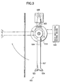
- Fig. 3 is a schematic diagram explaining the lens-shape measuring section 400.
- the measuring section 400 is comprised of a measurement arm 527 having two feelers 523 and 524; a rotating mechanism including a DC motor (not shown) for rotating the arm 527; a sensor plate 510 and photo switches 504 and 505 for detecting the rotation of the arm 527 to control the rotation of the DC motor; a potentiometer 506 for detecting the amount of rotation of the arm 527 to obtain the shapes of the lens front and rear surfaces, and so on. Since the construction of the measuring section 400 is basically identical to that described in JP-A-3-20603 filed by the present assignee, reference may be had to it for details..
- the lens measuring section 400 is moved in the back-and-forth direction (in the direction of the arrow) with respect to the device by a back-and-forth moving means 630, and the amount of its movement is controlled on the basis of radius vector data.
- the arm 527 is rotatingly moved from the lower initial position, and measures the lens edge position by causing the feelers 523 and 524 to abut against the lens front refraction surface and rear refraction surface, respectively.
- a coil spring or the like for canceling the load of the arm 527 in the downward direction is preferably attached to its rotating shaft.
- the measuring section 400 In the measurement of the lens shape (the position of the lens edge), the measuring section 400 is moved back and forth by the back-and-forth moving means 630, and by rotating the lens while causing the feeler 523 to abut against the lens front refractive surface, the shape of the lens front refractive surface is obtained. The feeler 524 is then made to abut against the lens rear refractive surface to obtain its shape.
- the measurement of the lens shape is performed twice at different positions with respect to the radius vector for each of the lens front and rear surfaces. The first measurement is at the position of the radius vector of the target lens shape, and the second measurement is at a position located on an outer side by a predetermined distance from that position of the radius vector. Consequently, angles of inclination of the lens front and rear surfaces are obtained.
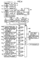
- Fig. 4 is a schematic block diagram illustrating a control system of the apparatus.
- Reference numeral 600 denotes a control unit for effecting the control of the overall apparatus and computation of processing.
- a display unit 10 constituted by a color liquid-crystal display
- an input unit 11 having various operation switches
- the shape measuring section 400 the back-and-forth moving means 630
- various photosensors for detecting the initial positions and the like of the grinding parts 300R and 300L, and so on.
- various motors for movement and rotation are also connected to the control unit 600 via drivers 620 to 628.
- Reference numeral 601 denotes an interface circuit used for transmission and reception of data.
- a lens-frame-shape measuring apparatus 650 Connected to the interface circuit 601 are a lens-frame-shape measuring apparatus 650 (for details of the construction of this apparatus and the measuring operation, refer to JP-A-4-93164 or U.S. Pat. No. 5,333,412, etc.) and a computer 651 for managing the lens processing information.
- Numeral 602 denotes a main program memory in which a program and the like for operating the apparatus are stored
- numeral 603 denotes a data memory for storing inputted data, lens measurement data, and the like.
- edge position data after finishing is determined, and the chamfering data is obtained on the basis of this edge position data.
- a description will be given by citing the lens front surface side after flat finishing as an example.
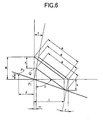
- a cross-sectional shape in the direction of the reference line L3 is considered, as shown in Fig. 6.
- the edge position data on the lens front surface side the data on the target lens shape can be used as it is.
- P1 denotes an edge position which is obtained in the first measurement of the lens edge position measurement
- P2 denotes an edge position (a position located on an outer side by a predetermined distance ⁇ from the position of the first measurement) which is obtained in the second measurement.
- Reference character h denotes the distance between the first measurement position and the second measurement position in the direction of the optical axis of the lens (in the direction of the rotational axis of the lens), and if the inclination of the lens surface is approximately considered as a straight line, its inclination can be determined from ⁇ and h.
- the processing surface is moved in parallel such that the chamfering width e which is equal to the case where both the lens front surface and the lens end face are flat will be obtained, so as to determine an offset correction amount k.
- the correction angle ⁇ of the inclination of the lens edge face is first determined.
- This correction angle ⁇ is determined at respective places in correspondence with the angle of the radius vector.
- the offset correction amount k may be set as follows (in particular, the effect on the correction of the lens front surface side is slight).
- the position in the direction of the optical . axis of the lens of the chamfering point Q using as a reference the edge position P1 on the lens front surface side can be obtained from g - k.
- Processing data on the corner portion can be obtained by determining this correction amount for respective places in correspondence with the angle of the radius vector.
- Processing data on the edge corner portion on the lens rear surface side can be also obtained by a similar method.
- the edge position on the lens rear surface changes due to the correction angle ⁇ of the inclination of the lens end face, as shown in Fig. 8, the cross-sectional shape in the direction of the reference line L3 is considered, and its edge position P3 is determined as follows:
- P1' denotes an edge position which is obtained in the first measurement of the edge position measurement on the lens rear surface side
- P2' denotes an edge position which is similarly obtained in the second measurement on the lens rear surface side.
- ⁇ can be obtained from the results of the first measurement on the lens front surface side and rear surface side. Therefore, if the rear surface curve is approximately considered as a straight line, a correction amount ⁇ in the direction of the optical axis of the lens and a correction amount ⁇ in the radial direction of the lens at the edge position P3 can be obtained as follows:
- edge position data on the rear surface side after finishing can be obtained, and can be used in the calculation of processing data on the edge corner portion on the lens rear surface side as well.
- the target lens shape (eyeglasses frame shape) of the lens to be subjected to facet processing is measured by the frame shape measuring apparatus 650 and is inputted to the apparatus.
- the edge of a dummy lens fitted in the eyeglasses is traced to obtain the target lens shape.
- the data on the target lens shape is inputted from the computer 651.
- a layout screen (not shown) for inputting processing conditions and the position of the optical center with respect to the target lens shape is displayed on the display unit 10.
- Processing conditions including the types of lens material, processing mode, chamfering, and the like are inputted by switches on the input unit 11.
- the mode is set to the flat processing mode, and facet processing is selected for chamfering.
- layout data including FPD (the distance between centers of eyeglasses frame portions), the wearer's pupillary distance (PD), the position (height) of the optical center with respect to the target lens center, and the like is inputted by operating the switches in accordance with input items displayed on the layout screen.
- the lens After the input of the data, the lens is fitted on the chuck shaft 152 side, and a START switch 11i is pressed to start the operation of the apparatus.
- the chuck shaft 121 is then lowered to chuck the lens, and the measuring section 400 is driven to measure the lens shape of the lens front surface and rear surface on the basis of the radius vector information on the target lens shape.
- the measurement of the lens shape is performed twice for each of lens front surface and rear surface at different positions with respect to the radius vector, as described above. Accordingly, the angle of inclination of each of the lens front surface and the lens rear surface is obtained.
- FIG. 9 shows an example of-the screen.
- a figure 701 of the target lens shape showing the appearance and shape of the lens is displayed on the upper side of a screen 700.
- Reference numeral 702 denotes a mark showing the position of the optical center which has been set by the input of the layout.
- Columns for entering data for setting facet processing are provided on the lower side of the screen, and setting data for the lens front surface is inputted in each column of a dotted-line section 710 on the left-hand side of the screen, while setting data for the lens rear surface is inputted in each column of a section 711 on the right-hand side.
- the arrangement provided is such that the edge positions of the target lens shape are designated as two points, i.e. a start point and an end point, so as to set a region to which facet processing is to be applied.
- input columns in a first region 713 to a sixth region 718 are provided in that order from the top.
- a first column 720 from the left is a column for entering a start point (edge position) of the region to be subjected to facet processing
- a second column 721 from the left is a column for entering an end point (edge position) thereof.
- the target lens shape data is arranged to be obtained on.the basis of 1000 points (points obtained by dividing the entire periphery into units of 0.36°), and the start point and the end point are respectively inputted by the number of points with respect to 1000 points.
- the number of points increases counterclockwise by using the horizontal direction as a reference and by using the optical center based on the input of the layout data as the center.
- the start point of the first region is inputted as 330 points, while the end point is inputted as 430 points. If the positions of the start point (S1) and the end point (S2) are inputted with respect to each processing region, lines (a line LS), each connecting the respective two points is displayed on the lens shape figure 701.
- a third column 722 from the left is a column for entering a maximum chamfering width.
- the maximum chamfering width is designated by a value (the value of i in Fig. 6) of the reference line L3, and a setting can be made up to a maximum of 4 mm in the relationship with the width of.the chamfering abrasive wheel, but may be calculated as the values of the offset amount g and chamfering width e in Fig. 6.
- a fourth column 723 from the left is an input column for setting the style of facet processing. As for this processing style, four styles A to D are stored in the memory 602, and a desired one is selected from among them and is inputted.
- a highlighted cursor 730 is first moved by pressing a direction switch 11b on the input unit 11-to select an input column, and the value of each column is set by increasing or decreasing with a "-/+" switch 11c.
- the style of facet processing is consecutively changed over by similarly pressing the switch 11c.
- the input columns of the section 710 for setting the processing of the lens rear surface are also arranged in the same order as that for the lens front surface, so that a description thereof will be omitted. It should be noted that, in the lens shape figure 701, the line LS connecting the two points indicating a processing-designating region on the lens front surface side is displayed in blue color, while the line LS indicating a processing-designating region on the lens rear surface side is displayed in red color, so as to make them visually discernable.
- Figs. 10A and 10B are diagrams for explaining the style A in the form of facet processing.
- the basic of the style A is a form in which an edge corner portion is processed such that the lens surface side after processing forms the straight line LS connecting the start point S1 and the end point S2 designated on the lens edge positions (such that the portion between the two points designated by S1 and S2 is viewed as a straight line), as shown in Fig. 10A.
- the hatched portion becomes an inclined surface where the corner portion is ground by the chamfering abrasive wheel 32 for lens front-surface processing.
- the edge corner portion is processed by that maximum chamfering width.
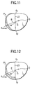
- Fig. 11 is a diagram for explaining the style B. If it is assumed that the straight line connecting the start point S1 and the end point S2 is set as LS, and that the line of the radius vector of the target lens shape using the processing center O as a reference is set as R, the edge position S WMAX is defined in the following manner. The edge position where the length W of its radius vector line R from the edge position to a point of intersection, G, between the straight line LS and the radius vector line R becomes maximum is defined as S WMAX . In the style B, the edge corner portion is processed with the chamfering width gradually made larger from the start point S1 so that the chamfering width becomes maximum at this edge position S WMAX . When the edge position S WMAX has been reached, the edge corner portion is processed so that the chamfering width becomes gradually smaller up to the end point S2.
- Style C is a form in which, in contrast to the above-described style B, the edge corner portion is processed such that the chamfering width is gradually made larger from the start point S1, and after the edge position S WMAX where the chamfering width becomes maximum has been reached, the edge corner portion is processed up to the end point S2 with that maximum chamfering width (see Fig. 12).
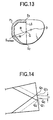
- Style D is a form in which, reversely to the above-described style C, the edge corner portion is processed such,that the chamfering width is gradually made larger from the end point S2, and after the edge position S WMAX where the chamfering width becomes maximum has been reached, the edge corner portion is processed up to the start point S1 with that maximum chamfering width (see Fig. 13).
- style C and the style D are provided so as to be used in combination of the two styles or in combination with the style A.
- the designated processing configuration is corrected so that the portion which is estimated to have the smallest edge thickness after processing does not become smaller than a predetermined length t (e.g., 1 mm).
- t e.g. 1 mm
- Q1 denotes a processing point determined by the calculation of edge corner-portion processing on the lens front surface side
- Q2 denotes a processing point determined by the calculation of edge corner-portion processing on the lens rear surface side. If processing is effected in this state, each processing surface becomes as indicated by the solid line, and the obtained lens shape becomes small in size.
- each processing point Q1' on the lens front surface side is positioned at a position 0.5 mm spaced apart from that central point Q0 toward the front surface side, while a processing point Q2' on the lens rear surface side is similarly positioned at a position 0.5 mm spaced apart from that central point Q0 toward the rear surface side.
- processing is started.
- rough processing is performed.
- the lens grinding parts 300R and 300L are respectively slid to the chuck shaft side of the lens.
- the amounts of movement of the rough abrasive wheels 30 toward the lens side (chuck shaft side) are respectively controlled independently on the basis of rough processing data obtained from the radius vector data.
- control unit 600 performs flat finishing by controlling the height of the flat portion of the finishing abrasive wheel 31 and its movement toward the lens on the basis of the processing data on flat finishing. Upon completion of the finishing process, the operation proceeds to facet processing and the chamfering process for a region for which facet processing is not designated.
- a polishing process for flat finishing is performed by the polishing abrasive wheel 34, and the polishing process of the edge corner portions is subsequently performed by the chamfering abrasive wheel 35 for the polishing process for the front surface and the chamfering abrasive wheel 36 for the polishing process for the rear surface.
- edge corner portions As a cutting tool for effecting the processing of the edge corner portions, it is possible to use an end mill or the like in place of the above-described chamfering abrasive wheels.
- the polishing process may be effected by buffing since it is final finishing.
- an R/L changeover switch 11a on the input unit 11 is pressed to perform the processing of the lens for the left eye.
- the target lens shape data is mirror-inverted between the left and the right.
- the input values for facet processing shown in Fig. 9 are also mirror-inverted between the left and the right. Consequently, the facet processing configuration of the lens for the left eye can be made similar to that of the lens for the right eye.
- the detection of the edge position of the lens may be effected only by the calculation instead of effecting the lens shape measurement.
Landscapes
- Engineering & Computer Science (AREA)
- Mechanical Engineering (AREA)
- Chemical & Material Sciences (AREA)
- Ceramic Engineering (AREA)
- Inorganic Chemistry (AREA)
- Grinding And Polishing Of Tertiary Curved Surfaces And Surfaces With Complex Shapes (AREA)
- Eyeglasses (AREA)
Abstract
Description
Claims (10)
- A lens grinding apparatus for grinding a peripheral edge of an eyeglasses lens, comprising:data input means for inputting data on a target lens shape of an eyeglasses and layout data for layout of the lens with respect to the target lens shape;detecting means for detecting a position of an edge corner portion of the lens after a finishing process on the basis of the data inputted by the data input means;edge corner-portion processing means, having a cutting tool for effecting a facet processing on the edge corner portion of the lens subjected to the finishing process, for processing the lens by relatively moving the cutting tool with respect to a lens holding shaft;region designating means, having display means for displaying a shape of the lens before the facet processing on the basis of the inputted data, for designating a region to be subjected to the facet processing using of the displayed lens shape;selecting means for selecting a facet processing style to be adopted for the designated region of the facet processing from among a plurality of facet processing styles; andcomputing means for obtaining processing data on facet processing on the basis of the selected facet processing style and the position of the edge corner portion in the designated facet processing region.
- The lens grinding apparatus according to claim 1, further comprising:correcting means for correcting the processing data on the basis of the positions of the edge corner portions of a lens front and rear surfaces detected by the detecting means, so that an edge thickness after the facet processing is prevented from becoming smaller than a predetermined width.
- The lens grinding apparatus according to claim 1, wherein the region designating means designates the facet processing region by designating an edge position serving as a start point and an edge position serving as an end point.
- The lens grinding apparatus according to claim 1, wherein the region designating means includes means for designating a maximum processing width of the facet processing region.
- The lens grinding apparatus according to claim 1, wherein the display means displays the designated facet processing region.
- The lens grinding apparatus according to claim 1, wherein the display means displays in different forms the designated facet processing regions on a lens front surface side and a rear surface side.
- The lens grinding apparatus according to claim 1, wherein the region designating means uses data on the facet processing region designated for one of left and right lens shapes to designate the facet processing region for the other one of the left and right lens shapes.
- The lens grinding apparatus according to claim 1, wherein the layout data includes data on a position of an optical center of the lens.
- The lens grinding apparatus according to claim 1, wherein the cutting tool includes an abrasive wheel having a processing surface with a predetermined angle of inclination with respect to a rotating shaft thereof.
- A lens grinding apparatus for grinding a peripheral edge of an eyeglasses lens, comprising:data input means for inputting data on a target lens shape of an eyeglasses and layout data for layout of the lens with respect to the target lens shape;detecting means for detecting a position of an edge corner portion of the lens after a finishing process on the basis of the data inputted by the data input means;edge corner-portion processing means, having a cutting tool for processing the edge corner portion of the lens subjected to the finishing process, for processing the lens by relatively moving the cutting tool with respect to a lens holding shaft;computing means for setting a processing amount of the edge corner portion, and for determining corner-portion processing data after the finishing process on the basis of the set processing amount; andcorrecting means for correcting the processing data on the basis of detected positions of edge corner portions of lens front and rear surfaces, so that the edge thickness after edge corner-portion processing is prevented from becoming smaller than a predetermined width.
Applications Claiming Priority (2)
| Application Number | Priority Date | Filing Date | Title |
|---|---|---|---|
| JP2000321935 | 2000-10-17 | ||
| JP2000321935A JP3990104B2 (en) | 2000-10-17 | 2000-10-17 | Lens grinding machine |
Publications (3)
| Publication Number | Publication Date |
|---|---|
| EP1199134A2 true EP1199134A2 (en) | 2002-04-24 |
| EP1199134A3 EP1199134A3 (en) | 2004-01-28 |
| EP1199134B1 EP1199134B1 (en) | 2006-01-18 |
Family
ID=18799904
Family Applications (1)
| Application Number | Title | Priority Date | Filing Date |
|---|---|---|---|
| EP01124800A Expired - Lifetime EP1199134B1 (en) | 2000-10-17 | 2001-10-17 | Lens grinding apparatus |
Country Status (5)
| Country | Link |
|---|---|
| US (1) | US6641460B2 (en) |
| EP (1) | EP1199134B1 (en) |
| JP (1) | JP3990104B2 (en) |
| DE (1) | DE60116700T2 (en) |
| ES (1) | ES2256136T3 (en) |
Cited By (2)
| Publication number | Priority date | Publication date | Assignee | Title |
|---|---|---|---|---|
| EP1852216A1 (en) | 2006-05-02 | 2007-11-07 | Nidek Co., Ltd | Eyeglass lens processing apparatus |
| EP1852217A3 (en) * | 2006-05-02 | 2008-05-21 | Nidek Co., Ltd | Facetting area setting device and eyeglass lens processing apparatus |
Families Citing this family (11)
| Publication number | Priority date | Publication date | Assignee | Title |
|---|---|---|---|---|
| US7740519B2 (en) | 2003-04-16 | 2010-06-22 | Kabushiki Kaisha Topcon | Method for processing chamfering of eyeglass lens and apparatus for processing the same |
| JP4551162B2 (en) * | 2004-08-31 | 2010-09-22 | 株式会社ニデック | Eyeglass lens processing equipment |
| JP2006189472A (en) * | 2004-12-28 | 2006-07-20 | Nidek Co Ltd | Spectacle lens processing device |
| JP4873878B2 (en) * | 2005-03-31 | 2012-02-08 | 株式会社ニデック | Eyeglass lens peripheral processing equipment |
| JP4841269B2 (en) * | 2006-02-28 | 2011-12-21 | 株式会社ニデック | Eyeglass lens processing equipment |
| JP4959242B2 (en) * | 2006-06-30 | 2012-06-20 | 株式会社ニデック | Eyeglass lens peripheral processing equipment |
| JP5311090B2 (en) * | 2007-12-26 | 2013-10-09 | 東海光学株式会社 | Method for checking target lens and method for displaying outer shape of target lens |
| JP5331464B2 (en) * | 2008-11-28 | 2013-10-30 | 株式会社ニデック | Spectacle lens processing apparatus and spectacle lens processing method |
| JP5469476B2 (en) * | 2010-02-15 | 2014-04-16 | 株式会社ニデック | Eyeglass lens processing equipment |
| JP5745909B2 (en) * | 2011-03-30 | 2015-07-08 | 株式会社ニデック | Eyeglass lens peripheral processing equipment |
| JP7052567B2 (en) | 2018-05-31 | 2022-04-12 | 株式会社ニデック | Eyeglass lens processing control data acquisition device |
Family Cites Families (18)
| Publication number | Priority date | Publication date | Assignee | Title |
|---|---|---|---|---|
| US4503613A (en) * | 1983-03-14 | 1985-03-12 | Textron, Inc. | Method for edge grinding multifaceted lenses |
| WO1988004974A1 (en) * | 1987-01-12 | 1988-07-14 | Hoya Corporation | Method and apparatus for processing circumference of spectacle lens |
| JP2761590B2 (en) * | 1989-02-07 | 1998-06-04 | 株式会社ニデック | Eyeglass lens grinding machine |
| US5053971A (en) * | 1989-08-30 | 1991-10-01 | Gerber Optical, Inc. | Method and apparatus for edging an optical lens |
| US5148637A (en) * | 1990-02-27 | 1992-09-22 | Bausch & Lomb Incorporated | Lens edging system with programmable feed and speed control |
| JP2925685B2 (en) | 1990-08-02 | 1999-07-28 | 株式会社ニデック | Frame shape measuring device |
| US5333412A (en) * | 1990-08-09 | 1994-08-02 | Nidek Co., Ltd. | Apparatus for and method of obtaining processing information for fitting lenses in eyeglasses frame and eyeglasses grinding machine |
| JP2918657B2 (en) * | 1990-08-09 | 1999-07-12 | 株式会社ニデック | Eyeglass lens grinding machine |
| JP2907974B2 (en) | 1990-08-28 | 1999-06-21 | 株式会社ニデック | Eyeglass frame tracing device |
| FR2682628B1 (en) * | 1991-10-21 | 1996-01-05 | Buchmann Optical Eng | IMPROVEMENTS IN GRINDING AND BEVELING MACHINES FOR OPHTHALMIC LENSES. |
| US5257198A (en) * | 1991-12-18 | 1993-10-26 | Schoyck Carol G Van | Method of transmitting edger information to a remote numerically controlled edger |
| JP3011526B2 (en) | 1992-02-04 | 2000-02-21 | 株式会社ニデック | Lens peripheral processing machine and lens peripheral processing method |
| DE4414784C2 (en) * | 1994-04-28 | 1996-07-18 | Wernicke & Co Gmbh | System for grinding the peripheral edge and / or an optical surface of spectacle lenses |
| DE19527222C2 (en) * | 1995-07-26 | 1997-09-04 | Wernicke & Co Gmbh | System for grinding at least the peripheral edge of spectacle lenses and method for mathematically taking into account the position of a spectacle lens blank held on a holding head of the system |
| JP4011134B2 (en) * | 1996-03-26 | 2007-11-21 | 株式会社ニデック | Lens grinding machine |
| JP3667483B2 (en) | 1997-02-10 | 2005-07-06 | 株式会社ニデック | Lens grinding machine |
| JP4002324B2 (en) | 1997-07-08 | 2007-10-31 | 株式会社ニデック | Lens grinding device |
| JP3730406B2 (en) * | 1998-04-30 | 2006-01-05 | 株式会社ニデック | Eyeglass lens processing equipment |
-
2000
- 2000-10-17 JP JP2000321935A patent/JP3990104B2/en not_active Expired - Fee Related
-
2001
- 2001-10-17 DE DE60116700T patent/DE60116700T2/en not_active Expired - Lifetime
- 2001-10-17 ES ES01124800T patent/ES2256136T3/en not_active Expired - Lifetime
- 2001-10-17 EP EP01124800A patent/EP1199134B1/en not_active Expired - Lifetime
- 2001-10-17 US US09/978,078 patent/US6641460B2/en not_active Expired - Lifetime
Cited By (3)
| Publication number | Priority date | Publication date | Assignee | Title |
|---|---|---|---|---|
| EP1852216A1 (en) | 2006-05-02 | 2007-11-07 | Nidek Co., Ltd | Eyeglass lens processing apparatus |
| EP1852217A3 (en) * | 2006-05-02 | 2008-05-21 | Nidek Co., Ltd | Facetting area setting device and eyeglass lens processing apparatus |
| US7510459B2 (en) | 2006-05-02 | 2009-03-31 | Nidek Co., Ltd. | Eyeglass lens processing apparatus |
Also Published As
| Publication number | Publication date |
|---|---|
| US20020072299A1 (en) | 2002-06-13 |
| JP2002126983A (en) | 2002-05-08 |
| EP1199134B1 (en) | 2006-01-18 |
| ES2256136T3 (en) | 2006-07-16 |
| US6641460B2 (en) | 2003-11-04 |
| DE60116700D1 (en) | 2006-04-06 |
| EP1199134A3 (en) | 2004-01-28 |
| DE60116700T2 (en) | 2006-08-03 |
| JP3990104B2 (en) | 2007-10-10 |
Similar Documents
| Publication | Publication Date | Title |
|---|---|---|
| EP0857540B1 (en) | Lens grinding apparatus | |
| JP3730406B2 (en) | Eyeglass lens processing equipment | |
| KR101456301B1 (en) | Glasses lens processing equipment | |
| JP4002324B2 (en) | Lens grinding device | |
| KR101487018B1 (en) | Eyeglass lens grinding machine | |
| KR101363184B1 (en) | Eyeglass lens processing method and eyeglass lens processing apparatus | |
| EP1199134B1 (en) | Lens grinding apparatus | |
| EP1938923B1 (en) | Method of grinding eyeglass lens, and eyeglass lens grinding apparatus | |
| US7840294B2 (en) | Layout setting device for processing eyeglass lens, eyeglass lens processing apparatus, eyeglass frame measuring device and cup attaching device, each having the same | |
| KR101516434B1 (en) | Apparatus for processing eyeglass lens | |
| KR101415475B1 (en) | Eyeglass lens processing apparatus | |
| JP4397367B2 (en) | Lens grinding machine | |
| JP3774529B2 (en) | Lens grinding machine | |
| KR101437160B1 (en) | Glasses lens processing equipment | |
| EP0857539B1 (en) | Lens grinding apparatus | |
| KR101415449B1 (en) | Setting apparatus for facet processing area and eyeglass lens processing apparatus therewith | |
| JP7721970B2 (en) | BEVE FORMING DATA SETTING DEVICE, EYEWEAR LENS PROCESSING DEVICE, AND BEVE FORMING DATA SETTING PROGRAM | |
| JPH11216651A (en) | Eyeglass lens grinding apparatus | |
| JPH10225854A (en) | Lens grinding work device | |
| JP3679236B2 (en) | Eyeglass lens grinding device | |
| JP4036942B2 (en) | Eyeglass lens grinding device |
Legal Events
| Date | Code | Title | Description |
|---|---|---|---|
| PUAI | Public reference made under article 153(3) epc to a published international application that has entered the european phase |
Free format text: ORIGINAL CODE: 0009012 |
|
| AK | Designated contracting states |
Kind code of ref document: A2 Designated state(s): AT BE CH CY DE DK ES FI FR GB GR IE IT LI LU MC NL PT SE TR |
|
| AX | Request for extension of the european patent |
Free format text: AL;LT;LV;MK;RO;SI |
|
| PUAL | Search report despatched |
Free format text: ORIGINAL CODE: 0009013 |
|
| AK | Designated contracting states |
Kind code of ref document: A3 Designated state(s): AT BE CH CY DE DK ES FI FR GB GR IE IT LI LU MC NL PT SE TR |
|
| AX | Request for extension of the european patent |
Extension state: AL LT LV MK RO SI |
|
| 17P | Request for examination filed |
Effective date: 20040528 |
|
| 17Q | First examination report despatched |
Effective date: 20040806 |
|
| AKX | Designation fees paid |
Designated state(s): DE ES FR GB |
|
| GRAP | Despatch of communication of intention to grant a patent |
Free format text: ORIGINAL CODE: EPIDOSNIGR1 |
|
| GRAS | Grant fee paid |
Free format text: ORIGINAL CODE: EPIDOSNIGR3 |
|
| GRAA | (expected) grant |
Free format text: ORIGINAL CODE: 0009210 |
|
| AK | Designated contracting states |
Kind code of ref document: B1 Designated state(s): DE ES FR GB |
|
| REG | Reference to a national code |
Ref country code: GB Ref legal event code: FG4D |
|
| REF | Corresponds to: |
Ref document number: 60116700 Country of ref document: DE Date of ref document: 20060406 Kind code of ref document: P |
|
| REG | Reference to a national code |
Ref country code: ES Ref legal event code: FG2A Ref document number: 2256136 Country of ref document: ES Kind code of ref document: T3 |
|
| ET | Fr: translation filed | ||
| PLBE | No opposition filed within time limit |
Free format text: ORIGINAL CODE: 0009261 |
|
| STAA | Information on the status of an ep patent application or granted ep patent |
Free format text: STATUS: NO OPPOSITION FILED WITHIN TIME LIMIT |
|
| 26N | No opposition filed |
Effective date: 20061019 |
|
| PGFP | Annual fee paid to national office [announced via postgrant information from national office to epo] |
Ref country code: ES Payment date: 20121019 Year of fee payment: 12 |
|
| REG | Reference to a national code |
Ref country code: ES Ref legal event code: FD2A Effective date: 20141107 |
|
| PG25 | Lapsed in a contracting state [announced via postgrant information from national office to epo] |
Ref country code: ES Free format text: LAPSE BECAUSE OF NON-PAYMENT OF DUE FEES Effective date: 20131018 |
|
| REG | Reference to a national code |
Ref country code: FR Ref legal event code: PLFP Year of fee payment: 16 |
|
| PGFP | Annual fee paid to national office [announced via postgrant information from national office to epo] |
Ref country code: DE Payment date: 20161011 Year of fee payment: 16 Ref country code: GB Payment date: 20161012 Year of fee payment: 16 |
|
| REG | Reference to a national code |
Ref country code: FR Ref legal event code: PLFP Year of fee payment: 17 |
|
| REG | Reference to a national code |
Ref country code: DE Ref legal event code: R119 Ref document number: 60116700 Country of ref document: DE |
|
| GBPC | Gb: european patent ceased through non-payment of renewal fee |
Effective date: 20171017 |
|
| PG25 | Lapsed in a contracting state [announced via postgrant information from national office to epo] |
Ref country code: DE Free format text: LAPSE BECAUSE OF NON-PAYMENT OF DUE FEES Effective date: 20180501 Ref country code: GB Free format text: LAPSE BECAUSE OF NON-PAYMENT OF DUE FEES Effective date: 20171017 |
|
| REG | Reference to a national code |
Ref country code: FR Ref legal event code: PLFP Year of fee payment: 18 |
|
| PGFP | Annual fee paid to national office [announced via postgrant information from national office to epo] |
Ref country code: FR Payment date: 20190913 Year of fee payment: 19 |
|
| PG25 | Lapsed in a contracting state [announced via postgrant information from national office to epo] |
Ref country code: FR Free format text: LAPSE BECAUSE OF NON-PAYMENT OF DUE FEES Effective date: 20201031 |