EP1199105A1 - Dispositif de moussage - Google Patents
Dispositif de moussage Download PDFInfo
- Publication number
- EP1199105A1 EP1199105A1 EP01830472A EP01830472A EP1199105A1 EP 1199105 A1 EP1199105 A1 EP 1199105A1 EP 01830472 A EP01830472 A EP 01830472A EP 01830472 A EP01830472 A EP 01830472A EP 1199105 A1 EP1199105 A1 EP 1199105A1
- Authority
- EP
- European Patent Office
- Prior art keywords
- liquid
- air
- chamber
- tank
- valve
- Prior art date
- Legal status (The legal status is an assumption and is not a legal conclusion. Google has not performed a legal analysis and makes no representation as to the accuracy of the status listed.)
- Granted
Links
Images


Classifications
-
- B—PERFORMING OPERATIONS; TRANSPORTING
- B05—SPRAYING OR ATOMISING IN GENERAL; APPLYING FLUENT MATERIALS TO SURFACES, IN GENERAL
- B05B—SPRAYING APPARATUS; ATOMISING APPARATUS; NOZZLES
- B05B7/00—Spraying apparatus for discharge of liquids or other fluent materials from two or more sources, e.g. of liquid and air, of powder and gas
- B05B7/0018—Spraying apparatus for discharge of liquids or other fluent materials from two or more sources, e.g. of liquid and air, of powder and gas with devices for making foam
- B05B7/0025—Spraying apparatus for discharge of liquids or other fluent materials from two or more sources, e.g. of liquid and air, of powder and gas with devices for making foam with a compressed gas supply
- B05B7/0031—Spraying apparatus for discharge of liquids or other fluent materials from two or more sources, e.g. of liquid and air, of powder and gas with devices for making foam with a compressed gas supply with disturbing means promoting mixing, e.g. balls, crowns
- B05B7/0037—Spraying apparatus for discharge of liquids or other fluent materials from two or more sources, e.g. of liquid and air, of powder and gas with devices for making foam with a compressed gas supply with disturbing means promoting mixing, e.g. balls, crowns including sieves, porous members or the like
-
- B—PERFORMING OPERATIONS; TRANSPORTING
- B05—SPRAYING OR ATOMISING IN GENERAL; APPLYING FLUENT MATERIALS TO SURFACES, IN GENERAL
- B05B—SPRAYING APPARATUS; ATOMISING APPARATUS; NOZZLES
- B05B11/00—Single-unit hand-held apparatus in which flow of contents is produced by the muscular force of the operator at the moment of use
- B05B11/01—Single-unit hand-held apparatus in which flow of contents is produced by the muscular force of the operator at the moment of use characterised by the means producing the flow
- B05B11/10—Pump arrangements for transferring the contents from the container to a pump chamber by a sucking effect and forcing the contents out through the dispensing nozzle
- B05B11/1001—Piston pumps
- B05B11/1004—Piston pumps comprising a movable cylinder and a stationary piston
-
- B—PERFORMING OPERATIONS; TRANSPORTING
- B05—SPRAYING OR ATOMISING IN GENERAL; APPLYING FLUENT MATERIALS TO SURFACES, IN GENERAL
- B05B—SPRAYING APPARATUS; ATOMISING APPARATUS; NOZZLES
- B05B11/00—Single-unit hand-held apparatus in which flow of contents is produced by the muscular force of the operator at the moment of use
- B05B11/01—Single-unit hand-held apparatus in which flow of contents is produced by the muscular force of the operator at the moment of use characterised by the means producing the flow
- B05B11/10—Pump arrangements for transferring the contents from the container to a pump chamber by a sucking effect and forcing the contents out through the dispensing nozzle
- B05B11/1087—Combination of liquid and air pumps
Definitions
- the present invention relates to a foaming device capable of generating foam by mixing a quantity of liquid with a volume of air, in accordance with the preamble of Claim 1.
- rate of flow of air means the variation in the volume of air expelled as a function of the displacement of an air piston which deforms (compresses) the chamber in which the air to be expelled is contained.
- the above solution has the disadvantage of expelling an airflow that does not completely mix with the liquid. In other words, at the beginning of the compression of the device, the airflow that invests the liquid is too great for the available liquid.
- the present invention addresses the problem of devising a foaming device that has structural and functional characteristics such as to satisfy the abovementioned requirements and at the same time obviate the problems discussed with reference to the prior art.
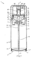
- Figure 1 shows a cross section through a foaming device fitted to a tank and with a cap
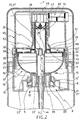
- Figure 2 shows an enlarged cross section through the foaming device of Figure 1;
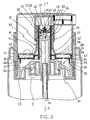
- Figure 3 shows an enlarged cross section through the foaming device of Figure 1 when deformed at maximum compression
- Figure 4 shows detail A from the device of Figure 3, enlarged and in a deformed condition assumed during expulsion of air;
- Figure 5 shows detail B from the device of Figure 3, enlarged and in a deformed condition during aspiration of air;
- Figure 6 shows detail C from the device of Figure 3, enlarged and in a deformed condition during aspiration of air;
- Figure 7 shows an enlarged perspective view of a foaming member
- Figure 8 shows a cross section through another embodiment of the foaming device, fitted to the tank and with the cap, and
- Figure 9 is a graph showing the reduction in the volume of an air chamber of the foaming device of Figure 1 or Figure 8 against the stroke of an air piston of the said device.
- the number 1 refers to a foaming device capable of generating foam by mixing a volume of air A' with a quantity of liquid L'.
- the device 1 can be fitted to a tank 2 designed to contain the liquid L during transportation and during use of the device 1, thus ensuring that it is not lost or contaminated with dust or the like.
- the tank 2 is bounded by essentially cylindrical side walls 3 that extend along an axis of symmetry X-X, from an upper end 3' to a lower end 3''. At the said lower end 3'', the tank 2 is provided with a bottom 4, while at the upper end 3' it is provided with closing means 5.
- the bottom 4 of deformable resilient material, is fitted removably to the tank 2 and is roughly dish-shaped.
- the said bottom 4 also includes a gripping lip 4' in the form of a cylindrical wall which, together with the outermost wall of the bottom 4, provides a gripping space 4''.
- an aspiration tube 6 Near the bottom 4, on the inside of the tank, is one end of an aspiration tube 6, the other end of which fits inside an aperture 7 formed in the closing means 5 of the tank 2.
- the closing means 5 comprise a base 8 shaped as a series of vertical cylindrical walls 8' and annuluses 8'' which give it a conical profile.
- the base 8 is pierced by a plurality of holes 9 that allow communication between the tank 2 and the external environment via a renewing pass 10 (in Figure 2) whereby the air in the tank 2 is renewed.
- the closing means 5 also include a containment cylinder 11 integral with the base 8 and forming one piece with the side wall 3 of the tank 2, to which it is connected by a shoulder surface 12 of curvilinear sections. Internally, the said containment cylinder 11 has an essentially annular stop edge 17.
- shoulder surface 12 meets the side walls 3 of the tank it forms a supporting ledge 13 to support a cap 14, which can be placed on the device 1 when the said device 1 is not likely to be used.
- the containment cylinder 11 forms a space 15 that houses an envelope 16 attached to it by male/female attachment to the base 8 of the closing means 5 of the tank 2.
- Attachment of the envelope 16 to the base 8 is via an annular base 19 with an undercut portion 20 engaged with the series of vertical cylindrical walls 8' and annuluses 8'' of the base 8 of the closing means 5.
- the said annular base 19 and the said undercut portion 20, and also the series of vertical cylindrical walls 8' and annuluses 8'', represent a preferred embodiment of means of attachment.
- the annular base 19 terminates, in a preferred embodiment of the device 1, in an annular lip 21 which diverges downwards and engages, deforming elastically as it does so, with an annular cavity defined by the series of vertical cylindrical walls 8' and annuluses 8'' of the closing means 5.
- the annular lip 21 forms, in a preferred embodiment, a renewing valve 21' through which the air in the tank is renewed.
- the said renewing valve 21' for the renewal of air in the tank is a non-limiting example of an embodiment of the means of renewing the air in the tank.
- the envelope 16 also includes a resiliently deformable diaphragm 22, preferably cup-shaped, which encloses an air chamber 23, and a tubular core 26, which houses one end of the aspiration tube 6 and is integral with and concentric with the diaphragm 22.
- the diaphragm 22 preferably comprises a supporting surface 22' whose shape is essentially that of a flat circular annulus, and a surface 22'' which is concave towards the air chamber.
- the concave surface 22'' of the diaphragm 22 is provided with an anchoring ring 24 on the outside edge and an inner ledge 25 not far from the inside edge of the diaphragm 22.
- the tubular core 26 is surmounted by a cup-shaped head 27 that acts as a piston 27' for the liquid: said head has a sealing lip 28 with diverging walls and an essentially frustoconical projection 29.
- the projection 29 contains a cut 30 approximately at right angles to an axis Y-Y of symmetry of the tubular core, which preferably coincides with the axis X-X of symmetry of the tank.
- the closing lip 47 acts as a non-return valve 46 on a path of aspiration of the liquid 44 that allows communication between the tank 2 and a liquid chamber 42.
- the cup-shaped head 27 of the envelope 16 is functionally connected with an intermediate element 31 comprising an annular band 32 and a liquid cylinder 33, these being preferably made in one piece.
- the annular band 32 of the intermediate element 31 comprises, in a preferred embodiment, a first annulus 32' and, concentric and integral with the first annulus 32', a second annulus 32''.
- the annuluses are arranged on parallel planes at different heights.
- the second annulus 32'' comprises, in another embodiment of the device, an upper annular projection 40 and a lower annular projection 41.
- the said projections run around the edge of the second annulus 32'', the first above and the second below the said second annulus.
- the lower projection 41 engages with the inside ledge 25 of the diaphragm 22.
- the said annular band 32 of the intermediate element 31 provides an annular space 34 bounded by the first annulus 31', the second annulus 32'' and the upper annular projection 40.
- the annular band 32 contains a plurality of holes 35 for expulsion of the volume of air A' (in Figure 4), these preferably being in the first annulus 32' and allowing communication between the air chamber 23 and a path of expulsion of the air 36 into a mixing chamber 37 in which the volume of air A' is mixed with the quantity of liquid L'.
- annular band 32 contains a plurality of air aspiration holes 38 (in Figure 5), preferably in the second annulus 32'', so that an air aspiration path 39 can communicate with the air chamber 23.
- the liquid cylinder 33 contains the liquid chamber 42. This is separated from the air chamber 23 by the sealing lip 28 of the envelope 16 which presses against the walls of the liquid cylinder 33.
- the liquid chamber 42 is preferably bounded not only by the liquid cylinder 33 and cup-shaped head 27 but also by a transverse expulsion wall 43 at one end of the liquid cylinder 33.
- the cut 30 in the cup-shaped head 27 gives communication between the liquid chamber 42 and the space inside the tubular core 26 of the envelope, through the liquid aspiration path 44.
- a non-return valve 46 is positioned on the liquid aspiration path 44.
- the said non-return valve 46 is produced, in a preferred form of the device 1, by a flexible lip 47 belonging to the cup-shaped head 27 and positioned above the cut 30 and integral with the frustoconical projection 29.
- the non-return valve 46 is only a preferred, non-limiting example of means of controlling the flow of liquid during expulsion.
- the transverse expulsion wall 43 of the liquid cylinder 33 is preferably pierced by a plurality of holes 48 for expulsion of the liquid and defines, together with a portion of the liquid cylinder 33, a liquid expulsion chamber 49.
- the liquid chamber 42 is in communication, via the liquid expulsion holes 48 and a liquid expulsion path 50, with the mixing chamber 37.
- the liquid expulsion path 50 is separated from the air expulsion path 36 by the liquid cylinder 33, as far as the mixing chamber 37 where the said paths come together.
- a liquid expulsion valve 51 is positioned on the liquid expulsion path 50.
- the said liquid expulsion valve 51 is preferably a resiliently deformable flap 52 which is housed in the expulsion chamber 49 and provided with elongate walls 52' which press and deform against the walls of the expulsion chamber 49.
- the liquid expulsion valve 51 described is a preferred, non-limiting example of an embodiment of means of sealing the foam.
- the intermediate element 31 is attached to an essentially hollow air piston 53 comprising a upper cylindrical body 54 and a lower cylindrical body 54, the diameter of the latter being greater than that of the upper cylindrical body 54, and these two bodies 54 and 55 being joined by an annular surface 56.
- the said upper cylindrical body 54 is preferably joined to the said annular surface 56 by a frustoconical wall 57.
- the air piston 53 slides inside and is connected to the containment cylinder 11 by means of a guide projection 58 on the lower cylindrical body 55, on the outside of the latter, which abuts against the stop edge 17 of the containment cylinder 11.
- the lower cylindrical body 55 preferably comprises an annular tooth 59 located on the inside of the said lower cylindrical body in abutment with the anchoring ring 24 of the diaphragm 22.
- the diaphragm 22 is locked, near its edge, between the intermediate element 31 and the air piston 53, by the annular tooth 59 on the air piston 53 in abutment against the anchoring ring 24 of the diaphragm 22, and by the lower annular projection 41 of the intermediate element in abutment against the ledge 25 on the inside of the diaphragm 22.
- the annular surface 56 of the air piston 53 comprises a plurality of essentially radial grooves 60 running from the periphery towards the centre of the said annular surface and interrupted at a plurality of through holes 61 passing through the said annular band.
- the through holes 61 (shown in Figure 5), located on the air aspiration path 39, are intercepted by an air aspiration valve 62, which is typically a second annular portion 63'' of a resiliently deformable ring 63.
- the said ring 63 also includes a first annular portion 63', which intercepts the air expulsion holes 35.
- the first portion 63' of the ring 63 acts as an air expulsion valve 64.
- the air aspiration valve 62 and the air expulsion valve 64 represent a preferred, non-limiting embodiment, the first as a means of controlling the incoming flow of air and the second as a means of controlling the outgoing flow of air.
- the air piston 53 is surmounted, in another embodiment of the device 1, by an essentially hollow head 65 comprising, as a minimum, an outer cylindrical wall 66, an inner cylindrical wall 67 (these walls 66 and 67 being preferably concentric), and a transverse pipe 68 that extends essentially at right angles to the axis Y-Y.
- the said head 65 is connected to the upper cylindrical body 54 of the air piston 53 by attaching together the upper cylindrical body 54 of the air piston 53 and the inner cylindrical wall 67 of the head 65.
- the outer cylindrical wall 66 of the head 65 extends down and rests on the annular surface 56 of the air piston 53.
- the transverse pipe 68 inside the head 65 can receive a foaming member 69 ( Figure 7) comprising a grid 70 with a plurality of passageways 71 dividing the foaming member 69 into an upper zone 72 and a lower zone 73, the said passageways 71 being such as to allow communication between the said upper zone and the said lower zone.
- the foaming member 69 also includes one or more bases 74, each provided with an aperture 75 entirely contained either within the upper zone 72 or within the lower zone 73 of the said foaming member 69.
- the foaming member 69 includes one or more intermediate projections 76 entirely contained either within the upper zone 72 or within the lower zone 73 of the foaming member 69.
- the intermediate projection 76 and the transverse pipe 68 define a labyrinth path 77 that passes through the grid at at least two points followed by the quantity of liquid L' mixed with the volume of air A' for complete and uniform generation of the foam.
- the device 1 according to the invention is capable of generating foam by mixing the volume of air A' with the quantity of liquid L'.
- the head 65 In the initial or rest configuration of the device 1, illustrated in Figure 2, the head 65 is in the fully up position in which it is supported by the air piston 53.
- the device 1 is permanently being pushed towards the said initial or rest configuration by the diaphragm 22, which is of a resilient material.
- the said diaphragm 22 exerts a force which, in the initial or rest configuration, pushes the guide projection 58 of the lower cylindrical body 55 towards the stop edge 17 of the containment cylinder 11, supporting the air piston 53 in an upper limit position.
- the said diaphragm 22 is preferably elastically preloaded, even with the air piston 53 in the said upper limit position.
- the air chamber 23 contains the volume of air A', while the liquid chamber 42 does not contain the quantity of liquid L', which must first be drawn up from the tank 2.
- the head 65 connected to the air piston 53 moves the said air piston down, in a direction roughly parallel to the axis Y-Y and/or X-X, guided by the containment cylinder 11.
- the air piston can be moved from the upper limit position, described above, to a lower limit position, in which the lower cylindrical body 55 interferes with the base 8 of the closing means 5.
- the air piston 53 also takes down with it the intermediate element 31 which, together with the air piston 53, anchors the edge of the diaphragm 22.
- the effect of the cup-shaped diaphragm 22 is to return the device 1 to the initial or rest configuration, following the phases of aspiration of the liquid from the tank 2 into the liquid chamber 42 and of aspiration of air from the environment around the outside of the device 1 into the air chamber 23.
- the elastic force of the diaphragm 22 acts on the air piston 53, pushing it upwards and tending to increase the volume of the deformed air chamber 23 and the volume of the liquid chamber 42.
- the diaphragm 22 acts as elastic means in a preferred and non-limiting embodiment of the device 1.
- the tendency to increase the volume of the deformed air chamber 23 and the volume of the liquid chamber 42 generates a depression in the air chamber 23 and a depression in the liquid chamber 42.
- the depression in the liquid chamber 42 closes the liquid expulsion valve 51, preventing communication between the liquid chamber 42 and the liquid expulsion path 50, and opens the non-return valve 46, allowing communication between the liquid chamber 42 and the tank 2, via the liquid aspiration path 44.
- the depression in the liquid chamber 42 lifts the closing lip 47 of the frustoconical projection 29, which lies over the cut 30, off the said cut 30, giving communication between the liquid chamber 42 and the liquid aspiration path 44, allowing liquid to be drawn from the tank 2 into the liquid chamber 42.
- the liquid chamber 42 gradually fills with liquid until it contains a quantity of liquid L' sufficient to generate the foam.
- Depressing the head 65 depresses the air piston 53, which moves the intermediate element 31.
- the intermediate element 31 and the air piston 53 clamp the edge of the diaphragm 22 so that the said diaphragm 22 can deform.
- the diaphragm 22 deforms. This initially affects that portion of the concave surface 22'' of the diaphragm 22 which is next to the supporting surface 22'.
- the change in the volume of the air chamber 23 is less than the change in the volume of the said air chamber later on in the deformation, when deformation occurs to portions of the concave surface 22'' progressively further away from the supporting surface 22' of the diaphragm 22.
- R of flow of expelled air here means the variation in the volume of air expelled as a function of the downward displacement of the air piston. Consequently the straight line R in Figure 9 describes the change in the volume of air expelled by a device with a constant rate of flow of air and the increasing curve S, characteristic of the foaming device 1 according to the invention, describes the change in the volume of air expelled by a device with an increasing rate of flow of air.
- the diaphragm 22 deforms elastically under the action of the air piston 53, compressing the air inside the air chamber 23, increasing the pressure of the air in the air chamber 23.
- the increased air pressure in the air chamber 23 produces an increased air pressure in the annular space 34 connected to the air chamber 23 through the air aspiration holes 38. This closes the air aspiration valve.
- the increased air pressure in the space 15 exerts a force on the second portion 63'' of the elastic ring 63 against the annular surface 56 of the air piston 53, covering and closing the through holes 61.
- the increased pressure of the air in the air chamber 23 opens the air expulsion valve 64, expelling the volume of air A' into the mixing chamber 37 via the air expulsion path 36.
- the increased air pressure in the chamber 23 produces a force on the first portion 63' of the elastic ring 63, which deforms elastically away from the first annulus 32' of the annular band 32 of the intermediate element 31, assisted by the space left vacant by the frustoconical wall 57 of the air piston 53.
- the convex surface 22'' of the diaphragm deforms under the action of the air piston 53 and progressively drapes itself over the base 8 of the closing means 5, shaped generally conically.
- the convex surface 22'' of the diaphragm 22 interferes with the vertical cylindrical walls 8' and the annuluses 8'' of the base 8, which guide the said convex surface as it deforms.
- the convex surface 22'' of the diaphragm 22 is received progressively in recesses 15' of the space 15 between successive vertical cylindrical walls 8'.
- the series of vertical cylindrical walls 8' and annuluses 8'' - and also the recesses 15' in the space 15, shaped so as to receive, in the deformed configuration of the device, the diaphragm 22 or portions of this diaphragm such as the convex surface 22'' - represent a preferred and non-limiting embodiment of means for increasing the rate of flow of expelled air.
- the intermediate element 31 slides relative to the liquid piston 27', which remains in a fixed position with respect to the tank 2, reducing the volume of the liquid chamber 42 and increasing the pressure of the liquid in the liquid chamber 42.
- the sealing lip 28 of the tubular core 26 stays pressed against the walls of the liquid cylinder 33.
- the liquid passes through the liquid expulsion holes 48 into the expulsion chamber 49 and the increased pressure of the liquid in the liquid chamber 42 generates an increase in the pressure of the liquid in the expulsion chamber 49.
- the increase of the pressure of the liquid in the expulsion chamber 49 opens the liquid expulsion valve 51. In other words, the increase in the pressure of the liquid in the expulsion chamber generates a force which lifts the elongate walls 52' of the flap 52 off the walls of the expulsion chamber, allowing the liquid to reach the mixing chamber 37.
- the increased pressure of the liquid in the liquid chamber 42 closes the non-return valve 46.
- the increased pressure of the liquid elastically deforms the closing lip 47 of the frustoconical projection 29, closing the cut 30 and preventing communication between the liquid aspiration path 44 and the liquid chamber 42.
- the quantity of liquid L' and the volume of air A' pass along the liquid expulsion path 50 and the air expulsion path 35, respectively, remaining unmixed until they reach the mixing chamber 37, in which the liquid expulsion path 50 and air expulsion path 35 come together.
- the movement of the air and liquid through the foaming member 69 generates the foam which escapes into the environment outside the device 1 through the transverse pipe 68.
- the volume of air A' and the quantity of liquid L' mix intimately along a labyrinth path 77 in which they cross the grid 70 with its passageways 71 one or more times.
- the device 1 When the head 65 is released, the device 1 returns to the initial or rest configuration, following aspiration of liquid from the tank 2 and aspiration of air from the environment outside the device into the air chamber 23.
- the elastic force of the deformed diaphragm 22 pushes the air piston 53 upwards, tending to increase the volume of the air chamber 23 and of the liquid chamber 42.
- the tendency to increase the volume of the air chamber 23 generates a depression of the air in this chamber.
- the depression of the air in the air chamber 23 opens the air aspiration valve 62, allowing communication between the environment outside the device and the air chamber 23 via the air aspiration path 39.
- the depression of the air in the air chamber 23 lifts the second portion 63'' of the elastic ring 63 off the annular surface 56 of the air piston 53 and uncovers the through holes 61.
- the second portion 63'' of the elastic ring 63 deforms and is received in the annular space 34 of the intermediate element 31.
- the depression of the air in the air chamber 23 closes the air expulsion valve 64 and prevents communication between the air mixing chamber 37 and the air chamber 23 via the air expulsion path 36.
- the depression of the air in the air chamber 23 presses the first portion 63' of the elastic ring 63 against the first annulus 32' of the intermediate element 31, closing the air expulsion holes 35.
- the depression inside the liquid chamber 42 is transmitted to the expulsion chamber 49, which closes the liquid expulsion valve 51 and prevents communication between the liquid chamber 42 and the mixing chamber 37, via the liquid expulsion path 50.
- the elongate walls 52' of the flap 52 press against the walls of the expulsion chamber 49 and prevent communication between the liquid chamber 42 and the liquid expulsion path 50.
- the flap 52 with its elongate side walls 52' is a preferred and non-limiting embodiment of means of sealing the foam.
- the depression in the tank 2 lifts the annular lip 21 of the annular base 19 of the envelope 16 off one of the vertical cylindrical walls 8' of the base 8 of the closing means 5, allowing communication between the tank 2 and the environment outside the device 1 via the air renewal holes 9 and the air renewal path 10.
- the rate of flow of air when the diaphragm 22 first begins to deform is small enough for it to remain completely trapped by the liquid.
- the rate of flow of expelled air increases with displacement of the air piston, and continues to be sufficient for foam generation.
- the device 1 according to the invention is able to expel practically the whole of the volume of air A' present in the air chamber 23 when the latter is in its initial or rest configuration.
- the device 1 exhibits the advantage of possessing a simplified structure which facilitates manufacture of the device and improves the operations of assembly of its component parts.
- the device 1 consists of a small number of components but still generates foam effectively.
- the device 1 according to the invention is not subject to deterioration of its parts by the action of chemical attack on metal parts and such like by the foam-generating liquid employed.
- the structure of the device 1 avoids the contamination of the air chamber during use of the device with residues of liquid or previously formed foam and, at the same time, avoids contamination of the tank with foam. Additionally, no liquid is entrained outwards during use of the device or during transport.
- the structure of the device 1 makes the assembly rigid, in such a way that there is no looseness in the connections between the parts.
- the cup-shaped head 27 of the tubular core 26 of the envelope 16 receives a moving part 90 capable of moving between a configuration of abutment against the tubular core 26 and a raised configuration in abutment against an end stop 91 on the cup-shaped head 27.
- the non-return valve 46 comprises, in the other embodiment of the device 1, the end stop 91 and the moving part 90.
Landscapes
- External Artificial Organs (AREA)
- Toys (AREA)
- Rehabilitation Tools (AREA)
Priority Applications (4)
| Application Number | Priority Date | Filing Date | Title |
|---|---|---|---|
| EP01830472A EP1199105B1 (fr) | 2001-07-17 | 2001-07-17 | Dispositif de moussage |
| ES01830472T ES2182815T3 (es) | 2001-07-17 | 2001-07-17 | Dispositivo de formacion de espuma. |
| DE60100013T DE60100013T2 (de) | 2001-07-17 | 2001-07-17 | Schäumvorrichtung |
| US10/191,555 US6669056B2 (en) | 2001-07-17 | 2002-07-10 | Foaming device |
Applications Claiming Priority (1)
| Application Number | Priority Date | Filing Date | Title |
|---|---|---|---|
| EP01830472A EP1199105B1 (fr) | 2001-07-17 | 2001-07-17 | Dispositif de moussage |
Publications (2)
| Publication Number | Publication Date |
|---|---|
| EP1199105A1 true EP1199105A1 (fr) | 2002-04-24 |
| EP1199105B1 EP1199105B1 (fr) | 2002-08-14 |
Family
ID=8184617
Family Applications (1)
| Application Number | Title | Priority Date | Filing Date |
|---|---|---|---|
| EP01830472A Expired - Lifetime EP1199105B1 (fr) | 2001-07-17 | 2001-07-17 | Dispositif de moussage |
Country Status (4)
| Country | Link |
|---|---|
| US (1) | US6669056B2 (fr) |
| EP (1) | EP1199105B1 (fr) |
| DE (1) | DE60100013T2 (fr) |
| ES (1) | ES2182815T3 (fr) |
Cited By (17)
| Publication number | Priority date | Publication date | Assignee | Title |
|---|---|---|---|---|
| NL1022633C2 (nl) * | 2003-02-10 | 2004-08-12 | Keltub B V | Verbeterde schuimvormingseenheid. |
| NL1024350C2 (nl) * | 2003-09-23 | 2005-03-24 | R & D Injector Ag | Afgifte-eenheid voor geconcentreerd injecteren. |
| EP1752225A1 (fr) | 2005-08-08 | 2007-02-14 | Guala Dispensing S.P.A. | Insert d'évent pour un distributeur de liquide et procédé de pose d'une membrane sur lequel |
| FR2907035A1 (fr) * | 2006-10-12 | 2008-04-18 | Gerard Sannier | Dispositif de production de mousse renversable et rechargeable |
| WO2008049854A1 (fr) * | 2006-10-27 | 2008-05-02 | Stockhausen Gmbh | Dispositif de moussage pour fabriquer une mousse d'entretien ou de nettoyage |
| JP2009202097A (ja) * | 2008-02-27 | 2009-09-10 | Kao Corp | 泡吐出器 |
| EP2127756A1 (fr) * | 2008-05-28 | 2009-12-02 | Gojo Industries, Inc. | Piston à air et pompe à mousse de dôme |
| US7793803B2 (en) * | 2002-07-03 | 2010-09-14 | Meadwestvaco Calmar Netherlands B.V. | Bellows pump system and method for the use thereof |
| JP2011025144A (ja) * | 2009-07-23 | 2011-02-10 | Kao Corp | 泡吐出器 |
| JP2011025107A (ja) * | 2009-07-21 | 2011-02-10 | Kao Corp | 泡吐出器 |
| WO2010089599A3 (fr) * | 2009-02-05 | 2011-02-10 | Leafgreen Limited | Distributeur de fluide de type pompe manuelle |
| RU2445173C2 (ru) * | 2006-12-11 | 2012-03-20 | Риксэм Эйрспрей Н.В. | Пенообразующий узел, сжимаемый пенообразователь и выдачное устройство |
| WO2016193764A1 (fr) * | 2015-06-05 | 2016-12-08 | Rieke Packaging Systems Limited | Distributeurs de mousse |
| FR3100995A1 (fr) * | 2019-09-23 | 2021-03-26 | Albea Services | Système de distribution de mousse compact pour un distributeur, et distributeur de mousse associé |
| FR3100993A1 (fr) * | 2019-09-23 | 2021-03-26 | Albea Services | Système de distribution de mousse à multiples vannes pour un distributeur et distributeur de mousse associé |
| WO2021058284A1 (fr) * | 2019-09-23 | 2021-04-01 | Silgan Dispensing Systems Le Treport | Systeme de distribution de mousse a multiples vannes pour un distributeur et distributeur de mousse associe |
| WO2023092461A1 (fr) * | 2021-11-26 | 2023-06-01 | 佛山市长拓包装科技有限公司 | Structure de corps de pompe et pompe à mousse |
Families Citing this family (16)
| Publication number | Priority date | Publication date | Assignee | Title |
|---|---|---|---|---|
| US6868990B2 (en) * | 2002-09-26 | 2005-03-22 | Emsar, Inc. | Fluid dispenser with shuttling mixing chamber |
| US6840408B1 (en) | 2003-08-25 | 2005-01-11 | Continental Afa Dispensing Company | Air foam pump with shifting air piston |
| US20050115988A1 (en) * | 2003-12-01 | 2005-06-02 | Brian Law | Multiple liquid foamer |
| US7299951B2 (en) * | 2005-03-08 | 2007-11-27 | Ecolab Inc. | Foot activated dispenser |
| NL1030030C2 (nl) * | 2005-04-20 | 2006-10-23 | Keltec B V | Afgifte-eenheid met verbeterde toevoer-afsluitmiddelen. |
| FR2907034B1 (fr) * | 2006-10-12 | 2008-12-26 | Gerard Sannier | Pompe a mousse resistante a la corrosion |
| CA2688068A1 (fr) * | 2007-05-28 | 2008-12-04 | Pwristine, Inc. | Distributeur de liquides et de poudres monte sur bracelet et dote d'un mecanisme de distribution ameliore |
| SI2209558T1 (sl) * | 2007-11-01 | 2015-05-29 | Pibed Limited | Priprava za razdeljevanje fluida |
| CA2725608C (fr) * | 2008-06-10 | 2016-09-20 | Meadwestvaco Calmar Gmbh | Tete de decharge de fluide |
| US8491454B2 (en) * | 2008-12-02 | 2013-07-23 | President And Fellows Of Harvard College | Spinning force apparatus |
| US8430107B2 (en) * | 2011-03-11 | 2013-04-30 | Yu Chang Esthetics Consultant Co., Ltd. | Foam output device easy to produce foam |
| US8814005B2 (en) | 2012-04-27 | 2014-08-26 | Pibed Limited | Foam dispenser |
| US10361009B2 (en) * | 2015-07-08 | 2019-07-23 | Mevex Corporation | System and method for multi-sided, intensity-modulated irradiation of a product |
| DE102016106017A1 (de) * | 2015-10-07 | 2017-04-13 | Rpc Bramlage Gmbh | Spender für insbesondere flüssige bis pastöse Massen |
| FR3063661B1 (fr) * | 2017-03-07 | 2021-05-21 | Promens Sa | Dispositif de distribution d'un produit avec amorcage ameliore |
| US10799075B2 (en) * | 2018-11-14 | 2020-10-13 | Bobrick Washroom Equipment, Inc. | Foam producing apparatus and method |
Citations (8)
| Publication number | Priority date | Publication date | Assignee | Title |
|---|---|---|---|---|
| GB193523A (en) * | 1921-11-29 | 1923-02-28 | Giovanni Zingali | Improvements in lather generators |
| US3161329A (en) * | 1962-08-30 | 1964-12-15 | Vaporisateurs Marcel Franck So | Reciprocating pumps for use in atomizers |
| US3387789A (en) * | 1964-03-19 | 1968-06-11 | Vaporisateurs Marcel Franck | Atomizer pump assemblies |
| US4347953A (en) * | 1980-05-30 | 1982-09-07 | Peter Bauer | Elastomer bulb dispensing pump |
| US4771925A (en) * | 1980-09-22 | 1988-09-20 | Henkel Kommanditgesellschaft Auf Aktien | Flap valve for a dispenser |
| US5462208A (en) * | 1994-08-01 | 1995-10-31 | The Procter & Gamble Company | Two-phase dispensing systems utilizing bellows pumps |
| US5518147A (en) * | 1994-03-01 | 1996-05-21 | The Procter & Gamble Company | Collapsible pump chamber having predetermined collapsing pattern |
| JPH091009A (ja) * | 1995-06-14 | 1997-01-07 | Puresuko Kk | 泡生成ポンプ式流体分与容器および気液混合部材 |
Family Cites Families (4)
| Publication number | Priority date | Publication date | Assignee | Title |
|---|---|---|---|---|
| DE3668426D1 (de) * | 1985-01-28 | 1990-03-01 | Earl Wright Co | Schaumerzeuger. |
| US4957218A (en) * | 1986-07-28 | 1990-09-18 | Ballard Medical Products | Foamer and method |
| DE4108646A1 (de) * | 1991-03-16 | 1992-09-17 | Pfeiffer Erich Gmbh & Co Kg | Austragvorrichtung fuer medien |
| FR2676010B1 (fr) * | 1991-04-30 | 1993-08-13 | Oreal | Dispositif pour la distribution de mousse, et bouton-poussoir pour un tel dispositif. |
-
2001
- 2001-07-17 ES ES01830472T patent/ES2182815T3/es not_active Expired - Lifetime
- 2001-07-17 DE DE60100013T patent/DE60100013T2/de not_active Expired - Lifetime
- 2001-07-17 EP EP01830472A patent/EP1199105B1/fr not_active Expired - Lifetime
-
2002
- 2002-07-10 US US10/191,555 patent/US6669056B2/en not_active Expired - Fee Related
Patent Citations (8)
| Publication number | Priority date | Publication date | Assignee | Title |
|---|---|---|---|---|
| GB193523A (en) * | 1921-11-29 | 1923-02-28 | Giovanni Zingali | Improvements in lather generators |
| US3161329A (en) * | 1962-08-30 | 1964-12-15 | Vaporisateurs Marcel Franck So | Reciprocating pumps for use in atomizers |
| US3387789A (en) * | 1964-03-19 | 1968-06-11 | Vaporisateurs Marcel Franck | Atomizer pump assemblies |
| US4347953A (en) * | 1980-05-30 | 1982-09-07 | Peter Bauer | Elastomer bulb dispensing pump |
| US4771925A (en) * | 1980-09-22 | 1988-09-20 | Henkel Kommanditgesellschaft Auf Aktien | Flap valve for a dispenser |
| US5518147A (en) * | 1994-03-01 | 1996-05-21 | The Procter & Gamble Company | Collapsible pump chamber having predetermined collapsing pattern |
| US5462208A (en) * | 1994-08-01 | 1995-10-31 | The Procter & Gamble Company | Two-phase dispensing systems utilizing bellows pumps |
| JPH091009A (ja) * | 1995-06-14 | 1997-01-07 | Puresuko Kk | 泡生成ポンプ式流体分与容器および気液混合部材 |
Non-Patent Citations (1)
| Title |
|---|
| PATENT ABSTRACTS OF JAPAN vol. 1997, no. 05 30 May 1997 (1997-05-30) * |
Cited By (28)
| Publication number | Priority date | Publication date | Assignee | Title |
|---|---|---|---|---|
| US7793803B2 (en) * | 2002-07-03 | 2010-09-14 | Meadwestvaco Calmar Netherlands B.V. | Bellows pump system and method for the use thereof |
| AU2004210295B2 (en) * | 2003-02-10 | 2009-09-10 | R + D Injector Ag | Improved foam forming unit |
| WO2004069418A1 (fr) * | 2003-02-10 | 2004-08-19 | R + D Injector Ag | Unite de formation de mousse amelioree |
| NL1022633C2 (nl) * | 2003-02-10 | 2004-08-12 | Keltub B V | Verbeterde schuimvormingseenheid. |
| NL1024350C2 (nl) * | 2003-09-23 | 2005-03-24 | R & D Injector Ag | Afgifte-eenheid voor geconcentreerd injecteren. |
| WO2005028121A1 (fr) * | 2003-09-23 | 2005-03-31 | Keltec B.V. | Distributeur pour injection concentree |
| JP4726790B2 (ja) * | 2003-09-23 | 2011-07-20 | ケルテック・ベスローテン・フエンノートシャップ | 濃縮注入のためのディスペンサ |
| JP2007508127A (ja) * | 2003-09-23 | 2007-04-05 | ケルテック・ベスローテン・フエンノートシャップ | 濃縮注入のためのディスペンサ |
| EP1752225A1 (fr) | 2005-08-08 | 2007-02-14 | Guala Dispensing S.P.A. | Insert d'évent pour un distributeur de liquide et procédé de pose d'une membrane sur lequel |
| EP1914003A1 (fr) * | 2006-10-12 | 2008-04-23 | Gérard Sannier | Dispositif de production de mousse |
| FR2907035A1 (fr) * | 2006-10-12 | 2008-04-18 | Gerard Sannier | Dispositif de production de mousse renversable et rechargeable |
| WO2008049854A1 (fr) * | 2006-10-27 | 2008-05-02 | Stockhausen Gmbh | Dispositif de moussage pour fabriquer une mousse d'entretien ou de nettoyage |
| RU2445173C2 (ru) * | 2006-12-11 | 2012-03-20 | Риксэм Эйрспрей Н.В. | Пенообразующий узел, сжимаемый пенообразователь и выдачное устройство |
| JP2009202097A (ja) * | 2008-02-27 | 2009-09-10 | Kao Corp | 泡吐出器 |
| EP2127756A1 (fr) * | 2008-05-28 | 2009-12-02 | Gojo Industries, Inc. | Piston à air et pompe à mousse de dôme |
| US8360287B2 (en) | 2008-05-28 | 2013-01-29 | Gojo Industries, Inc. | Air piston and dome foam pump |
| WO2010089599A3 (fr) * | 2009-02-05 | 2011-02-10 | Leafgreen Limited | Distributeur de fluide de type pompe manuelle |
| JP2011025107A (ja) * | 2009-07-21 | 2011-02-10 | Kao Corp | 泡吐出器 |
| JP2011025144A (ja) * | 2009-07-23 | 2011-02-10 | Kao Corp | 泡吐出器 |
| WO2016193764A1 (fr) * | 2015-06-05 | 2016-12-08 | Rieke Packaging Systems Limited | Distributeurs de mousse |
| CN107847954A (zh) * | 2015-06-05 | 2018-03-27 | 雷克包装系统有限公司 | 泡沫分配器 |
| US10537905B2 (en) | 2015-06-05 | 2020-01-21 | Rieke Packaging Systems Limited | Foam dispensers |
| CN107847954B (zh) * | 2015-06-05 | 2020-09-15 | 雷克包装系统有限公司 | 泡沫分配器 |
| FR3100995A1 (fr) * | 2019-09-23 | 2021-03-26 | Albea Services | Système de distribution de mousse compact pour un distributeur, et distributeur de mousse associé |
| FR3100993A1 (fr) * | 2019-09-23 | 2021-03-26 | Albea Services | Système de distribution de mousse à multiples vannes pour un distributeur et distributeur de mousse associé |
| WO2021058284A1 (fr) * | 2019-09-23 | 2021-04-01 | Silgan Dispensing Systems Le Treport | Systeme de distribution de mousse a multiples vannes pour un distributeur et distributeur de mousse associe |
| WO2023092461A1 (fr) * | 2021-11-26 | 2023-06-01 | 佛山市长拓包装科技有限公司 | Structure de corps de pompe et pompe à mousse |
| GB2616933A (en) * | 2021-11-26 | 2023-09-27 | Foshan Changtuo Packaging Tech Co Ltd | Pump body structure and foam pump |
Also Published As
| Publication number | Publication date |
|---|---|
| DE60100013T2 (de) | 2003-04-03 |
| US6669056B2 (en) | 2003-12-30 |
| US20030015552A1 (en) | 2003-01-23 |
| DE60100013D1 (de) | 2002-09-19 |
| ES2182815T3 (es) | 2003-03-16 |
| EP1199105B1 (fr) | 2002-08-14 |
Similar Documents
| Publication | Publication Date | Title |
|---|---|---|
| EP1199105B1 (fr) | Dispositif de moussage | |
| CA2154732C (fr) | Pompe munie d'une membrane | |
| US5617976A (en) | Dispenser of liquid or pasty product which can be used especially in cosmetics | |
| JP2934922B2 (ja) | 液体製品ないしペースト状製品用の分与装置 及びこの分与装置用の副板 | |
| EP0179853B1 (fr) | Pompe de distribution de liquide a partir d'un conteneur | |
| US5803318A (en) | Precompression pump | |
| JP3235665B2 (ja) | 変形可能なシースを備えた容器のための手動操作式メータリングポンプ | |
| US5192006A (en) | Low profile pump | |
| JP5562852B2 (ja) | 発泡分配装置 | |
| US5289952A (en) | Device for dispensing foam, and push-button for a device of this kind | |
| US5449094A (en) | Dispenser with plunging sleeve | |
| JPH081171B2 (ja) | 計量分配ポンプ | |
| US4708267A (en) | Dispenser for pasty compositions | |
| US6471097B2 (en) | Hand-operated pump with a free floating sleeve piston | |
| EP0253577A2 (fr) | Distributeur à pompe | |
| EP2866948B1 (fr) | Ensemble de distribution de mousse | |
| US6974055B2 (en) | Adapter for a manually operated dispensing device of containers of liquid | |
| US8591207B2 (en) | Pump with side inlet valve for improved functioning in an inverted container | |
| CZ288430B6 (en) | Precompression pump sprayer | |
| JPH04267962A (ja) | 出口通路内にある流体製品を作動の終期に吸入する流体製品噴霧または分与装置 | |
| US20080272210A1 (en) | Pressurized tank sprayer having lid seal | |
| JPH0669161U (ja) | ポンプ式泡出し容器 | |
| EP2139607A1 (fr) | Dispositif distributeur | |
| US20090045223A1 (en) | Dispenser for aerosol foams and the like, having a post-expansion chamber | |
| JPH09210234A (ja) | 予備圧縮ポンプ・スプレー |
Legal Events
| Date | Code | Title | Description |
|---|---|---|---|
| PUAI | Public reference made under article 153(3) epc to a published international application that has entered the european phase |
Free format text: ORIGINAL CODE: 0009012 |
|
| GRAG | Despatch of communication of intention to grant |
Free format text: ORIGINAL CODE: EPIDOS AGRA |
|
| 17P | Request for examination filed |
Effective date: 20020129 |
|
| AK | Designated contracting states |
Kind code of ref document: A1 Designated state(s): AT BE CH CY DE DK ES FI FR GB GR IE IT LI LU MC NL PT SE TR |
|
| AX | Request for extension of the european patent |
Free format text: AL;LT;LV;MK;RO;SI |
|
| 17Q | First examination report despatched |
Effective date: 20020415 |
|
| GRAH | Despatch of communication of intention to grant a patent |
Free format text: ORIGINAL CODE: EPIDOS IGRA |
|
| GRAG | Despatch of communication of intention to grant |
Free format text: ORIGINAL CODE: EPIDOS AGRA |
|
| GRAH | Despatch of communication of intention to grant a patent |
Free format text: ORIGINAL CODE: EPIDOS IGRA |
|
| GRAA | (expected) grant |
Free format text: ORIGINAL CODE: 0009210 |
|
| AK | Designated contracting states |
Kind code of ref document: B1 Designated state(s): DE ES FR GB IT |
|
| AX | Request for extension of the european patent |
Free format text: AL;LT;LV;MK;RO;SI |
|
| REG | Reference to a national code |
Ref country code: GB Ref legal event code: FG4D |
|
| REG | Reference to a national code |
Ref country code: IE Ref legal event code: FG4D |
|
| REF | Corresponds to: |
Ref document number: 60100013 Country of ref document: DE Date of ref document: 20020919 |
|
| AKX | Designation fees paid |
Free format text: DE ES FR GB IT |
|
| ET | Fr: translation filed | ||
| REG | Reference to a national code |
Ref country code: ES Ref legal event code: FG2A Ref document number: 2182815 Country of ref document: ES Kind code of ref document: T3 |
|
| PLBE | No opposition filed within time limit |
Free format text: ORIGINAL CODE: 0009261 |
|
| STAA | Information on the status of an ep patent application or granted ep patent |
Free format text: STATUS: NO OPPOSITION FILED WITHIN TIME LIMIT |
|
| 26N | No opposition filed |
Effective date: 20030515 |
|
| REG | Reference to a national code |
Ref country code: IE Ref legal event code: MM4A |
|
| PGFP | Annual fee paid to national office [announced via postgrant information from national office to epo] |
Ref country code: DE Payment date: 20100723 Year of fee payment: 10 |
|
| PGFP | Annual fee paid to national office [announced via postgrant information from national office to epo] |
Ref country code: ES Payment date: 20110620 Year of fee payment: 11 |
|
| PGFP | Annual fee paid to national office [announced via postgrant information from national office to epo] |
Ref country code: GB Payment date: 20110721 Year of fee payment: 11 Ref country code: FR Payment date: 20110810 Year of fee payment: 11 |
|
| PGFP | Annual fee paid to national office [announced via postgrant information from national office to epo] |
Ref country code: IT Payment date: 20110718 Year of fee payment: 11 |
|
| GBPC | Gb: european patent ceased through non-payment of renewal fee |
Effective date: 20120717 |
|
| REG | Reference to a national code |
Ref country code: FR Ref legal event code: ST Effective date: 20130329 |
|
| PG25 | Lapsed in a contracting state [announced via postgrant information from national office to epo] |
Ref country code: GB Free format text: LAPSE BECAUSE OF NON-PAYMENT OF DUE FEES Effective date: 20120717 Ref country code: DE Free format text: LAPSE BECAUSE OF NON-PAYMENT OF DUE FEES Effective date: 20130201 Ref country code: FR Free format text: LAPSE BECAUSE OF NON-PAYMENT OF DUE FEES Effective date: 20120731 |
|
| REG | Reference to a national code |
Ref country code: DE Ref legal event code: R119 Ref document number: 60100013 Country of ref document: DE Effective date: 20130201 |
|
| PG25 | Lapsed in a contracting state [announced via postgrant information from national office to epo] |
Ref country code: IT Free format text: LAPSE BECAUSE OF NON-PAYMENT OF DUE FEES Effective date: 20120717 |
|
| REG | Reference to a national code |
Ref country code: ES Ref legal event code: FD2A Effective date: 20131021 |
|
| PG25 | Lapsed in a contracting state [announced via postgrant information from national office to epo] |
Ref country code: ES Free format text: LAPSE BECAUSE OF NON-PAYMENT OF DUE FEES Effective date: 20120718 |