EP1197155A2 - Method and apparatus for forming a tobacco rod - Google Patents
Method and apparatus for forming a tobacco rod Download PDFInfo
- Publication number
- EP1197155A2 EP1197155A2 EP01122991A EP01122991A EP1197155A2 EP 1197155 A2 EP1197155 A2 EP 1197155A2 EP 01122991 A EP01122991 A EP 01122991A EP 01122991 A EP01122991 A EP 01122991A EP 1197155 A2 EP1197155 A2 EP 1197155A2
- Authority
- EP
- European Patent Office
- Prior art keywords
- dust
- tobacco
- strand
- strand conveyor
- vacuum chamber
- Prior art date
- Legal status (The legal status is an assumption and is not a legal conclusion. Google has not performed a legal analysis and makes no representation as to the accuracy of the status listed.)
- Granted
Links
Images

Classifications
-
- A—HUMAN NECESSITIES
- A24—TOBACCO; CIGARS; CIGARETTES; SIMULATED SMOKING DEVICES; SMOKERS' REQUISITES
- A24C—MACHINES FOR MAKING CIGARS OR CIGARETTES
- A24C5/00—Making cigarettes; Making tipping materials for, or attaching filters or mouthpieces to, cigars or cigarettes
- A24C5/14—Machines of the continuous-rod type
- A24C5/18—Forming the rod
- A24C5/1835—Multiple rod making devices
Definitions
- the invention relates to a method for forming at least one strand of tobacco, in which tobacco fibers in a wide shower at least one air permeable Strand conveyors are fed and on this conveyor by means of suction air are held, further contained in this air sucked by the strand conveyor Dust is largely completely separated from the air and this separated dust is partially added to the tobacco rod.
- the invention further relates to a device for forming at least one tobacco rod with a distribution device for forming a wide shower Tobacco fibers, at least one air-permeable, endless circulating strand conveyor for removing the at least one tobacco rod formed from the shower, Feeding means for feeding the shower to the at least one Strand conveyor, a first vacuum chamber for applying a vacuum to a first section of the side of the at least facing away from the tobacco rod a strand conveyor, first suction means for suctioning through the air entering at least one strand conveyor into the first vacuum chamber, a separator for separating the air contained in this extracted Dust and means of transport with at least one discharge opening for transport of the separated dust to the at least one strand conveyor.
- tobacco processing machines includes machines for manufacturing understanding of cigarettes, but also machines for producing tobacco cartridges, Cigarillos or cigars, insofar as they follow the procedure mentioned Use strand formation.
- tobacco is made from a distribution device Taken stock and a shower of largely isolated tobacco fibers spread.
- This tobacco shower is usually accelerated by transport air and distracted and finally on or under a revolving air permeable Strand conveyor heaped into an endless tobacco rod.
- This Strand is held on the strand conveyor by negative pressure, which by means of a first vacuum chamber on the side of the strand conveyor facing away from the strand is created.
- the air passing through the tobacco rod and the line conveyor is extracted by suction from the first vacuum chamber.
- About density To keep the tobacco rod as constant as possible, the tobacco is left with a surplus which is later trimmed by a leveler.
- a corresponding distribution device is z. B. described in DE 39 19 720 A1 of the applicant.
- the task arises to develop a method in which the rough Dust particles are added to the tobacco rod and at the same time there is a risk of There is no accumulation of fine dust.
- the task is to develop a device which enables this method to be carried out.
- the object is achieved according to the invention solved that the largely all dust in a coarse and a fine fraction is divided, the coarse fraction being added to the tobacco rod while the fine fraction is fed to a central dedusting unit.
- This also expressly includes procedures in which a certain Part of the separated dust temporarily or continuously before fractionation for measuring or other purposes. Such procedures are also intended included in which, in addition to the exhaust air mentioned, exhaust air cleaned from other sub-processes of tobacco processing in dust separation as far as this additional exhaust air is also recyclable coarse tobacco parts contains.
- Such a method can be designed particularly simply in that the Dust is fed back to the strand conveyor together with the tobacco shower and the division of the dust into the coarse and fine fractions by sieving of the strand conveyor and possibly already on this tobacco heaped up.
- the separated dust is transported back to the strand conveyor preferably pneumatic.
- each tobacco rod to be produced is preferably a partial stream of Dust supplied.
- the division is preferably made before or during the Transportes to the strand conveyors.
- the sieving action can be used particularly advantageously when the addition the dust takes place on a width which is smaller than the width of the tobacco shower, the one passing through the strand conveyor in the area of dust addition Air and the fine dust contained in it are extracted separately and one Central dedusting is supplied.
- the width of the tobacco shower To understand expansion in the conveying direction of the strand conveyor.
- a particularly reliable function of the method is achieved in that the The amount of separately extracted air is controlled.
- the control is preferably carried out through a control loop, which advantageously ensures that the Vacuum runs steadily along the strand conveyor.
- this at least one second vacuum chamber for applying a vacuum to a second section of the Associated side of the at least one strand conveyor facing away from the tobacco rod is to which second suction means are connected in order to achieve the minimum through the a strand conveyor entering the at least one second vacuum chamber To suck out air.
- the feed means for the tobacco shower special means for dividing the shower into several partial showers from which a tobacco rod is piled up on several strand conveyors and include the means of transport for the separated dust also means for dividing the dust into several partial streams, which through several discharge openings can be fed to the individual strand conveyors. Further is every single strand conveyor in the area of the corresponding discharge opening a second vacuum chamber is assigned to the means of transport. In this Case, it is further advantageous if the device for dividing the dust Contains adjusting means by which the quantitative relationships of the individual partial flows of the dust can be controlled.
- the means of transport for the separated dust are preferably pneumatic Delivery lines executed.
- the extension is the second Vacuum chamber in the conveying direction of the strand conveyor much smaller than that the first vacuum chamber.
- the second vacuum chamber upstream of the first vacuum chamber in the conveying direction of the strand conveyor or integrated into this.
- the second vacuum chamber in the conveying direction of the strand conveyor larger than the delivery opening of the means of transport.
- a Further optimization is achieved in that the second vacuum chamber against the discharge opening of the transport means in the conveying direction of the strand conveyor is offset.
- the device becomes structurally particularly simple if in a further embodiment the transport means with their discharge opening in the feed means for the Open tobacco shower.
- the device runs particularly safely when it is in close proximity to the strand conveyor arranged discharge opening of the transport means with a component in the conveying direction of the at least one strand conveyor is aligned.
- adjusting means for the Control of the amount of air drawn off by the second suction means is provided.
- a control unit for controlling this amount of air is preferably provided.
- the device shown in Figure 1 consists of a distributor device 1, which Feed means 2 for guiding a tobacco shower 3 are arranged downstream.
- a such distribution device is such. B. described in DE 39 19 720 A1 of the applicant and component z. B. the cigarette production machine sold by the applicant PROTOS 2.
- In the feed means 2 are separating means 4 for dividing the tobacco shower 3 arranged in two partial showers 5, 6.
- the feed means 2 lead to two endless strand conveyors 7, 8, which around deflection rollers 9, 10, 11, 12 are guided and revolve in the direction of arrows 13, 14.
- the strand conveyors 7, 8 delimit a first vacuum chamber positioned opposite the feed means 2 15.
- each of the strand conveyors 7, 8 is a leveler 16, 17 assigned.
- a dust collector 19 can be used to the first suction means 20.
- Dust separator 19 can e.g. B. a Mahle industrial filter type SFK 1560 Knecht Filterwerke GmbH, ⁇ hringen.
- From the dust collector 19 leads a conveyor line 21 to separating means 22 for dividing a dust flow to two further pneumatic conveying lines 23, 24.
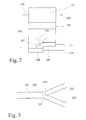
- the separating means 22 can as a divided collecting shaft with subsequent pneumatic conveying be configured, such a configuration is shown in Figure 2.
- the release agent However, 22 can also be used as a fork in a pneumatic delivery line be configured, in this case the delivery line 21 is also a pneumatic Delivery line, which is preceded by an ejector 25.
- the delivery line 21 is also a pneumatic Delivery line, which is preceded by an ejector 25.
- 24 are arranged discharge openings 26, 27.
- the discharge openings, represented by 26a, 27a, into the feed means 2 or the discharge openings, represented by 26b, 27b, are arranged upstream of the feed means 2 in the conveying direction of the strand conveyors 7, 8.
- the opening of the discharge openings 26a, 27a can preferably be arranged in close proximity to the strand conveyors 7, 8, or on one another location between the distribution device 1 and the strand conveyors 7, 8, if this is particularly easy to access in the construction of the machine in question is.
- Each of the discharge openings 26, 27 is on the opposite one Side of the strand conveyor 7, 8 assigned a second vacuum chamber 28, 29 which depending on the position of the discharge openings 26, 27 either, represented by 28a, 29a, are arranged within the first vacuum chamber 15, or are shown through 28b, 29b, the first vacuum chamber 15 in the conveying direction of the strand conveyors 7, 8 are arranged.
- second suction means 35 To the second vacuum chambers 28, 29 are over second exhaust air lines 30, 31, 32 and adjusting means 33, 34 second suction means 35 connected.
- adjusting means 33, 34 for. B. Throttle valves can be used.
- pressure sensors 36, 37, 38 Within the second vacuum chamber 28, 29 and within the first vacuum chamber 15, pressure sensors 36, 37, 38 are arranged, which with a Control unit 39 are connected, which in turn by control lines 40, 41, 42 is connected to the adjusting means 33, 34 and the second suction means 35.
- Tobacco to be processed becomes a wide one in the distribution device 1
- Spread tobacco shower 3 which is delivered into the feed means 2.
- the shower 3 is divided into two showers 5, 6.
- the equalizers 16, 17 excess portions 45, 46 of the Tobacco strands 43, 44 separated.
- air laden with dust 47 passes through the tobacco rods 43, 44 and the strand conveyors 7, 8 in the first vacuum chamber 15.
- This air is by means of the first suction means 20 through the first exhaust line 18 into the dust collector 19 promoted where the dust contained in it separated and into the Conveying line 21 is transferred.
- the dust is then in accordance the description of Figures 2 or 3 divided into two sub-streams, which be introduced into the pneumatic conveying lines 23, 24.
- dust 48, 49 passes through the corresponding discharge openings 26, 27 in the direction of the corresponding strand conveyors 7, 8. flow the discharge openings, represented by 26a, 27a in the feed means 2, the Dust together with the partial showers 5, 6 from tobacco on the strand conveyors 7, 8 heaped up.
- a coarse fraction 50, 51 is already created by the respective one partially retained tobacco rod 43, 44 and with this conveyed together.
- a fine fraction 52, 53 occurs due to the in the second negative pressure chambers 28a, 29a prevailing negative pressure by the corresponding tobacco rod 43, 44 and the corresponding strand conveyor 7, 8 through into the respective second vacuum chamber 28a, 29a. From there the fine Dust fraction 52, 53 by means of the second suction means 35 through the second exhaust air lines 30, 31, 32 suctioned off.
- the coarse dust fraction 50, 51 is retained by the unused strand conveyors 7, 8 while the fine fraction 52, 53 passes through it into the second Vacuum chambers 28b, 29b occurs.
- the negative pressure in the second negative pressure chambers 28, 29 and in the first vacuum chamber 15 is by pressure sensors 36, 37, 38 measured.
- the control unit 39 the throttle valves 33, 34 and / or the drive of the second suction means 35 controlled so that at the transitions between the first vacuum chamber 15 and the second vacuum chambers 28, 29 no pressure jumps occur.
- the mode of operation of the release agents shown in FIG. 2 is as follows: In one Dust contained in air flow supplied through line 102 is removed by a Dust separator 101 separated from the air and through a lock 104, which z. B. can be designed as a rotary valve, in a collecting container 105 transferred. The cleaned air is discharged through a line 103. The Dust falling from the lock 104 into the collecting container 105 is removed by a pivotable partition 106 divided into two sub-streams, each of which by means of one of two ejectors 108, 109 into one of two pneumatic ones assigned to them Delivery lines 110, 111 is abandoned. By swiveling the partition 106 by means of a lever 107, the quantitative ratio of the partial flows of the Dust can be adjusted. Instead of the manually operated lever 107 can also an automatic, e.g. B. electromotive setting.
- the mode of operation of the means shown in FIG. 3 is as follows: one in a feeding Pneumatic feed line 201 supplied dust stream is in one Branch area 203 through the pivotable end 205 of a partition 204 divided into two partial streams, which are discharged through the pneumatic conveying lines 202, 203 are transported away.
- the end 205 of the partition 204 can be the quantitative ratio of the partial flows can be set. As with the means shown in FIG. 2, this setting can be used manually using a lever, not shown, or automatically, e.g. B. electromotive, respectively.
Abstract
Description
Die Erfindung betrifft ein Verfahren zum Bilden mindestens eines Tabakstranges, in welchem Tabakfasern in einem breiten Schauer mindestens einem luftdurchlässigen Strangförderer zugeführt werden und an diesem Förderer mittels Saugluft gehalten werden, ferner in dieser durch den Strangförderer gesaugten Luft enthaltener Staub weitestgehend vollständig aus der Luft abgeschieden wird und dieser abgeschiedene Staub teilweise wieder dem Tabakstrang zugesetzt wird.The invention relates to a method for forming at least one strand of tobacco, in which tobacco fibers in a wide shower at least one air permeable Strand conveyors are fed and on this conveyor by means of suction air are held, further contained in this air sucked by the strand conveyor Dust is largely completely separated from the air and this separated dust is partially added to the tobacco rod.
Die Erfindung betrifft weiterhin eine Vorrichtung zum Bilden mindestens eines Tabakstranges mit einer Verteilereinrichtung zum Bilden eines breiten Schauers aus Tabakfasern, mindestens einem luftdurchlässigen, endlos umlaufenden Strangförderer zum Abfördern des mindestens einen aus dem Schauer gebildeten Tabakstranges, Zuführmitteln zum Zuführen des Schauers zu dem mindestens einen Strangförderer, einer ersten Unterdruckkammer zum Anlegen eines Unterdruckes an einen ersten Abschnitt der dem Tabakstrang abgewandten Seite des mindestens einen Strangförderers, ersten Saugmitteln zum Absaugen der durch den mindestens einen Strangförderer in die erste Unterdruckkammer tretenden Luft, einer Trenneinrichtung zum Abscheiden des in dieser abgesaugten Luft enthaltenen Staubes und Transportmitteln mit mindestens einer Abgabeöffnung zum Transport des abgeschiedenen Staubes zu dem mindestens einen Strangförderer.The invention further relates to a device for forming at least one tobacco rod with a distribution device for forming a wide shower Tobacco fibers, at least one air-permeable, endless circulating strand conveyor for removing the at least one tobacco rod formed from the shower, Feeding means for feeding the shower to the at least one Strand conveyor, a first vacuum chamber for applying a vacuum to a first section of the side of the at least facing away from the tobacco rod a strand conveyor, first suction means for suctioning through the air entering at least one strand conveyor into the first vacuum chamber, a separator for separating the air contained in this extracted Dust and means of transport with at least one discharge opening for transport of the separated dust to the at least one strand conveyor.
Unter dem Begriff tabakverarbeitende Maschinen sind Maschinen zur Herstellung von Zigaretten zu verstehen, ebenso aber auch Maschinen zur Herstellung von Tabakpatronen, Zigarillos oder Zigarren, soweit diese das genannte Verfahren der Strangbildung verwenden.The term tobacco processing machines includes machines for manufacturing understanding of cigarettes, but also machines for producing tobacco cartridges, Cigarillos or cigars, insofar as they follow the procedure mentioned Use strand formation.
Bei den genannten Maschinen wird Tabak durch eine Verteilereinrichtung aus einem
Vorrat entnommen und zu einem Schauer aus weitestgehend vereinzelten Tabakfasern
ausgebreitet. Dieser Tabakschauer wird zumeist durch Transportluft beschleunigt
und abgelenkt und schließlich auf oder unter einem umlaufenden luftdurchlässigen
Strangförderer zu einem endlosen Tabakstrang aufgeschüttet. Dieser
Strang wird an dem Strangförderer durch Unterdruck gehalten, welcher mittels einer
ersten Unterdruckkammer an die dem Strang abgewandten Seite des Strangförderers
angelegt wird. Die durch den Tabakstrang und den Strangförderer tretende Luft
wird durch Saugmittel aus der ersten Unterdruckkammer abgesaugt. Um die Dichte
des Tabakstranges möglichst konstant zu halten, wird der Tabak mit einem Überschuss
zugeführt, welcher später durch einen Egalisator abgetrimmt wird. In modernen
Hochleistungsmaschinen wird oftmals der Tabakschauer in mehrere Teilschauer
aufgeteilt, um mehrere Tabakstränge gleichzeitig auf entsprechenden
Strangförderern aufschütten zu können. Eine entsprechende Verteilereinrichtung ist
z. B. in der DE 39 19 720 A1 der Anmelderin beschrieben. In the machines mentioned, tobacco is made from a distribution device
Taken stock and a shower of largely isolated tobacco fibers
spread. This tobacco shower is usually accelerated by transport air
and distracted and finally on or under a revolving air permeable
Strand conveyor heaped into an endless tobacco rod. This
Strand is held on the strand conveyor by negative pressure, which by means of a
first vacuum chamber on the side of the strand conveyor facing away from the strand
is created. The air passing through the tobacco rod and the line conveyor
is extracted by suction from the first vacuum chamber. About density
To keep the tobacco rod as constant as possible, the tobacco is left with a surplus
which is later trimmed by a leveler. In modern
High-performance machines often turn the tobacco shower into several partial showers
split to match multiple strands of tobacco at the same time
To be able to fill up strand conveyors. A corresponding distribution device is
z. B. described in
Erfahrungsgemäß ist die in den betreffenden Maschinen aus der ersten Unterdruckkammer abgesaugte Luft stark mit Staub belastet. Der genannte Staub besteht aus Feinstaub, welcher den Tabakfasern anhaftet und während der Verarbeitung in der Verteilereinrichtung von diesen abgelöst wird, aus Fremdanteilen wie z. B. Sand und aus kurzen Tabakfasern. Diese kurzen Fasern entstehen zum einen während der Aufbereitung des Tabaks und können in geringer Anzahl durch Öffnungen im Strangförderer in die Unterdruckkammer gelangen. Zum anderen können aber auch die Enden von längeren Fasern teilweise durch diese Öffnungen rutschen, was dazu führt, dass die Fasern beim Ablösen des Stranges vom Strangförderer zerrissen werden und die Enden ebenfalls als kurze Faserbruchstücke in die Unterdruckkammer gelangen.Experience has shown that it is in the machines in question from the first vacuum chamber extracted air is heavily contaminated with dust. The dust mentioned is there made of fine dust, which adheres to the tobacco fibers and during processing in the distribution device is replaced by these, from foreign shares such. B. sand and short tobacco fibers. On the one hand, these short fibers arise during the preparation of the tobacco and can in small numbers through openings get into the vacuum chamber in the strand conveyor. On the other hand, you can but also the ends of longer fibers partially through these openings slip, which causes the fibers to separate from the strand when the strand is detached Strand conveyors are torn and the ends also as short fiber fragments get into the vacuum chamber.
In der Regel wird der gesamte Staub mit der abgesaugten Luft abtransportiert und in einer Zentralentstaubung abgeschieden. In einer solchen Entstaubungsanlage wird gewöhnlich staubbelastete Luft aus einer ganzen Fabrik zusammengeführt und gereinigt. Danach wird der Staub in aufwendigen Verfahren in tabakähnliche Produkte wie z. B. Tabakfolie umgeformt und erneut dem Produktionsprozess zugeführt.As a rule, all of the dust is removed with the extracted air and deposited in a central dedusting system. In such a dedusting plant usually dust-laden air is brought together from an entire factory and cleaned. After that, the dust is transformed into tobacco-like products in elaborate processes such as B. formed tobacco foil and fed again to the production process.
Aus der US 3 282 270 ist ein Verfahren bekannt, diesen Staub direkt an der Maschine aus der Abluft abzuscheiden und diesen dann pneumatisch in den Tabakschauer zurückzuführen. Der Staub soll durch den bereits teilweise aufgeschauerten Tabakstrang aus der Transportluft herausgefiltert werden und im Tabakstrang verbleiben. Dabei ergibt sich der Nachteil, dass nur grobe Staubanteile aus der Luft herausgefiltert werden, während der Feinstaubanteil erneut in die Abluft gelangt und sich so in dem System ansammelt, da mit dem zugeführten Tabak ständig weitere Feinstaubanteile hinzukommen. A method is known from US Pat. No. 3,282,270, this dust directly on the machine separate from the exhaust air and then pneumatically into the tobacco shower due. The dust is said to be due to the already partially shivered The tobacco rod is filtered out of the transport air and in the tobacco rod remain. The disadvantage here is that only coarse dust particles from the air be filtered out, while the fine dust fraction is released into the exhaust air again and so accumulates in the system because with the tobacco fed constantly more fine dust is added.
Daher stellt sich die Aufgabe, ein Verfahren zu entwickeln, bei welchem die groben Staubanteile dem Tabakstrang zugesetzt werden und gleichzeitig die Gefahr einer Ansammlung des Feinstaubes nicht besteht. Zusätzlich besteht die Aufgabe darin, eine Vorrichtung zu entwickeln, welche die Durchführung dieses Verfahrens ermöglicht.Therefore, the task arises to develop a method in which the rough Dust particles are added to the tobacco rod and at the same time there is a risk of There is no accumulation of fine dust. In addition, the task is to develop a device which enables this method to be carried out.
Bei einem Verfahren der eingangs beschriebenen Art wird die Aufgabe erfindungsgemäß dadurch gelöst, dass der weitestgehend gesamte Staub in eine grobe und eine feine Fraktion aufgeteilt wird, wobei die grobe Fraktion dem Tabakstrang zugesetzt wird, während die feine Fraktion einer Zentralentstaubung zugeführt wird.In a method of the type described in the introduction, the object is achieved according to the invention solved that the largely all dust in a coarse and a fine fraction is divided, the coarse fraction being added to the tobacco rod while the fine fraction is fed to a central dedusting unit.
Hierbei sind ausdrücklich auch solche Verfahren inbegriffen, bei denen ein gewisser Anteil des abgeschiedenen Staubes vor der Fraktionierung zeitweise oder kontinuierlich für Mess- oder andere Zwecke entnommen wird. Ebenso sollen solche Verfahren inbegriffen sein, in welchen zusätzlich zu der genannten Abluft auch Abluft aus anderen Teilprozessen der Tabakverarbeitung in der Staubabscheidung gereinigt wird, soweit diese weitere Abluft ebenfalls wiederverwertbare grobe Tabakanteile enthält.This also expressly includes procedures in which a certain Part of the separated dust temporarily or continuously before fractionation for measuring or other purposes. Such procedures are also intended included in which, in addition to the exhaust air mentioned, exhaust air cleaned from other sub-processes of tobacco processing in dust separation as far as this additional exhaust air is also recyclable coarse tobacco parts contains.
Besonders einfach kann ein solches Verfahren dadurch gestaltet werden, dass der Staub gemeinsam mit dem Tabakschauer erneut dem Strangförderer zugeführt wird und die Aufteilung des Staubes in die grobe und die feine Fraktion durch Siebwirkung des Strangförderers und ggf. bereits auf diesem aufgeschütteten Tabak geschieht. Der Rücktransport des abgeschiedenen Staubes zum Strangförderer erfolgt dabei vorzugsweise pneumatisch. Such a method can be designed particularly simply in that the Dust is fed back to the strand conveyor together with the tobacco shower and the division of the dust into the coarse and fine fractions by sieving of the strand conveyor and possibly already on this tobacco heaped up. The separated dust is transported back to the strand conveyor preferably pneumatic.
Für ein Verfahren zur gleichzeitigen Herstellung mehrerer Tabakstränge ist es von Vorteil, wenn der gesamte abgeschiedene Staub in mehrere Teilströme aufgeteilt wird. Vorzugsweise wird jedem herzustellenden Tabakstrang ein Teilstrom des Staubes zugeführt. Die Aufteilung erfolgt vorzugsweise vor oder während des Transportes zu den Strangförderern.For a process for the simultaneous production of several tobacco strands, it is from Advantage if the entire separated dust is divided into several partial flows becomes. Each tobacco rod to be produced is preferably a partial stream of Dust supplied. The division is preferably made before or during the Transportes to the strand conveyors.
Die Siebwirkung kann besonders vorteilhaft ausgenutzt werden, wenn die Zugabe des Staubes auf einer Breite erfolgt, welcher kleiner ist als die Breite des Tabakschauers, wobei die im Bereich der Staubzugabe durch den Strangförderer tretende Luft zusammen mit dem in ihr enthaltenen Feinstaub separat abgesaugt und einer Zentralentstaubung zugeführt wird. Unter der Breite des Tabakschauers ist dessen Ausdehnung in Förderrichtung des Strangförderers zu verstehen.The sieving action can be used particularly advantageously when the addition the dust takes place on a width which is smaller than the width of the tobacco shower, the one passing through the strand conveyor in the area of dust addition Air and the fine dust contained in it are extracted separately and one Central dedusting is supplied. Below is the width of the tobacco shower To understand expansion in the conveying direction of the strand conveyor.
Um möglichst nur sehr große Staubpartikel dem Tabakstrang zuzugeben ist es vorteilhaft, den Staub zuzugeben, bevor die Zuführung des Tabakschauers erfolgt. Um hingegen möglichst nur sehr feine Staubpartikel in die Zentralentstaubung abzuführen ist es vorteilhaft, den Staub mit einem Teil des Tabakschauers gemeinsam dem Strangförderer zuzugeben, da dann die Siebwirkung des Strangförderers durch die Siebwirkung des bereits teilweise aufgeschütteten Tabakstranges verstärkt wird. In diesem Fall ist es weiter von Vorteil, den Staub so zu dem Tabakschauer zuzugeben, dass die grobe Staubfraktion im Tabakstrang außerhalb des Strangbereiches abgeschieden wird, welcher zur Sicherung einer gleichmäßigen Strangdichte im weiteren Prozessverlauf abgetrimmt wird. Da bei Maschinen üblicher Bauart etwa ein Drittel des aufgeschütteten Tabakstranges als Überschuss abgetrimmt wird, muss dazu die Rückgabe des Staubes innerhalb der ersten zwei Drittel der Schauerbreite, gesehen in Förderrichtung des Strangförderers, erfolgen. In order to add only very large dust particles to the tobacco rod, it is advantageous to add the dust before the tobacco shower is fed. In order, on the other hand, to remove only very fine dust particles into the central dedusting system it is beneficial to share the dust with part of the tobacco shower to add the strand conveyor, since then the sieve action of the strand conveyor reinforced by the sieving action of the tobacco rod, which has already been partially heaped up becomes. In this case, it is also advantageous to bring the dust to the tobacco shower admit that the coarse dust fraction in the tobacco rod outside the Strand area is deposited, which to ensure a uniform Strand density is trimmed in the further course of the process. Because more common with machines Design about a third of the heaped tobacco rod as excess the dust must be returned within the first two Third of the shower width, seen in the direction of conveyance of the strand conveyor, take place.
Wird der Staub mit dem Tabakschauer vor dessen Aufschüttung auf den Strangförderer zusammengeführt, ist es besonders einfach, diese Zusammenführung direkt vor der Aufschüttung durchzuführen. Aus konstruktiven Gesichtspunkten kann es aber auch von Vorteil sein, die Zusammenführung schon bei der Ausbreitung des Schauers durchzuführen, ebenso in jeder Phase zwischen den genannten Schritten, in welcher der Tabakschauer in der jeweiligen Maschine gut zugänglich ist.The dust with the tobacco shower before it is heaped up on the strand conveyor merged, it is particularly easy to merge this directly to be carried out before the embankment. From a constructive point of view, it can But it can also be an advantage to merge as soon as the Perform Schauers, also in every phase between the steps mentioned, in which the tobacco shower is easily accessible in the respective machine.
Wird der Staub dem Strangförderer vor der Zuführung des Tabakschauers oder dem Tabakschauer direkt vor dessen Aufschüttung auf den Strangförderer zugegeben, so ist es von Vorteil, dem Staub eine Bewegungskomponente in Förderrichtung des Strangförderers zu geben.If the dust is conveyed to the strand conveyor before the tobacco shower or added to the tobacco shower immediately before it was filled onto the strand conveyor, So it is advantageous to give the dust a component of movement in the conveying direction to give the strand conveyor.
Eine besonders sichere Funktion des Verfahrens wird dadurch erreicht, dass die Menge der separat abgesaugten Luft gesteuert wird. Die Steuerung erfolgt vorzugsweise durch einen Regelkreis, welcher vorteilhafterweise dafür sorgt, dass der Unterdruck entlang des Strangförderers stetig verläuft.A particularly reliable function of the method is achieved in that the The amount of separately extracted air is controlled. The control is preferably carried out through a control loop, which advantageously ensures that the Vacuum runs steadily along the strand conveyor.
Bei einer Vorrichtung der eingangs beschriebenen Art wird die Aufgabe erfindungsgemäß dadurch gelöst, dass im Bereich der Zugabe des abgeschiedenen Staubes zu dem mindestens einen Strangförderer diesem mindestens eine zweite Unterdruckkammer zum Anlegen eines Unterdruckes an einen zweiten Abschnitt der dem Tabakstrang abgewandten Seite des mindestens einen Strangförderers zugeordnet ist, an welchen zweite Saugmittel angeschlossen sind, um die durch den mindestens einen Strangförderer in die mindestens eine zweite Unterdruckkammer tretende Luft abzusaugen. In a device of the type described in the introduction, the object is achieved according to the invention solved that in the area of the addition of the separated dust to the at least one strand conveyor, this at least one second vacuum chamber for applying a vacuum to a second section of the Associated side of the at least one strand conveyor facing away from the tobacco rod is to which second suction means are connected in order to achieve the minimum through the a strand conveyor entering the at least one second vacuum chamber To suck out air.
In einer bevorzugten Ausgestaltung der Vorrichtung beinhalten die Zuführmittel für den Tabakschauer spezielle Mittel zum Aufteilen des Schauers in mehrere Teilschauer, aus welchen auf mehreren Strangförderern jeweils ein Tabakstrang aufgeschüttet wird, und die Transportmittel für den abgeschiedenen Staub beinhalten ebenfalls Mittel zum Aufteilen des Staubes in mehrere Teilströme, welche durch mehrere Abgabeöffnungen den einzelnen Strangförderern zugeführt werden. Ferner ist jedem einzelnen Strangförderer im Bereich der entsprechenden Abgabeöffnung der Transportmittel jeweils eine zweite Unterdruckkammer zugeordnet. In diesem Fall ist es weiter vorteilhaft, wenn die Vorrichtung zum Aufteilen des Staubes Stellmittel enthält, durch welche die Mengenverhältnisse der einzelnen Teilströme des Staubes gesteuert werden können.In a preferred embodiment of the device, the feed means for the tobacco shower special means for dividing the shower into several partial showers, from which a tobacco rod is piled up on several strand conveyors and include the means of transport for the separated dust also means for dividing the dust into several partial streams, which through several discharge openings can be fed to the individual strand conveyors. Further is every single strand conveyor in the area of the corresponding discharge opening a second vacuum chamber is assigned to the means of transport. In this Case, it is further advantageous if the device for dividing the dust Contains adjusting means by which the quantitative relationships of the individual partial flows of the dust can be controlled.
Die Transportmittel für den abgeschiedenen Staub sind vorzugsweise als pneumatische Förderleitungen ausgeführt.The means of transport for the separated dust are preferably pneumatic Delivery lines executed.
In einer vorteilhaften Ausgestaltung der Vorrichtung ist die Ausdehnung der zweiten Unterdruckkammer in Förderrichtung des Strangförderers wesentlich kleiner als die der ersten Unterdruckkammer.In an advantageous embodiment of the device, the extension is the second Vacuum chamber in the conveying direction of the strand conveyor much smaller than that the first vacuum chamber.
In weiteren vorteilhaften Ausgestaltungen der Vorrichtung ist die zweite Unterdruckkammer in Förderrichtung des Strangförderers der ersten Unterdruckkammer vorgeordnet oder in diese integriert.In a further advantageous embodiment of the device, the second vacuum chamber upstream of the first vacuum chamber in the conveying direction of the strand conveyor or integrated into this.
Um einen optimalen Abtransport des Feinstaubes zu gewährleisten, ist in einer weiteren Ausgestaltung der Vorrichtung die zweite Unterdruckkammer in Förderrichtung des Strangförderers größer als die Abgabeöffnung der Transportmittel. Eine weitere Optimierung wird dadurch erreicht, dass die zweite Unterdruckkammer gegen die Abgabeöffnung der Transportmittel in Förderrichtung des Strangförderers versetzt ist.In order to ensure optimal removal of the fine dust, is in one Another embodiment of the device, the second vacuum chamber in the conveying direction of the strand conveyor larger than the delivery opening of the means of transport. A Further optimization is achieved in that the second vacuum chamber against the discharge opening of the transport means in the conveying direction of the strand conveyor is offset.
Die Vorrichtung wird konstruktiv besonders einfach, wenn in einer weiteren Ausgestaltung die Transportmittel mit ihrer Abgabeöffnung in die Zuführmittel für den Tabakschauer einmünden.The device becomes structurally particularly simple if in a further embodiment the transport means with their discharge opening in the feed means for the Open tobacco shower.
Besonders sicher läuft die Vorrichtung, wenn die in direkter Nähe zum Strangförderer angeordnete Abgabeöffnung der Transportmittel mit einer Komponente in Förderrichtung des mindestens einen Strangförderers ausgerichtet ist.The device runs particularly safely when it is in close proximity to the strand conveyor arranged discharge opening of the transport means with a component in the conveying direction of the at least one strand conveyor is aligned.
Vorzugsweise befinden sich in der zweiten Unterdruckkammer und/oder in der ersten Unterdruckkammer Drucksensoren. Weiter sind vorzugsweise Stellmittel für die Steuerung der durch die zweiten Saugmittel abgesaugten Luftmenge vorgesehen. Weiterhin ist vorzugsweise eine Steuereinheit zur Steuerung dieser Luftmenge vorgesehen. They are preferably located in the second vacuum chamber and / or in the first Vacuum chamber pressure sensors. Next are preferably adjusting means for the Control of the amount of air drawn off by the second suction means is provided. Furthermore, a control unit for controlling this amount of air is preferably provided.
Die Erfindung wird nachstehend anhand der in den Zeichnungen dargestellten bevorzugten Ausführungsformen näher erläutert:
Figur 1- zeigt eine schematische Darstellung einer bevorzugten Ausgestaltung einer erfindungsgemäßen Vorrichtung, in welcher gleichzeitig zwei Tabakstränge gebildet werden. Eine erfindungsgemäße Vorrichtung zum Bilden nur eines Tabakstranges ist aus der Darstellung ohne weitere Überlegung abzuleiten.
Figuren 2 und 3- zeigen Trennmittel zur Aufteilung eines Staubstromes in zwei Teil
ströme vor bzw. nach der Aufgabe in eine pneumatische Förderleitung
für den Einsatz in einer Vorrichtung gemäß
Figur 1.
- Figure 1
- shows a schematic representation of a preferred embodiment of a device according to the invention, in which two tobacco rods are formed simultaneously. A device according to the invention for forming only one tobacco rod can be derived from the illustration without further consideration.
- Figures 2 and 3
- show separating means for dividing a dust flow into two partial flows before or after the task in a pneumatic conveying line for use in a device according to FIG. 1.
Die in Figur 1 dargestellte Vorrichtung besteht aus einer Verteilereinrichtung 1, welcher
Zuführmittel 2 zum Führen eines Tabakschauers 3 nachgeordnet sind. Eine
solche Verteilereinrichtung ist z. B. in der DE 39 19 720 A1 der Anmelderin beschrieben
und Bestandteil z. B. der von der Anmelderin vertriebenen Zigarettenproduktionsmaschine
PROTOS 2. In den Zuführmitteln 2 sind Trennmittel 4 zum Aufteilen
des Tabakschauers 3 in zwei Teilschauer 5, 6 angeordnet. Die Zuführmittel 2
führen zu zwei endlosen Strangförderern 7, 8, welche um Umlenkrollen 9, 10, 11,
12 geführt sind und in Richtung von Pfeilen 13, 14 umlaufen. Die Strangförderer 7,
8 begrenzen eine den Zuführmitteln 2 gegenüber positionierte erste Unterdruckkammer
15. Am in Förderrichtung der Strangförderer 7, 8 stromabwärtigen Ende
der ersten Unterdruckkammer 15 ist jedem der Strangförderer 7, 8 ein Egalisator
16, 17 zugeordnet. An die erste Unterdruckkammer 15 sind über eine erste Abluftleitung
18 und einen Staubabscheider 19 erste Saugmittel 20 angeschlossen. Als
Staubabscheider 19 kann z. B. ein Mahle Industriefilter vom Typ SFK 1560 der
Knecht Filterwerke GmbH, Öhringen, Verwendung finden. Vom Staubabscheider 19
führt eine Förderleitung 21 zu Trennmitteln 22 zur Aufteilung eines Staubstromes
auf zwei weiterführende pneumatische Förderleitungen 23, 24. Die Trennmittel 22
können als geteilter Auffangschacht mit anschließender pneumatischer Förderung
ausgestaltet sein, eine solche Ausgestaltung ist in Figur 2 dargestellt. Die Trennmittel
22 können jedoch auch als Gabelung einer pneumatischen Förderleitung
ausgestaltet sein, in diesem Fall ist die Förderleitung 21 ebenfalls eine pneumatische
Förderleitung, welcher ein Ejektor 25 vorgeordnet ist. Am Ende der pneumatischen
Förderleitungen 23, 24 sind Abgabeöffnungen 26, 27 angeordnet. Je nach
Ausgestaltung der Vorrichtung münden die Abgabeöffnungen, dargestellt durch
26a, 27a, in die Zuführmittel 2, oder die Abgabeöffnungen, dargestellt durch 26b,
27b, sind in Förderrichtung der Strangförderer 7, 8 den Zuführmitteln 2 vorgeordnet.
Im ersteren Fall kann die Einmündung der Abgabeöffnungen 26a, 27a vorzugsweise
in direkter Nähe zu den Strangförderern 7, 8 angeordnet sein, oder an einem
anderen Ort zwischen der Verteilereinrichtung 1 und den Strangförderern 7, 8,
wenn dieser bei der betreffenden Maschine konstruktiv besonders einfach zugänglich
ist. Jeder der Abgabeöffnungen 26, 27 ist auf der dieser gegenüberliegenden
Seite der Strangförderer 7,8 eine zweite Unterdruckammer 28, 29 zugeordnet, welche
je nach Position der Abgabeöffnungen 26, 27 entweder, dargestellt durch 28a,
29a, innerhalb der ersten Unterdruckkammer 15 angeordnet sind, oder, dargestellt
durch 28b, 29b, der ersten Unterdruckkammer 15 in Förderrichtung der Strangförderer
7, 8 vorgeordnet sind. An die zweiten Unterdruckkammern 28, 29 sind über
zweite Abluftleitungen 30, 31, 32 und Stellmittel 33, 34 zweite Saugmittel 35 angeschlossen.
Als Stellmittel 33, 34 können z. B. Drosselklappen verwendet werden.
Innerhalb der zweiten Unterdruckkammern 28, 29 und innerhalb der ersten Unterdruckkammer
15 sind Drucksensoren 36, 37, 38 angeordnet, welche mit einer
Steuereinheit 39 verbunden sind, welche wiederum durch Steuerleitungen 40, 41,
42 mit den Stellmitteln 33, 34 und den zweiten Saugmitteln 35 verbunden ist.The device shown in Figure 1 consists of a
Die Wirkungsweise der in Figur 1 dargestellten Vorrichtung wird im folgenden erläutert.
Zu verarbeitender Tabak wird in der Verteilereinrichtung 1 zu einem breiten
Tabakschauer 3 ausgebreitet, welcher in die Zuführmittel 2 abgegeben wird. Durch
die Trennmittel 4 wird der Schauer 3 in zwei Teilschauer 5, 6 aufgeteilt. Diese werden
den Strangförderern 7, 8 zugeführt und an diesen durch den mittels der ersten
Unterdruckkammer 15 angelegten Unterdruck zu Tabaksträngen 43, 44 aufgeschüttet,
welche in Förderrichtung der Strangförderer 7, 8 abgefördert werden.
Hierbei werden durch die Egalisatoren 16, 17 Überschussanteile 45, 46 von den
Tabaksträngen 43, 44 abgetrennt. Durch den in der ersten Unterdruckkammer 15
herrschenden Unterdruck tritt mit Staub 47 beladene Luft durch die Tabakstränge
43, 44 und die Strangförderer 7, 8 in die erste Unterdruckkammer 15. Diese Luft
wird mittels der ersten Saugmittel 20 durch die erste Abluftleitung 18 in den Staubabscheider
19 gefördert, wo der in ihr enthaltene Staub abgeschieden und in die
Förderleitung 21 überführt wird. Durch die Trennmittel 22 wird der Staub dann gemäß
der Beschreibung zu den Figuren 2 oder 3 in zwei Teilströme aufgeteilt, welche
in die pneumatischen Förderleitungen 23, 24 eingebracht werden. Aus den
Förderleitungen 23, 24 tritt der Staub 48, 49 durch die entsprechenden Abgabeöffnungen
26, 27 in Richtung der entsprechenden Strangförderer 7, 8 aus. Münden
die Abgabeöffnungen, dargestellt durch 26a, 27a in die Zuführmittel 2, so wird der
Staub gemeinsam mit den Teilschauern 5, 6 aus Tabak auf den Strangförderern 7,
8 aufgeschüttet. Hierbei wird eine grobe Fraktion 50, 51 durch den jeweiligen bereits
teilweise aufgeschütteten Tabakstrang 43, 44 zurückgehalten und mit diesem
zusammen abgefördert. Eine feine Fraktion 52, 53 tritt dagegen aufgrund des in
den zweiten Unterdruckkammern 28a, 29a herrschenden Unterdruckes durch den
entsprechenden Tabakstrang 43, 44 und den entsprechenden Strangförderer 7, 8
hindurch in die jeweilige zweite Unterdruckkammer 28a, 29a. Von dort wird die feine
Staubfraktion 52, 53 mittels der zweiten Saugmittel 35 durch die zweiten Abluftleitungen
30, 31, 32 abgesaugt. Befinden sich die Abgabeöffnungen, wie durch 26b,
27b dargestellt, in Förderrichtung der Strangförderer 7, 8 vor den Zuführmitteln 2,
so wird die grobe Staubfraktion 50, 51 durch die unbelegten Strangförderer 7,8 zurückgehalten,
während die feine Fraktion 52, 53 durch diese hindurch in die zweiten
Unterdruckkammern 28b, 29b tritt. Der Unterdruck in den zweiten Unterdruckkammern
28, 29 und in der ersten Unterdruckkammer 15 wird durch Drucksensoren 36,
37, 38 gemessen. In Abhängigkeit von den Messwerten werden durch die Steuereinheit
39 die Drosselklappen 33, 34 und/oder der Antrieb der zweiten Saugmittel
35 so gesteuert, dass an den Übergängen zwischen der ersten Unterdruckkammer
15 und den zweiten Unterdruckkammern 28, 29 keine Drucksprünge auftreten. The operation of the device shown in Figure 1 is explained below.
Tobacco to be processed becomes a wide one in the
Die Wirkungsweise der in Figur 2 dargestellten Trennmittel ist wie folgt: In einem
durch eine Leitung 102 zugeführten Luftstrom enthaltener Staub wird durch einen
Staubabscheider 101 aus der Luft abgeschieden und durch eine Schleuse 104,
welche z. B. als Zellenradschleuse ausgestaltet sein kann, in einen Auffangbehälter
105 überführt. Die gereinigte Luft wird durch eine Leitung 103 abgeführt. Der
aus der Schleuse 104 in den Auffangbehälter 105 fallende Staub wird durch eine
schwenkbare Trennwand 106 in zwei Teilströme aufgeteilt, von denen jeder mittels
eines von zwei Ejektoren 108, 109 in eine von zwei diesen zugeordneten pneumatischen
Förderleitungen 110, 111 aufgegeben wird. Durch verschwenken der Trennwand
106 mittels eines Hebels 107 kann das Mengenverhältnis der Teilströme des
Staubes eingestellt werden. Anstelle des manuell zu betätigenden Hebels 107 kann
auch eine automatische, z. B. elektromotorische, Einstellung erfolgen.The mode of operation of the release agents shown in FIG. 2 is as follows: In one
Dust contained in air flow supplied through
Die Wirkungsweise der in Figur 3 dargestellten Mittel ist wie folgt: Ein in einer zuführenden
pneumatischen Förderleitung 201 zugeführter Staubstrom wird in einem
Verzweigungsbereich 203 durch das schwenkbare Ende 205 einer Trennwand 204
in zwei Teilströme aufgeteilt, welche durch die abführenden pneumatischen Förderleitungen
202, 203 abtransportiert werden. Durch Verschwenken des schwenkbaren
Endes 205 der Trennwand 204 kann das Mengenverhältnis der Teilströme
eingestellt werden. Diese Einstellung kann wie bei den in Figur 2 dargestellten Mitteln
manuell mittels eines nicht dargestellten Hebels oder automatisch, z. B. elektromotorisch,
erfolgen.The mode of operation of the means shown in FIG. 3 is as follows: one in a feeding
Claims (26)
Applications Claiming Priority (2)
| Application Number | Priority Date | Filing Date | Title |
|---|---|---|---|
| DE10051031A DE10051031A1 (en) | 2000-10-14 | 2000-10-14 | Method and device for forming a tobacco rod |
| DE10051031 | 2000-10-14 |
Publications (3)
| Publication Number | Publication Date |
|---|---|
| EP1197155A2 true EP1197155A2 (en) | 2002-04-17 |
| EP1197155A3 EP1197155A3 (en) | 2005-06-15 |
| EP1197155B1 EP1197155B1 (en) | 2006-07-26 |
Family
ID=7659831
Family Applications (1)
| Application Number | Title | Priority Date | Filing Date |
|---|---|---|---|
| EP01122991A Expired - Lifetime EP1197155B1 (en) | 2000-10-14 | 2001-09-26 | Method and apparatus for forming a tobacco rod |
Country Status (8)
| Country | Link |
|---|---|
| US (2) | US6877515B2 (en) |
| EP (1) | EP1197155B1 (en) |
| JP (1) | JP2002125650A (en) |
| CN (1) | CN1192727C (en) |
| AT (1) | ATE333805T1 (en) |
| DE (2) | DE10051031A1 (en) |
| ES (1) | ES2266065T3 (en) |
| PL (1) | PL203996B1 (en) |
Cited By (4)
| Publication number | Priority date | Publication date | Assignee | Title |
|---|---|---|---|---|
| EP2238844A1 (en) * | 2009-04-02 | 2010-10-13 | HAUNI Maschinenbau AG | Vacuum system for a machine in the tobacco processing industry |
| EP2462819A3 (en) * | 2010-12-10 | 2014-12-10 | Riedel Filtertechnik GmbH | Regulation assembly for a cigarette manufacturing machine and method for regulating the transport of the cigarette filler |
| EP3020288A1 (en) * | 2014-11-14 | 2016-05-18 | HAUNI Maschinenbau AG | Method and device for forming a tobacco rod from fed tobacco fibres |
| CN105639720A (en) * | 2016-03-24 | 2016-06-08 | 龙岩烟草工业有限责任公司 | Measuring system and method for material loss of pneumatic cut tobacco feeding system |
Families Citing this family (4)
| Publication number | Priority date | Publication date | Assignee | Title |
|---|---|---|---|---|
| CA2499853C (en) * | 2004-03-15 | 2012-11-13 | Universal Leaf Tobacco Company, Inc. | Apparatus and method for scanning and sorting tobacco leaves |
| DE102005015781A1 (en) * | 2005-04-01 | 2006-10-05 | Hauni Maschinenbau Ag | Method and device for drying a fibrous material |
| US8281931B2 (en) * | 2009-09-18 | 2012-10-09 | Key Technology, Inc. | Apparatus and method for post-threshing inspection and sorting of tobacco lamina |
| ES1078301Y (en) * | 2012-08-06 | 2013-03-20 | Univ Alicante | Device for the incorporation of insoluble solid powder additives into tobacco |
Citations (7)
| Publication number | Priority date | Publication date | Assignee | Title |
|---|---|---|---|---|
| US3282270A (en) * | 1960-02-09 | 1966-11-01 | Molins Organisation Ltd | Tobacco-manipulating apparatus |
| GB1103703A (en) * | 1964-09-15 | 1968-02-21 | Vokes Ltd | Improvements in dust collector systems for cigarette making machines |
| US4003385A (en) * | 1974-02-18 | 1977-01-18 | Hauni-Werke Korber & Co., Kg | Method and machine for making cigarettes or the like |
| DE3919720A1 (en) * | 1989-06-16 | 1990-12-20 | Hauni Werke Koerber & Co Kg | METHOD AND DEVICE FOR THE SIMULTANEOUS PRODUCTION OF TWO CONTINUOUS TOBACCO STRIPS |
| EP0692200A1 (en) * | 1994-07-15 | 1996-01-17 | Fabriques De Tabac Reunies S.A. | Method and apparatus for the dedusting and the cooling of the exhaust air in a machine for making cigarettes |
| EP0738477A1 (en) * | 1995-04-22 | 1996-10-23 | Hauni Maschinenbau Aktiengesellschaft | Method and device for treating the exhaust air in the production of articles in the tobacco industry |
| US5660265A (en) * | 1994-03-09 | 1997-08-26 | Hauni Maschinenbau Ag | Vibratory conveyor for particles of bulk material |
Family Cites Families (2)
| Publication number | Priority date | Publication date | Assignee | Title |
|---|---|---|---|---|
| US4281670A (en) | 1977-06-13 | 1981-08-04 | Hauni-Werke Korber & Co. Kg | Apparatus for increasing the permeability of wrapping material for rod-shaped smokers products |
| DE3544769C2 (en) | 1985-12-18 | 1994-12-08 | Hauni Werke Koerber & Co Kg | Strand machine for producing rod-shaped articles in the tobacco processing industry |
-
2000
- 2000-10-14 DE DE10051031A patent/DE10051031A1/en not_active Withdrawn
-
2001
- 2001-09-25 JP JP2001290984A patent/JP2002125650A/en not_active Withdrawn
- 2001-09-26 ES ES01122991T patent/ES2266065T3/en not_active Expired - Lifetime
- 2001-09-26 EP EP01122991A patent/EP1197155B1/en not_active Expired - Lifetime
- 2001-09-26 DE DE50110533T patent/DE50110533D1/en not_active Expired - Lifetime
- 2001-09-26 AT AT01122991T patent/ATE333805T1/en not_active IP Right Cessation
- 2001-10-11 PL PL350074A patent/PL203996B1/en not_active IP Right Cessation
- 2001-10-12 CN CNB011411902A patent/CN1192727C/en not_active Expired - Fee Related
- 2001-10-15 US US09/976,291 patent/US6877515B2/en not_active Expired - Fee Related
-
2003
- 2003-09-05 US US10/655,213 patent/US6814080B2/en not_active Expired - Fee Related
Patent Citations (7)
| Publication number | Priority date | Publication date | Assignee | Title |
|---|---|---|---|---|
| US3282270A (en) * | 1960-02-09 | 1966-11-01 | Molins Organisation Ltd | Tobacco-manipulating apparatus |
| GB1103703A (en) * | 1964-09-15 | 1968-02-21 | Vokes Ltd | Improvements in dust collector systems for cigarette making machines |
| US4003385A (en) * | 1974-02-18 | 1977-01-18 | Hauni-Werke Korber & Co., Kg | Method and machine for making cigarettes or the like |
| DE3919720A1 (en) * | 1989-06-16 | 1990-12-20 | Hauni Werke Koerber & Co Kg | METHOD AND DEVICE FOR THE SIMULTANEOUS PRODUCTION OF TWO CONTINUOUS TOBACCO STRIPS |
| US5660265A (en) * | 1994-03-09 | 1997-08-26 | Hauni Maschinenbau Ag | Vibratory conveyor for particles of bulk material |
| EP0692200A1 (en) * | 1994-07-15 | 1996-01-17 | Fabriques De Tabac Reunies S.A. | Method and apparatus for the dedusting and the cooling of the exhaust air in a machine for making cigarettes |
| EP0738477A1 (en) * | 1995-04-22 | 1996-10-23 | Hauni Maschinenbau Aktiengesellschaft | Method and device for treating the exhaust air in the production of articles in the tobacco industry |
Cited By (4)
| Publication number | Priority date | Publication date | Assignee | Title |
|---|---|---|---|---|
| EP2238844A1 (en) * | 2009-04-02 | 2010-10-13 | HAUNI Maschinenbau AG | Vacuum system for a machine in the tobacco processing industry |
| EP2462819A3 (en) * | 2010-12-10 | 2014-12-10 | Riedel Filtertechnik GmbH | Regulation assembly for a cigarette manufacturing machine and method for regulating the transport of the cigarette filler |
| EP3020288A1 (en) * | 2014-11-14 | 2016-05-18 | HAUNI Maschinenbau AG | Method and device for forming a tobacco rod from fed tobacco fibres |
| CN105639720A (en) * | 2016-03-24 | 2016-06-08 | 龙岩烟草工业有限责任公司 | Measuring system and method for material loss of pneumatic cut tobacco feeding system |
Also Published As
| Publication number | Publication date |
|---|---|
| EP1197155B1 (en) | 2006-07-26 |
| ES2266065T3 (en) | 2007-03-01 |
| CN1192727C (en) | 2005-03-16 |
| US6877515B2 (en) | 2005-04-12 |
| JP2002125650A (en) | 2002-05-08 |
| EP1197155A3 (en) | 2005-06-15 |
| US6814080B2 (en) | 2004-11-09 |
| PL203996B1 (en) | 2009-11-30 |
| US20040060570A1 (en) | 2004-04-01 |
| PL350074A1 (en) | 2002-04-22 |
| ATE333805T1 (en) | 2006-08-15 |
| DE10051031A1 (en) | 2002-04-18 |
| US20020043268A1 (en) | 2002-04-18 |
| CN1347669A (en) | 2002-05-08 |
| DE50110533D1 (en) | 2006-09-07 |
Similar Documents
| Publication | Publication Date | Title |
|---|---|---|
| EP1364588B1 (en) | Arrangement and method for the formation of at least two tobacco rods in a cigarette rod making machine | |
| EP2363029A1 (en) | Transport drum for the tobacco processing industry | |
| DE1245820B (en) | Apparatus for forming a continuous stream of tobacco | |
| EP2505087B1 (en) | Method and device for manufacturing rods for the tobacco industry | |
| EP2026669B1 (en) | Method of operating a rod-making machine and rod-making machine | |
| EP1197155B1 (en) | Method and apparatus for forming a tobacco rod | |
| DE2359193A1 (en) | CIGARETTE STRANDING MACHINE | |
| DE3345609A1 (en) | METHOD AND DEVICE FOR MAKING ROD-SHAPED ITEMS OF THE TOBACCO-PROCESSING INDUSTRY | |
| DE10035692A1 (en) | Method and device for separating tobacco fibers | |
| DE3744562A1 (en) | Tobacco conveying device for cigarette manufacturing machines | |
| EP1106086B1 (en) | Method for transporting rod-like articles and container transporting apparatus | |
| EP1520488A1 (en) | Device for removing impurities from a tobacco flow | |
| DE19508139A1 (en) | Device for removing excess process air from a distributor of a tobacco processing machine | |
| EP1275311A2 (en) | Device for preparing a stream of fibres in the tobacco industry | |
| EP1250855A1 (en) | Method and device for eliminating a disturbance from a tobacco channel in a rod making machine | |
| DE3919720C2 (en) | Method and device for the simultaneous production of two continuous tobacco rods | |
| EP2253230B1 (en) | Suction rod conveyor and method for manufacturing a strand for the tobacco industry | |
| EP0937415B1 (en) | Apparatus for removing rod-like articles from a seat of a rotary conveyor in the tobacco industry | |
| DE3232792A1 (en) | Conveying apparatus for bar-shaped articles of the tobacco-processing industry | |
| EP1405573B1 (en) | Egalisator for a cigarette rod machine | |
| EP1529449A1 (en) | Apparatus for separating tobacco and air, and arrangement and method for the formation of at least two tobacco rods in a cigarette rod making machine | |
| DE2942604A1 (en) | METHOD AND SYSTEM FOR SEPARATING CUTTED TOBACCO FILLINGS FROM HELLOW MOLDED CIGARETTES | |
| EP2604131A1 (en) | Operation of a filter application machine | |
| DE4336453A1 (en) | Method and device for separating tobacco fibers | |
| DE3508497A1 (en) | METHOD AND DEVICE FOR MAKING TOBACCO PORTIONS, ESPECIALLY FOR THE PRODUCTION OF A TOBACCO STRAND MADE FROM SEPARATE TOBACCO SECTIONS OF DIFFERENT KINDS |
Legal Events
| Date | Code | Title | Description |
|---|---|---|---|
| PUAI | Public reference made under article 153(3) epc to a published international application that has entered the european phase |
Free format text: ORIGINAL CODE: 0009012 |
|
| AK | Designated contracting states |
Kind code of ref document: A2 Designated state(s): AT BE CH CY DE DK ES FI FR GB GR IE IT LI LU MC NL PT SE TR |
|
| AX | Request for extension of the european patent |
Free format text: AL;LT;LV;MK;RO;SI |
|
| PUAL | Search report despatched |
Free format text: ORIGINAL CODE: 0009013 |
|
| AK | Designated contracting states |
Kind code of ref document: A3 Designated state(s): AT BE CH CY DE DK ES FI FR GB GR IE IT LI LU MC NL PT SE TR |
|
| AX | Request for extension of the european patent |
Extension state: AL LT LV MK RO SI |
|
| 17P | Request for examination filed |
Effective date: 20051011 |
|
| AKX | Designation fees paid |
Designated state(s): AT BE CH CY DE DK ES FI FR GB GR IE IT LI LU MC NL PT SE TR |
|
| GRAP | Despatch of communication of intention to grant a patent |
Free format text: ORIGINAL CODE: EPIDOSNIGR1 |
|
| GRAS | Grant fee paid |
Free format text: ORIGINAL CODE: EPIDOSNIGR3 |
|
| GRAA | (expected) grant |
Free format text: ORIGINAL CODE: 0009210 |
|
| AK | Designated contracting states |
Kind code of ref document: B1 Designated state(s): AT BE CH CY DE DK ES FI FR GB GR IE IT LI LU MC NL PT SE TR |
|
| PG25 | Lapsed in a contracting state [announced via postgrant information from national office to epo] |
Ref country code: IE Free format text: LAPSE BECAUSE OF FAILURE TO SUBMIT A TRANSLATION OF THE DESCRIPTION OR TO PAY THE FEE WITHIN THE PRESCRIBED TIME-LIMIT Effective date: 20060726 Ref country code: FI Free format text: LAPSE BECAUSE OF FAILURE TO SUBMIT A TRANSLATION OF THE DESCRIPTION OR TO PAY THE FEE WITHIN THE PRESCRIBED TIME-LIMIT Effective date: 20060726 |
|
| REG | Reference to a national code |
Ref country code: GB Ref legal event code: FG4D Free format text: NOT ENGLISH |
|
| REG | Reference to a national code |
Ref country code: CH Ref legal event code: EP |
|
| GBT | Gb: translation of ep patent filed (gb section 77(6)(a)/1977) |
Effective date: 20060726 |
|
| REG | Reference to a national code |
Ref country code: IE Ref legal event code: FG4D Free format text: LANGUAGE OF EP DOCUMENT: GERMAN |
|
| REF | Corresponds to: |
Ref document number: 50110533 Country of ref document: DE Date of ref document: 20060907 Kind code of ref document: P |
|
| PG25 | Lapsed in a contracting state [announced via postgrant information from national office to epo] |
Ref country code: BE Free format text: LAPSE BECAUSE OF NON-PAYMENT OF DUE FEES Effective date: 20060930 Ref country code: MC Free format text: LAPSE BECAUSE OF NON-PAYMENT OF DUE FEES Effective date: 20060930 |
|
| PG25 | Lapsed in a contracting state [announced via postgrant information from national office to epo] |
Ref country code: DK Free format text: LAPSE BECAUSE OF FAILURE TO SUBMIT A TRANSLATION OF THE DESCRIPTION OR TO PAY THE FEE WITHIN THE PRESCRIBED TIME-LIMIT Effective date: 20061026 Ref country code: SE Free format text: LAPSE BECAUSE OF FAILURE TO SUBMIT A TRANSLATION OF THE DESCRIPTION OR TO PAY THE FEE WITHIN THE PRESCRIBED TIME-LIMIT Effective date: 20061026 |
|
| PG25 | Lapsed in a contracting state [announced via postgrant information from national office to epo] |
Ref country code: PT Free format text: LAPSE BECAUSE OF FAILURE TO SUBMIT A TRANSLATION OF THE DESCRIPTION OR TO PAY THE FEE WITHIN THE PRESCRIBED TIME-LIMIT Effective date: 20061226 |
|
| REG | Reference to a national code |
Ref country code: IE Ref legal event code: FD4D |
|
| ET | Fr: translation filed | ||
| REG | Reference to a national code |
Ref country code: ES Ref legal event code: FG2A Ref document number: 2266065 Country of ref document: ES Kind code of ref document: T3 |
|
| PLBE | No opposition filed within time limit |
Free format text: ORIGINAL CODE: 0009261 |
|
| STAA | Information on the status of an ep patent application or granted ep patent |
Free format text: STATUS: NO OPPOSITION FILED WITHIN TIME LIMIT |
|
| 26N | No opposition filed |
Effective date: 20070427 |
|
| PGFP | Annual fee paid to national office [announced via postgrant information from national office to epo] |
Ref country code: ES Payment date: 20070926 Year of fee payment: 7 |
|
| PG25 | Lapsed in a contracting state [announced via postgrant information from national office to epo] |
Ref country code: AT Free format text: LAPSE BECAUSE OF NON-PAYMENT OF DUE FEES Effective date: 20060926 |
|
| BERE | Be: lapsed |
Owner name: HAUNI MASCHINENBAU A.G. Effective date: 20060930 |
|
| PG25 | Lapsed in a contracting state [announced via postgrant information from national office to epo] |
Ref country code: GR Free format text: LAPSE BECAUSE OF FAILURE TO SUBMIT A TRANSLATION OF THE DESCRIPTION OR TO PAY THE FEE WITHIN THE PRESCRIBED TIME-LIMIT Effective date: 20061027 |
|
| PGFP | Annual fee paid to national office [announced via postgrant information from national office to epo] |
Ref country code: FR Payment date: 20070914 Year of fee payment: 7 |
|
| PG25 | Lapsed in a contracting state [announced via postgrant information from national office to epo] |
Ref country code: LU Free format text: LAPSE BECAUSE OF NON-PAYMENT OF DUE FEES Effective date: 20060926 Ref country code: TR Free format text: LAPSE BECAUSE OF FAILURE TO SUBMIT A TRANSLATION OF THE DESCRIPTION OR TO PAY THE FEE WITHIN THE PRESCRIBED TIME-LIMIT Effective date: 20060726 |
|
| PG25 | Lapsed in a contracting state [announced via postgrant information from national office to epo] |
Ref country code: CY Free format text: LAPSE BECAUSE OF FAILURE TO SUBMIT A TRANSLATION OF THE DESCRIPTION OR TO PAY THE FEE WITHIN THE PRESCRIBED TIME-LIMIT Effective date: 20060726 |
|
| REG | Reference to a national code |
Ref country code: FR Ref legal event code: ST Effective date: 20090529 |
|
| PG25 | Lapsed in a contracting state [announced via postgrant information from national office to epo] |
Ref country code: FR Free format text: LAPSE BECAUSE OF NON-PAYMENT OF DUE FEES Effective date: 20080930 |
|
| REG | Reference to a national code |
Ref country code: ES Ref legal event code: FD2A Effective date: 20080927 |
|
| PG25 | Lapsed in a contracting state [announced via postgrant information from national office to epo] |
Ref country code: ES Free format text: LAPSE BECAUSE OF NON-PAYMENT OF DUE FEES Effective date: 20080927 |
|
| PGFP | Annual fee paid to national office [announced via postgrant information from national office to epo] |
Ref country code: GB Payment date: 20100929 Year of fee payment: 10 |
|
| PGFP | Annual fee paid to national office [announced via postgrant information from national office to epo] |
Ref country code: NL Payment date: 20100929 Year of fee payment: 10 |
|
| PGFP | Annual fee paid to national office [announced via postgrant information from national office to epo] |
Ref country code: CH Payment date: 20101015 Year of fee payment: 10 |
|
| REG | Reference to a national code |
Ref country code: NL Ref legal event code: V1 Effective date: 20120401 |
|
| REG | Reference to a national code |
Ref country code: CH Ref legal event code: PL |
|
| GBPC | Gb: european patent ceased through non-payment of renewal fee |
Effective date: 20110926 |
|
| PG25 | Lapsed in a contracting state [announced via postgrant information from national office to epo] |
Ref country code: NL Free format text: LAPSE BECAUSE OF NON-PAYMENT OF DUE FEES Effective date: 20120401 Ref country code: CH Free format text: LAPSE BECAUSE OF NON-PAYMENT OF DUE FEES Effective date: 20110930 Ref country code: LI Free format text: LAPSE BECAUSE OF NON-PAYMENT OF DUE FEES Effective date: 20110930 |
|
| PG25 | Lapsed in a contracting state [announced via postgrant information from national office to epo] |
Ref country code: GB Free format text: LAPSE BECAUSE OF NON-PAYMENT OF DUE FEES Effective date: 20110926 |
|
| REG | Reference to a national code |
Ref country code: DE Ref legal event code: R081 Ref document number: 50110533 Country of ref document: DE Owner name: HAUNI MASCHINENBAU GMBH, DE Free format text: FORMER OWNER: HAUNI MASCHINENBAU AG, 21033 HAMBURG, DE |
|
| PGFP | Annual fee paid to national office [announced via postgrant information from national office to epo] |
Ref country code: DE Payment date: 20160930 Year of fee payment: 16 |
|
| PGFP | Annual fee paid to national office [announced via postgrant information from national office to epo] |
Ref country code: IT Payment date: 20160930 Year of fee payment: 16 |
|
| REG | Reference to a national code |
Ref country code: DE Ref legal event code: R119 Ref document number: 50110533 Country of ref document: DE |
|
| PG25 | Lapsed in a contracting state [announced via postgrant information from national office to epo] |
Ref country code: DE Free format text: LAPSE BECAUSE OF NON-PAYMENT OF DUE FEES Effective date: 20180404 |
|
| PG25 | Lapsed in a contracting state [announced via postgrant information from national office to epo] |
Ref country code: IT Free format text: LAPSE BECAUSE OF NON-PAYMENT OF DUE FEES Effective date: 20170926 |