EP1197142B1 - Hen nesting apparatus and method utilizing such apparatus for identifying, monitoring and controlling individual hens of a flock - Google Patents
Hen nesting apparatus and method utilizing such apparatus for identifying, monitoring and controlling individual hens of a flock Download PDFInfo
- Publication number
- EP1197142B1 EP1197142B1 EP01129336A EP01129336A EP1197142B1 EP 1197142 B1 EP1197142 B1 EP 1197142B1 EP 01129336 A EP01129336 A EP 01129336A EP 01129336 A EP01129336 A EP 01129336A EP 1197142 B1 EP1197142 B1 EP 1197142B1
- Authority
- EP
- European Patent Office
- Prior art keywords
- hen
- cage
- egg
- ejector
- cages
- Prior art date
- Legal status (The legal status is an assumption and is not a legal conclusion. Google has not performed a legal analysis and makes no representation as to the accuracy of the status listed.)
- Expired - Lifetime
Links
- 244000144992 flock Species 0.000 title claims description 29
- 238000000034 method Methods 0.000 title claims description 15
- 238000012544 monitoring process Methods 0.000 title description 10
- 235000013601 eggs Nutrition 0.000 claims description 76
- 230000000712 assembly Effects 0.000 claims description 8
- 238000000429 assembly Methods 0.000 claims description 8
- 238000010168 coupling process Methods 0.000 claims description 4
- 238000005859 coupling reaction Methods 0.000 claims description 4
- 230000004044 response Effects 0.000 claims description 4
- 230000017448 oviposition Effects 0.000 claims description 3
- 230000008878 coupling Effects 0.000 claims 2
- 230000001276 controlling effect Effects 0.000 description 12
- 238000010276 construction Methods 0.000 description 7
- 230000004048 modification Effects 0.000 description 6
- 238000012986 modification Methods 0.000 description 6
- 230000005484 gravity Effects 0.000 description 4
- 230000000694 effects Effects 0.000 description 2
- 230000003287 optical effect Effects 0.000 description 2
- 238000013459 approach Methods 0.000 description 1
- 230000005540 biological transmission Effects 0.000 description 1
- 230000001143 conditioned effect Effects 0.000 description 1
- 238000010586 diagram Methods 0.000 description 1
- 238000005192 partition Methods 0.000 description 1
- 230000000737 periodic effect Effects 0.000 description 1
- 230000001105 regulatory effect Effects 0.000 description 1
Images


Classifications
-
- A—HUMAN NECESSITIES
- A01—AGRICULTURE; FORESTRY; ANIMAL HUSBANDRY; HUNTING; TRAPPING; FISHING
- A01K—ANIMAL HUSBANDRY; AVICULTURE; APICULTURE; PISCICULTURE; FISHING; REARING OR BREEDING ANIMALS, NOT OTHERWISE PROVIDED FOR; NEW BREEDS OF ANIMALS
- A01K31/00—Housing birds
- A01K31/14—Nest-boxes, e.g. for singing birds or the like
- A01K31/16—Laying nests for poultry; Egg collecting
-
- A—HUMAN NECESSITIES
- A01—AGRICULTURE; FORESTRY; ANIMAL HUSBANDRY; HUNTING; TRAPPING; FISHING
- A01K—ANIMAL HUSBANDRY; AVICULTURE; APICULTURE; PISCICULTURE; FISHING; REARING OR BREEDING ANIMALS, NOT OTHERWISE PROVIDED FOR; NEW BREEDS OF ANIMALS
- A01K1/00—Housing animals; Equipment therefor
- A01K1/0005—Stable partitions
- A01K1/0017—Gates, doors
- A01K1/0029—Crowding gates or barriers
Definitions
- the present invention relates to a hen nesting apparatus, and to a method utilizing such apparatus for identifying, monitoring, and controlling individual hens of a flock, such as for broody (nesting) control.
- the invention is particularly, but not exclusively, useful with respect to turkey hens and is therefore described below in connection with this application.
- Nesting apparatuses are known, for example, as described in Israel Patent No. 52211 (U.S. Patent No. 4,188,911), issued to Rafaely, for turkey hens which include a line of nesting cages and an ejector assembly in each cage actuatable to eject a hen from the cage.
- the ejector assemblies of all the cages are actuated at the same times according to fixed intervals, for example, at 45 minute intervals.
- Such constructions therefore do not maximize the use of the nesting cages.
- the current methods of broody control generally deal with the flocks as a whole, and therefore do not maximize the egg output of the individual hens within a flock.
- An object of the present invention is to provide a hen nesting apparatus having advantages in the above respects.
- Another object of the invention is to provide a hen nesting apparatus, and also a method utilizing such apparatus for identifying, monitoring, and controlling individual hens of a flock, such as for controlling the brooding of a flock of hens in order to maximize their egg output.
- a hen nesting apparatus comprising: a transponder attachable to each hen effective, upon being interrogated by an antenna, to transmit a signal identifying the respective hen; a line of nesting cages; a carriage movable along a path traversing the line of cages; a carriage drive for driving the carriage; an encoder for continuously indicating the instantaneous position of the carriage with respect to the cages traversed by the carriage; and a receiver for receiving the signals from the transponder and for thereby identifying the hens in the cages as traversed by the carriage.
- a method for controlling individual hens of a flock comprising: providing the flock of hens with a line of nesting cages each including an ejector member actuatable to eject a hen therefrom; sensing the occurrence of a specified condition with respect to the individual hens; controlling the ejector assembly of a nesting cage occupied by a hen in response to sensing the occurrence of the specified condition with respect to the respective hen; attaching to each hen a transponder effective, upon being interrogated, to transmit a signal identifying the respective hen; moving an antenna along the line of nesting cases for interrogating the transponders carried by the hens in the cages; receiving identification signals from the transponders as they are interrogated by the antenna; determining the instantaneous position of the antenna at the time a signal is received from an interrogated transponder, to thereby identify the hen in each cage occupied by a hen; and upon determining
- a method for identifying individual hens of a flock comprising: providing the flock of hens with a line of nesting cages; attaching to each hen a transponder effective, upon being interrogated, to transmit a signal identifying the respective hen; moving an antenna along the line of the nesting cages for interrogating the transponders carried by the hens in the cages; receiving identification signals from the transponders as they are interrogated by the antenna; and determining the instantaneous position of the antenna at the time a signal is received from an interrogated transponder to thereby identify the hen in each cage occupied by a hen.
- the apparatus and method of the present invention enable individual hens of a flock to be identified, monitored, and controlled, for producing a maximum egg output from the flock of hens. Further features and advantages of the invention are apparent from the description below.
- the present invention relates to a hen nesting apparatus, and to a method utilizing such apparatus for identifying, monitoring, and controlling individual hens of a flock, such as for broody (nesting) control.
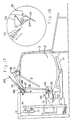
- the nesting apparatus shown in Figs. 1 - 16 illustrates a preferred embodiment of the invention for identifying, monitoring, and controlling individual hens of a flock, particularly a flock of turkey hens, for producing a maximum egg output from the flock of hens.
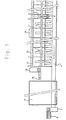
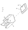
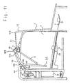
- the apparatus includes a line of nesting cages 2 for the hens to shelter them from disturbances at the time of nesting.
- each cage includes a trap 3 which is normally open and automatically closes when a hen enters the cage, and an ejector member in the form of an ejector frame 50 which is actuated in order to gently eject the hen from the cage so as to permit the cage to be used for other hens.
- All the ejector frames 50 in the line of cages 2 are actuated by a common drive shaft 5 which is rotated in one direction by the forward movement of a pneumatic piston-cylinder drive 6 (Fig. 1), and rotated in the return direction by the return movement of the piston-cylinder drive 6 .
- the eggs are collected from all the cages 2 by a conveyor belt 7 which extends along one side of the line of nesting cages 2.
- the conveyor belt 7 is driven by a motor 8 carried by a base 9 at one end of the apparatus so that the conveyor belt traverses the line of cages 2 in order to receive the eggs and to convey them to a collection table 10.
- the cages 2 are defined by a plurality of partition plates 11 mounted to a frame structure 12.
- the drive shaft 5 is rotatably supported by the frame structure to overlie the upper ends of all the cages 2.
- the ejector member of each cage is individually controlled to enable the ejector member of a particular cage to be individually actuated independently of the ejector members of the other cages when an egg has been laid in the respective cage, and/or when another specified condition with respect to an individual hen has occurred. Accordingly, the apparatus and method of the present invention enable individual hens of a flock to be identified, monitored, and controlled, for producing a maximum egg output from the flock of hens.
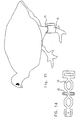
- each hen is provided with a transponder, generally designated 15 (Figs. 14 and 15), attached to a retaining band 16 applied to a leg of the hen.
- Each transponder 15 includes an identification of the respective hen and cooperates with a reader 18 (shown in Figs. 1, 4, 10 - 13, 16, and 17) carrying an antenna 19 (Figs. 10 - 13, and 17) which traverses the line of nesting cages in close proximity to the transponders 15 of the hens within the cages.
- the reader 18 interrogates the transponders 15 in sequence by transmitting a power burst by way of antenna 19.
- the power burst charges each transponder 15 and enables it to transmit a return signal that carries the hen identification and/or other data stored in the transponder 15 for the respective hen.
- transponder/reader system that may be used is that supplied by Texas Instruments under the trademark "TIRIS"; it is based on low-frequency FM transmission techniques.
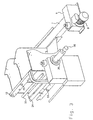
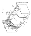
- each cage 2 is inclined downwardly towards the egg conveyor 7 so that any egg laid in the respective cage moves by gravity onto the conveyor 7.
- the egg conveyor 7 is supported by a frame member 21 below the respective end of the cage bottom wall 20.
- an egg sensor in the form of a bail-shaped member 22 is pivotally mounted across the respective end of each cage, adjacent to the egg conveyor 7 so that this member is engaged and pivoted by an egg moving by gravity from the cage bottom wall 20 (Figs. 7, 8, and, 10 - 13) onto the egg conveyor 7.
- the bail 22 actuates an electrical switch 23, which thereby provides a signal to a controller 60 (Fig. 16) that an egg has been laid in the respective cage.
- Each cage is provided with an ejector assembly, which includes the previously mentioned ejector frame 50, actuated when the egg sensor (electrical switch 23 actuated by bail 22 ) has sensed that a hen has laid an egg in the respective cage and/or when another specified condition with respect to an individual hen has occurred.
- the ejector actuator system actuates the ejector assembly of the respective cage to eject the hen then in the cage.
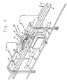
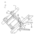
- the common actuator system for all the ejector bars includes a carriage, generally designated 30, supported at its opposite ends by two upper rollers 31 and a lower roller 32 movable along opposite sides of a guide rod 33 adjacent to the upper ends of all the cages 2 (Figs. 1 and 2).
- Carriage 30 is driven by a closed-loop belt 34 rotated by a motor 35 (Figs. 1 and 3) supported at one end of the frame structure 12.
- An encoder 36 (Figs. 1 and 3) provides an electrical indication of the instantaneous position of the carriage 30.
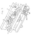
- Carriage 30 is coupled to the closed-loop belt 34 by a two-part slip-coupling, best seen in Figs. 5 and 6.
- One part 37 is secured to the carriage 30, for example, as shown at 37A in Fig. 5, and includes a pair of rollers 37B (shown in Fig. 6; location only shown in Fig. 5) receivable within recesses 38A of the second part 38 fixed to the belt 34.
- rollers 37B are seated in recess 38A to thereby couple the carriage 30 to the belt 34; however, should movement of the carriage 30 be blocked by an obstacle, roller 37B will unseat from recesses 38A, to thereby prevent damage to the belt 34 or to motor 35 driving it.
- carriage 30 carries a solenoid 40 which, in this embodiment, is energized by the actuation of one of the egg sensors (switch 23, Fig. 2) when an egg has been laid in a particular cage or when another specified condition with respect to a particular hen has occurred.
- Solenoid 40 is coupled to one end of a pivotal link 41.
- the opposite end of link 41 is pivotally coupled to a second link 42 also pivotally mounted to the carriage 30.
- the two links 41 and 42 are pivotally mounted at an angle to each other such that they form an apex at their juncture 43 which is at a relatively low position when solenoid 40 is not energized, but which is moved to a higher position when the solenoid is energized.
- the apex 43 between the two links 41 and 42 serves as an actuator for actuating the ejector assembly of a particular cage when a hen has laid an egg therein as sensed by the egg sensor switch 23, and/or when another specified condition has occurred.
- the ejector assembly of each cage includes a roller 44 projecting through an opening 45 in the apparatus frame 12.
- solenoid 40 is not energized, so that the apex 43 between the two links 41 and 42 passes under all the rollers 44; however, when solenoid 40 is energized, apex 43 is moved upwardly to engage the next roller 44 which it encounters during its movement by carriage 30 across the line of cages.
- roller 44 is coupled to one end of a lever 46 formed with a shoulder 47.
- This shoulder normally seats one end 48A of a clutch bar 48 pivotally mounted at point 48C to the ejector frame 50 such that the opposite end 48B of the clutch bar 48 is normally raised above a clutch segment 49 secured to the drive shaft 5.
- lever 46 is pivoted to permit clutch bar 48 to pivot clockwise (Fig. 10), to bring its end 48B into alignment with clutch segment 49 (Fig. 11), and thereby to couple the clutch bar 48 to the drive shaft 5.
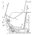
- clutch bar 48 is pivotally mounted at 48C to the ejector frame 50 such that when the clutch bar is coupled to drive shaft 5 it pivots the ejector frame 50.
- the ejector frame 50 pivotally mounts ejector bar 4 and also trap 3.
- the arrangement is such that when the ejector frame 50 is pivoted in a counter-clockwise direction, as shown in Figs. 11 - 13, the ejector frame 50 moves the ejector bar 4 towards the entrance of the respective cage, to eject the hen therefrom, and at the same time moves ejector bar 4 causing the trap 3 to its open position to thereby permit another hen to enter the cage.
- drive shaft 5 returns the ejector frame 50 to its initial position, and the clutch bar 48 is relatched in its normal position (Fig. 13) with its end 48A seated against shoulder 47 and lever 46, assuming that its roller 44 has returned to its lower position.
- the cage from which a hen has been ejected is thus open to enable another hen to enter. When another hen does enter, it closes trap 3 to prevent another hen from entering.
- the ejector assembly of each cage may include a latching member 51, in the form of a bail pivotally mounted to the ejector frame 50 at one end 51A, and cooperable at its opposite end with an extension 52 in trap 3.
- latching bail 51 engages the upper end of the trap extension 52, at point 51B, to thereby prevent the trap from being opened by the hen; but, as soon as the ejector assembly of the respective cage has been actuated, latching bail 51 is pivoted, at point 51B, out of engagement with the end of trap extension 52, as shown in Fig. 8, to permit the trap to be opened at the time the ejector frame 50 is actuated, as shown in Figs. 12 and 13.
- the apparatus frame 12 further includes a second series of openings 55 (Fig. 4) one for each cage 2. These openings are cooperable with an optical detector (not shown) carried by reader 18 for calibrating purposes.
- encoder 36 (Figs. 1 and 3), which identifies the position of the carriage 30 with respect to the cages 2, may be pre-calibrated by openings 55 at known locations with respect to each of the cages.
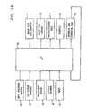
- the control circuit included in the apparatus is schematically illustrated in Fig. 16. It includes a microprocessor or controller 60 having a number of inputs, including the following: the input treatment criteria 61, specifying the conditions or other criteria governing the treatment of the hens; the egg sensor switches 23 for all the cages 2; the transponder reader 18, including its antenna 19 (not shown in Fig. 16); encoder 36 to indicate the instantaneous position of the carriage 30; and a timer 62.
- microprocessor 60 In response to the foregoing inputs, microprocessor 60 outputs control signals to control the following operations: drive motor 8 for the egg conveyor 7; drive motor 35 for the carriage 30; the piston/cylinder drive 6 for the drive shaft 5; and solenoid 40 carried by carriage 30 for actuating the ejector assembly of a cage is which the laying of an egg has been sensed.
- microprocessor 60 outputs at 63 various types of data relating to the individual hens of a flock that may be used for efficiently managing the flock of hens, as will be described more particularly below; this data is therefore returned as an input to the microprocessor.
- the apparatus is initially conditioned as shown in Figs. 8 and 13, wherein the traps 3 for all the cages 2 are in their open positions to permit the entry of a hen in each cage. Whenever a hen enters a cage, it closes trap 3 of the cage. As soon as the cage trap 3 is closed, it is latched in its closed condition by latching bail 51 engaging the end of extension 52 of trap 3 (Figs. 7 and 10), thereby preventing the hen from exiting the cage, as described in detail above. The hens may thus freely enter the cages for nesting purposes, but are prevented from exiting from the cage until the ejector assembly of the respective cage has been actuated.
- Motor 35 (Figs. 1 and 3) continuously drives carriage 30 back and forth across the line of cages. Normally, solenoid 40 is not energized, so that the actuator apex 43 (Figs. 4 and 5) between links 41 and 42 is below the rollers 44 of the ejector assemblies for all the cages, and therefore none of the ejector assemblies is coupled to the drive shaft 5.
- Drive shaft 5 is rotated as required, for example, periodically every ten minutes, first in one direction and then in the opposite direction, by piston-cylinder drive 6 (Fig. 1).
- piston-cylinder drive 6 Fig. 1
- none of the ejector assemblies is coupled to the drive shaft 5, and therefore none is actuated by it during the periodic actuations of the drive shaft 5.
- the downwardly inclined bottom wall 20 (Figs. 7, 8, and, 10 - 13) of the cage causes the egg to move by gravity onto the egg conveyor 7 (Figs. 1, and 10 - 13).
- This movement of the egg engages bail 22 (Fig. 2) for the respective cage, thereby actuating the egg sensor switch 23 (Figs. 2 and 16) of the respective cage.
- This information is fed to the controller 60, thereby enabling the controller 60 to identify in which cage an egg has been laid as soon as the egg passes onto the egg conveyor 7.
- Controller 60 by way of the carriage conveyor encoder 36 (Figs. 1, 3, and 16), can also identify the instantaneous position of the carriage 30. As soon as the carriage approaches a cage in which an egg has been laid or when another specified condition with respect to an individual hen has occurred, solenoid 40 of carriage 30 is energized: this raises the apex 43 (Figs. 4 and 5) between the two links 41 and 42 to engage roller 44 of the ejector assembly in the respective cage.
- roller 44 pivots the roller upwardly to cause lever 46 to release the end 48A of clutch bar 48, and thereby to permit the opposite end 48B of the clutch bar 48 to drop into engagement with clutch segment 49 carried by drive shaft 5, as previously described above with reference to Figs. 9, 10, and 11.
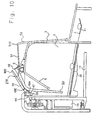
- Figs. 17 and 18 illustrate several possible modifications in the nesting apparatus of the present invention described above.
- the eggs are not removed from the cages by gravity, but rather by an egg-remover plate 100 pivotally mounted at the lower end of ejector frame 50, similar to the construction described in above cited U.S. Patent No. 4,188,911. Accordingly, as shown in Fig. 17, the egg conveyor belt 7 is located opposite to the hen entry / exit side of the cage where it is supported by a frame member 102. This is in contrast to the previously described location of the egg conveyor belt 7 shown in Figs. 10 - 13, wherein the egg conveyor belt 7 is located on the same side of the hen entry / exit side of the cage.
- FIG. 17 Another modification illustrated in Figs. 17 and 18 is that the movement of an egg from the cage onto the conveyor belt 7 is sensed by a flag 104 which is biased by a spring 106 to one of two stable positions.
- flag 104 is normally in the broken-line position illustrated in Fig. 18, but upon the movement of an egg onto the conveyor belt 7, the flag is moved by the egg to the actuated position shown in full lines in Fig. 18 to thereby provide an indication that an egg has been laid in the cage of the respective hen.
- This is sensed by an electrical switch sensor 108 (Fig. 17), carried by the carriage 30, which sensor also resets the flag 104 to its normal condition by actuating a solenoid plunger 110 (Fig. 18) to the side of the sensor.
- the nesting apparatus illustrated in the drawings can be used for efficiently controlling a flock of hens for producing maximum egg yield, by actuating the ejector mechanism of each cage, not periodically at pre-determined constant intervals as heretofore, but rather aperiodically when required, for example, shortly after the hen in a cage has laid an egg.
- the disclosed apparatus and corresponding method enable the egg yield from the flock to be even further increased by using the transponder 15 (Figs. 14 and 15) attached to each hen for monitoring the activities of the hens particularly when in the nesting cages.
- this transponder 15 permits the egg output of each hen to be monitored since it can identify the hen in each cage where an egg has been laid.
- the disclosed invention permits even more efficient monitoring and controlling individual hens of the flock.
- a particular hen has laid an egg within a preceding pre-determined time interval, for example, the preceding 24 hours, the chances are that the hen will not then lay another egg even if it entered a nesting cage; and therefore when such a hen has entered a nesting cage, the ejector assembly of the respective cage can be actuated to eject the hen immediately.
- the ejector assembly for the respective cage can be actuated, thereby enabling the time allowed for each hen to occupy a cage to be regulated individually.
- the disclosed invention particularly the provision of the transponders 15 identifying each hen and the eggs laid by the respective hens, permits data to be gathered for each individual hen or a group of hens to enable more efficient monitoring and controlling of the flock as a whole. For example, where the egg output of a particular hen is too low, this may indicate that the daily routine of the hen should be changed, or that the particular hen should no longer be used for egg laying purposes.
- a single egg sensor may be provided at a pre-determined location of the egg conveyor, and an encoder, or other means, may be used for determining the cage from which the egg entered the conveyor.
- other types of egg sensors could be used, for example optical sensors rather than electrical-switch sensors.
- the egg-sensor arrangement for automatically actuating the ejector assemblies could be used without the transponder arrangement for monitoring activities of the hens, and vice versa.
Landscapes
- Life Sciences & Earth Sciences (AREA)
- Environmental Sciences (AREA)
- Birds (AREA)
- Zoology (AREA)
- Animal Husbandry (AREA)
- Biodiversity & Conservation Biology (AREA)
- Housing For Livestock And Birds (AREA)
- Meat, Egg Or Seafood Products (AREA)
- Wrapping Of Specific Fragile Articles (AREA)
- Feeding And Watering For Cattle Raising And Animal Husbandry (AREA)
- Farming Of Fish And Shellfish (AREA)
- Radar Systems Or Details Thereof (AREA)
Applications Claiming Priority (3)
| Application Number | Priority Date | Filing Date | Title |
|---|---|---|---|
| IL11367595A IL113675A0 (en) | 1995-05-09 | 1995-05-09 | Hen nesting apparatus and method for utilizing such apparatus for brooding control |
| IL11367595 | 1995-05-09 | ||
| EP96915568A EP0909125B1 (en) | 1995-05-09 | 1996-05-08 | Hen nesting apparatus and brood control method |
Related Parent Applications (1)
| Application Number | Title | Priority Date | Filing Date |
|---|---|---|---|
| EP96915568A Division EP0909125B1 (en) | 1995-05-09 | 1996-05-08 | Hen nesting apparatus and brood control method |
Publications (3)
| Publication Number | Publication Date |
|---|---|
| EP1197142A2 EP1197142A2 (en) | 2002-04-17 |
| EP1197142A3 EP1197142A3 (en) | 2002-05-02 |
| EP1197142B1 true EP1197142B1 (en) | 2004-10-13 |
Family
ID=11067454
Family Applications (2)
| Application Number | Title | Priority Date | Filing Date |
|---|---|---|---|
| EP01129336A Expired - Lifetime EP1197142B1 (en) | 1995-05-09 | 1996-05-08 | Hen nesting apparatus and method utilizing such apparatus for identifying, monitoring and controlling individual hens of a flock |
| EP96915568A Expired - Lifetime EP0909125B1 (en) | 1995-05-09 | 1996-05-08 | Hen nesting apparatus and brood control method |
Family Applications After (1)
| Application Number | Title | Priority Date | Filing Date |
|---|---|---|---|
| EP96915568A Expired - Lifetime EP0909125B1 (en) | 1995-05-09 | 1996-05-08 | Hen nesting apparatus and brood control method |
Country Status (7)
| Country | Link |
|---|---|
| US (1) | US5950564A (enExample) |
| EP (2) | EP1197142B1 (enExample) |
| AU (1) | AU5731596A (enExample) |
| CA (1) | CA2220525C (enExample) |
| DE (2) | DE69633646D1 (enExample) |
| IL (1) | IL113675A0 (enExample) |
| WO (1) | WO1996035327A1 (enExample) |
Families Citing this family (10)
| Publication number | Priority date | Publication date | Assignee | Title |
|---|---|---|---|---|
| NL1005065C1 (nl) * | 1997-01-23 | 1998-07-27 | Jansen Maschf & Konstruktiebed | Werkwijze en inrichting voor het aan een ei koppelen van moederdierafhankelijke gegevens. |
| IL123007A0 (en) * | 1998-01-20 | 1998-08-16 | M G H Agricultural Cooperative | Apparatus and methods for management of flocks of layer fowl |
| KR100425930B1 (ko) * | 2002-01-16 | 2004-04-14 | 김진술 | 종란 자동 난상장치 |
| NL2009780C2 (nl) * | 2012-11-09 | 2014-05-12 | Uniq Ag | Legnest met uitdrijfsysteem. |
| ES2892310T3 (es) | 2017-01-27 | 2022-02-03 | Ctb Inc | Nido de puesta con sistema de expulsión del suelo con accionamiento por cremallera |
| NL2021254B1 (en) | 2018-07-05 | 2020-01-15 | Stichting Wageningen Res | Method and system for grading individual poultry hens in a flock |
| CN111134047B (zh) * | 2020-01-19 | 2024-11-15 | 浙江大学 | 笼养蛋鸡的蛋鸡区位产蛋性能监测方法与系统 |
| CN111838006B (zh) * | 2020-06-30 | 2022-06-21 | 民勤县中信牧业养殖专业合作社 | 羊群养殖个体分选系统 |
| CN113207746B (zh) * | 2021-04-19 | 2022-12-23 | 山西晋龙养殖股份有限公司 | 沿着养殖笼侧边循迹移动的鸡蛋自动装盒机构 |
| US20250234844A1 (en) * | 2024-01-24 | 2025-07-24 | Valco Industries, Inc. | Colony nest expeller |
Family Cites Families (22)
| Publication number | Priority date | Publication date | Assignee | Title |
|---|---|---|---|---|
| US1481684A (en) * | 1922-06-09 | 1924-01-22 | Butterfield Edwin Alfred Burr | Trap nest |
| GB378106A (en) * | 1931-05-11 | 1932-08-11 | George Doull | Improvements in apparatus for automatically registering the number of eggs laid by ahen |
| US2108287A (en) * | 1933-10-03 | 1938-02-15 | Orlando E Kellum | Means for checking and recording egg production of hens |
| US2204284A (en) * | 1937-08-10 | 1940-06-11 | Constantin A Sifakas | Poultry nest |
| IL52211A (en) * | 1977-06-01 | 1979-11-30 | Givat Chaim Ichud | Enclosure device for encouraging the laying of eggs by domestic fowls particularly turkeys |
| US4512096A (en) * | 1981-10-19 | 1985-04-23 | Dairy Systems, Inc. | Animal identification band and method and means for permanently fastening same |
| US4354098A (en) * | 1981-11-03 | 1982-10-12 | Chore-Time Equipment, Inc. | Egg counter |
| US4381732A (en) * | 1981-11-09 | 1983-05-03 | Huisinga Theodore G | Poultry nest |
| IL67832A (en) * | 1983-02-04 | 1985-11-29 | Mgh Automation Systems | Egg-collection system |
| US4597495A (en) * | 1985-04-25 | 1986-07-01 | Knosby Austin T | Livestock identification system |
| IL77833A (en) * | 1986-02-10 | 1988-11-30 | Mgh Automation Systems | Nest trap for laying hens |
| US4798175A (en) * | 1986-10-09 | 1989-01-17 | Alfa-Laval Agri, Inc. | Electronic identification system |
| NL8802777A (nl) * | 1988-11-11 | 1990-06-01 | Elite Nv | Inrichting voor het verzamelen van eieren. |
| US5069165A (en) * | 1990-10-12 | 1991-12-03 | Victor Rousseau | Livestock feeder system |
| NL9002424A (nl) * | 1990-11-08 | 1992-06-01 | Nedap Nv | Bevestigingsring voor het aanbrengen van een voorwerp of nummer aan een poot (been) van een dier. |
| NL9002465A (nl) * | 1990-11-12 | 1992-06-01 | Nedap Nv | Voersysteem voor dieren. |
| US5125362A (en) * | 1990-12-10 | 1992-06-30 | Erickson Automation, A Partnership | Turkey nest timer |
| US5143021A (en) * | 1991-09-19 | 1992-09-01 | Matti Shaley | Automatic enclosure nest for domestic fowl |
| US5222459A (en) * | 1992-05-21 | 1993-06-29 | Shenandoah Manufacturing Company, Inc. | Automatic turkey nesting apparatus |
| NL9201625A (nl) * | 1992-09-21 | 1994-04-18 | Nedap Nv | Identificatie- en weeginrichting voor identificatie van groepen dieren. |
| NL9301317A (nl) * | 1993-07-28 | 1995-02-16 | Lely Nv C Van Der | Inrichting voor het automatisch melken van dieren. |
| US5628284A (en) * | 1995-06-06 | 1997-05-13 | Alfa Laval Agri, Inc. | Livestock cutter gate apparatus |
-
1995
- 1995-05-09 IL IL11367595A patent/IL113675A0/xx unknown
-
1996
- 1996-05-08 EP EP01129336A patent/EP1197142B1/en not_active Expired - Lifetime
- 1996-05-08 DE DE69633646T patent/DE69633646D1/de not_active Expired - Lifetime
- 1996-05-08 WO PCT/US1996/006441 patent/WO1996035327A1/en not_active Ceased
- 1996-05-08 EP EP96915568A patent/EP0909125B1/en not_active Expired - Lifetime
- 1996-05-08 AU AU57315/96A patent/AU5731596A/en not_active Abandoned
- 1996-05-08 DE DE69624510T patent/DE69624510T2/de not_active Expired - Fee Related
- 1996-05-08 US US08/952,315 patent/US5950564A/en not_active Expired - Fee Related
- 1996-05-08 CA CA002220525A patent/CA2220525C/en not_active Expired - Fee Related
Also Published As
| Publication number | Publication date |
|---|---|
| AU5731596A (en) | 1996-11-29 |
| US5950564A (en) | 1999-09-14 |
| CA2220525C (en) | 2005-06-28 |
| DE69624510T2 (de) | 2003-06-26 |
| DE69633646D1 (de) | 2004-11-18 |
| IL113675A0 (en) | 1995-08-31 |
| CA2220525A1 (en) | 1996-11-14 |
| EP1197142A2 (en) | 2002-04-17 |
| WO1996035327A1 (en) | 1996-11-14 |
| EP0909125B1 (en) | 2002-10-23 |
| EP0909125A4 (enExample) | 1999-04-21 |
| DE69624510D1 (de) | 2002-11-28 |
| EP1197142A3 (en) | 2002-05-02 |
| EP0909125A1 (en) | 1999-04-21 |
Similar Documents
| Publication | Publication Date | Title |
|---|---|---|
| EP1197142B1 (en) | Hen nesting apparatus and method utilizing such apparatus for identifying, monitoring and controlling individual hens of a flock | |
| EP1085802B2 (en) | Arrangement and method for housing lactating animals | |
| EP0499428B1 (en) | Livestock sorting system | |
| EP0512096B1 (en) | Method of feeding animals and apparatus suitable for carrying out said method | |
| US4617876A (en) | Animal identification and control system | |
| DE69637170T2 (de) | Zonenbasierte güterordnung und steuersystem | |
| US6341582B1 (en) | Livestock sorting system | |
| US7721675B2 (en) | Method for providing information on the occupancy of milking stations of a milking system | |
| EP0589534B1 (en) | Detection system for selectively distinguishing a number of groups of animals | |
| DE102019110304A1 (de) | Vorrichtung, Bausatz und Verfahren zur berührungslosen Ermittlung der Körpertemperatur eines Nutztieres | |
| EP3466253B1 (de) | Vorrichtung für die auffindung von objekten in einem tierstall | |
| NL1005065C1 (nl) | Werkwijze en inrichting voor het aan een ei koppelen van moederdierafhankelijke gegevens. | |
| US6167317A (en) | Apparatus and methods for management of flocks of layer fowl | |
| EP0753249B2 (en) | A method of milking animals | |
| EP1169917A1 (en) | Method and apparatus for determining animal movements | |
| NL1002173C2 (nl) | Werkwijze voor het automatisch melken van dieren. | |
| KR102605937B1 (ko) | 축산 동물의 행동 패턴을 기반으로 한 무리 서열 데이터 검출 방법 | |
| WO2025252990A1 (en) | System and method for central egg collection | |
| WO1991016817A1 (en) | Apparatus for setting and hauling long fishing lines | |
| WO2025144060A1 (en) | A system for monitoring animal migration | |
| NL1032150C1 (nl) | Inrichting voor het automatisch melken van een dier. | |
| Moller et al. | Automated system for measuring breeding burrows entry and exit by sooty shearwaters (Puffinus griseus) | |
| IL111397A (en) | A sorting system provides |
Legal Events
| Date | Code | Title | Description |
|---|---|---|---|
| PUAI | Public reference made under article 153(3) epc to a published international application that has entered the european phase |
Free format text: ORIGINAL CODE: 0009012 |
|
| PUAL | Search report despatched |
Free format text: ORIGINAL CODE: 0009013 |
|
| AC | Divisional application: reference to earlier application |
Ref document number: 909125 Country of ref document: EP |
|
| AK | Designated contracting states |
Kind code of ref document: A2 Designated state(s): DE FR GB IE IT |
|
| AK | Designated contracting states |
Kind code of ref document: A3 Designated state(s): DE FR GB IE IT |
|
| RIC1 | Information provided on ipc code assigned before grant |
Free format text: 7A 01K 31/16 A, 7A 01K 11/00 B |
|
| 17P | Request for examination filed |
Effective date: 20020603 |
|
| 17Q | First examination report despatched |
Effective date: 20021031 |
|
| AKX | Designation fees paid |
Free format text: DE FR GB IE IT |
|
| GRAP | Despatch of communication of intention to grant a patent |
Free format text: ORIGINAL CODE: EPIDOSNIGR1 |
|
| GRAS | Grant fee paid |
Free format text: ORIGINAL CODE: EPIDOSNIGR3 |
|
| GRAA | (expected) grant |
Free format text: ORIGINAL CODE: 0009210 |
|
| AC | Divisional application: reference to earlier application |
Ref document number: 0909125 Country of ref document: EP Kind code of ref document: P |
|
| AK | Designated contracting states |
Kind code of ref document: B1 Designated state(s): DE FR GB IE IT |
|
| PG25 | Lapsed in a contracting state [announced via postgrant information from national office to epo] |
Ref country code: IT Free format text: LAPSE BECAUSE OF FAILURE TO SUBMIT A TRANSLATION OF THE DESCRIPTION OR TO PAY THE FEE WITHIN THE PRESCRIBED TIME-LIMIT;WARNING: LAPSES OF ITALIAN PATENTS WITH EFFECTIVE DATE BEFORE 2007 MAY HAVE OCCURRED AT ANY TIME BEFORE 2007. THE CORRECT EFFECTIVE DATE MAY BE DIFFERENT FROM THE ONE RECORDED. Effective date: 20041013 |
|
| REG | Reference to a national code |
Ref country code: GB Ref legal event code: FG4D |
|
| REG | Reference to a national code |
Ref country code: IE Ref legal event code: FG4D |
|
| REF | Corresponds to: |
Ref document number: 69633646 Country of ref document: DE Date of ref document: 20041118 Kind code of ref document: P |
|
| PG25 | Lapsed in a contracting state [announced via postgrant information from national office to epo] |
Ref country code: DE Free format text: LAPSE BECAUSE OF FAILURE TO SUBMIT A TRANSLATION OF THE DESCRIPTION OR TO PAY THE FEE WITHIN THE PRESCRIBED TIME-LIMIT Effective date: 20050114 |
|
| PG25 | Lapsed in a contracting state [announced via postgrant information from national office to epo] |
Ref country code: GB Free format text: LAPSE BECAUSE OF NON-PAYMENT OF DUE FEES Effective date: 20050508 |
|
| PG25 | Lapsed in a contracting state [announced via postgrant information from national office to epo] |
Ref country code: IE Free format text: LAPSE BECAUSE OF NON-PAYMENT OF DUE FEES Effective date: 20050509 |
|
| PLBE | No opposition filed within time limit |
Free format text: ORIGINAL CODE: 0009261 |
|
| STAA | Information on the status of an ep patent application or granted ep patent |
Free format text: STATUS: NO OPPOSITION FILED WITHIN TIME LIMIT |
|
| ET | Fr: translation filed | ||
| 26N | No opposition filed |
Effective date: 20050714 |
|
| GBPC | Gb: european patent ceased through non-payment of renewal fee |
Effective date: 20050508 |
|
| REG | Reference to a national code |
Ref country code: IE Ref legal event code: MM4A |
|
| PGFP | Annual fee paid to national office [announced via postgrant information from national office to epo] |
Ref country code: FR Payment date: 20060519 Year of fee payment: 11 |
|
| REG | Reference to a national code |
Ref country code: FR Ref legal event code: ST Effective date: 20080131 |
|
| PG25 | Lapsed in a contracting state [announced via postgrant information from national office to epo] |
Ref country code: FR Free format text: LAPSE BECAUSE OF NON-PAYMENT OF DUE FEES Effective date: 20070531 |