EP1197142B1 - Hen nesting apparatus and method utilizing such apparatus for identifying, monitoring and controlling individual hens of a flock - Google Patents
Hen nesting apparatus and method utilizing such apparatus for identifying, monitoring and controlling individual hens of a flock Download PDFInfo
- Publication number
- EP1197142B1 EP1197142B1 EP01129336A EP01129336A EP1197142B1 EP 1197142 B1 EP1197142 B1 EP 1197142B1 EP 01129336 A EP01129336 A EP 01129336A EP 01129336 A EP01129336 A EP 01129336A EP 1197142 B1 EP1197142 B1 EP 1197142B1
- Authority
- EP
- European Patent Office
- Prior art keywords
- hen
- cage
- egg
- ejector
- cages
- Prior art date
- Legal status (The legal status is an assumption and is not a legal conclusion. Google has not performed a legal analysis and makes no representation as to the accuracy of the status listed.)
- Expired - Lifetime
Links
Images


Classifications
-
- A—HUMAN NECESSITIES
- A01—AGRICULTURE; FORESTRY; ANIMAL HUSBANDRY; HUNTING; TRAPPING; FISHING
- A01K—ANIMAL HUSBANDRY; CARE OF BIRDS, FISHES, INSECTS; FISHING; REARING OR BREEDING ANIMALS, NOT OTHERWISE PROVIDED FOR; NEW BREEDS OF ANIMALS
- A01K31/00—Housing birds
- A01K31/14—Nest-boxes, e.g. for singing birds or the like
- A01K31/16—Laying nests for poultry; Egg collecting
-
- A—HUMAN NECESSITIES
- A01—AGRICULTURE; FORESTRY; ANIMAL HUSBANDRY; HUNTING; TRAPPING; FISHING
- A01K—ANIMAL HUSBANDRY; CARE OF BIRDS, FISHES, INSECTS; FISHING; REARING OR BREEDING ANIMALS, NOT OTHERWISE PROVIDED FOR; NEW BREEDS OF ANIMALS
- A01K1/00—Housing animals; Equipment therefor
- A01K1/0005—Stable partitions
- A01K1/0017—Gates, doors
- A01K1/0029—Crowding gates or barriers
Definitions
- the present invention relates to a hen nesting apparatus, and to a method utilizing such apparatus for identifying, monitoring, and controlling individual hens of a flock, such as for broody (nesting) control.
- the invention is particularly, but not exclusively, useful with respect to turkey hens and is therefore described below in connection with this application.
- Nesting apparatuses are known, for example, as described in Israel Patent No. 52211 (U.S. Patent No. 4,188,911), issued to Rafaely, for turkey hens which include a line of nesting cages and an ejector assembly in each cage actuatable to eject a hen from the cage.
- the ejector assemblies of all the cages are actuated at the same times according to fixed intervals, for example, at 45 minute intervals.
- Such constructions therefore do not maximize the use of the nesting cages.
- the current methods of broody control generally deal with the flocks as a whole, and therefore do not maximize the egg output of the individual hens within a flock.
- An object of the present invention is to provide a hen nesting apparatus having advantages in the above respects.
- Another object of the invention is to provide a hen nesting apparatus, and also a method utilizing such apparatus for identifying, monitoring, and controlling individual hens of a flock, such as for controlling the brooding of a flock of hens in order to maximize their egg output.
- a hen nesting apparatus comprising: a transponder attachable to each hen effective, upon being interrogated by an antenna, to transmit a signal identifying the respective hen; a line of nesting cages; a carriage movable along a path traversing the line of cages; a carriage drive for driving the carriage; an encoder for continuously indicating the instantaneous position of the carriage with respect to the cages traversed by the carriage; and a receiver for receiving the signals from the transponder and for thereby identifying the hens in the cages as traversed by the carriage.
- a method for controlling individual hens of a flock comprising: providing the flock of hens with a line of nesting cages each including an ejector member actuatable to eject a hen therefrom; sensing the occurrence of a specified condition with respect to the individual hens; controlling the ejector assembly of a nesting cage occupied by a hen in response to sensing the occurrence of the specified condition with respect to the respective hen; attaching to each hen a transponder effective, upon being interrogated, to transmit a signal identifying the respective hen; moving an antenna along the line of nesting cases for interrogating the transponders carried by the hens in the cages; receiving identification signals from the transponders as they are interrogated by the antenna; determining the instantaneous position of the antenna at the time a signal is received from an interrogated transponder, to thereby identify the hen in each cage occupied by a hen; and upon determining
- a method for identifying individual hens of a flock comprising: providing the flock of hens with a line of nesting cages; attaching to each hen a transponder effective, upon being interrogated, to transmit a signal identifying the respective hen; moving an antenna along the line of the nesting cages for interrogating the transponders carried by the hens in the cages; receiving identification signals from the transponders as they are interrogated by the antenna; and determining the instantaneous position of the antenna at the time a signal is received from an interrogated transponder to thereby identify the hen in each cage occupied by a hen.
- the apparatus and method of the present invention enable individual hens of a flock to be identified, monitored, and controlled, for producing a maximum egg output from the flock of hens. Further features and advantages of the invention are apparent from the description below.
- the present invention relates to a hen nesting apparatus, and to a method utilizing such apparatus for identifying, monitoring, and controlling individual hens of a flock, such as for broody (nesting) control.
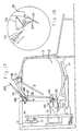
- the nesting apparatus shown in Figs. 1 - 16 illustrates a preferred embodiment of the invention for identifying, monitoring, and controlling individual hens of a flock, particularly a flock of turkey hens, for producing a maximum egg output from the flock of hens.
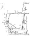
- the apparatus includes a line of nesting cages 2 for the hens to shelter them from disturbances at the time of nesting.
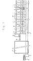
- each cage includes a trap 3 which is normally open and automatically closes when a hen enters the cage, and an ejector member in the form of an ejector frame 50 which is actuated in order to gently eject the hen from the cage so as to permit the cage to be used for other hens.
- All the ejector frames 50 in the line of cages 2 are actuated by a common drive shaft 5 which is rotated in one direction by the forward movement of a pneumatic piston-cylinder drive 6 (Fig. 1), and rotated in the return direction by the return movement of the piston-cylinder drive 6 .
- the eggs are collected from all the cages 2 by a conveyor belt 7 which extends along one side of the line of nesting cages 2.
- the conveyor belt 7 is driven by a motor 8 carried by a base 9 at one end of the apparatus so that the conveyor belt traverses the line of cages 2 in order to receive the eggs and to convey them to a collection table 10.
- the cages 2 are defined by a plurality of partition plates 11 mounted to a frame structure 12.
- the drive shaft 5 is rotatably supported by the frame structure to overlie the upper ends of all the cages 2.
- the ejector member of each cage is individually controlled to enable the ejector member of a particular cage to be individually actuated independently of the ejector members of the other cages when an egg has been laid in the respective cage, and/or when another specified condition with respect to an individual hen has occurred. Accordingly, the apparatus and method of the present invention enable individual hens of a flock to be identified, monitored, and controlled, for producing a maximum egg output from the flock of hens.
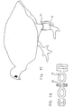
- each hen is provided with a transponder, generally designated 15 (Figs. 14 and 15), attached to a retaining band 16 applied to a leg of the hen.
- Each transponder 15 includes an identification of the respective hen and cooperates with a reader 18 (shown in Figs. 1, 4, 10 - 13, 16, and 17) carrying an antenna 19 (Figs. 10 - 13, and 17) which traverses the line of nesting cages in close proximity to the transponders 15 of the hens within the cages.
- the reader 18 interrogates the transponders 15 in sequence by transmitting a power burst by way of antenna 19.
- the power burst charges each transponder 15 and enables it to transmit a return signal that carries the hen identification and/or other data stored in the transponder 15 for the respective hen.
- transponder/reader system that may be used is that supplied by Texas Instruments under the trademark "TIRIS"; it is based on low-frequency FM transmission techniques.
- each cage 2 is inclined downwardly towards the egg conveyor 7 so that any egg laid in the respective cage moves by gravity onto the conveyor 7.
- the egg conveyor 7 is supported by a frame member 21 below the respective end of the cage bottom wall 20.
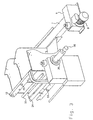
- an egg sensor in the form of a bail-shaped member 22 is pivotally mounted across the respective end of each cage, adjacent to the egg conveyor 7 so that this member is engaged and pivoted by an egg moving by gravity from the cage bottom wall 20 (Figs. 7, 8, and, 10 - 13) onto the egg conveyor 7.
- the bail 22 actuates an electrical switch 23, which thereby provides a signal to a controller 60 (Fig. 16) that an egg has been laid in the respective cage.
- Each cage is provided with an ejector assembly, which includes the previously mentioned ejector frame 50, actuated when the egg sensor (electrical switch 23 actuated by bail 22 ) has sensed that a hen has laid an egg in the respective cage and/or when another specified condition with respect to an individual hen has occurred.
- the ejector actuator system actuates the ejector assembly of the respective cage to eject the hen then in the cage.
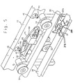
- the common actuator system for all the ejector bars includes a carriage, generally designated 30, supported at its opposite ends by two upper rollers 31 and a lower roller 32 movable along opposite sides of a guide rod 33 adjacent to the upper ends of all the cages 2 (Figs. 1 and 2).
- Carriage 30 is driven by a closed-loop belt 34 rotated by a motor 35 (Figs. 1 and 3) supported at one end of the frame structure 12.
- An encoder 36 (Figs. 1 and 3) provides an electrical indication of the instantaneous position of the carriage 30.
- Carriage 30 is coupled to the closed-loop belt 34 by a two-part slip-coupling, best seen in Figs. 5 and 6.
- One part 37 is secured to the carriage 30, for example, as shown at 37A in Fig. 5, and includes a pair of rollers 37B (shown in Fig. 6; location only shown in Fig. 5) receivable within recesses 38A of the second part 38 fixed to the belt 34.
- rollers 37B are seated in recess 38A to thereby couple the carriage 30 to the belt 34; however, should movement of the carriage 30 be blocked by an obstacle, roller 37B will unseat from recesses 38A, to thereby prevent damage to the belt 34 or to motor 35 driving it.
- carriage 30 carries a solenoid 40 which, in this embodiment, is energized by the actuation of one of the egg sensors (switch 23, Fig. 2) when an egg has been laid in a particular cage or when another specified condition with respect to a particular hen has occurred.
- Solenoid 40 is coupled to one end of a pivotal link 41.
- the opposite end of link 41 is pivotally coupled to a second link 42 also pivotally mounted to the carriage 30.
- the two links 41 and 42 are pivotally mounted at an angle to each other such that they form an apex at their juncture 43 which is at a relatively low position when solenoid 40 is not energized, but which is moved to a higher position when the solenoid is energized.
- the apex 43 between the two links 41 and 42 serves as an actuator for actuating the ejector assembly of a particular cage when a hen has laid an egg therein as sensed by the egg sensor switch 23, and/or when another specified condition has occurred.
- the ejector assembly of each cage includes a roller 44 projecting through an opening 45 in the apparatus frame 12.
- solenoid 40 is not energized, so that the apex 43 between the two links 41 and 42 passes under all the rollers 44; however, when solenoid 40 is energized, apex 43 is moved upwardly to engage the next roller 44 which it encounters during its movement by carriage 30 across the line of cages.
- roller 44 is coupled to one end of a lever 46 formed with a shoulder 47.
- This shoulder normally seats one end 48A of a clutch bar 48 pivotally mounted at point 48C to the ejector frame 50 such that the opposite end 48B of the clutch bar 48 is normally raised above a clutch segment 49 secured to the drive shaft 5.
- lever 46 is pivoted to permit clutch bar 48 to pivot clockwise (Fig. 10), to bring its end 48B into alignment with clutch segment 49 (Fig. 11), and thereby to couple the clutch bar 48 to the drive shaft 5.
- clutch bar 48 is pivotally mounted at 48C to the ejector frame 50 such that when the clutch bar is coupled to drive shaft 5 it pivots the ejector frame 50.
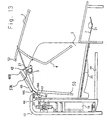
- the ejector frame 50 pivotally mounts ejector bar 4 and also trap 3.
- the arrangement is such that when the ejector frame 50 is pivoted in a counter-clockwise direction, as shown in Figs. 11 - 13, the ejector frame 50 moves the ejector bar 4 towards the entrance of the respective cage, to eject the hen therefrom, and at the same time moves ejector bar 4 causing the trap 3 to its open position to thereby permit another hen to enter the cage.
- drive shaft 5 returns the ejector frame 50 to its initial position, and the clutch bar 48 is relatched in its normal position (Fig. 13) with its end 48A seated against shoulder 47 and lever 46, assuming that its roller 44 has returned to its lower position.
- the cage from which a hen has been ejected is thus open to enable another hen to enter. When another hen does enter, it closes trap 3 to prevent another hen from entering.
- the ejector assembly of each cage may include a latching member 51, in the form of a bail pivotally mounted to the ejector frame 50 at one end 51A, and cooperable at its opposite end with an extension 52 in trap 3.
- latching bail 51 engages the upper end of the trap extension 52, at point 51B, to thereby prevent the trap from being opened by the hen; but, as soon as the ejector assembly of the respective cage has been actuated, latching bail 51 is pivoted, at point 51B, out of engagement with the end of trap extension 52, as shown in Fig. 8, to permit the trap to be opened at the time the ejector frame 50 is actuated, as shown in Figs. 12 and 13.
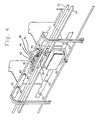
- the apparatus frame 12 further includes a second series of openings 55 (Fig. 4) one for each cage 2. These openings are cooperable with an optical detector (not shown) carried by reader 18 for calibrating purposes.
- encoder 36 (Figs. 1 and 3), which identifies the position of the carriage 30 with respect to the cages 2, may be pre-calibrated by openings 55 at known locations with respect to each of the cages.
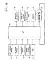
- the control circuit included in the apparatus is schematically illustrated in Fig. 16. It includes a microprocessor or controller 60 having a number of inputs, including the following: the input treatment criteria 61, specifying the conditions or other criteria governing the treatment of the hens; the egg sensor switches 23 for all the cages 2; the transponder reader 18, including its antenna 19 (not shown in Fig. 16); encoder 36 to indicate the instantaneous position of the carriage 30; and a timer 62.
- microprocessor 60 In response to the foregoing inputs, microprocessor 60 outputs control signals to control the following operations: drive motor 8 for the egg conveyor 7; drive motor 35 for the carriage 30; the piston/cylinder drive 6 for the drive shaft 5; and solenoid 40 carried by carriage 30 for actuating the ejector assembly of a cage is which the laying of an egg has been sensed.
- microprocessor 60 outputs at 63 various types of data relating to the individual hens of a flock that may be used for efficiently managing the flock of hens, as will be described more particularly below; this data is therefore returned as an input to the microprocessor.
- the apparatus is initially conditioned as shown in Figs. 8 and 13, wherein the traps 3 for all the cages 2 are in their open positions to permit the entry of a hen in each cage. Whenever a hen enters a cage, it closes trap 3 of the cage. As soon as the cage trap 3 is closed, it is latched in its closed condition by latching bail 51 engaging the end of extension 52 of trap 3 (Figs. 7 and 10), thereby preventing the hen from exiting the cage, as described in detail above. The hens may thus freely enter the cages for nesting purposes, but are prevented from exiting from the cage until the ejector assembly of the respective cage has been actuated.
- Motor 35 (Figs. 1 and 3) continuously drives carriage 30 back and forth across the line of cages. Normally, solenoid 40 is not energized, so that the actuator apex 43 (Figs. 4 and 5) between links 41 and 42 is below the rollers 44 of the ejector assemblies for all the cages, and therefore none of the ejector assemblies is coupled to the drive shaft 5.
- Drive shaft 5 is rotated as required, for example, periodically every ten minutes, first in one direction and then in the opposite direction, by piston-cylinder drive 6 (Fig. 1).
- piston-cylinder drive 6 Fig. 1
- none of the ejector assemblies is coupled to the drive shaft 5, and therefore none is actuated by it during the periodic actuations of the drive shaft 5.
- the downwardly inclined bottom wall 20 (Figs. 7, 8, and, 10 - 13) of the cage causes the egg to move by gravity onto the egg conveyor 7 (Figs. 1, and 10 - 13).
- This movement of the egg engages bail 22 (Fig. 2) for the respective cage, thereby actuating the egg sensor switch 23 (Figs. 2 and 16) of the respective cage.
- This information is fed to the controller 60, thereby enabling the controller 60 to identify in which cage an egg has been laid as soon as the egg passes onto the egg conveyor 7.
- Controller 60 by way of the carriage conveyor encoder 36 (Figs. 1, 3, and 16), can also identify the instantaneous position of the carriage 30. As soon as the carriage approaches a cage in which an egg has been laid or when another specified condition with respect to an individual hen has occurred, solenoid 40 of carriage 30 is energized: this raises the apex 43 (Figs. 4 and 5) between the two links 41 and 42 to engage roller 44 of the ejector assembly in the respective cage.
- roller 44 pivots the roller upwardly to cause lever 46 to release the end 48A of clutch bar 48, and thereby to permit the opposite end 48B of the clutch bar 48 to drop into engagement with clutch segment 49 carried by drive shaft 5, as previously described above with reference to Figs. 9, 10, and 11.
- Figs. 17 and 18 illustrate several possible modifications in the nesting apparatus of the present invention described above.
- the eggs are not removed from the cages by gravity, but rather by an egg-remover plate 100 pivotally mounted at the lower end of ejector frame 50, similar to the construction described in above cited U.S. Patent No. 4,188,911. Accordingly, as shown in Fig. 17, the egg conveyor belt 7 is located opposite to the hen entry / exit side of the cage where it is supported by a frame member 102. This is in contrast to the previously described location of the egg conveyor belt 7 shown in Figs. 10 - 13, wherein the egg conveyor belt 7 is located on the same side of the hen entry / exit side of the cage.
- FIG. 17 Another modification illustrated in Figs. 17 and 18 is that the movement of an egg from the cage onto the conveyor belt 7 is sensed by a flag 104 which is biased by a spring 106 to one of two stable positions.
- flag 104 is normally in the broken-line position illustrated in Fig. 18, but upon the movement of an egg onto the conveyor belt 7, the flag is moved by the egg to the actuated position shown in full lines in Fig. 18 to thereby provide an indication that an egg has been laid in the cage of the respective hen.
- This is sensed by an electrical switch sensor 108 (Fig. 17), carried by the carriage 30, which sensor also resets the flag 104 to its normal condition by actuating a solenoid plunger 110 (Fig. 18) to the side of the sensor.
- the nesting apparatus illustrated in the drawings can be used for efficiently controlling a flock of hens for producing maximum egg yield, by actuating the ejector mechanism of each cage, not periodically at pre-determined constant intervals as heretofore, but rather aperiodically when required, for example, shortly after the hen in a cage has laid an egg.
- the disclosed apparatus and corresponding method enable the egg yield from the flock to be even further increased by using the transponder 15 (Figs. 14 and 15) attached to each hen for monitoring the activities of the hens particularly when in the nesting cages.
- this transponder 15 permits the egg output of each hen to be monitored since it can identify the hen in each cage where an egg has been laid.
- the disclosed invention permits even more efficient monitoring and controlling individual hens of the flock.
- a particular hen has laid an egg within a preceding pre-determined time interval, for example, the preceding 24 hours, the chances are that the hen will not then lay another egg even if it entered a nesting cage; and therefore when such a hen has entered a nesting cage, the ejector assembly of the respective cage can be actuated to eject the hen immediately.
- the ejector assembly for the respective cage can be actuated, thereby enabling the time allowed for each hen to occupy a cage to be regulated individually.
- the disclosed invention particularly the provision of the transponders 15 identifying each hen and the eggs laid by the respective hens, permits data to be gathered for each individual hen or a group of hens to enable more efficient monitoring and controlling of the flock as a whole. For example, where the egg output of a particular hen is too low, this may indicate that the daily routine of the hen should be changed, or that the particular hen should no longer be used for egg laying purposes.
- a single egg sensor may be provided at a pre-determined location of the egg conveyor, and an encoder, or other means, may be used for determining the cage from which the egg entered the conveyor.
- other types of egg sensors could be used, for example optical sensors rather than electrical-switch sensors.
- the egg-sensor arrangement for automatically actuating the ejector assemblies could be used without the transponder arrangement for monitoring activities of the hens, and vice versa.
Description
- The present invention relates to a hen nesting apparatus, and to a method utilizing such apparatus for identifying, monitoring, and controlling individual hens of a flock, such as for broody (nesting) control. The invention is particularly, but not exclusively, useful with respect to turkey hens and is therefore described below in connection with this application.
- Nesting apparatuses are known, for example, as described in Israel Patent No. 52211 (U.S. Patent No. 4,188,911), issued to Rafaely, for turkey hens which include a line of nesting cages and an ejector assembly in each cage actuatable to eject a hen from the cage. In these known constructions, the ejector assemblies of all the cages are actuated at the same times according to fixed intervals, for example, at 45 minute intervals. Such constructions therefore do not maximize the use of the nesting cages. Moreover, the current methods of broody control generally deal with the flocks as a whole, and therefore do not maximize the egg output of the individual hens within a flock.
- An object of the present invention is to provide a hen nesting apparatus having advantages in the above respects.
- Another object of the invention is to provide a hen nesting apparatus, and also a method utilizing such apparatus for identifying, monitoring, and controlling individual hens of a flock, such as for controlling the brooding of a flock of hens in order to maximize their egg output.
- According to one aspect of the present invention, there is provided a hen nesting apparatus, comprising: a transponder attachable to each hen effective, upon being interrogated by an antenna, to transmit a signal identifying the respective hen; a line of nesting cages; a carriage movable along a path traversing the line of cages; a carriage drive for driving the carriage; an encoder for continuously indicating the instantaneous position of the carriage with respect to the cages traversed by the carriage; and a receiver for receiving the signals from the transponder and for thereby identifying the hens in the cages as traversed by the carriage.
- According to another aspect of the present invention, there is provided a method for controlling individual hens of a flock, comprising: providing the flock of hens with a line of nesting cages each including an ejector member actuatable to eject a hen therefrom; sensing the occurrence of a specified condition with respect to the individual hens; controlling the ejector assembly of a nesting cage occupied by a hen in response to sensing the occurrence of the specified condition with respect to the respective hen; attaching to each hen a transponder effective, upon being interrogated, to transmit a signal identifying the respective hen; moving an antenna along the line of nesting cases for interrogating the transponders carried by the hens in the cages; receiving identification signals from the transponders as they are interrogated by the antenna; determining the instantaneous position of the antenna at the time a signal is received from an interrogated transponder, to thereby identify the hen in each cage occupied by a hen; and upon determining that a hen in a particular cage has already laid an egg in one of the cages within a pre-determined time period, actuating the ejector assembly to eject the hen from the respective cage.
- According to another aspect of the present invention, there is provided a method for identifying individual hens of a flock, comprising: providing the flock of hens with a line of nesting cages; attaching to each hen a transponder effective, upon being interrogated, to transmit a signal identifying the respective hen; moving an antenna along the line of the nesting cages for interrogating the transponders carried by the hens in the cages; receiving identification signals from the transponders as they are interrogated by the antenna; and determining the instantaneous position of the antenna at the time a signal is received from an interrogated transponder to thereby identify the hen in each cage occupied by a hen.
- The invention is defined in appended
claims 1 and 7. - As will be described more particularly below, the apparatus and method of the present invention enable individual hens of a flock to be identified, monitored, and controlled, for producing a maximum egg output from the flock of hens. Further features and advantages of the invention are apparent from the description below.
- The invention is herein described, by way of example only, with reference to the accompanying drawings, wherein:
- Fig. 1 is a top plan view illustrating one form of a nesting apparatus constructed in accordance with the present invention;
- Fig. 2 is an enlarged perspective view of a portion of the apparatus of Fig. 1 from the egg conveyor side of the apparatus;
- Fig. 3 is a perspective view of a portion of the apparatus of Fig. 1 from the side opposite to that of the egg conveyor;
- Fig. 4 is a perspective view of another portion of the apparatus from the same side as in Fig. 3;
- Fig. 5 is an enlarged perspective view of a portion of the apparatus seen in Fig. 4;
- Fig. 6 is an exploded view illustrating a slip-coupling used in the portion of the apparatus shown in Figs. 4 and 5;
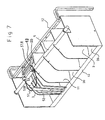
- Fig. 7 is a perspective view illustrating a plurality of the cages and particularly the ejector assembly of one of the cages in its non-actuated condition;
- Fig. 8 is a view similar to that of Fig. 7, but showing the ejector assembly in its actuated condition;
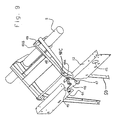
- Fig. 9 is a perspective view more particularly illustrating the main elements of the ejector actuator system;
- Figs. 10 - 13, respectively, are side elevational views illustrating different phases of the operation of the ejector assembly and its actuator system;
- Fig. 14 illustrates the transponder;
- Fig. 15 illustrates the manner of attachment of the transponder to a hen;
- Fig. 16 is a block diagram schematically illustrating the overall electrical control system;
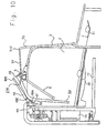
- Fig. 17 is a side elevational view, corresponding to that of Fig. 10, but illustrating a modification in the construction of the apparatus; and
- Fig. 18 is an enlarged view of the egg flagging arrangement included in the apparatus of Fig. 17.
-
- The present invention relates to a hen nesting apparatus, and to a method utilizing such apparatus for identifying, monitoring, and controlling individual hens of a flock, such as for broody (nesting) control.
- The nesting apparatus shown in Figs. 1 - 16 illustrates a preferred embodiment of the invention for identifying, monitoring, and controlling individual hens of a flock, particularly a flock of turkey hens, for producing a maximum egg output from the flock of hens. For this purpose, the apparatus includes a line of nesting
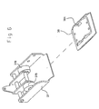
cages 2 for the hens to shelter them from disturbances at the time of nesting. As shown particularly in Figs. 10 - 13, each cage includes atrap 3 which is normally open and automatically closes when a hen enters the cage, and an ejector member in the form of anejector frame 50 which is actuated in order to gently eject the hen from the cage so as to permit the cage to be used for other hens. All theejector frames 50 in the line ofcages 2 are actuated by acommon drive shaft 5 which is rotated in one direction by the forward movement of a pneumatic piston-cylinder drive 6 (Fig. 1), and rotated in the return direction by the return movement of the piston-cylinder drive 6. - As shown in Fig. 1, the eggs are collected from all the
cages 2 by aconveyor belt 7 which extends along one side of the line ofnesting cages 2. Theconveyor belt 7 is driven by amotor 8 carried by abase 9 at one end of the apparatus so that the conveyor belt traverses the line ofcages 2 in order to receive the eggs and to convey them to a collection table 10. Thecages 2 are defined by a plurality ofpartition plates 11 mounted to aframe structure 12. Thedrive shaft 5 is rotatably supported by the frame structure to overlie the upper ends of all thecages 2. - The nesting apparatus, insofar as described above, is well known, as shown for example in the above-cited patent, and is in wide commercial use. Further details of the construction and operation of such a known nesting apparatus are therefore not set forth herein.
- An important aspect of the hen nesting apparatus of the present invention is that, whereas in the previously known apparatus the ejector members for all the cages are actuated at the same time, in the hen nesting apparatus illustrated herein, and described more particularly below, the ejector member of each cage is individually controlled to enable the ejector member of a particular cage to be individually actuated independently of the ejector members of the other cages when an egg has been laid in the respective cage, and/or when another specified condition with respect to an individual hen has occurred. Accordingly, the apparatus and method of the present invention enable individual hens of a flock to be identified, monitored, and controlled, for producing a maximum egg output from the flock of hens.
- An important novel feature of the present invention is that of identifying, monitoring, and controlling individual hens, particularly when individual hens are in nesting cages, to enable records to be maintained of the number of eggs laid by any individual hen. For this purpose, each hen is provided with a transponder, generally designated 15 (Figs. 14 and 15), attached to a
retaining band 16 applied to a leg of the hen. Eachtransponder 15 includes an identification of the respective hen and cooperates with a reader 18 (shown in Figs. 1, 4, 10 - 13, 16, and 17) carrying an antenna 19 (Figs. 10 - 13, and 17) which traverses the line of nesting cages in close proximity to thetransponders 15 of the hens within the cages. Thereader 18 interrogates thetransponders 15 in sequence by transmitting a power burst by way ofantenna 19. The power burst charges eachtransponder 15 and enables it to transmit a return signal that carries the hen identification and/or other data stored in thetransponder 15 for the respective hen. - An example of a transponder/reader system that may be used is that supplied by Texas Instruments under the trademark "TIRIS"; it is based on low-frequency FM transmission techniques.
- As shown particularly in Figs. 10 - 13, the
bottom 20 of eachcage 2 is inclined downwardly towards theegg conveyor 7 so that any egg laid in the respective cage moves by gravity onto theconveyor 7. Theegg conveyor 7 is supported by aframe member 21 below the respective end of thecage bottom wall 20. - As shown in Fig. 2, an egg sensor in the form of a bail-
shaped member 22 is pivotally mounted across the respective end of each cage, adjacent to theegg conveyor 7 so that this member is engaged and pivoted by an egg moving by gravity from the cage bottom wall 20 (Figs. 7, 8, and, 10 - 13) onto theegg conveyor 7. When abail 22 is so pivoted by an egg moving onto theconveyor belt 7, thebail 22 actuates anelectrical switch 23, which thereby provides a signal to a controller 60 (Fig. 16) that an egg has been laid in the respective cage. - Each cage is provided with an ejector assembly, which includes the previously mentioned
ejector frame 50, actuated when the egg sensor (electrical switch 23 actuated by bail 22) has sensed that a hen has laid an egg in the respective cage and/or when another specified condition with respect to an individual hen has occurred. In the embodiment of the invention described in Figs. 1 - 16 for purposes of example, when the laying of an egg in a particular cage has been sensed, the ejector actuator system actuates the ejector assembly of the respective cage to eject the hen then in the cage. - As particularly shown in Figs. 4 and 5, the common actuator system for all the ejector bars includes a carriage, generally designated 30, supported at its opposite ends by two
upper rollers 31 and alower roller 32 movable along opposite sides of aguide rod 33 adjacent to the upper ends of all the cages 2 (Figs. 1 and 2).Carriage 30 is driven by a closed-loop belt 34 rotated by a motor 35 (Figs. 1 and 3) supported at one end of theframe structure 12. An encoder 36 (Figs. 1 and 3) provides an electrical indication of the instantaneous position of thecarriage 30. -
Carriage 30 is coupled to the closed-loop belt 34 by a two-part slip-coupling, best seen in Figs. 5 and 6. Onepart 37 is secured to thecarriage 30, for example, as shown at 37A in Fig. 5, and includes a pair ofrollers 37B (shown in Fig. 6; location only shown in Fig. 5) receivable withinrecesses 38A of thesecond part 38 fixed to thebelt 34. Normally,rollers 37B are seated inrecess 38A to thereby couple thecarriage 30 to thebelt 34; however, should movement of thecarriage 30 be blocked by an obstacle,roller 37B will unseat fromrecesses 38A, to thereby prevent damage to thebelt 34 or tomotor 35 driving it. - As shown in Figs. 4 and 5,
carriage 30 carries asolenoid 40 which, in this embodiment, is energized by the actuation of one of the egg sensors (switch 23, Fig. 2) when an egg has been laid in a particular cage or when another specified condition with respect to a particular hen has occurred.Solenoid 40 is coupled to one end of apivotal link 41. The opposite end oflink 41 is pivotally coupled to asecond link 42 also pivotally mounted to thecarriage 30. The twolinks juncture 43 which is at a relatively low position whensolenoid 40 is not energized, but which is moved to a higher position when the solenoid is energized. - In Figs. 4 and 5, the apex 43 between the two
links egg sensor switch 23, and/or when another specified condition has occurred. Thus, the ejector assembly of each cage includes aroller 44 projecting through anopening 45 in theapparatus frame 12. Normally,solenoid 40 is not energized, so that the apex 43 between the twolinks rollers 44; however, whensolenoid 40 is energized, apex 43 is moved upwardly to engage thenext roller 44 which it encounters during its movement bycarriage 30 across the line of cages. This actuates the ejector assembly of the respective cage to couple the ejector assembly to drive shaft 5 (Figs. 1, and 7 - 13), and thereby to actuate theejector frame 50 to eject a hen from the respective cage. - The construction of the ejector assembly for each cage is more particularly illustrated in Fig. 9, and its operation is described below with respect to Figs. 4, 5, and 10 - 13.
- Thus, as particularly shown in Figs. 9 and 10,
roller 44 is coupled to one end of alever 46 formed with ashoulder 47. This shoulder normally seats oneend 48A of aclutch bar 48 pivotally mounted atpoint 48C to theejector frame 50 such that theopposite end 48B of theclutch bar 48 is normally raised above aclutch segment 49 secured to thedrive shaft 5. However, also referring to Figs. 4 and 5, whenroller 44 is lifted by the engagement withapex 43 of the twolinks lever 46 is pivoted to permitclutch bar 48 to pivot clockwise (Fig. 10), to bring itsend 48B into alignment with clutch segment 49 (Fig. 11), and thereby to couple theclutch bar 48 to thedrive shaft 5. - As shown in Figs. 9 - 13,
clutch bar 48 is pivotally mounted at 48C to theejector frame 50 such that when the clutch bar is coupled to driveshaft 5 it pivots theejector frame 50. Theejector frame 50 pivotally mountsejector bar 4 and also trap 3. The arrangement is such that when theejector frame 50 is pivoted in a counter-clockwise direction, as shown in Figs. 11 - 13, theejector frame 50 moves theejector bar 4 towards the entrance of the respective cage, to eject the hen therefrom, and at the same time movesejector bar 4 causing thetrap 3 to its open position to thereby permit another hen to enter the cage. During the return movement ofdrive shaft 5, driveshaft 5 returns theejector frame 50 to its initial position, and theclutch bar 48 is relatched in its normal position (Fig. 13) with itsend 48A seated againstshoulder 47 andlever 46, assuming that itsroller 44 has returned to its lower position. - The cage from which a hen has been ejected is thus open to enable another hen to enter. When another hen does enter, it closes
trap 3 to prevent another hen from entering. - As
trap 3 is closed by the entry of a hen into a cage, it may be latched in its closed position to prevent the hen from exiting until the ejector assembly of the respective cage has been actuated. Thus, as shown particularly in Figs. 7 and 10, the ejector assembly of each cage may include a latchingmember 51, in the form of a bail pivotally mounted to theejector frame 50 at oneend 51A, and cooperable at its opposite end with anextension 52 intrap 3. Thus, whentrap 3 is closed, latchingbail 51 engages the upper end of thetrap extension 52, atpoint 51B, to thereby prevent the trap from being opened by the hen; but, as soon as the ejector assembly of the respective cage has been actuated, latchingbail 51 is pivoted, atpoint 51B, out of engagement with the end oftrap extension 52, as shown in Fig. 8, to permit the trap to be opened at the time theejector frame 50 is actuated, as shown in Figs. 12 and 13. - The
apparatus frame 12 further includes a second series of openings 55 (Fig. 4) one for eachcage 2. These openings are cooperable with an optical detector (not shown) carried byreader 18 for calibrating purposes. Thus, encoder 36 (Figs. 1 and 3), which identifies the position of thecarriage 30 with respect to thecages 2, may be pre-calibrated byopenings 55 at known locations with respect to each of the cages. - The control circuit included in the apparatus is schematically illustrated in Fig. 16. It includes a microprocessor or
controller 60 having a number of inputs, including the following: theinput treatment criteria 61, specifying the conditions or other criteria governing the treatment of the hens; the egg sensor switches 23 for all thecages 2; thetransponder reader 18, including its antenna 19 (not shown in Fig. 16);encoder 36 to indicate the instantaneous position of thecarriage 30; and atimer 62. In response to the foregoing inputs,microprocessor 60 outputs control signals to control the following operations: drivemotor 8 for theegg conveyor 7; drivemotor 35 for thecarriage 30; the piston/cylinder drive 6 for thedrive shaft 5; andsolenoid 40 carried bycarriage 30 for actuating the ejector assembly of a cage is which the laying of an egg has been sensed. In addition,microprocessor 60 outputs at 63 various types of data relating to the individual hens of a flock that may be used for efficiently managing the flock of hens, as will be described more particularly below; this data is therefore returned as an input to the microprocessor. - The apparatus is initially conditioned as shown in Figs. 8 and 13, wherein the
traps 3 for all thecages 2 are in their open positions to permit the entry of a hen in each cage. Whenever a hen enters a cage, it closestrap 3 of the cage. As soon as thecage trap 3 is closed, it is latched in its closed condition by latchingbail 51 engaging the end ofextension 52 of trap 3 (Figs. 7 and 10), thereby preventing the hen from exiting the cage, as described in detail above. The hens may thus freely enter the cages for nesting purposes, but are prevented from exiting from the cage until the ejector assembly of the respective cage has been actuated. - Motor 35 (Figs. 1 and 3) continuously drives
carriage 30 back and forth across the line of cages. Normally,solenoid 40 is not energized, so that the actuator apex 43 (Figs. 4 and 5) betweenlinks rollers 44 of the ejector assemblies for all the cages, and therefore none of the ejector assemblies is coupled to thedrive shaft 5. - Drive
shaft 5 is rotated as required, for example, periodically every ten minutes, first in one direction and then in the opposite direction, by piston-cylinder drive 6 (Fig. 1). In the initial, normal condition of the ejector assemblies, none of the ejector assemblies is coupled to thedrive shaft 5, and therefore none is actuated by it during the periodic actuations of thedrive shaft 5. - Whenever a hen in a cage lays an egg, the downwardly inclined bottom wall 20 (Figs. 7, 8, and, 10 - 13) of the cage causes the egg to move by gravity onto the egg conveyor 7 (Figs. 1, and 10 - 13). This movement of the egg engages bail 22 (Fig. 2) for the respective cage, thereby actuating the egg sensor switch 23 (Figs. 2 and 16) of the respective cage. This information is fed to the
controller 60, thereby enabling thecontroller 60 to identify in which cage an egg has been laid as soon as the egg passes onto theegg conveyor 7. -
Controller 60, by way of the carriage conveyor encoder 36 (Figs. 1, 3, and 16), can also identify the instantaneous position of thecarriage 30. As soon as the carriage approaches a cage in which an egg has been laid or when another specified condition with respect to an individual hen has occurred,solenoid 40 ofcarriage 30 is energized: this raises the apex 43 (Figs. 4 and 5) between the twolinks roller 44 of the ejector assembly in the respective cage. The engagement ofroller 44 byapex 43 of the actuator assembly pivots the roller upwardly to causelever 46 to release theend 48A ofclutch bar 48, and thereby to permit theopposite end 48B of theclutch bar 48 to drop into engagement withclutch segment 49 carried bydrive shaft 5, as previously described above with reference to Figs. 9, 10, and 11. - The next rotation of the
drive shaft 5 will therefore actuate the ejector mechanism for the respective cage. When the ejector mechanism as been so actuated, it pivots latchingbail 51 to its releasing position, out of engagement with the end of latchingextension 52 of thecage trap 3. It also drivesejector frame 50 towards the entrance to the respective cage, thereby gently ejecting the hen therefrom; and further, it moves thetrap 3 to its open position, as seen in Figs. 8 and 13, to permit another hen to subsequently enter the cage. The return rotation ofdrive shaft 5 returnsejector frame 50 to its initial position while thetrap 3 remains open. - Figs. 17 and 18 illustrate several possible modifications in the nesting apparatus of the present invention described above.
- According to one modification, the eggs are not removed from the cages by gravity, but rather by an egg-
remover plate 100 pivotally mounted at the lower end ofejector frame 50, similar to the construction described in above cited U.S. Patent No. 4,188,911. Accordingly, as shown in Fig. 17, theegg conveyor belt 7 is located opposite to the hen entry / exit side of the cage where it is supported by aframe member 102. This is in contrast to the previously described location of theegg conveyor belt 7 shown in Figs. 10 - 13, wherein theegg conveyor belt 7 is located on the same side of the hen entry / exit side of the cage. - Another modification illustrated in Figs. 17 and 18 is that the movement of an egg from the cage onto the
conveyor belt 7 is sensed by aflag 104 which is biased by aspring 106 to one of two stable positions. Thus,flag 104 is normally in the broken-line position illustrated in Fig. 18, but upon the movement of an egg onto theconveyor belt 7, the flag is moved by the egg to the actuated position shown in full lines in Fig. 18 to thereby provide an indication that an egg has been laid in the cage of the respective hen. This is sensed by an electrical switch sensor 108 (Fig. 17), carried by thecarriage 30, which sensor also resets theflag 104 to its normal condition by actuating a solenoid plunger 110 (Fig. 18) to the side of the sensor. - The remainder of the structure in the apparatus illustrated in Figs. 17 and 18 is substantially the same as described above, and therefore corresponding reference numerals have been used to identify corresponding parts.
- It will thus be seen that the nesting apparatus illustrated in the drawings can be used for efficiently controlling a flock of hens for producing maximum egg yield, by actuating the ejector mechanism of each cage, not periodically at pre-determined constant intervals as heretofore, but rather aperiodically when required, for example, shortly after the hen in a cage has laid an egg.
- The disclosed apparatus and corresponding method enable the egg yield from the flock to be even further increased by using the transponder 15 (Figs. 14 and 15) attached to each hen for monitoring the activities of the hens particularly when in the nesting cages. Thus, this
transponder 15 permits the egg output of each hen to be monitored since it can identify the hen in each cage where an egg has been laid. - The disclosed invention permits even more efficient monitoring and controlling individual hens of the flock. Thus, if it is determined that a particular hen has laid an egg within a preceding pre-determined time interval, for example, the preceding 24 hours, the chances are that the hen will not then lay another egg even if it entered a nesting cage; and therefore when such a hen has entered a nesting cage, the ejector assembly of the respective cage can be actuated to eject the hen immediately. In addition, if a hen has remained in a cage for a pre-determined time interval, for example, 60 minutes, and has not yet laid an egg, the ejector assembly for the respective cage can be actuated, thereby enabling the time allowed for each hen to occupy a cage to be regulated individually.
- The disclosed invention, particularly the provision of the
transponders 15 identifying each hen and the eggs laid by the respective hens, permits data to be gathered for each individual hen or a group of hens to enable more efficient monitoring and controlling of the flock as a whole. For example, where the egg output of a particular hen is too low, this may indicate that the daily routine of the hen should be changed, or that the particular hen should no longer be used for egg laying purposes. - While the invention has been described above primarily with respect to one preferred embodiment, it will be appreciated that this is set forth merely for purposes of example, and that many variations may be made. For example, instead of providing an egg sensor for each cage, a single egg sensor may be provided at a pre-determined location of the egg conveyor, and an encoder, or other means, may be used for determining the cage from which the egg entered the conveyor. Also, other types of egg sensors could be used, for example optical sensors rather than electrical-switch sensors. Further, the egg-sensor arrangement for automatically actuating the ejector assemblies could be used without the transponder arrangement for monitoring activities of the hens, and vice versa.
- Further variations, modifications and applications of the invention are apparent.
Claims (10)
- A hen nesting apparatus, comprising:transponders (15) attached to each hen, effective upon being interrogated by an antenna (19), to transmit a signal identifying the respective hen;a line of nesting cages (2);a reader (18) carrying an antenna (19) traversing the line of nesting cages in proximity to the transponders (15); [page 5, lines 16 to 25]a carriage (30) movable along a path traversing said line of cages (2);a carriage drive for driving said carriage (30);an encoder (36) for continuously indicating the instantaneous position of the carriage (30) with respect to the cages (2) traversed by the carriage (30);a receiver for receiving the signals from the transponders (15) and for thereby identifying the hens in the cages (2) as traversed by the carriage (30) , the receiver being in electronic communication with said antenna (19) which is configured to accomplish the interrogation of the transponder (15);at least one egg sensor for identifying a cage (2) in which an egg has been laid;means for gathering (60, 63) egg-laying data for individual hens or group of hens, for making a change in flock management on the basis of such data.
- The apparatus according to Claim 1, wherein said apparatus further comprises:an egg conveyor (7) along the line of the nesting cages (2) for receiving the eggs laid by the hens in the cages (2); anda drive for driving said egg conveyor (7).
- The apparatus according to Claim 1, wherein there is an egg sensor for each cage (2), each egg sensor including an electrical switch (23) and a switch operator (22) engageable by an egg when passing from the respective cage (2) to the egg conveyor (7).
- The apparatus according to Claim 2, wherein the apparatus further comprises:an ejector member (50) in each cage (2) actionable to eject a hen therefrom; andan ejector actuator system including an actuator for each ejector member (50) individually actionable independently of the ejector members (50) in the other cases to eject a hen from the respective cage (2).
- The apparatus according to Claim 4, wherein said ejector actuator system includes:a common drive for all the ejector assembles;a coupling assembly between the ejector assembly of each cage (2) and the common drive, normally decoupling the ejector assembly from the common drive; anda control for actuating said coupling assembly to couple the ejector assembly of the cage (2) to said common drive.
- The apparatus according to Claim 5, wherein said common drive comprises:a drive shaft (5) extending across said line of nesting cages (2); anda motor actuated to rotate said drive shaft (5) and to thereby actuate all the ejector assemblies coupled thereto.
- A method for identifying individual hens of a flock, comprising:providing the flock of hens with a line of nesting cages (2);attaching to each hen a transponder (15) effective, upon being interrogated, to transmit a signal identifying the respective hen;moving an antenna (19) along the line of the nesting cages (2) for interrogating the transponders (15) carried by the hens in the cages (2);receiving identification signals from the transponders (15) as they are interrogated by the antenna (19);determining the instantaneous position of the antenna (19) at the time a signal is received from an interrogated transponder (15) to thereby identify the hen in each cage (2) occupied by a hen;gathering egg-laying data for individual hens or group of hens, feeding such data to controller means; andoutputting such data from said controller means, for making a change in flock management on the basis of such data.
- The method according to Claim 7, wherein the instantaneous position of the antenna (19) at the time a signal is received from an interrogator transponder (15) is determined by an encoder (36) coupled to a drive moving the antenna (19) along the line of nesting cages (2).
- The method according to Claim 7, wherein the laying of a egg by a hen in a cage (2) is sensed, and an ejector mechanism is actuated in response thereto for ejecting the hen from the respective cage (2).
- The method according to Claim 7, further comprising:providing each nesting cage (2) with an ejector member (50) actionable to eject a hen therefrom;sensing the occurrence of a specified condition with respect to the individual hens;controlling the ejector assembly of a nesting cage (2) occupied by a hen in response to sensing the occurrence of the specified condition with respect to the respective hen; andupon determining that a hen in a particular cage (2) has already laid an egg in one of the cages (2) within a pre-determined time period, actuating said ejector assembly to eject the hen from the respective cage (2).
Applications Claiming Priority (3)
| Application Number | Priority Date | Filing Date | Title |
|---|---|---|---|
| IL11367595 | 1995-05-09 | ||
| IL11367595A IL113675A0 (en) | 1995-05-09 | 1995-05-09 | Hen nesting apparatus and method for utilizing such apparatus for brooding control |
| EP96915568A EP0909125B1 (en) | 1995-05-09 | 1996-05-08 | Hen nesting apparatus and brood control method |
Related Parent Applications (1)
| Application Number | Title | Priority Date | Filing Date |
|---|---|---|---|
| EP96915568A Division EP0909125B1 (en) | 1995-05-09 | 1996-05-08 | Hen nesting apparatus and brood control method |
Publications (3)
| Publication Number | Publication Date |
|---|---|
| EP1197142A2 EP1197142A2 (en) | 2002-04-17 |
| EP1197142A3 EP1197142A3 (en) | 2002-05-02 |
| EP1197142B1 true EP1197142B1 (en) | 2004-10-13 |
Family
ID=11067454
Family Applications (2)
| Application Number | Title | Priority Date | Filing Date |
|---|---|---|---|
| EP96915568A Expired - Lifetime EP0909125B1 (en) | 1995-05-09 | 1996-05-08 | Hen nesting apparatus and brood control method |
| EP01129336A Expired - Lifetime EP1197142B1 (en) | 1995-05-09 | 1996-05-08 | Hen nesting apparatus and method utilizing such apparatus for identifying, monitoring and controlling individual hens of a flock |
Family Applications Before (1)
| Application Number | Title | Priority Date | Filing Date |
|---|---|---|---|
| EP96915568A Expired - Lifetime EP0909125B1 (en) | 1995-05-09 | 1996-05-08 | Hen nesting apparatus and brood control method |
Country Status (7)
| Country | Link |
|---|---|
| US (1) | US5950564A (en) |
| EP (2) | EP0909125B1 (en) |
| AU (1) | AU5731596A (en) |
| CA (1) | CA2220525C (en) |
| DE (2) | DE69624510T2 (en) |
| IL (1) | IL113675A0 (en) |
| WO (1) | WO1996035327A1 (en) |
Families Citing this family (9)
| Publication number | Priority date | Publication date | Assignee | Title |
|---|---|---|---|---|
| NL1005065C1 (en) * | 1997-01-23 | 1998-07-27 | Jansen Maschf & Konstruktiebed | Method and device for coupling maternal-dependent data to an egg. |
| IL123007A0 (en) * | 1998-01-20 | 1998-08-16 | M G H Agricultural Cooperative | Apparatus and methods for management of flocks of layer fowl |
| KR100425930B1 (en) * | 2002-01-16 | 2004-04-14 | 김진술 | Hatching Egg |
| NL2009780C2 (en) * | 2012-11-09 | 2014-05-12 | Uniq Ag | LAYING NEST WITH EXTRACTION SYSTEM. |
| PT3573452T (en) | 2017-01-27 | 2021-10-06 | Ctb Inc | Laying nest with rack drive floor expulsion system |
| NL2021254B1 (en) * | 2018-07-05 | 2020-01-15 | Stichting Wageningen Res | Method and system for grading individual poultry hens in a flock |
| CN111134047A (en) * | 2020-01-19 | 2020-05-12 | 浙江大学 | Method and system for monitoring egg laying performance of laying hen zone of cage laying hen |
| CN111838006B (en) * | 2020-06-30 | 2022-06-21 | 民勤县中信牧业养殖专业合作社 | Individual sorting system for herd of sheep breeding |
| CN113207746B (en) * | 2021-04-19 | 2022-12-23 | 山西晋龙养殖股份有限公司 | Automatic egg boxing mechanism capable of moving along side tracking of breeding cage |
Family Cites Families (22)
| Publication number | Priority date | Publication date | Assignee | Title |
|---|---|---|---|---|
| US1481684A (en) * | 1922-06-09 | 1924-01-22 | Butterfield Edwin Alfred Burr | Trap nest |
| GB378106A (en) * | 1931-05-11 | 1932-08-11 | George Doull | Improvements in apparatus for automatically registering the number of eggs laid by ahen |
| US2108287A (en) * | 1933-10-03 | 1938-02-15 | Orlando E Kellum | Means for checking and recording egg production of hens |
| US2204284A (en) * | 1937-08-10 | 1940-06-11 | Constantin A Sifakas | Poultry nest |
| IL52211A (en) * | 1977-06-01 | 1979-11-30 | Givat Chaim Ichud | Enclosure device for encouraging the laying of eggs by domestic fowls particularly turkeys |
| US4512096A (en) * | 1981-10-19 | 1985-04-23 | Dairy Systems, Inc. | Animal identification band and method and means for permanently fastening same |
| US4354098A (en) * | 1981-11-03 | 1982-10-12 | Chore-Time Equipment, Inc. | Egg counter |
| US4381732A (en) * | 1981-11-09 | 1983-05-03 | Huisinga Theodore G | Poultry nest |
| IL67832A (en) * | 1983-02-04 | 1985-11-29 | Mgh Automation Systems | Egg-collection system |
| US4597495A (en) * | 1985-04-25 | 1986-07-01 | Knosby Austin T | Livestock identification system |
| IL77833A (en) * | 1986-02-10 | 1988-11-30 | Mgh Automation Systems | Nest trap for laying hens |
| US4798175A (en) * | 1986-10-09 | 1989-01-17 | Alfa-Laval Agri, Inc. | Electronic identification system |
| NL8802777A (en) * | 1988-11-11 | 1990-06-01 | Elite Nv | DEVICE FOR COLLECTING EGGS. |
| US5069165A (en) * | 1990-10-12 | 1991-12-03 | Victor Rousseau | Livestock feeder system |
| NL9002424A (en) * | 1990-11-08 | 1992-06-01 | Nedap Nv | FIXING RING FOR APPLYING AN OBJECT OR NUMBER TO AN ANIMAL'S LEG (LEG). |
| NL9002465A (en) * | 1990-11-12 | 1992-06-01 | Nedap Nv | FEEDING SYSTEM FOR ANIMALS. |
| US5125362A (en) * | 1990-12-10 | 1992-06-30 | Erickson Automation, A Partnership | Turkey nest timer |
| US5143021A (en) * | 1991-09-19 | 1992-09-01 | Matti Shaley | Automatic enclosure nest for domestic fowl |
| US5222459A (en) * | 1992-05-21 | 1993-06-29 | Shenandoah Manufacturing Company, Inc. | Automatic turkey nesting apparatus |
| NL9201625A (en) * | 1992-09-21 | 1994-04-18 | Nedap Nv | Identification and weighing device for identification of groups of animals. |
| NL9301317A (en) * | 1993-07-28 | 1995-02-16 | Lely Nv C Van Der | Device for automatic milking of animals. |
| US5628284A (en) * | 1995-06-06 | 1997-05-13 | Alfa Laval Agri, Inc. | Livestock cutter gate apparatus |
-
1995
- 1995-05-09 IL IL11367595A patent/IL113675A0/en unknown
-
1996
- 1996-05-08 WO PCT/US1996/006441 patent/WO1996035327A1/en active IP Right Grant
- 1996-05-08 EP EP96915568A patent/EP0909125B1/en not_active Expired - Lifetime
- 1996-05-08 DE DE69624510T patent/DE69624510T2/en not_active Expired - Fee Related
- 1996-05-08 AU AU57315/96A patent/AU5731596A/en not_active Abandoned
- 1996-05-08 DE DE69633646T patent/DE69633646D1/en not_active Expired - Lifetime
- 1996-05-08 CA CA002220525A patent/CA2220525C/en not_active Expired - Fee Related
- 1996-05-08 US US08/952,315 patent/US5950564A/en not_active Expired - Fee Related
- 1996-05-08 EP EP01129336A patent/EP1197142B1/en not_active Expired - Lifetime
Also Published As
| Publication number | Publication date |
|---|---|
| EP1197142A2 (en) | 2002-04-17 |
| US5950564A (en) | 1999-09-14 |
| EP0909125A4 (en) | 1999-04-21 |
| CA2220525C (en) | 2005-06-28 |
| EP0909125A1 (en) | 1999-04-21 |
| DE69624510T2 (en) | 2003-06-26 |
| DE69633646D1 (en) | 2004-11-18 |
| CA2220525A1 (en) | 1996-11-14 |
| AU5731596A (en) | 1996-11-29 |
| IL113675A0 (en) | 1995-08-31 |
| EP0909125B1 (en) | 2002-10-23 |
| DE69624510D1 (en) | 2002-11-28 |
| EP1197142A3 (en) | 2002-05-02 |
| WO1996035327A1 (en) | 1996-11-14 |
Similar Documents
| Publication | Publication Date | Title |
|---|---|---|
| EP1085802B2 (en) | Arrangement and method for housing lactating animals | |
| EP1197142B1 (en) | Hen nesting apparatus and method utilizing such apparatus for identifying, monitoring and controlling individual hens of a flock | |
| EP0499428B1 (en) | Livestock sorting system | |
| EP0512096B1 (en) | Method of feeding animals and apparatus suitable for carrying out said method | |
| US4617876A (en) | Animal identification and control system | |
| DE69637170T2 (en) | ZONE-BASED ORGANIZATION AND CONTROL SYSTEM | |
| CN100456923C (en) | Automated poultry processing method and system | |
| DE69829673T2 (en) | COEKING COUPLE PREPARATIONS | |
| NL9401033A (en) | Construction with a device for automatic milking of animals. | |
| EP0589534B1 (en) | Detection system for selectively distinguishing a number of groups of animals | |
| US7721675B2 (en) | Method for providing information on the occupancy of milking stations of a milking system | |
| NL1005065C1 (en) | Method and device for coupling maternal-dependent data to an egg. | |
| EP3466253A1 (en) | Device for the detection of objects in an animal stable | |
| EP1582096A1 (en) | Device and method for coupling mother animal-dependant data to an egg | |
| EP0753249A1 (en) | A method of milking animals | |
| WO2015122763A2 (en) | Livestock-farming system | |
| EP1169917A1 (en) | Method and apparatus for determining animal movements | |
| NL1002173C2 (en) | Method of automatic milking of animals. | |
| DE102019110304A1 (en) | Device, kit and method for the contactless determination of the body temperature of a farm animal | |
| CA2259834A1 (en) | Apparatus and methods for management of flocks of layer fowl | |
| KR102605937B1 (en) | Method for detecting crowd rank list based on behavior pattern | |
| DE60115436T2 (en) | METHOD AND DEVICE FOR DISCOVERING A BEHAVIOR OF A MILK-LIVING ANIMAL | |
| CA3234862A1 (en) | Method for a directed animal traffic, and milking installation | |
| WO1991016817A1 (en) | Apparatus for setting and hauling long fishing lines | |
| NL1032150C1 (en) | Device for automatically milking an animal. |
Legal Events
| Date | Code | Title | Description |
|---|---|---|---|
| PUAI | Public reference made under article 153(3) epc to a published international application that has entered the european phase |
Free format text: ORIGINAL CODE: 0009012 |
|
| PUAL | Search report despatched |
Free format text: ORIGINAL CODE: 0009013 |
|
| AC | Divisional application: reference to earlier application |
Ref document number: 909125 Country of ref document: EP |
|
| AK | Designated contracting states |
Kind code of ref document: A2 Designated state(s): DE FR GB IE IT |
|
| AK | Designated contracting states |
Kind code of ref document: A3 Designated state(s): DE FR GB IE IT |
|
| RIC1 | Information provided on ipc code assigned before grant |
Free format text: 7A 01K 31/16 A, 7A 01K 11/00 B |
|
| 17P | Request for examination filed |
Effective date: 20020603 |
|
| 17Q | First examination report despatched |
Effective date: 20021031 |
|
| AKX | Designation fees paid |
Free format text: DE FR GB IE IT |
|
| GRAP | Despatch of communication of intention to grant a patent |
Free format text: ORIGINAL CODE: EPIDOSNIGR1 |
|
| GRAS | Grant fee paid |
Free format text: ORIGINAL CODE: EPIDOSNIGR3 |
|
| GRAA | (expected) grant |
Free format text: ORIGINAL CODE: 0009210 |
|
| AC | Divisional application: reference to earlier application |
Ref document number: 0909125 Country of ref document: EP Kind code of ref document: P |
|
| AK | Designated contracting states |
Kind code of ref document: B1 Designated state(s): DE FR GB IE IT |
|
| PG25 | Lapsed in a contracting state [announced via postgrant information from national office to epo] |
Ref country code: IT Free format text: LAPSE BECAUSE OF FAILURE TO SUBMIT A TRANSLATION OF THE DESCRIPTION OR TO PAY THE FEE WITHIN THE PRESCRIBED TIME-LIMIT;WARNING: LAPSES OF ITALIAN PATENTS WITH EFFECTIVE DATE BEFORE 2007 MAY HAVE OCCURRED AT ANY TIME BEFORE 2007. THE CORRECT EFFECTIVE DATE MAY BE DIFFERENT FROM THE ONE RECORDED. Effective date: 20041013 |
|
| REG | Reference to a national code |
Ref country code: GB Ref legal event code: FG4D |
|
| REG | Reference to a national code |
Ref country code: IE Ref legal event code: FG4D |
|
| REF | Corresponds to: |
Ref document number: 69633646 Country of ref document: DE Date of ref document: 20041118 Kind code of ref document: P |
|
| PG25 | Lapsed in a contracting state [announced via postgrant information from national office to epo] |
Ref country code: DE Free format text: LAPSE BECAUSE OF FAILURE TO SUBMIT A TRANSLATION OF THE DESCRIPTION OR TO PAY THE FEE WITHIN THE PRESCRIBED TIME-LIMIT Effective date: 20050114 |
|
| PG25 | Lapsed in a contracting state [announced via postgrant information from national office to epo] |
Ref country code: GB Free format text: LAPSE BECAUSE OF NON-PAYMENT OF DUE FEES Effective date: 20050508 |
|
| PG25 | Lapsed in a contracting state [announced via postgrant information from national office to epo] |
Ref country code: IE Free format text: LAPSE BECAUSE OF NON-PAYMENT OF DUE FEES Effective date: 20050509 |
|
| PLBE | No opposition filed within time limit |
Free format text: ORIGINAL CODE: 0009261 |
|
| STAA | Information on the status of an ep patent application or granted ep patent |
Free format text: STATUS: NO OPPOSITION FILED WITHIN TIME LIMIT |
|
| ET | Fr: translation filed | ||
| 26N | No opposition filed |
Effective date: 20050714 |
|
| GBPC | Gb: european patent ceased through non-payment of renewal fee |
Effective date: 20050508 |
|
| REG | Reference to a national code |
Ref country code: IE Ref legal event code: MM4A |
|
| PGFP | Annual fee paid to national office [announced via postgrant information from national office to epo] |
Ref country code: FR Payment date: 20060519 Year of fee payment: 11 |
|
| REG | Reference to a national code |
Ref country code: FR Ref legal event code: ST Effective date: 20080131 |
|
| PG25 | Lapsed in a contracting state [announced via postgrant information from national office to epo] |
Ref country code: FR Free format text: LAPSE BECAUSE OF NON-PAYMENT OF DUE FEES Effective date: 20070531 |