EP1195268B1 - An apparatus for engraving images and its adaptor for holding the piece to be engraved - Google Patents
An apparatus for engraving images and its adaptor for holding the piece to be engraved Download PDFInfo
- Publication number
- EP1195268B1 EP1195268B1 EP01307784A EP01307784A EP1195268B1 EP 1195268 B1 EP1195268 B1 EP 1195268B1 EP 01307784 A EP01307784 A EP 01307784A EP 01307784 A EP01307784 A EP 01307784A EP 1195268 B1 EP1195268 B1 EP 1195268B1
- Authority
- EP
- European Patent Office
- Prior art keywords
- axis
- driver
- adaptor
- rectangular
- engraved
- Prior art date
- Legal status (The legal status is an assumption and is not a legal conclusion. Google has not performed a legal analysis and makes no representation as to the accuracy of the status listed.)
- Expired - Lifetime
Links
Images


Classifications
-
- B—PERFORMING OPERATIONS; TRANSPORTING
- B44—DECORATIVE ARTS
- B44B—MACHINES, APPARATUS OR TOOLS FOR ARTISTIC WORK, e.g. FOR SCULPTURING, GUILLOCHING, CARVING, BRANDING, INLAYING
- B44B3/00—Artist's machines or apparatus equipped with tools or work holders moving or able to be controlled substantially two- dimensionally for carving, engraving, or guilloching shallow ornamenting or markings
- B44B3/009—Artist's machines or apparatus equipped with tools or work holders moving or able to be controlled substantially two- dimensionally for carving, engraving, or guilloching shallow ornamenting or markings using a computer control means
-
- B—PERFORMING OPERATIONS; TRANSPORTING
- B44—DECORATIVE ARTS
- B44B—MACHINES, APPARATUS OR TOOLS FOR ARTISTIC WORK, e.g. FOR SCULPTURING, GUILLOCHING, CARVING, BRANDING, INLAYING
- B44B3/00—Artist's machines or apparatus equipped with tools or work holders moving or able to be controlled substantially two- dimensionally for carving, engraving, or guilloching shallow ornamenting or markings
- B44B3/06—Accessories, e.g. tool or work holders
- B44B3/065—Work holders
-
- B—PERFORMING OPERATIONS; TRANSPORTING
- B25—HAND TOOLS; PORTABLE POWER-DRIVEN TOOLS; MANIPULATORS
- B25B—TOOLS OR BENCH DEVICES NOT OTHERWISE PROVIDED FOR, FOR FASTENING, CONNECTING, DISENGAGING OR HOLDING
- B25B11/00—Work holders not covered by any preceding group in the subclass, e.g. magnetic work holders, vacuum work holders
- B25B11/005—Vacuum work holders
-
- B—PERFORMING OPERATIONS; TRANSPORTING
- B44—DECORATIVE ARTS
- B44B—MACHINES, APPARATUS OR TOOLS FOR ARTISTIC WORK, e.g. FOR SCULPTURING, GUILLOCHING, CARVING, BRANDING, INLAYING
- B44B3/00—Artist's machines or apparatus equipped with tools or work holders moving or able to be controlled substantially two- dimensionally for carving, engraving, or guilloching shallow ornamenting or markings
- B44B3/02—Artist's machines or apparatus equipped with tools or work holders moving or able to be controlled substantially two- dimensionally for carving, engraving, or guilloching shallow ornamenting or markings wherein plane surfaces are worked
-
- Y—GENERAL TAGGING OF NEW TECHNOLOGICAL DEVELOPMENTS; GENERAL TAGGING OF CROSS-SECTIONAL TECHNOLOGIES SPANNING OVER SEVERAL SECTIONS OF THE IPC; TECHNICAL SUBJECTS COVERED BY FORMER USPC CROSS-REFERENCE ART COLLECTIONS [XRACs] AND DIGESTS
- Y10—TECHNICAL SUBJECTS COVERED BY FORMER USPC
- Y10T—TECHNICAL SUBJECTS COVERED BY FORMER US CLASSIFICATION
- Y10T409/00—Gear cutting, milling, or planing
- Y10T409/30—Milling
- Y10T409/30084—Milling with regulation of operation by templet, card, or other replaceable information supply
- Y10T409/301176—Reproducing means
- Y10T409/301232—Reproducing means including pantograph cutter-carrier
- Y10T409/301288—Reproducing means including pantograph cutter-carrier and means to move work at work station
- Y10T409/301344—About work axis
-
- Y—GENERAL TAGGING OF NEW TECHNOLOGICAL DEVELOPMENTS; GENERAL TAGGING OF CROSS-SECTIONAL TECHNOLOGIES SPANNING OVER SEVERAL SECTIONS OF THE IPC; TECHNICAL SUBJECTS COVERED BY FORMER USPC CROSS-REFERENCE ART COLLECTIONS [XRACs] AND DIGESTS
- Y10—TECHNICAL SUBJECTS COVERED BY FORMER USPC
- Y10T—TECHNICAL SUBJECTS COVERED BY FORMER US CLASSIFICATION
- Y10T409/00—Gear cutting, milling, or planing
- Y10T409/30—Milling
- Y10T409/30084—Milling with regulation of operation by templet, card, or other replaceable information supply
- Y10T409/301176—Reproducing means
- Y10T409/301624—Duplicating means
- Y10T409/30168—Duplicating means with means for operation without manual intervention
- Y10T409/302408—Duplicating means with means for operation without manual intervention including cross-slide tool carrier
Definitions
- This invention relates to an apparatus for engraving images and its adaptor, and more particularly, an apparatus for engraving images such as photographs of faces, addresses, names, autographs or signatures, images for identifying one's identity, or the images from a digital camera, scanner or other information taken from a computer through a network onto identification cards such as passports, drivers' licenses, employee certificates or credit cards, and its adaptor.
- an apparatus for engraving images such as photographs of faces, addresses, names, autographs or signatures, images for identifying one's identity, or the images from a digital camera, scanner or other information taken from a computer through a network onto identification cards such as passports, drivers' licenses, employee certificates or credit cards, and its adaptor.
- a magnetic layer is coated on a surface of a plastic card or synthetic paper, and if necessary, a given thin colored layer is coated on a surface of the magnetic layer or synthetic paper, on which a given magnetic picture or image is engraved by a cutting head or a stylus.
- Engraving data sources can be roughly classified into image data and text data, which are displayed on a personal computer as independent data, and if necessary, they are combined in the personal computer.
- independent character data and independent image data are inputted by an independent controller.
- the biggest disadvantage of the conventional engraving apparatus is that when making a personal card, it is necessary to make the engraving apparatus file each set of data such as a face picture, address, name, or signature of one person independently and to then designate all of the files and to collect and integrate the data from the files.
- the engraving data such as a face picture, address, name, signature and the images for engraving identifying information etc.
- plastic cards in addition to the magnetic or non-magnetic cards.
- a principal object of this invention at least in its preferred forms is to provide an apparatus for engraving images which comprises a personal computer, a controller, an X-axis pulse motor driver, a Y-axis pulse motor driver, an X-axis pulse motor, a tilt motor driver, a Z-axis head motor having a minute ⁇ Y-axis driver, a stylus and a vacuum pump whereby photographs of faces, addresses, names, autographs, the images for engraving information identifying one's identity, the images from a digital camera, scanner or other information taken from a computer through a network can be automatically and correctly engraved on identification cards such as passports, drivers' licenses, employee certificates or credit cards.
- identification cards such as passports, drivers' licenses, employee certificates or credit cards.
- Another object of this invention at least in its preferred forms is to provide an apparatus for engraving images whereby a side-by-side comparison of the original image with an engraved image is not required for an operator so that erroneous inputting of information or wrong engraving of another person can be substantially avoided.
- Another object of this invention at least in its preferred forms is to provide an apparatus for engraving images comprising a vibration-preventing unit whereby smooth and correct engraving can be easily carried out without causing vibration.
- Another object of this invention is to provide an apparatus for engraving images, which is simple in construction so as to facilitate easy assembly, operation and maintenance.
- Another object of this invention at least in its preferred forms is to provide an apparatus for engraving images for a passport, identity card and the like whereby various different kinds of adaptors for holding the item to be engraved are prepared in advance in order to exchange the desired adaptors for different types of item without having to use different kinds of engraving apparatus for the different items.
- Another object of this invention at least in its preferred forms is to provide an adaptor for use in an apparatus for engraving images on identification cards, which comprises a rectangular table having a positioning groove and a ridge, which are respectively provided around and near a peripheral edge portion thereof, and a plurality of small air openings provided through the table at the given positions whereby an item to be engraved can be sucked towards and located on the table correctly.
- Still another object of this invention at least in its preferred forms is to provide an adaptor for use in an apparatus for engraving images which comprises a first rectangular table, a second rectangular table which is rigidly secured at a given obtuse angle to the first rectangular table, and a third rectangular table which is pivotally connected to the second rectangular table so that an item to be engraved can be sucked towards and located on the second rectangular table correctly.
- the invention provides an apparatus for engraving images which comprises means for supporting an item to be engraved and engraving means, characterised in that said means for supporting an item to be engraved comprises: a stand comprising a planar surface and a pair of legs rigidly mounted on a base support provided by a base plate having a given thickness and a width, wherein said each leg has an opening provided through a central portion thereof; a spindle penetrated through the openings of said legs supported by and extending between said legs parallel to said planar surface; and a pair of bearings mounted slidably on said spindle to reciprocate, wherein coil springs are provided on the spindle between each said leg and each said bearing to reduce the effect of vibration of the apparatus on a support surface for receiving the item to be engraved, said support surface being provided by a second base plate integrally mounted on the top portion of each bearing; said apparatus further comprising: a controller connected to a personal computer; a pair of driving and driven pulleys provided on a pair of blocks mounted on the second
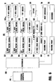
- an apparatus EG for engraving images is connected to a personal computer PC as shown in FIG. 6 .
- the apparatus EG comprises a base plate 10 having a given thickness and a width, on which a ⁇ -shaped driving stand 12 having a pair of legs 12a, 12a and an upper surface extending between the legs is rigidly mounted.
- An opening (not shown) is provided through a central portion of the leg 12a, and a pair of bearings 18, 18, each having an opening (not shown), are made independently.
- Both end portions of a spindle 14 is penetrated through the openings of the bearings 18, 18 and the openings of the legs 12a, 12a with a pair of coil springs 16, 16, each being located between a leg 12a and a bearing 18 respectively.
- the spindle 14 is mounted to extend horizontally and in parallel with the base plate 10 to form a vibration-preventing unit A.
- a second base plate 20a is integrally mounted on the top of each bearings 18, 18, a pair of driving and driven pulleys 36 and 34 are provided on a pair of blocks mounted on the second base plate 20a, a timing belt 38 is engaged on these pulleys 36 and 34, an X-axis feeder 30 is provided on the timing belt 38 and a ⁇ -shaped rail 28 extending parallel to the second base plate 20a and supported above it by legs extending downwardly at either end thereof, and an X-axis pulse motor driver 32 and an X-axis pulse motor 34a are connected to the X-axis feeder 30.
- a Y-axis driver C that is connected to the controller CR of the engraving apparatus EG comprises a Y-axis pulse motor driver 76 and a Y-axis pulse motor 78.
- a Z-axis driver D is provided on a head base, which is a top portion of the Y-axis driver C.
- the Z-axis driver D comprises a Z-axis head driver 54, a Z-axis head 56, a stylus 58 provided at a lower portion of the Z-axis head 56, and a minute ⁇ Y-axis driver E having a ⁇ Y-axis head driver 60 and a ⁇ Y-axis head 62 is connected to the stylus 58.
- a tilt driver F which is connected to the controller CR comprises a tilt pulse motor driver 64 and a tilt pulse motor 66 which is provided at a front portion of the Y-axis driver C so that when an adaptor 80 is tilted rearwards, an item to be engraved such as a passport P or an identification card ID can be easily placed on the adaptor 80.
- a vacuum pump 68 Mounted on the adaptor 80 and near the X-axis pulse motor 34a is a vacuum pump 68, an air hose 68a having a small diameter which is mounted to locate near the X-axis pulse motor 34a to work as a dust absorber 74 of the engraved cut dust or scrap.
- an adaptor 80 of one embodiment includes a rectangular table having a given thickness and width, and it can be put on the feeder 30.
- FIGS. 7 and 8 another end portion of the air hose 68a is put into the air opening 80c from a backside of the positioning rectangular groove 80a which is provided near an outer periphery of the adaptor 80, a depressed rectangular plane 80a' which is defined by the rectangular groove 80a is lowered slightly by about 0.1mm relative to the outer surface of the adaptor 80, and a pair of small air openings 80c, 80c are provided through the adaptor 80 to locate at the upper and lower grooves 80a, 80a, thus sucking out air from behind the adaptor 80 to hold the media such as an identification card ID on the depressed rectangular portion 80a'.
- FIGS. 9-11 An adaptor 90 of an alternative embodiment for engraving images on a passport P is shown in FIGS. 9-11 , in which the adaptor 90 has a holding table 92 and an inclined table 94 which is rigidly secured to one side edge portion of the holding table 92 and a lid plate 98 which is pivotally secured to the other side edge portion of the holding table 92.
- the holding table 92 has a given thickness and width, and a depressed rectangular plane 92a' which is defined by the rectangular groove 92a and is lowered slightly by about 0.1mm relative to the outer surface of the holding table, and a pair of small air openings 92c, 92c which are provided through the adaptor 90 to locate at the upper and lower grooves 92a, 92a, thus sucking air from behind the adaptor to hold the engraved passport P on the depressed rectangular plane 92a'.
- a pair of positioning ridges 96, 96 are provided on a top and a side portion of the holding table 92 respectively, and a rectangular window 98a is provided through the lid plate 98 in order to correspond with the depressed rectangular plane 92a'.
- a pair of clips 94a, 94a are provided at both corner portions of the inclined table 94, and a pair of grips 98c, 98c are mounted at both upper and lower portions of an outer edge portion of the lid plate 98 so that the engraved passport P may be correctly held between the holding table 92 and the lid plate 98 and smooth engraving can be easily carried out without causing vibration.
- the depressed rectangular plane 80a' which is defined by the rectangular groove 80a is lowered slightly by about 0.1 mm, and a pair of small air openings 80c, 80c are provided through the adaptor 80 to locate at the upper and lower grooves 80a, 80a so that media such as an identification card ID can be easily positioned on the depressed rectangular portion 80a' and held on the adaptor 80 by a negative pressure of air (or a vacuum).
- a suction pump, a pressure sensor, an electromagnetic valve and piping are connected to the air hose 68a in order to provide the negative pressure or vacuum required in use.
- the adaptor 90 for engraving images on a passport P comprises a depressed rectangular plane 90a' which is defined by the rectangular groove 90a and is lowered slightly by about 0.1mm, and a pair of small air openings 90c, 90c are provided through the adaptor 90 to locate at the upper and lower grooves 90a, 90a so that the engraved passport P can be disposed on the depressed rectangular portion 90a' to allow a correct and smooth engraving of the engraved passport P.
- the apparatus EG for engraving images on a passport, identification card, or the like is connected to the personal computer PC, an item for engraving such as a magnetic card is manually put onto the adaptor 80 or 90, which is mounted on the X-axis feeder 30, into which one or more images such as a picture of a face, a name, signature, identifying information, etc.
Landscapes
- Engineering & Computer Science (AREA)
- General Engineering & Computer Science (AREA)
- Mechanical Engineering (AREA)
- Credit Cards Or The Like (AREA)
- Manufacture Or Reproduction Of Printing Formes (AREA)
Description
- This invention relates to an apparatus for engraving images and its adaptor, and more particularly, an apparatus for engraving images such as photographs of faces, addresses, names, autographs or signatures, images for identifying one's identity, or the images from a digital camera, scanner or other information taken from a computer through a network onto identification cards such as passports, drivers' licenses, employee certificates or credit cards, and its adaptor.
- There have been proposed various engraving apparatuses (for example,
US Patent No. 5,232,321 , Japanese Patent publication Nos.115676/1989 24395/1993 201762/1988 - According to the conventional apparatus for engraving images on passports, driver's licenses, employee certificates or credit cards, a magnetic layer is coated on a surface of a plastic card or synthetic paper, and if necessary, a given thin colored layer is coated on a surface of the magnetic layer or synthetic paper, on which a given magnetic picture or image is engraved by a cutting head or a stylus.
- When making passports, driver's licenses, employee certificates, credit cards or other products of this type, photographs of faces, addresses, names, signatures, or other images containing information regarding an identity, etc. are engraved onto the products together with data such as the position of an employee, ID number etc. in order to increase the security of the engraved cards and to avoid their forgery.
- Engraving data sources can be roughly classified into image data and text data, which are displayed on a personal computer as independent data, and if necessary, they are combined in the personal computer.
- In accordance with the conventional engraving apparatus, independent character data and independent image data are inputted by an independent controller.
- In addition, it takes a long time and is expensive to develop software and data, and it is also necessary for a user to get used to the method of using the conventional engraving apparatus, thus increasing the burden for the user and making it difficult to transmit, edit and compress the data and causing much confusion and trouble.
- The biggest disadvantage of the conventional engraving apparatus is that when making a personal card, it is necessary to make the engraving apparatus file each set of data such as a face picture, address, name, or signature of one person independently and to then designate all of the files and to collect and integrate the data from the files.
- For the engraving data such as a face picture, address, name, signature and the images for engraving identifying information etc., there are plastic cards in addition to the magnetic or non-magnetic cards.
- There are many different kinds of the magnetic, non-magnetic cards or plastic cards such as standard sized, large-sized, passport size and other sized cards.
- Accordingly, it is necessary to make many different types of the expensive engraving apparatuses to handle the different cards.
- Further, it is likely that vibrations of an engraving head of the conventional engraving apparatus cause the engraving apparatus itself to oscillate thus causing incorrect engraving.
- A principal object of this invention at least in its preferred forms is to provide an apparatus for engraving images which comprises a personal computer, a controller, an X-axis pulse motor driver, a Y-axis pulse motor driver, an X-axis pulse motor, a tilt motor driver, a Z-axis head motor having a minute ΔY-axis driver, a stylus and a vacuum pump whereby photographs of faces, addresses, names, autographs, the images for engraving information identifying one's identity, the images from a digital camera, scanner or other information taken from a computer through a network can be automatically and correctly engraved on identification cards such as passports, drivers' licenses, employee certificates or credit cards.
- Another object of this invention at least in its preferred forms is to provide an apparatus for engraving images whereby a side-by-side comparison of the original image with an engraved image is not required for an operator so that erroneous inputting of information or wrong engraving of another person can be substantially avoided.
- Another object of this invention at least in its preferred forms is to provide an apparatus for engraving images comprising a vibration-preventing unit whereby smooth and correct engraving can be easily carried out without causing vibration.
- Another object of this invention is to provide an apparatus for engraving images, which is simple in construction so as to facilitate easy assembly, operation and maintenance.
- Another object of this invention at least in its preferred forms is to provide an apparatus for engraving images for a passport, identity card and the like whereby various different kinds of adaptors for holding the item to be engraved are prepared in advance in order to exchange the desired adaptors for different types of item without having to use different kinds of engraving apparatus for the different items.
- Another object of this invention at least in its preferred forms is to provide an adaptor for use in an apparatus for engraving images on identification cards, which comprises a rectangular table having a positioning groove and a ridge, which are respectively provided around and near a peripheral edge portion thereof, and a plurality of small air openings provided through the table at the given positions whereby an item to be engraved can be sucked towards and located on the table correctly.
- Still another object of this invention at least in its preferred forms is to provide an adaptor for use in an apparatus for engraving images which comprises a first rectangular table, a second rectangular table which is rigidly secured at a given obtuse angle to the first rectangular table, and a third rectangular table which is pivotally connected to the second rectangular table so that an item to be engraved can be sucked towards and located on the second rectangular table correctly.
- Viewed from one aspect, the invention provides an apparatus for engraving images which comprises means for supporting an item to be engraved and engraving means, characterised in that said means for supporting an item to be engraved comprises: a stand comprising a planar surface and a pair of legs rigidly mounted on a base support provided by a base plate having a given thickness and a width, wherein said each leg has an opening provided through a central portion thereof; a spindle penetrated through the openings of said legs supported by and extending between said legs parallel to said planar surface; and a pair of bearings mounted slidably on said spindle to reciprocate, wherein coil springs are provided on the spindle between each said leg and each said bearing to reduce the effect of vibration of the apparatus on a support surface for receiving the item to be engraved, said support surface being provided by a second base plate integrally mounted on the top portion of each bearing; said apparatus further comprising: a controller connected to a personal computer; a pair of driving and driven pulleys provided on a pair of blocks mounted on the second base plate; a timing belt engaged on said pulleys;
a Π-shaped rail mounted on the second base plate; an X-axis feeder provided on said timing belt and said Π-shaped rail; an X-axis pulse motor driver and an X-axis pulse motor connected to said X-axis feeder; a Y-axis driver connected to the controller; a Y-axis pulse motor driver connected to a Y-axis pulse motor; a Z-axis driver provided on a head base, which is a top portion of the Y-axis driver; a Z-axis driver including a Z-axis head driver and a Z-axis head; a stylus provided at a lower portion of the Z-axis head; a minute ΔY-axis driver having a Y-axis head driver and a ΔY-axis head connected to said stylus; and a tilt driver comprising a tilt pulse motor driver and a tilt pulse motor disposed at a front portion of the Y-axis driver in such a manner that when an adaptor is tilted rearwards, an item to be engraved such as a passport P or an identification card ID can be easily placed on the adaptor. - Preferred embodiments of the invention will now be described, by way of example only, and with reference to the accompanying drawings in which:
-
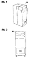
FIG. 1 is a perspective view of an embodiment of an apparatus according to the invention for engraving images or information identifying one's identity on a passport, or the like; -
FIG. 2 is a schematic front view of the apparatus for engraving images shown inFIG. 1 ; -
FIG. 3 is an enlarged element schematic perspective view of the apparatus for engraving images shown inFIG. 1 ; for engraving images according to the invention; -
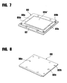
FIG. 7 is a schematic front perspective view of an embodiment of an adaptor according to the invention; -
FIG. 8 is a schematic perspective view of the adaptor shown inFIG. 7 , seen from the rear; -
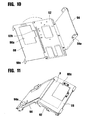
FIG. 9 is a schematic perspective view of an embodiment of an adaptor according to the invention, showing that a third rectangular table is pivotally opened with respect to the second rectangular table; -
FIG. 10 is a schematic perspective view of the adaptor shown inFIG. 9 , seen from the rear; and -
FIG. 11 is a schematic perspective view showing that in use a passport may be held between the second and third rectangular tables. - Referring to the accompanying drawings in which like numerals designate the like parts throughout the several views thereof, an apparatus EG for engraving images is connected to a personal computer PC as shown in
FIG. 6 . - As particularly shown in
FIGS. 2-6 , the apparatus EG comprises abase plate 10 having a given thickness and a width, on which a Π-shaped driving stand 12 having a pair oflegs - An opening (not shown) is provided through a central portion of the
leg 12a, and a pair ofbearings - Both end portions of a
spindle 14 is penetrated through the openings of thebearings legs coil springs leg 12a and abearing 18 respectively. - It should be appreciated that the
spindle 14 is mounted to extend horizontally and in parallel with thebase plate 10 to form a vibration-preventing unit A. - A
second base plate 20a is integrally mounted on the top of eachbearings pulleys second base plate 20a, atiming belt 38 is engaged on thesepulleys X-axis feeder 30 is provided on thetiming belt 38 and a Π-shaped rail 28 extending parallel to thesecond base plate 20a and supported above it by legs extending downwardly at either end thereof, and an X-axispulse motor driver 32 and anX-axis pulse motor 34a are connected to theX-axis feeder 30. - A Y-axis driver C that is connected to the controller CR of the engraving apparatus EG comprises a Y-axis
pulse motor driver 76 and a Y-axis pulse motor 78. - A Z-axis driver D is provided on a head base, which is a top portion of the Y-axis driver C.
- The Z-axis driver D comprises a Z-
axis head driver 54, a Z-axis head 56, astylus 58 provided at a lower portion of the Z-axis head 56, and a minute ΔY-axis driver E having a ΔY-axis head driver 60 and a ΔY-axis head 62 is connected to thestylus 58. - A tilt driver F which is connected to the controller CR comprises a tilt
pulse motor driver 64 and atilt pulse motor 66 which is provided at a front portion of the Y-axis driver C so that when anadaptor 80 is tilted rearwards, an item to be engraved such as a passport P or an identification card ID can be easily placed on theadaptor 80. - Mounted on the
adaptor 80 and near theX-axis pulse motor 34a is avacuum pump 68, anair hose 68a having a small diameter which is mounted to locate near theX-axis pulse motor 34a to work as a dust absorber 74 of the engraved cut dust or scrap. - As shown in
FIGS. 5-8 , anadaptor 80 of one embodiment includes a rectangular table having a given thickness and width, and it can be put on thefeeder 30. - As particularly shown in
FIGS. 7 and 8 , another end portion of theair hose 68a is put into the air opening 80c from a backside of the positioningrectangular groove 80a which is provided near an outer periphery of theadaptor 80, a depressedrectangular plane 80a' which is defined by therectangular groove 80a is lowered slightly by about 0.1mm relative to the outer surface of theadaptor 80, and a pair ofsmall air openings adaptor 80 to locate at the upper andlower grooves adaptor 80 to hold the media such as an identification card ID on the depressedrectangular portion 80a'. - An
adaptor 90 of an alternative embodiment for engraving images on a passport P is shown inFIGS. 9-11 , in which theadaptor 90 has a holding table 92 and an inclined table 94 which is rigidly secured to one side edge portion of the holding table 92 and alid plate 98 which is pivotally secured to the other side edge portion of the holding table 92. - More particularly, the holding table 92 has a given thickness and width, and a depressed
rectangular plane 92a' which is defined by therectangular groove 92a and is lowered slightly by about 0.1mm relative to the outer surface of the holding table, and a pair ofsmall air openings adaptor 90 to locate at the upper andlower grooves rectangular plane 92a'. - In addition, a pair of
positioning ridges rectangular window 98a is provided through thelid plate 98 in order to correspond with the depressedrectangular plane 92a'. - A pair of
clips grips lid plate 98 so that the engraved passport P may be correctly held between the holding table 92 and thelid plate 98 and smooth engraving can be easily carried out without causing vibration. - As explained in the foregoing paragraphs and as particularly shown in
FIGS. 7 and 8 , the depressedrectangular plane 80a' which is defined by therectangular groove 80a is lowered slightly by about 0.1 mm, and a pair ofsmall air openings adaptor 80 to locate at the upper andlower grooves rectangular portion 80a' and held on theadaptor 80 by a negative pressure of air (or a vacuum). - It should be appreciated that a suction pump, a pressure sensor, an electromagnetic valve and piping (not shown) are connected to the
air hose 68a in order to provide the negative pressure or vacuum required in use. - Like the example of the
adaptor 80, theadaptor 90 for engraving images on a passport P comprises a depressed rectangular plane 90a' which is defined by the rectangular groove 90a and is lowered slightly by about 0.1mm, and a pair of small air openings 90c, 90c are provided through theadaptor 90 to locate at the upper and lower grooves 90a, 90a so that the engraved passport P can be disposed on the depressed rectangular portion 90a' to allow a correct and smooth engraving of the engraved passport P. - In operation, the apparatus EG for engraving images on a passport, identification card, or the like is connected to the personal computer PC, an item for engraving such as a magnetic card is manually put onto the
adaptor X-axis feeder 30, into which one or more images such as a picture of a face, a name, signature, identifying information, etc. or other information data taken from a digital camera, scanner, or other computer through a network are transmitted by an image signal from the controller CR to cause thestylus 58 to be reciprocated rapidly right and left (in a direction of the X-axis), back and forth (in a direction of the Y-axis) and up and down (in a direction of the Z-axis) to engrave the desired images on the media such as a passport, identification card, or the like to a desired depth.
Claims (3)
- An apparatus for engraving images which comprises means for supporting an item to be engraved and engraving means, characterised in that said means for supporting an item to be engraved comprises: a stand (12) comprising a planar surface and a pair of legs (12A) rigidly mounted on a base support (10)provided by a base plate having a given thickness and a width, wherein said each leg has an opening provided through a central portion thereof; a spindle (14) penetrated through the openings of said legs supported by and extending between said legs parallel to said planar surface; and a pair of bearings (18,18) mounted slidably on said spindle to reciprocate, wherein coil springs (16) are provided on the spindle between each said leg and each said bearing to reduce the effect of vibration of the apparatus on a support surface (20A) for receiving the item to be engraved, said support surface being provided by a second base plate (20a) integrally mounted on the top portion of each bearing; said apparatus further comprising: a controller (CR) connected to a personal computer (PC);
a pair of driving and driven pulleys (34,36) provided on a pair of blocks mounted on the second base plate;
a timing belt (38) engaged on said pulleys;
a Π-shaped rail (28) mounted on the second base plate;
an X-axis feeder (30) provided on said timing belt and said Π-shaped rail;
an X-axis pulse motor driver (32) and an X-axis pulse motor (34a) connected to said X-axis feeder;
a Y-axis driver (C) connected to the controller;
a Y-axis pulse motor driver (76) connected to a Y-axis pulse motor (78);
a Z-axis driver (D) provided on a head base, which is a top portion of the Y-axis driver;
a Z-axis driver including a Z-axis head driver (54) and a Z-axis head (56) ;
a stylus (58) provided at a lower portion of the Z-axis head;
a minute ΔY-axis driver (E) having a Y-axis head driver and a ΔY-axis head connected to said stylus; and
a tilt driver (F) comprising a tilt pulse motor driver (64) and a tilt pulse motor (66) disposed at a front portion of the Y-axis driver in such a manner that when an adaptor (80;90) is tilted rearwards, an item to be engraved such as a passport P or an identification card ID can be easily placed on the adaptor. - An apparatus as claimed in claim 1, further comprising an adaptor (80;90), which comprises a rectangular table having a given thickness and width which is put on the feeder in use, said rectangular table having a positioning rectangular groove (80a;92a) provided near an outer periphery thereof, said rectangular groove defining a depressed rectangular plane (80a';92a') which is lowered slightly by about 0.1mm with respect to the outer periphery of the rectangular table, a pair of small air openings (80c;92c) provided through the adaptor to locate at the upper and lower ends of the rectangular groove, an air hose being disposed behind said table, one end portion of said air hose being put into the air opening from the rear and another end being connected to a vacuum pump in order to hold the item to be engraved to the adaptor through a negative pressure of air.
- An apparatus as claimed in claim 2, said adaptor further comprising an inclined table (94) which is rigidly secured to one side edge portion of the rectangular table (92) and a lid plate (98) which is pivotally secured to the other side edge portion of the rectangular table, a pair of positioning ridges (96) being provided on a top portion and a side portion of the said rectangular table respectively, a rectangular window (98a) being provided through the lid plate in order to correspond with the depressed rectangular plane (92a'), a pair of clips (94a) being provided at both corner portions of the inclined table and a pair of grips (98c) being mounted at both upper and lower portions of an outer edge portion of the lid plate so that the item to be engraved may be correctly held between the holding table and the lid plate and smooth engraving can be.easily carried out without causing vibration.
Priority Applications (1)
| Application Number | Priority Date | Filing Date | Title |
|---|---|---|---|
| EP05018221A EP1616717B1 (en) | 2000-09-12 | 2001-09-12 | Adaptor for the use in an apparatus for engraving images and corresponding apparatus |
Applications Claiming Priority (2)
| Application Number | Priority Date | Filing Date | Title |
|---|---|---|---|
| JP2000318605A JP4498580B2 (en) | 2000-09-12 | 2000-09-12 | Image engraving equipment |
| JP2000318605 | 2000-09-12 |
Related Child Applications (1)
| Application Number | Title | Priority Date | Filing Date |
|---|---|---|---|
| EP05018221A Division EP1616717B1 (en) | 2000-09-12 | 2001-09-12 | Adaptor for the use in an apparatus for engraving images and corresponding apparatus |
Publications (4)
| Publication Number | Publication Date |
|---|---|
| EP1195268A2 EP1195268A2 (en) | 2002-04-10 |
| EP1195268A3 EP1195268A3 (en) | 2002-07-31 |
| EP1195268B1 true EP1195268B1 (en) | 2008-07-30 |
| EP1195268B9 EP1195268B9 (en) | 2009-07-08 |
Family
ID=18797201
Family Applications (2)
| Application Number | Title | Priority Date | Filing Date |
|---|---|---|---|
| EP01307784A Expired - Lifetime EP1195268B9 (en) | 2000-09-12 | 2001-09-12 | An apparatus for engraving images and its adaptor for holding the piece to be engraved |
| EP05018221A Expired - Lifetime EP1616717B1 (en) | 2000-09-12 | 2001-09-12 | Adaptor for the use in an apparatus for engraving images and corresponding apparatus |
Family Applications After (1)
| Application Number | Title | Priority Date | Filing Date |
|---|---|---|---|
| EP05018221A Expired - Lifetime EP1616717B1 (en) | 2000-09-12 | 2001-09-12 | Adaptor for the use in an apparatus for engraving images and corresponding apparatus |
Country Status (8)
| Country | Link |
|---|---|
| US (2) | US20020030318A1 (en) |
| EP (2) | EP1195268B9 (en) |
| JP (1) | JP4498580B2 (en) |
| KR (2) | KR20020021063A (en) |
| CN (1) | CN100491138C (en) |
| CA (1) | CA2357228C (en) |
| DE (2) | DE60138317D1 (en) |
| TW (1) | TWI276553B (en) |
Families Citing this family (13)
| Publication number | Priority date | Publication date | Assignee | Title |
|---|---|---|---|---|
| US20080057295A1 (en) * | 2006-09-01 | 2008-03-06 | Fina Technology, Inc. | Engravable board |
| CN102290573B (en) | 2007-03-30 | 2015-07-08 | 索尼株式会社 | Cathode active material, cathode and nonaqueous electrolyte battery |
| JP2009096129A (en) * | 2007-10-18 | 2009-05-07 | Semco Corp | Image engraving apparatus |
| US8424216B2 (en) * | 2009-11-09 | 2013-04-23 | The Hillman Group, Inc. | Dual-side engraving system |
| CN102431366B (en) * | 2011-09-15 | 2015-03-11 | 深圳大宇精雕科技有限公司 | Fine-engraving machine capable of loading and unloading automatically |
| KR101297899B1 (en) * | 2013-04-04 | 2013-08-22 | 최신자 | Hologram stamping device capable of automatic adjustment of stamping position |
| JP6582282B2 (en) * | 2014-10-30 | 2019-10-02 | 株式会社ワールドベンチャー | Image engraving equipment |
| WO2017025994A1 (en) * | 2015-08-11 | 2017-02-16 | セムコ株式会社 | Structure for securing medium to be engraved |
| CN107009794B (en) * | 2017-05-16 | 2018-09-18 | 安庆市宏大涛业精啄数控科技有限公司 | A kind of rotatable engraving machine auxiliary fagging |
| CN109955632B (en) * | 2019-05-06 | 2024-03-08 | 北海绩迅科技股份有限公司 | Engraving capacity-expanding equipment for ink box |
| CN110245612A (en) * | 2019-06-14 | 2019-09-17 | 百度在线网络技术(北京)有限公司 | The detection method and device of facial image |
| CN110356156B (en) * | 2019-07-08 | 2020-11-10 | 浙江易正智能科技有限公司 | Translation formula license plate printing device |
| US20220048314A1 (en) * | 2020-08-13 | 2022-02-17 | The Hillman Group, Inc. | Engraving machine for engraving offboard and onboard items |
Family Cites Families (27)
| Publication number | Priority date | Publication date | Assignee | Title |
|---|---|---|---|---|
| US2809005A (en) * | 1954-10-06 | 1957-10-08 | Kenneth E Goode | Shock and vibration mount having non-rotational features |
| US3803979A (en) * | 1972-08-31 | 1974-04-16 | J Young | Engraving apparatus |
| JPS4966223A (en) * | 1972-10-31 | 1974-06-27 | ||
| US3927599A (en) * | 1972-11-24 | 1975-12-23 | Raymond Jean Louis | Universal engraving machine |
| JPS51138982A (en) * | 1975-05-28 | 1976-11-30 | Tokyo Juki Ind Co Ltd | A device for engraving the image of picture |
| US4385360A (en) * | 1980-08-04 | 1983-05-24 | Micro-Power Computer Systems | Computer-controlled reproduction device |
| JPS5994894U (en) * | 1982-12-17 | 1984-06-27 | 古河電気工業株式会社 | Shavings suction pipe for image engraving |
| FR2596313B1 (en) * | 1986-03-28 | 1989-06-30 | Gravograph | SYSTEM FOR FIXING BY SUCTION OF A WORKING PLATE, PARTICULARLY IN ENGRAVING |
| IT1201847B (en) * | 1986-09-23 | 1989-02-02 | G L C Di Ceriotti Gino | PROCEDURE AND MACHINE FOR ENGRAVING THE LARGER SURFACES OF CRYSTAL SLABS WITH GROOVES, MEDIUM DEEP, EVEN BLANK, ACCORDING TO DRAWINGS, MIXTURES, REPETITIVES AND THEIR COMBINATIONS, AND CRYSTAL SLABS OBTAINED WITH SUCH PROCEDURE AND MACHINE |
| FR2612329B1 (en) * | 1987-03-09 | 1989-05-19 | Vibrachoc Sa | SUSPENSION DEVICE AUTHORIZING AN OBJECT TO MOVE IN A PLANE |
| FR2633748B1 (en) * | 1988-06-30 | 1992-03-06 | Schlumberger Ind Sa | WRITING TOOL IDENTIFICATION METHOD AND DEVICE |
| US4989823A (en) * | 1989-04-28 | 1991-02-05 | Leonard Studio Equipment, Inc. | Shock and vibration isolator |
| US5116174A (en) * | 1989-11-13 | 1992-05-26 | Kenneth Fried | Method and apparatus for manufacturing jewelry, and an article of jewelry made thereby |
| FR2664534B1 (en) * | 1990-07-13 | 1993-09-24 | De Boisgrollier Dominique | AUTOMATIC OBJECT ENGRAVING MACHINE. |
| JPH04166398A (en) * | 1990-10-30 | 1992-06-12 | Nec Home Electron Ltd | Cutter driver of card carving machine |
| JP2857635B2 (en) * | 1991-07-24 | 1999-02-17 | 株式会社セブンファースト | Image engraving equipment |
| US5512005A (en) * | 1992-08-28 | 1996-04-30 | Michael P. Short | Process and apparatus for automatically engraving stone memorial markers |
| US5504301A (en) * | 1994-03-21 | 1996-04-02 | Laser Cut Images International, Inc. | Apparatus and method for laser engraving thin sheet-like materials |
| US5569003A (en) * | 1994-05-13 | 1996-10-29 | Quick-Tag, Inc. | Automated engraving apparatus and method |
| US5493965A (en) * | 1994-06-16 | 1996-02-27 | Lizarazu; Pio E. | Impact engraving machine |
| JPH0837225A (en) * | 1994-07-26 | 1996-02-06 | Hitachi Ltd | Jig for manufacturing semiconductor and testing equipment using that jig |
| FR2723333B1 (en) * | 1994-08-08 | 1996-09-20 | Technifor Sa | MARKING DEVICE FOR PRODUCING TWO-DIMENSIONAL IDENTIFICATION SIGNS ON THE SURFACE OF ANY OBJECT |
| FR2729892B1 (en) * | 1995-01-31 | 1997-07-18 | Nicolas Michel | DEVICE FOR PRESSURE TABLES OF ENGRAVING MACHINES |
| JPH0929923A (en) * | 1995-07-18 | 1997-02-04 | Dainippon Screen Mfg Co Ltd | Lubricant coating device of gravure carving machine |
| JPH09150599A (en) * | 1995-11-28 | 1997-06-10 | Roland D G Kk | Material discharge chute device and stamping machine with the device |
| US6186711B1 (en) * | 1998-04-03 | 2001-02-13 | Axxess Technologies, Inc. | Engraving system |
| US6046563A (en) * | 1998-08-19 | 2000-04-04 | Moreyra; Manuel R. | Haptic device |
-
2000
- 2000-09-12 JP JP2000318605A patent/JP4498580B2/en not_active Expired - Lifetime
-
2001
- 2001-09-11 TW TW090122470A patent/TWI276553B/en not_active IP Right Cessation
- 2001-09-11 CN CN01138577.4A patent/CN100491138C/en not_active Expired - Fee Related
- 2001-09-12 EP EP01307784A patent/EP1195268B9/en not_active Expired - Lifetime
- 2001-09-12 US US09/950,078 patent/US20020030318A1/en not_active Abandoned
- 2001-09-12 EP EP05018221A patent/EP1616717B1/en not_active Expired - Lifetime
- 2001-09-12 CA CA2357228A patent/CA2357228C/en not_active Expired - Lifetime
- 2001-09-12 KR KR1020010056172A patent/KR20020021063A/en active Search and Examination
- 2001-09-12 DE DE60138317T patent/DE60138317D1/en not_active Expired - Lifetime
- 2001-09-12 DE DE60135075T patent/DE60135075D1/en not_active Expired - Lifetime
-
2004
- 2004-07-28 US US10/900,330 patent/US6976315B2/en not_active Expired - Lifetime
-
2007
- 2007-08-21 KR KR1020070084097A patent/KR20070088437A/en not_active Application Discontinuation
Also Published As
| Publication number | Publication date |
|---|---|
| KR20020021063A (en) | 2002-03-18 |
| DE60135075D1 (en) | 2008-09-11 |
| DE60138317D1 (en) | 2009-05-20 |
| US20020030318A1 (en) | 2002-03-14 |
| US6976315B2 (en) | 2005-12-20 |
| EP1616717A2 (en) | 2006-01-18 |
| JP4498580B2 (en) | 2010-07-07 |
| EP1616717A3 (en) | 2007-09-05 |
| CA2357228A1 (en) | 2002-03-12 |
| CN1367091A (en) | 2002-09-04 |
| EP1195268A2 (en) | 2002-04-10 |
| CN100491138C (en) | 2009-05-27 |
| EP1195268A3 (en) | 2002-07-31 |
| KR20070088437A (en) | 2007-08-29 |
| US20050005460A1 (en) | 2005-01-13 |
| JP2002086993A (en) | 2002-03-26 |
| CA2357228C (en) | 2010-08-17 |
| EP1195268B9 (en) | 2009-07-08 |
| EP1616717B1 (en) | 2009-04-08 |
| TWI276553B (en) | 2007-03-21 |
Similar Documents
| Publication | Publication Date | Title |
|---|---|---|
| EP1195268B1 (en) | An apparatus for engraving images and its adaptor for holding the piece to be engraved | |
| US20080134853A2 (en) | Automatic pattern making device | |
| GB2362604A (en) | Book cover with an alignment feature | |
| US20050268508A1 (en) | Document display and retention device | |
| US20030118689A1 (en) | Embossing system | |
| CN107980025A (en) | Imprinter and the pressing plate holder for imprinter | |
| JP4251929B2 (en) | Combination of document reader and document table | |
| JP4229771B2 (en) | Postcard preparation machine | |
| JP3237408U (en) | Business card | |
| CN220254550U (en) | High appearance location auxiliary device that beats | |
| CN212373027U (en) | Book side band three-dimensional image-text hardcover book | |
| US7568415B2 (en) | Device for cutting mat and liner for double matted framed artwork | |
| JP2596789Y2 (en) | Trimming tools | |
| JP2009137169A (en) | Security sheet | |
| US4975731A (en) | Apparatus for producing a form having driver's license information thereon | |
| US20040221750A1 (en) | Embossing guide | |
| JP3021211U (en) | Card cut gauge | |
| JPH01142551A (en) | Sheet for photograph or the like and apparatus for producing said sheet | |
| JPH1159031A (en) | Paper for information input cutting die |
Legal Events
| Date | Code | Title | Description |
|---|---|---|---|
| PUAI | Public reference made under article 153(3) epc to a published international application that has entered the european phase |
Free format text: ORIGINAL CODE: 0009012 |
|
| AK | Designated contracting states |
Kind code of ref document: A2 Designated state(s): AT BE CH CY DE DK ES FI FR GB GR IE IT LI LU MC NL PT SE TR |
|
| AX | Request for extension of the european patent |
Free format text: AL;LT;LV;MK;RO;SI |
|
| PUAL | Search report despatched |
Free format text: ORIGINAL CODE: 0009013 |
|
| AK | Designated contracting states |
Kind code of ref document: A3 Designated state(s): AT BE CH CY DE DK ES FI FR GB GR IE IT LI LU MC NL PT SE TR |
|
| AX | Request for extension of the european patent |
Free format text: AL;LT;LV;MK;RO;SI |
|
| 17P | Request for examination filed |
Effective date: 20030131 |
|
| AKX | Designation fees paid |
Designated state(s): DE FR GB IT |
|
| 17Q | First examination report despatched |
Effective date: 20050125 |
|
| GRAP | Despatch of communication of intention to grant a patent |
Free format text: ORIGINAL CODE: EPIDOSNIGR1 |
|
| RAP1 | Party data changed (applicant data changed or rights of an application transferred) |
Owner name: SEMCO CORPORATION |
|
| GRAS | Grant fee paid |
Free format text: ORIGINAL CODE: EPIDOSNIGR3 |
|
| GRAA | (expected) grant |
Free format text: ORIGINAL CODE: 0009210 |
|
| AK | Designated contracting states |
Kind code of ref document: B1 Designated state(s): DE FR GB IT |
|
| REG | Reference to a national code |
Ref country code: GB Ref legal event code: FG4D |
|
| REF | Corresponds to: |
Ref document number: 60135075 Country of ref document: DE Date of ref document: 20080911 Kind code of ref document: P |
|
| PLBE | No opposition filed within time limit |
Free format text: ORIGINAL CODE: 0009261 |
|
| STAA | Information on the status of an ep patent application or granted ep patent |
Free format text: STATUS: NO OPPOSITION FILED WITHIN TIME LIMIT |
|
| 26N | No opposition filed |
Effective date: 20090506 |
|
| REG | Reference to a national code |
Ref country code: FR Ref legal event code: PLFP Year of fee payment: 16 |
|
| PGFP | Annual fee paid to national office [announced via postgrant information from national office to epo] |
Ref country code: GB Payment date: 20160919 Year of fee payment: 16 |
|
| PGFP | Annual fee paid to national office [announced via postgrant information from national office to epo] |
Ref country code: FR Payment date: 20160921 Year of fee payment: 16 |
|
| PGFP | Annual fee paid to national office [announced via postgrant information from national office to epo] |
Ref country code: IT Payment date: 20160927 Year of fee payment: 16 |
|
| GBPC | Gb: european patent ceased through non-payment of renewal fee |
Effective date: 20170912 |
|
| REG | Reference to a national code |
Ref country code: FR Ref legal event code: ST Effective date: 20180531 |
|
| PG25 | Lapsed in a contracting state [announced via postgrant information from national office to epo] |
Ref country code: GB Free format text: LAPSE BECAUSE OF NON-PAYMENT OF DUE FEES Effective date: 20170912 |
|
| PG25 | Lapsed in a contracting state [announced via postgrant information from national office to epo] |
Ref country code: IT Free format text: LAPSE BECAUSE OF NON-PAYMENT OF DUE FEES Effective date: 20170912 Ref country code: FR Free format text: LAPSE BECAUSE OF NON-PAYMENT OF DUE FEES Effective date: 20171002 |
|
| PGFP | Annual fee paid to national office [announced via postgrant information from national office to epo] |
Ref country code: DE Payment date: 20190919 Year of fee payment: 19 |
|
| REG | Reference to a national code |
Ref country code: DE Ref legal event code: R082 Ref document number: 60135075 Country of ref document: DE Representative=s name: DEHNS, DE Ref country code: DE Ref legal event code: R081 Ref document number: 60135075 Country of ref document: DE Owner name: SEMCO INTERNATIONAL LIMITED, HK Free format text: FORMER OWNER: SEMCO CORPORATION, TOKYO, JP |
|
| REG | Reference to a national code |
Ref country code: DE Ref legal event code: R119 Ref document number: 60135075 Country of ref document: DE |
|
| PG25 | Lapsed in a contracting state [announced via postgrant information from national office to epo] |
Ref country code: DE Free format text: LAPSE BECAUSE OF NON-PAYMENT OF DUE FEES Effective date: 20210401 |