EP1194087B1 - Implant intersomatique anatomique - Google Patents
Implant intersomatique anatomique Download PDFInfo
- Publication number
- EP1194087B1 EP1194087B1 EP00949674A EP00949674A EP1194087B1 EP 1194087 B1 EP1194087 B1 EP 1194087B1 EP 00949674 A EP00949674 A EP 00949674A EP 00949674 A EP00949674 A EP 00949674A EP 1194087 B1 EP1194087 B1 EP 1194087B1
- Authority
- EP
- European Patent Office
- Prior art keywords
- sagittal
- walls
- frontal
- implant
- cage
- Prior art date
- Legal status (The legal status is an assumption and is not a legal conclusion. Google has not performed a legal analysis and makes no representation as to the accuracy of the status listed.)
- Expired - Lifetime
Links
- 239000007943 implant Substances 0.000 title claims abstract description 31
- 230000000295 complement effect Effects 0.000 claims description 8
- 210000000988 bone and bone Anatomy 0.000 claims description 6
- 239000000945 filler Substances 0.000 claims 1
- 239000003550 marker Substances 0.000 claims 1
- 210000003484 anatomy Anatomy 0.000 description 3
- 230000004927 fusion Effects 0.000 description 3
- 208000008558 Osteophyte Diseases 0.000 description 1
- 238000004880 explosion Methods 0.000 description 1
- 238000003780 insertion Methods 0.000 description 1
- 230000037431 insertion Effects 0.000 description 1
- 238000012986 modification Methods 0.000 description 1
- 230000004048 modification Effects 0.000 description 1
- 210000002445 nipple Anatomy 0.000 description 1
- 238000011084 recovery Methods 0.000 description 1
- 230000003068 static effect Effects 0.000 description 1
Images


Classifications
-
- A—HUMAN NECESSITIES
- A61—MEDICAL OR VETERINARY SCIENCE; HYGIENE
- A61F—FILTERS IMPLANTABLE INTO BLOOD VESSELS; PROSTHESES; DEVICES PROVIDING PATENCY TO, OR PREVENTING COLLAPSING OF, TUBULAR STRUCTURES OF THE BODY, e.g. STENTS; ORTHOPAEDIC, NURSING OR CONTRACEPTIVE DEVICES; FOMENTATION; TREATMENT OR PROTECTION OF EYES OR EARS; BANDAGES, DRESSINGS OR ABSORBENT PADS; FIRST-AID KITS
- A61F2/00—Filters implantable into blood vessels; Prostheses, i.e. artificial substitutes or replacements for parts of the body; Appliances for connecting them with the body; Devices providing patency to, or preventing collapsing of, tubular structures of the body, e.g. stents
- A61F2/02—Prostheses implantable into the body
- A61F2/30—Joints
- A61F2/46—Special tools for implanting artificial joints
- A61F2/4603—Special tools for implanting artificial joints for insertion or extraction of endoprosthetic joints or of accessories thereof
- A61F2/4611—Special tools for implanting artificial joints for insertion or extraction of endoprosthetic joints or of accessories thereof of spinal prostheses
-
- A—HUMAN NECESSITIES
- A61—MEDICAL OR VETERINARY SCIENCE; HYGIENE
- A61F—FILTERS IMPLANTABLE INTO BLOOD VESSELS; PROSTHESES; DEVICES PROVIDING PATENCY TO, OR PREVENTING COLLAPSING OF, TUBULAR STRUCTURES OF THE BODY, e.g. STENTS; ORTHOPAEDIC, NURSING OR CONTRACEPTIVE DEVICES; FOMENTATION; TREATMENT OR PROTECTION OF EYES OR EARS; BANDAGES, DRESSINGS OR ABSORBENT PADS; FIRST-AID KITS
- A61F2/00—Filters implantable into blood vessels; Prostheses, i.e. artificial substitutes or replacements for parts of the body; Appliances for connecting them with the body; Devices providing patency to, or preventing collapsing of, tubular structures of the body, e.g. stents
- A61F2/02—Prostheses implantable into the body
- A61F2/30—Joints
- A61F2/44—Joints for the spine, e.g. vertebrae, spinal discs
- A61F2/4455—Joints for the spine, e.g. vertebrae, spinal discs for the fusion of spinal bodies, e.g. intervertebral fusion of adjacent spinal bodies, e.g. fusion cages
- A61F2/447—Joints for the spine, e.g. vertebrae, spinal discs for the fusion of spinal bodies, e.g. intervertebral fusion of adjacent spinal bodies, e.g. fusion cages substantially parallelepipedal, e.g. having a rectangular or trapezoidal cross-section
-
- A—HUMAN NECESSITIES
- A61—MEDICAL OR VETERINARY SCIENCE; HYGIENE
- A61F—FILTERS IMPLANTABLE INTO BLOOD VESSELS; PROSTHESES; DEVICES PROVIDING PATENCY TO, OR PREVENTING COLLAPSING OF, TUBULAR STRUCTURES OF THE BODY, e.g. STENTS; ORTHOPAEDIC, NURSING OR CONTRACEPTIVE DEVICES; FOMENTATION; TREATMENT OR PROTECTION OF EYES OR EARS; BANDAGES, DRESSINGS OR ABSORBENT PADS; FIRST-AID KITS
- A61F2/00—Filters implantable into blood vessels; Prostheses, i.e. artificial substitutes or replacements for parts of the body; Appliances for connecting them with the body; Devices providing patency to, or preventing collapsing of, tubular structures of the body, e.g. stents
- A61F2/02—Prostheses implantable into the body
- A61F2/30—Joints
- A61F2/44—Joints for the spine, e.g. vertebrae, spinal discs
- A61F2/442—Intervertebral or spinal discs, e.g. resilient
-
- A—HUMAN NECESSITIES
- A61—MEDICAL OR VETERINARY SCIENCE; HYGIENE
- A61F—FILTERS IMPLANTABLE INTO BLOOD VESSELS; PROSTHESES; DEVICES PROVIDING PATENCY TO, OR PREVENTING COLLAPSING OF, TUBULAR STRUCTURES OF THE BODY, e.g. STENTS; ORTHOPAEDIC, NURSING OR CONTRACEPTIVE DEVICES; FOMENTATION; TREATMENT OR PROTECTION OF EYES OR EARS; BANDAGES, DRESSINGS OR ABSORBENT PADS; FIRST-AID KITS
- A61F2/00—Filters implantable into blood vessels; Prostheses, i.e. artificial substitutes or replacements for parts of the body; Appliances for connecting them with the body; Devices providing patency to, or preventing collapsing of, tubular structures of the body, e.g. stents
- A61F2/02—Prostheses implantable into the body
- A61F2/28—Bones
- A61F2002/2835—Bone graft implants for filling a bony defect or an endoprosthesis cavity, e.g. by synthetic material or biological material
-
- A—HUMAN NECESSITIES
- A61—MEDICAL OR VETERINARY SCIENCE; HYGIENE
- A61F—FILTERS IMPLANTABLE INTO BLOOD VESSELS; PROSTHESES; DEVICES PROVIDING PATENCY TO, OR PREVENTING COLLAPSING OF, TUBULAR STRUCTURES OF THE BODY, e.g. STENTS; ORTHOPAEDIC, NURSING OR CONTRACEPTIVE DEVICES; FOMENTATION; TREATMENT OR PROTECTION OF EYES OR EARS; BANDAGES, DRESSINGS OR ABSORBENT PADS; FIRST-AID KITS
- A61F2/00—Filters implantable into blood vessels; Prostheses, i.e. artificial substitutes or replacements for parts of the body; Appliances for connecting them with the body; Devices providing patency to, or preventing collapsing of, tubular structures of the body, e.g. stents
- A61F2/02—Prostheses implantable into the body
- A61F2/30—Joints
- A61F2002/30001—Additional features of subject-matter classified in A61F2/28, A61F2/30 and subgroups thereof
- A61F2002/30003—Material related properties of the prosthesis or of a coating on the prosthesis
- A61F2002/3006—Properties of materials and coating materials
- A61F2002/3008—Properties of materials and coating materials radio-opaque, e.g. radio-opaque markers
-
- A—HUMAN NECESSITIES
- A61—MEDICAL OR VETERINARY SCIENCE; HYGIENE
- A61F—FILTERS IMPLANTABLE INTO BLOOD VESSELS; PROSTHESES; DEVICES PROVIDING PATENCY TO, OR PREVENTING COLLAPSING OF, TUBULAR STRUCTURES OF THE BODY, e.g. STENTS; ORTHOPAEDIC, NURSING OR CONTRACEPTIVE DEVICES; FOMENTATION; TREATMENT OR PROTECTION OF EYES OR EARS; BANDAGES, DRESSINGS OR ABSORBENT PADS; FIRST-AID KITS
- A61F2/00—Filters implantable into blood vessels; Prostheses, i.e. artificial substitutes or replacements for parts of the body; Appliances for connecting them with the body; Devices providing patency to, or preventing collapsing of, tubular structures of the body, e.g. stents
- A61F2/02—Prostheses implantable into the body
- A61F2/30—Joints
- A61F2002/30001—Additional features of subject-matter classified in A61F2/28, A61F2/30 and subgroups thereof
- A61F2002/30108—Shapes
- A61F2002/30199—Three-dimensional shapes
- A61F2002/30261—Three-dimensional shapes parallelepipedal
-
- A—HUMAN NECESSITIES
- A61—MEDICAL OR VETERINARY SCIENCE; HYGIENE
- A61F—FILTERS IMPLANTABLE INTO BLOOD VESSELS; PROSTHESES; DEVICES PROVIDING PATENCY TO, OR PREVENTING COLLAPSING OF, TUBULAR STRUCTURES OF THE BODY, e.g. STENTS; ORTHOPAEDIC, NURSING OR CONTRACEPTIVE DEVICES; FOMENTATION; TREATMENT OR PROTECTION OF EYES OR EARS; BANDAGES, DRESSINGS OR ABSORBENT PADS; FIRST-AID KITS
- A61F2/00—Filters implantable into blood vessels; Prostheses, i.e. artificial substitutes or replacements for parts of the body; Appliances for connecting them with the body; Devices providing patency to, or preventing collapsing of, tubular structures of the body, e.g. stents
- A61F2/02—Prostheses implantable into the body
- A61F2/30—Joints
- A61F2002/30001—Additional features of subject-matter classified in A61F2/28, A61F2/30 and subgroups thereof
- A61F2002/30108—Shapes
- A61F2002/30199—Three-dimensional shapes
- A61F2002/30261—Three-dimensional shapes parallelepipedal
- A61F2002/30266—Three-dimensional shapes parallelepipedal wedge-shaped parallelepipeds
-
- A—HUMAN NECESSITIES
- A61—MEDICAL OR VETERINARY SCIENCE; HYGIENE
- A61F—FILTERS IMPLANTABLE INTO BLOOD VESSELS; PROSTHESES; DEVICES PROVIDING PATENCY TO, OR PREVENTING COLLAPSING OF, TUBULAR STRUCTURES OF THE BODY, e.g. STENTS; ORTHOPAEDIC, NURSING OR CONTRACEPTIVE DEVICES; FOMENTATION; TREATMENT OR PROTECTION OF EYES OR EARS; BANDAGES, DRESSINGS OR ABSORBENT PADS; FIRST-AID KITS
- A61F2/00—Filters implantable into blood vessels; Prostheses, i.e. artificial substitutes or replacements for parts of the body; Appliances for connecting them with the body; Devices providing patency to, or preventing collapsing of, tubular structures of the body, e.g. stents
- A61F2/02—Prostheses implantable into the body
- A61F2/30—Joints
- A61F2002/30001—Additional features of subject-matter classified in A61F2/28, A61F2/30 and subgroups thereof
- A61F2002/30316—The prosthesis having different structural features at different locations within the same prosthesis; Connections between prosthetic parts; Special structural features of bone or joint prostheses not otherwise provided for
- A61F2002/30317—The prosthesis having different structural features at different locations within the same prosthesis
- A61F2002/30324—The prosthesis having different structural features at different locations within the same prosthesis differing in thickness
-
- A—HUMAN NECESSITIES
- A61—MEDICAL OR VETERINARY SCIENCE; HYGIENE
- A61F—FILTERS IMPLANTABLE INTO BLOOD VESSELS; PROSTHESES; DEVICES PROVIDING PATENCY TO, OR PREVENTING COLLAPSING OF, TUBULAR STRUCTURES OF THE BODY, e.g. STENTS; ORTHOPAEDIC, NURSING OR CONTRACEPTIVE DEVICES; FOMENTATION; TREATMENT OR PROTECTION OF EYES OR EARS; BANDAGES, DRESSINGS OR ABSORBENT PADS; FIRST-AID KITS
- A61F2/00—Filters implantable into blood vessels; Prostheses, i.e. artificial substitutes or replacements for parts of the body; Appliances for connecting them with the body; Devices providing patency to, or preventing collapsing of, tubular structures of the body, e.g. stents
- A61F2/02—Prostheses implantable into the body
- A61F2/30—Joints
- A61F2002/30001—Additional features of subject-matter classified in A61F2/28, A61F2/30 and subgroups thereof
- A61F2002/30316—The prosthesis having different structural features at different locations within the same prosthesis; Connections between prosthetic parts; Special structural features of bone or joint prostheses not otherwise provided for
- A61F2002/30535—Special structural features of bone or joint prostheses not otherwise provided for
- A61F2002/30593—Special structural features of bone or joint prostheses not otherwise provided for hollow
-
- A—HUMAN NECESSITIES
- A61—MEDICAL OR VETERINARY SCIENCE; HYGIENE
- A61F—FILTERS IMPLANTABLE INTO BLOOD VESSELS; PROSTHESES; DEVICES PROVIDING PATENCY TO, OR PREVENTING COLLAPSING OF, TUBULAR STRUCTURES OF THE BODY, e.g. STENTS; ORTHOPAEDIC, NURSING OR CONTRACEPTIVE DEVICES; FOMENTATION; TREATMENT OR PROTECTION OF EYES OR EARS; BANDAGES, DRESSINGS OR ABSORBENT PADS; FIRST-AID KITS
- A61F2/00—Filters implantable into blood vessels; Prostheses, i.e. artificial substitutes or replacements for parts of the body; Appliances for connecting them with the body; Devices providing patency to, or preventing collapsing of, tubular structures of the body, e.g. stents
- A61F2/02—Prostheses implantable into the body
- A61F2/30—Joints
- A61F2/30767—Special external or bone-contacting surface, e.g. coating for improving bone ingrowth
- A61F2/30771—Special external or bone-contacting surface, e.g. coating for improving bone ingrowth applied in original prostheses, e.g. holes or grooves
- A61F2002/30772—Apertures or holes, e.g. of circular cross section
- A61F2002/30777—Oblong apertures
-
- A—HUMAN NECESSITIES
- A61—MEDICAL OR VETERINARY SCIENCE; HYGIENE
- A61F—FILTERS IMPLANTABLE INTO BLOOD VESSELS; PROSTHESES; DEVICES PROVIDING PATENCY TO, OR PREVENTING COLLAPSING OF, TUBULAR STRUCTURES OF THE BODY, e.g. STENTS; ORTHOPAEDIC, NURSING OR CONTRACEPTIVE DEVICES; FOMENTATION; TREATMENT OR PROTECTION OF EYES OR EARS; BANDAGES, DRESSINGS OR ABSORBENT PADS; FIRST-AID KITS
- A61F2/00—Filters implantable into blood vessels; Prostheses, i.e. artificial substitutes or replacements for parts of the body; Appliances for connecting them with the body; Devices providing patency to, or preventing collapsing of, tubular structures of the body, e.g. stents
- A61F2/02—Prostheses implantable into the body
- A61F2/30—Joints
- A61F2/30767—Special external or bone-contacting surface, e.g. coating for improving bone ingrowth
- A61F2/30771—Special external or bone-contacting surface, e.g. coating for improving bone ingrowth applied in original prostheses, e.g. holes or grooves
- A61F2002/3082—Grooves
- A61F2002/30827—Plurality of grooves
- A61F2002/30828—Plurality of grooves parallel
-
- A—HUMAN NECESSITIES
- A61—MEDICAL OR VETERINARY SCIENCE; HYGIENE
- A61F—FILTERS IMPLANTABLE INTO BLOOD VESSELS; PROSTHESES; DEVICES PROVIDING PATENCY TO, OR PREVENTING COLLAPSING OF, TUBULAR STRUCTURES OF THE BODY, e.g. STENTS; ORTHOPAEDIC, NURSING OR CONTRACEPTIVE DEVICES; FOMENTATION; TREATMENT OR PROTECTION OF EYES OR EARS; BANDAGES, DRESSINGS OR ABSORBENT PADS; FIRST-AID KITS
- A61F2/00—Filters implantable into blood vessels; Prostheses, i.e. artificial substitutes or replacements for parts of the body; Appliances for connecting them with the body; Devices providing patency to, or preventing collapsing of, tubular structures of the body, e.g. stents
- A61F2/02—Prostheses implantable into the body
- A61F2/30—Joints
- A61F2/30767—Special external or bone-contacting surface, e.g. coating for improving bone ingrowth
- A61F2/30771—Special external or bone-contacting surface, e.g. coating for improving bone ingrowth applied in original prostheses, e.g. holes or grooves
- A61F2002/30841—Sharp anchoring protrusions for impaction into the bone, e.g. sharp pins, spikes
- A61F2002/30845—Sharp anchoring protrusions for impaction into the bone, e.g. sharp pins, spikes with cutting edges
-
- A—HUMAN NECESSITIES
- A61—MEDICAL OR VETERINARY SCIENCE; HYGIENE
- A61F—FILTERS IMPLANTABLE INTO BLOOD VESSELS; PROSTHESES; DEVICES PROVIDING PATENCY TO, OR PREVENTING COLLAPSING OF, TUBULAR STRUCTURES OF THE BODY, e.g. STENTS; ORTHOPAEDIC, NURSING OR CONTRACEPTIVE DEVICES; FOMENTATION; TREATMENT OR PROTECTION OF EYES OR EARS; BANDAGES, DRESSINGS OR ABSORBENT PADS; FIRST-AID KITS
- A61F2/00—Filters implantable into blood vessels; Prostheses, i.e. artificial substitutes or replacements for parts of the body; Appliances for connecting them with the body; Devices providing patency to, or preventing collapsing of, tubular structures of the body, e.g. stents
- A61F2/02—Prostheses implantable into the body
- A61F2/30—Joints
- A61F2/30767—Special external or bone-contacting surface, e.g. coating for improving bone ingrowth
- A61F2/30771—Special external or bone-contacting surface, e.g. coating for improving bone ingrowth applied in original prostheses, e.g. holes or grooves
- A61F2002/30878—Special external or bone-contacting surface, e.g. coating for improving bone ingrowth applied in original prostheses, e.g. holes or grooves with non-sharp protrusions, for instance contacting the bone for anchoring, e.g. keels, pegs, pins, posts, shanks, stems, struts
- A61F2002/30879—Ribs
-
- A—HUMAN NECESSITIES
- A61—MEDICAL OR VETERINARY SCIENCE; HYGIENE
- A61F—FILTERS IMPLANTABLE INTO BLOOD VESSELS; PROSTHESES; DEVICES PROVIDING PATENCY TO, OR PREVENTING COLLAPSING OF, TUBULAR STRUCTURES OF THE BODY, e.g. STENTS; ORTHOPAEDIC, NURSING OR CONTRACEPTIVE DEVICES; FOMENTATION; TREATMENT OR PROTECTION OF EYES OR EARS; BANDAGES, DRESSINGS OR ABSORBENT PADS; FIRST-AID KITS
- A61F2/00—Filters implantable into blood vessels; Prostheses, i.e. artificial substitutes or replacements for parts of the body; Appliances for connecting them with the body; Devices providing patency to, or preventing collapsing of, tubular structures of the body, e.g. stents
- A61F2/02—Prostheses implantable into the body
- A61F2/30—Joints
- A61F2/30767—Special external or bone-contacting surface, e.g. coating for improving bone ingrowth
- A61F2/30771—Special external or bone-contacting surface, e.g. coating for improving bone ingrowth applied in original prostheses, e.g. holes or grooves
- A61F2002/30878—Special external or bone-contacting surface, e.g. coating for improving bone ingrowth applied in original prostheses, e.g. holes or grooves with non-sharp protrusions, for instance contacting the bone for anchoring, e.g. keels, pegs, pins, posts, shanks, stems, struts
- A61F2002/30891—Plurality of protrusions
- A61F2002/30892—Plurality of protrusions parallel
-
- A—HUMAN NECESSITIES
- A61—MEDICAL OR VETERINARY SCIENCE; HYGIENE
- A61F—FILTERS IMPLANTABLE INTO BLOOD VESSELS; PROSTHESES; DEVICES PROVIDING PATENCY TO, OR PREVENTING COLLAPSING OF, TUBULAR STRUCTURES OF THE BODY, e.g. STENTS; ORTHOPAEDIC, NURSING OR CONTRACEPTIVE DEVICES; FOMENTATION; TREATMENT OR PROTECTION OF EYES OR EARS; BANDAGES, DRESSINGS OR ABSORBENT PADS; FIRST-AID KITS
- A61F2/00—Filters implantable into blood vessels; Prostheses, i.e. artificial substitutes or replacements for parts of the body; Appliances for connecting them with the body; Devices providing patency to, or preventing collapsing of, tubular structures of the body, e.g. stents
- A61F2/02—Prostheses implantable into the body
- A61F2/30—Joints
- A61F2/46—Special tools for implanting artificial joints
- A61F2/4603—Special tools for implanting artificial joints for insertion or extraction of endoprosthetic joints or of accessories thereof
- A61F2002/4622—Special tools for implanting artificial joints for insertion or extraction of endoprosthetic joints or of accessories thereof having the shape of a forceps or a clamp
-
- A—HUMAN NECESSITIES
- A61—MEDICAL OR VETERINARY SCIENCE; HYGIENE
- A61F—FILTERS IMPLANTABLE INTO BLOOD VESSELS; PROSTHESES; DEVICES PROVIDING PATENCY TO, OR PREVENTING COLLAPSING OF, TUBULAR STRUCTURES OF THE BODY, e.g. STENTS; ORTHOPAEDIC, NURSING OR CONTRACEPTIVE DEVICES; FOMENTATION; TREATMENT OR PROTECTION OF EYES OR EARS; BANDAGES, DRESSINGS OR ABSORBENT PADS; FIRST-AID KITS
- A61F2/00—Filters implantable into blood vessels; Prostheses, i.e. artificial substitutes or replacements for parts of the body; Appliances for connecting them with the body; Devices providing patency to, or preventing collapsing of, tubular structures of the body, e.g. stents
- A61F2/02—Prostheses implantable into the body
- A61F2/30—Joints
- A61F2/46—Special tools for implanting artificial joints
- A61F2/4603—Special tools for implanting artificial joints for insertion or extraction of endoprosthetic joints or of accessories thereof
- A61F2002/4625—Special tools for implanting artificial joints for insertion or extraction of endoprosthetic joints or of accessories thereof with relative movement between parts of the instrument during use
- A61F2002/4628—Special tools for implanting artificial joints for insertion or extraction of endoprosthetic joints or of accessories thereof with relative movement between parts of the instrument during use with linear motion along or rotating motion about an axis transverse to the instrument axis or to the implantation direction, e.g. clamping
-
- A—HUMAN NECESSITIES
- A61—MEDICAL OR VETERINARY SCIENCE; HYGIENE
- A61F—FILTERS IMPLANTABLE INTO BLOOD VESSELS; PROSTHESES; DEVICES PROVIDING PATENCY TO, OR PREVENTING COLLAPSING OF, TUBULAR STRUCTURES OF THE BODY, e.g. STENTS; ORTHOPAEDIC, NURSING OR CONTRACEPTIVE DEVICES; FOMENTATION; TREATMENT OR PROTECTION OF EYES OR EARS; BANDAGES, DRESSINGS OR ABSORBENT PADS; FIRST-AID KITS
- A61F2230/00—Geometry of prostheses classified in groups A61F2/00 - A61F2/26 or A61F2/82 or A61F9/00 or A61F11/00 or subgroups thereof
- A61F2230/0063—Three-dimensional shapes
- A61F2230/0082—Three-dimensional shapes parallelepipedal
-
- A—HUMAN NECESSITIES
- A61—MEDICAL OR VETERINARY SCIENCE; HYGIENE
- A61F—FILTERS IMPLANTABLE INTO BLOOD VESSELS; PROSTHESES; DEVICES PROVIDING PATENCY TO, OR PREVENTING COLLAPSING OF, TUBULAR STRUCTURES OF THE BODY, e.g. STENTS; ORTHOPAEDIC, NURSING OR CONTRACEPTIVE DEVICES; FOMENTATION; TREATMENT OR PROTECTION OF EYES OR EARS; BANDAGES, DRESSINGS OR ABSORBENT PADS; FIRST-AID KITS
- A61F2250/00—Special features of prostheses classified in groups A61F2/00 - A61F2/26 or A61F2/82 or A61F9/00 or A61F11/00 or subgroups thereof
- A61F2250/0014—Special features of prostheses classified in groups A61F2/00 - A61F2/26 or A61F2/82 or A61F9/00 or A61F11/00 or subgroups thereof having different values of a given property or geometrical feature, e.g. mechanical property or material property, at different locations within the same prosthesis
- A61F2250/0036—Special features of prostheses classified in groups A61F2/00 - A61F2/26 or A61F2/82 or A61F9/00 or A61F11/00 or subgroups thereof having different values of a given property or geometrical feature, e.g. mechanical property or material property, at different locations within the same prosthesis differing in thickness
-
- A—HUMAN NECESSITIES
- A61—MEDICAL OR VETERINARY SCIENCE; HYGIENE
- A61F—FILTERS IMPLANTABLE INTO BLOOD VESSELS; PROSTHESES; DEVICES PROVIDING PATENCY TO, OR PREVENTING COLLAPSING OF, TUBULAR STRUCTURES OF THE BODY, e.g. STENTS; ORTHOPAEDIC, NURSING OR CONTRACEPTIVE DEVICES; FOMENTATION; TREATMENT OR PROTECTION OF EYES OR EARS; BANDAGES, DRESSINGS OR ABSORBENT PADS; FIRST-AID KITS
- A61F2250/00—Special features of prostheses classified in groups A61F2/00 - A61F2/26 or A61F2/82 or A61F9/00 or A61F11/00 or subgroups thereof
- A61F2250/0058—Additional features; Implant or prostheses properties not otherwise provided for
- A61F2250/0096—Markers and sensors for detecting a position or changes of a position of an implant, e.g. RF sensors, ultrasound markers
- A61F2250/0098—Markers and sensors for detecting a position or changes of a position of an implant, e.g. RF sensors, ultrasound markers radio-opaque, e.g. radio-opaque markers
Definitions
- the present invention relates to an intersomatic implant intended to be inserted into the disc space defined between two adjacent vertebrae, in order to restore a suitable intervertebral height and to provide bone fusion between said adjacent vertebrae.
- the object of the invention is, more specifically, an intersomatic implant of the cervical type, intended to be housed in the disc space defined between two adjacent cervical vertebrae.
- an interbody implant in the disc space defined between two adjacent cervical vertebrae.
- Many embodiments of such intersomatic implants have been proposed in the prior art.
- an intersomatic implant intended to be inserted into the disc space defined between two adjacent vertebrae for the anatomical recovery of the intervertebral space, the implant being in the form of a cage of parallelepipedal general shape comprising at least two sagittal walls substantially parallel to a sagittal plane and interconnected by at least anterior and posterior transverse walls substantially parallel to a frontal plane.
- the walls delimit between them an open volume for bone filling and have flanges extending on one side to delimit a first transverse face and on the other side to delimit a second transverse face.
- the profile of each transverse face is delimited by protuberances arranged on the edges of the sagittal and frontal walls.
- the document US-A 683 464 discloses an intersomatic implant having transverse faces which may have convex profiles in the sagittal plane and / or in the frontal plane.
- the document US-A-5,865,845 proposes an intervertebral implant where the profiles of the two transverse faces are convex and congruent to the profiles of the vertebrae above and underlying in the sagittal plane.
- the profile of the transverse faces of this implant in the frontal plane is concave or plane.
- the object of the invention is therefore to overcome the disadvantages mentioned above by proposing an intersomatic implant adapted to best respect the anatomy of the spine.
- the interbody implant according to the invention is in accordance with claim 1
- the intersomatic implant according to the invention is in the form of a cage 1 having a generally parallelepipedal shape and intended to be inserted into the disc space between two adjacent vertebrae, for example cervical.
- the cage 1 comprises a first sagittal wall 2 and a second sagittal wall 3 extending substantially parallel to each other and to a sagittal or anterior-posterior S-plane.
- the sagittal walls 2 and 3 are interconnected by a transverse wall, called the anterior wall 4, and by a transverse, so-called posterior wall 5 extending parallel to each other and to a frontal plane F perpendicular to the sagittal plane S. .
- the cage 1 may comprise one or more median or intermediate walls extending substantially parallel to the transverse and / or sagittal walls.
- connection fillets 6 are arranged between the sagittal walls and the transverse walls, on the one hand, according to their internal vertical faces and, on the other hand, according to their external vertical faces, making it possible to have a cage 1 with rounded corners on its outer and inner vertical faces.
- the walls 2 to 5 have a thickness of substantially the same value.
- the height of the anterior transverse wall 4 has a value greater than the height of the posterior transverse wall 5 ( Fig. 3 ).
- the cage 1 internally has a volume 7 delimited by the internal vertical faces of the walls 2 to 5 and intended to be filled by a bone filling product for the interbody fusion.
- This volume 7 opens in a first transverse face 8, said upper in the example shown, and a second transverse face 9, said lower in the example.
- the walls 2 to 5 have, on one side, flanges 10 delimiting the upper transverse face 8 and, on the other side, flanges 10 ' delimiting the lower transverse face 9.
- the cage 1 has protuberances or projections 11 arranged on the flanges 10, 10 ' of the walls 2 to 5 to allow attachment of the cage on the vertebrae above and below.
- the protuberances 11 are constituted in the preferred example illustrated by notches extending parallel to one another and relative to each other. F.
- the protuberances may have different shapes and be made, for example, by individual pins or chevrons-shaped notches.
- the upper 8 and lower 9 transverse faces correspond to the envelope passing through the apex of the protuberances 11.
- the upper transverse face 8 has in the sagittal plane S, a convex profile C 8 congruent or complementary to the sagittal anatomical profile of a neighboring or overlying vertebra in the illustrated example.
- the flanges 10 of the walls and, more specifically, the protuberances 11 delimiting this upper transverse face 8 are arranged to fit in an envelope whose section in the sagittal plane S, is convex or convex shape.
- the upper transverse face 8 is delimited in the frontal plane F by a rectilinear or straight profile C ' 8 ( Fig. 2 ).
- the flanges 10 of the walls 2 to 5 delimiting the upper transverse face 8 are arranged to be connected to the outer faces of the walls 2 to 5 by connection fillets 12.
- the lower transverse face 9 has, in the frontal plane F, a convex profile C 9 congruent or complementary to the frontal anatomical profile of a neighboring or underlying vertebra in the illustrated example.
- the flanges 10 ' of the walls 2 to 5 and, more specifically, the protuberances 11 delimiting this transverse face 9 are arranged to fit into an envelope whose section in the plane S, is curved shape.
- the lower transverse face 9 has, in the sagittal plane, a profile C ' 9 which is substantially straight.
- the cage 1 described above is adapted to receive at least one and, in the illustrated example, two radio-opaque markers 13 incorporated on at least a portion of the height of the cage at the level of the front transverse walls 4 and posterior 5.
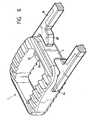
- the cage 1 described above is particularly adapted to allow its manipulation by a gripper 15, as illustrated in FIGS. Fig. 4 and 5 , having two branches 16 each provided at each end with a gripping jaw 17.
- the cage 1 comprises two housings 20 extending in the extension of one another and adapted to each receive a radial stud 21 provided on each jaw 17 of the clamp.
- the housings 20 are made on the sagittal walls 2 and 3 while being aligned and extending in a frontal direction perpendicular to the sagittal plane S.
- the housings 20 are arranged, preferably, near the wall 4.
- each housing 20 opens on the two opposite vertical faces of the walls 2 and 3.
- the two housings 20 can communicate with each other directly to form a single bore.
- the housings 20 have a transverse cross section adapted to receive a radial stud 21 and, for example, substantially elliptical in the illustrated example.
- the cage 1 comprises anti-rotation means 23 intended to cooperate with complementary means 24 arranged on the jaws 17 of the gripper, so as to obtain, in the gripping position of the cage by the clamp, a relatively rotational locking between the cage 1 and the clamp 15.
- these anti-rotation means 23 are constituted by a groove arranged in each sagittal wall 2, 3 to open in a corresponding housing 20 and extending to the outer face of the front transverse wall 4. As illustrated more particularly in the Fig. 3 Each groove 23 has a rectangular transverse cross section.
- each gripping jaw 17 is arranged to provide, as complementary anti-rotation means 24, an arm or a bar provided, at its free end, with a radial stud 21 extending in alignment with one of the other.
- Each arm 24, which has a complementary cross section of the groove 23, is intended to be engaged at least in part, in the groove 23 arranged on a sagittal wall when each pin 21 is engaged in a complementary housing 20.
- the cage 1 described above is particularly adapted to respect the shape of the disc space defined between two vertebrae, for example cervical.
- the respect of the anatomy of the intervertebral disc replaced by the cage 1 promotes the bone fusion between the vertebrae and the restoration of the spinal statics.
- the establishment of the cage 1 is particularly simplified by the use of the gripper 15 .
- a cage 1 can be taken by the clamp 15 by ensuring, by an action on the branches 16 to move the jaws 17, the relative positioning between the pins 21 and the housing 20, and by an action on the branches to bring the jaws 17, the engagement, on the one hand, pins 21 in the housing 20 and, on the other hand, arms 24 in the grooves 23.
- the grooves 23 are able to provide a function guide for the pins 21 which are brought to the housing, in order to enter.
- the cage 1 is perfectly locked relative to the clamp, thanks to the engagement of the pins 21 in the housing 20 and arms 24 in the grooves 23, 4.
- the cage 1 can be introduced into the disc space possibly with the application of thrust forces on the end 30 of the clamp.
- An action on the branches 16 to move the jaws 17 ensures the clearance of the pins 21 of the housing 20, for the withdrawal of the clamp.
Landscapes
- Health & Medical Sciences (AREA)
- Engineering & Computer Science (AREA)
- Biomedical Technology (AREA)
- Orthopedic Medicine & Surgery (AREA)
- Transplantation (AREA)
- Neurology (AREA)
- Oral & Maxillofacial Surgery (AREA)
- Cardiology (AREA)
- Heart & Thoracic Surgery (AREA)
- Vascular Medicine (AREA)
- Life Sciences & Earth Sciences (AREA)
- Animal Behavior & Ethology (AREA)
- General Health & Medical Sciences (AREA)
- Public Health (AREA)
- Veterinary Medicine (AREA)
- Physical Education & Sports Medicine (AREA)
- Prostheses (AREA)
- Surgical Instruments (AREA)
- Magnetic Resonance Imaging Apparatus (AREA)
Description
- La présente invention concerne un implant intersomatique destiné à être inséré dans l'espace discal défini entre deux vertèbres adjacentes, en vue de restituer une hauteur convenable intervertébrale et d'assurer une fusion osseuse entre lesdites vertèbres adjacentes.
- L'objet de l'invention vise, plus précisément, un implant intersomatique du type cervical, destiné à être logé dans l'espace discal défini entre deux vertèbres cervicales adjacentes.
- Dans l'état de la technique, il est connu d'insérer un implant intersomatique dans l'espace discal défini entre deux vertèbres cervicales adjacentes. De nombreuses formes de réalisation de tels implants intersomatiques ont été proposées dans l'art antérieur. Par exemple, il est connu par le document
FR 2 703 580 - Pour respecter au mieux l'anatomie de la colonne vertébrale, le document
US-A 683 464 décrit un implant intersomatique comportant des faces transversales qui peuvent avoir des profils convexes dans le plan sagittal et/ou dans le plan frontal. De même, le documentUS-A-5 865 845 propose un implant intervertébral où les profils des deux faces transversales sont convexes et congruents aux profils des vertèbres sus et sous-jacentes dans le plan sagittal. Le profil des faces transversales de cet implant dans le plan frontal est concave ou plan. - D'une manière générale, il doit être considéré que l'insertion d'un implant du type décrit dans l'art antérieur, dans l'espace discal de deux vertèbres adjacentes est susceptible de conduire à un positionnement incorrect des vertèbres entre elles. Il s'ensuit qu'il ne peut pas être obtenu une bonne reconstitution osseuse entre les vertèbres concernées.
- L'objet de l'invention vise donc à remédier aux inconvénients énoncés ci-dessus en proposant un implant intersomatique adapté pour respecter au mieux l'anatomie de la colonne vertébrale.
- Pour atteindre un tel objectif, l'implant intersomatique selon l'invention est conforme à la revendication 1
- Diverses autres caractéristiques ressortent de la description faite ci-dessous en référence aux dessins annexés qui montrent, à titre d'exemples non limitatifs, des formes de réalisation et de mise en oeuvre de l'objet de l'invention.
-
- La
fig. 1 est une vue en perspective d'un exemple de réalisation d'un implant conforme à l'invention. - La
fig. 2 est une vue frontale d'un implant prise sensiblement selon la flèche f2 de lafig. 1 . - La
fig. 3 est une vue sagittale d'un implant prise sensiblement selon la flèche f3 de lafig. 1 . - La
fig. 4 est une vue de dessus d'une pince de préhension d'un implant conforme à l'invention. - La
fig. 5 est une vue en perspective montrant un implant intersomatique supporté par une pince de préhension. - Tel que cela apparaît plus précisément aux
fig. 1 à 3 , l'implant intersomatique conforme à l'invention se présente sous la forme d'une cage 1 présentant une forme générale parallélèpipédique et destinée à être insérée dans l'espace discal entre deux vertèbres adjacentes, par exemple cervicales. La cage 1 comporte une première paroi sagittale 2 et une seconde paroi sagittale 3 s'étendant sensiblement parallèlement l'une à l'autre et à un plan S dit sagittal ou antéro-postérieur. Les parois sagittales 2 et 3 sont reliées entre elles par une paroi transversale, dite antérieure 4, et par une paroi transversale, dite postérieure 5 s'étendant parallèlement l'une à l'autre et à un plan frontal F perpendiculaire au plan sagittal S. - Il est à noter que la cage 1 peut comporter une ou plusieurs parois médianes ou intermédiaires s'étendant sensiblement parallèlement aux parois transversales et/ou sagittales. De préférence, des congés de raccordement 6 sont aménagés entre les parois sagittales et les parois transversales, d'une part, selon leurs faces verticales internes et, d'autre part, selon leurs faces verticales externes, permettant de disposer d'une cage 1 avec des coins arrondis sur ses faces verticales externes et internes. Par exemple, les parois 2 à 5 présentent une épaisseur sensiblement de même valeur. De même, la hauteur de la paroi transversale antérieure 4 présente une valeur supérieure à la hauteur de la paroi transversale postérieure 5 (
fig. 3 ). - La cage 1 présente intérieurement un volume 7 délimité par les faces verticales internes des parois 2 à 5 et destiné à être rempli par un produit de comblement osseux destiné à la fusion intersomatique. Ce volume 7 s'ouvre selon une première face transversale 8, dite supérieure dans l'exemple illustré, et une deuxième face transversale 9, dite inférieure dans l'exemple considéré. Les parois 2 à 5 présentent, d'un côté, des rebords 10 délimitant la face transversale supérieure 8 et, de l'autre côté, des rebords 10' délimitant la face transversale inférieure 9.
- La cage 1 comporte des protubérances ou des saillies 11 aménagées sur les rebords 10, 10' des parois 2 à 5 pour permettre un accrochage de la cage sur les vertèbres sus et sous-jacentes. Les protubérances 11 sont constituées dans l'exemple préféré illustré, par des crans s'étendant parallèlement les uns des autres et par rapport au plan frontal F. Bien entendu, les protubérances peuvent présenter des formes différentes et être réalisées, par exemple, par des picots individuels ou par des crans en forme de chevrons. D'une manière générale, il doit être compris que les faces transversales supérieure 8 et inférieure 9 correspondent à l'enveloppe passant par le sommet des protubérances 11.
- Selon une caractéristique de l'invention qui est illustrée plus précisément à la
fig. 3 , la face transversale supérieure 8 présente dans le plan sagittal S, un profil convexe C8 congruent ou complémentaire du profil anatomique sagittal d'une vertèbre voisine ou sus-jacente dans l'exemple illustré. Il doit être compris que les rebords 10 des parois et, plus précisément, les protubérances 11 délimitant cette face transversale supérieure 8, sont aménagés pour s'inscrire dans une enveloppe dont la section dans le plan sagittal S, est de forme bombée ou convexe. - Selon une autre caractéristique préférée de réalisation, la face transversale supérieure 8 est délimitée dans le plan frontal F par un profil rectiligne ou droit C'8 (
fig. 2 ). De préférence, les rebords 10 des parois 2 à 5 délimitant la face transversale supérieure 8 sont aménagés pour être raccordés aux faces extérieures des parois 2 à 5 par des congés de raccordement 12. - Selon une autre caractéristique de l'invention qui apparaît plus précisément à la
fig. 2 , la face transversale inférieure 9 présente, dans le plan frontal F, un profil convexe C9 congruent ou complémentaire au profil anatomique frontal d'une vertèbre voisine ou sous-jacente dans l'exemple illustré. Les rebords 10' des parois 2 à 5 et, plus précisément, les protubérances 11 délimitant cette face transversale 9 sont aménagées pour s'inscrire dans une enveloppe dont la section dans le plan S, est de forme bombée. - Par ailleurs, il est à noter que la face transversale inférieure 9 présente, dans le plan sagittal, un profil C'9 qui est sensiblement droit.
- Avantageusement, la cage 1 décrite ci-dessus est adaptée pour recevoir au moins un et, dans l'exemple illustré, deux repères radio-opaques 13 incorporés sur au moins une partie de la hauteur de la cage au niveau des parois transversales antérieure 4 et postérieure 5.
- La cage 1 décrite ci-dessus est particulièrement adaptée pour permettre sa manipulation par une pince de préhension 15, telle qu'illustrée aux
fig. 4 et5 , comportant deux branches 16 munies chacune, à chaque extrémité, d'un mors de préhension 17. - A cet effet, la cage 1 comporte deux logements 20 s'étendant dans le prolongement l'un de l'autre et adaptés pour recevoir chacun un téton radial 21 aménagé sur chaque mors 17 de la pince. Dans l'exemple illustré, les logements 20 sont réalisés sur les parois sagittales 2 et 3 en étant alignés et en s'étendant selon une direction frontale perpendiculaire au plan sagittal S. Les logements 20 sont aménagés, de préférence, à proximité de la paroi transversale antérieure 4. Dans l'exemple illustré, chaque logement 20 débouche sur les deux faces verticales opposées des parois 2 et 3. Bien entendu, il peut être prévu de réaliser les logements 20 au niveau de la paroi transversale antérieure 4 en s'étendant selon une direction frontale perpendiculaire au plan sagittal S. Dans cette forme de réalisation, il est à noter que les deux logements 20 peuvent comnuniquer entre-eux directement pour constituer un alésage unique. Les logements 20 possèdent une section droite transversale adaptée pour recevoir un téton radial 21 et, par exemple, sensiblement elliptique dans l'exemple illustré.
- Selon une caractéristique préférée de réalisation, la cage 1 comporte des moyens 23 d'anti-rotation destinés à coopérer avec des moyens complémentaires 24 aménagés sur les mors 17 de la pince de préhension, de manière à obtenir, en position de préhension de la cage par la pince, un blocage relatif en rotation entre la cage 1 et la pince 15. Dans l'exemple illustré, ces moyens d'anti-rotation 23 sont constitués par une rainure aménagée dans chaque paroi sagittale 2, 3 pour s'ouvrir dans un logement 20 correspondant et en s'étendant jusqu'à la face externe de la paroi transversale antérieure 4. Comme illustré plus particulièrement à la
fig. 3 , chaque rainure 23 possède une section droite transversale rectangulaire. - Tel que cela apparaît plus précisément aux
fig. 4 et5 , chaque mors de préhension 17 est aménagé pour présenter, en tant que moyen d'anti-rotation complémentaire 24, un bras ou un barreau pourvu, à son extrémité libre, d'un téton radial 21 s'étendant en alignement l'un de l'autre. Chaque bras 24, qui présente une section transversale complémentaire de la rainure 23, est destiné à être engagé au moins en partie, dans la rainure 23 aménagée sur une paroi sagittale lorsque chaque téton 21 est engagé dans un logement complémentaire 20. - L'engagement des tétons 21 dans les logements 20 assure la préhension de la cage et son blocage en translation, tandis que la coopération des bras 24 avec les rainures 23 permet d'obtenir un blocage en rotation, notamment selon une direction frontale. Il s'ensuit un blocage complet de la cage par les mors de préhension 17. Il est à noter qu'il pourrait être envisagé de réaliser de manière différente, les moyens d'antirotation 23, 24. Par exemple, il pourrait être prévu de réaliser des logements 20 de forme prismatique destinés à coopérer avec des tétons de forme complémentaire.
- La cage 1 décrite ci-dessus est particulièrement adaptée pour respecter la forme de l'espace discal défini entre deux vertèbres, par exemple cervicales. Le respect de l'anatomie du disque intervertébral remplacé par la cage 1 favorise la fusion osseuse entre les vertèbres et la restauration de la statique rachidienne. De plus, la mise en place de la cage 1 est particulièrement simplifiée par l'utilisation de la pince de préhension 15. Ainsi, à partir d'une voie d'abord antérieure du rachis cervical, il est procédé à une résection des ostéophytes, à une dissectomie, puis à un avivement des plateaux des vertèbres. Ensuite, une cage 1 peut être prise par la pince 15 en assurant, par une action sur les branches 16 pour écarter les mors 17, le positionnement relatif entre les tétons 21 et les logements 20, et par une action sur les branches pour rapprocher les mors 17, l'engagement, d'une part, des tétons 21 dans les logements 20 et, d'autre part, des bras 24 dans les rainures 23. Il est à noter que les rainures 23 sont à même d'assurer une fonction de guidage pour les tétons 21 qui se trouvent amenés jusqu'au logement, afin de s'y introduire. Dans cette position, la cage 1 est parfaitement bloquée par rapport à la pince, grâce à l'engagement des tétons 21 dans les logements 20 et des bras 24 dans les rainures 23, 4. La cage 1 peut être introduite dans l'espace discal avec éventuellement l'application d'efforts de poussée sur l'extrémité 30 de la pince. Une action sur les branches 16 pour écarter les mors 17 permet d'assurer le dégagement des tétons 21 des logements 20, en vue du retrait de la pince.
- L'invention n'est pas limitée aux exemples décrits et représentés, car diverses modifications peuvent y être apportées sans sortir de son cadre.
Claims (7)
- Implant intersomatique destiné à être inséré dans l'espace discal défini entre deux vertèbres voisines, dites sus et sous-jacentes, en vue du rétablissement anatomique de l'espace intervertébral, l'implant se présentant sous la forme d'une cage (1) de forme générale parallélépipédique comportant au moins deux parois sagittales (2, 3) sensiblement parallèles à un plan sagittal (S) et reliées entre elles par au moins des parois transversales antérieure (4) et postérieure (5) sensiblement parallèles à un plan frontal (F), les parois (2 à 5) délimitant entre elles un volume ouvert (7) pour un remplissage osseux et présentant des rebords (10, 10') s'étendant d'un côté pour délimiter une première face transversale (8) et de l'autre côté, pour délimiter une deuxième face transversale (9), le profil (C8, C9) de chaque face transversale (8, 9) étant délimité par des protubérances (11) aménagées sur les rebords (10, 10') des parois sagittales et frontales,
caractérisé en ce que :- la première face transversale (8) présente dans le plan sagittal, un profil convexe (C8 ) destiné à être congruent au profil anatomique sagittal d'une vertèbre sus-jacente,- la deuxième face transversale présente dans le plan frontal, un profil convexe (C9 ) destiné à être congruent au profil anatomique frontal d'une vertèbre sous-jacente. - Implant selon la revendication 1, caractérisé en ce que les rebords (10, 10') des parois sagittales et frontales comportent des protubérances (11) formant des crans s'étendant parallèlement les uns des autres et par rapport au plan frontal (F).
- Implant selon la revendication 1 ou 2, caractérisé en ce qu'il comporte au moins un repère radio opaque (13) s'étendant au moins sur une partie de la hauteur d'une paroi.
- Implant selon l'une des revendications 1 à 3, caractérisé en ce qu'il comporte deux logements de réception (20) pour les mors (17) d'une pince de préhension, les logements s'étendant sensiblement en vis-à-vis selon une direction frontale perpendiculaire au plan sagittal (S) de la cage.
- Implant selon la revendication 4, caractérisé en ce que chaque logement (20) s'ouvre au moins sur la face externe d'une paroi sagittale (2, 3).
- Implant selon la revendication 4 ou 5, caractérisé en ce que les parois sont aménagées pour comporter des moyens d'anti-rotation (23) destinés à coopérer avec des moyens complémentaires (24) aménagés sur les mors (17) de la pince de préhension, de manière à obtenir, en position de préhension de la cage par la pince, un blocage relatif entre la cage et la pince.
- Implant selon la revendication 6, caractérisé en ce que chaque logement (20) s'ouvre sur les parois sagittales (2, 3) dans une rainure (23) s'étendant jusqu'à la face externe de la paroi antérieure pour constituer les moyens d'anti-rotation et permettre l'insertion des mors d'une pince de préhension.
Applications Claiming Priority (3)
| Application Number | Priority Date | Filing Date | Title |
|---|---|---|---|
| FR9909122A FR2795945B1 (fr) | 1999-07-09 | 1999-07-09 | Implant intersomatique anatomique et pince de prehension pour un tel implant |
| FR9909122 | 1999-07-09 | ||
| PCT/FR2000/001967 WO2001003615A1 (fr) | 1999-07-09 | 2000-07-07 | Implant intersomatique anatomique et pince de prehension pour un tel implant |
Publications (2)
| Publication Number | Publication Date |
|---|---|
| EP1194087A1 EP1194087A1 (fr) | 2002-04-10 |
| EP1194087B1 true EP1194087B1 (fr) | 2008-08-27 |
Family
ID=9548084
Family Applications (1)
| Application Number | Title | Priority Date | Filing Date |
|---|---|---|---|
| EP00949674A Expired - Lifetime EP1194087B1 (fr) | 1999-07-09 | 2000-07-07 | Implant intersomatique anatomique |
Country Status (9)
| Country | Link |
|---|---|
| US (2) | US6964687B1 (fr) |
| EP (1) | EP1194087B1 (fr) |
| AT (1) | ATE406147T1 (fr) |
| AU (1) | AU6295700A (fr) |
| DE (1) | DE60040071D1 (fr) |
| ES (1) | ES2312357T3 (fr) |
| FR (1) | FR2795945B1 (fr) |
| PT (1) | PT1194087E (fr) |
| WO (1) | WO2001003615A1 (fr) |
Cited By (8)
| Publication number | Priority date | Publication date | Assignee | Title |
|---|---|---|---|---|
| US9192419B2 (en) | 2008-11-07 | 2015-11-24 | DePuy Synthes Products, Inc. | Zero-profile interbody spacer and coupled plate assembly |
| US9216096B2 (en) | 2010-03-16 | 2015-12-22 | Pinnacle Spine Group, Llc | Intervertebral implants and related tools |
| US9220604B2 (en) | 2010-12-21 | 2015-12-29 | DePuy Synthes Products, Inc. | Intervertebral implants, systems, and methods of use |
| US9241809B2 (en) | 2010-12-21 | 2016-01-26 | DePuy Synthes Products, Inc. | Intervertebral implants, systems, and methods of use |
| US9380932B1 (en) | 2011-11-02 | 2016-07-05 | Pinnacle Spine Group, Llc | Retractor devices for minimally invasive access to the spine |
| US9463097B2 (en) | 2003-02-06 | 2016-10-11 | DePuy Synthes Products, Inc. | Intervertebral implant |
| US9572681B2 (en) | 2002-02-19 | 2017-02-21 | DePuy Synthes Products, Inc. | Intervertebral implant |
| US10070970B2 (en) | 2013-03-14 | 2018-09-11 | Pinnacle Spine Group, Llc | Interbody implants and graft delivery systems |
Families Citing this family (192)
| Publication number | Priority date | Publication date | Assignee | Title |
|---|---|---|---|---|
| US5609635A (en) * | 1988-06-28 | 1997-03-11 | Michelson; Gary K. | Lordotic interbody spinal fusion implants |
| US8545569B2 (en) | 2001-05-25 | 2013-10-01 | Conformis, Inc. | Patient selectable knee arthroplasty devices |
| US8480754B2 (en) | 2001-05-25 | 2013-07-09 | Conformis, Inc. | Patient-adapted and improved articular implants, designs and related guide tools |
| US8617242B2 (en) | 2001-05-25 | 2013-12-31 | Conformis, Inc. | Implant device and method for manufacture |
| US9603711B2 (en) | 2001-05-25 | 2017-03-28 | Conformis, Inc. | Patient-adapted and improved articular implants, designs and related guide tools |
| US7799077B2 (en) | 2002-10-07 | 2010-09-21 | Conformis, Inc. | Minimally invasive joint implant with 3-dimensional geometry matching the articular surfaces |
| US8735773B2 (en) | 2007-02-14 | 2014-05-27 | Conformis, Inc. | Implant device and method for manufacture |
| US8771365B2 (en) | 2009-02-25 | 2014-07-08 | Conformis, Inc. | Patient-adapted and improved orthopedic implants, designs, and related tools |
| US8556983B2 (en) | 2001-05-25 | 2013-10-15 | Conformis, Inc. | Patient-adapted and improved orthopedic implants, designs and related tools |
| US8882847B2 (en) | 2001-05-25 | 2014-11-11 | Conformis, Inc. | Patient selectable knee joint arthroplasty devices |
| US7239908B1 (en) | 1998-09-14 | 2007-07-03 | The Board Of Trustees Of The Leland Stanford Junior University | Assessing the condition of a joint and devising treatment |
| DE69941304D1 (de) | 1998-09-14 | 2009-10-01 | Univ R | Zustandsbestimmung eines gelenks und schadenvorsorge |
| EP1253854A4 (fr) | 1999-03-07 | 2010-01-06 | Discure Ltd | Procede et appareil de chirurgie informatisee |
| EP1194088B1 (fr) | 1999-07-02 | 2008-03-12 | Spine Solutions Inc. | Implant intervertebral |
| FR2897259B1 (fr) | 2006-02-15 | 2008-05-09 | Ldr Medical Soc Par Actions Si | Cage intersomatique transforaminale a greffon de fusion intervetebrale et instrument d'implantation de la cage |
| BR9917485A (pt) | 1999-09-14 | 2002-05-14 | Spine Solutions Inc | Instrumento de inserção para um implante entre vértebras de três partes |
| FR2799639B1 (fr) * | 1999-10-18 | 2002-07-19 | Dimso Sa | Prothese de disque intervertebral a faces dentees |
| EP1138285A1 (fr) * | 2000-03-29 | 2001-10-04 | Implant Design AG | Cage vertébrale pour poser entre les vertèbres de la colonne vertébrale |
| US7226480B2 (en) * | 2000-08-15 | 2007-06-05 | Depuy Spine, Inc. | Disc prosthesis |
| WO2002022014A1 (fr) | 2000-09-14 | 2002-03-21 | The Board Of Trustees Of The Leland Stanford Junior University | Évaluation de l'état d'une articulation et traitement afférent |
| EP1322224B1 (fr) | 2000-09-14 | 2008-11-05 | The Board Of Trustees Of The Leland Stanford Junior University | Evaluation de l'etat d'une articulation et d'une perte de cartilage |
| US8940047B2 (en) * | 2001-02-15 | 2015-01-27 | Spinecore, Inc. | Intervertebral spacer device having recessed notch pairs for manipulation using a surgical tool |
| JP2005504563A (ja) | 2001-05-25 | 2005-02-17 | イメージング セラピューティクス,インコーポレーテッド | 関節を再表面化する方法および組成物 |
| US20070156171A1 (en) * | 2001-05-25 | 2007-07-05 | Conformis, Inc. | Implant Grasper |
| FR2827157B1 (fr) * | 2001-07-10 | 2004-04-09 | Vitatech | Implant intersomatique pour vertebres cervicales |
| JP4295086B2 (ja) | 2001-07-11 | 2009-07-15 | ヌバシブ, インコーポレイテッド | 手術の間の神経近接度、神経の方向、および病理学を決定するシステムおよび方法 |
| FR2827156B1 (fr) * | 2001-07-13 | 2003-11-14 | Ldr Medical | Dispositif de cage vertebrale avec fixation modulaire |
| NL1018583C2 (nl) * | 2001-07-19 | 2003-01-21 | Gtg | Kunstmatige tussenwervelschijf alsmede werkwijzen voor het vervaardigen en aanbrengen daarvan. |
| EP1435828A4 (fr) | 2001-09-25 | 2009-11-11 | Nuvasive Inc | Systeme et procedes pour evaluations et actes chirurgicaux |
| CA2460028A1 (fr) * | 2001-10-30 | 2003-05-08 | Osteotech, Inc. | Implant osseux et intruments d'insertion |
| US7238203B2 (en) | 2001-12-12 | 2007-07-03 | Vita Special Purpose Corporation | Bioactive spinal implants and method of manufacture thereof |
| US7674297B2 (en) * | 2002-06-14 | 2010-03-09 | U.S. Spinal Technologies, Llc | Anatomic vertebral cage |
| US7582058B1 (en) | 2002-06-26 | 2009-09-01 | Nuvasive, Inc. | Surgical access system and related methods |
| US8137284B2 (en) | 2002-10-08 | 2012-03-20 | Nuvasive, Inc. | Surgical access system and related methods |
| US7063725B2 (en) * | 2002-10-21 | 2006-06-20 | Sdgi Holdings, Inc. | Systems and techniques for restoring and maintaining intervertebral anatomy |
| US7125425B2 (en) * | 2002-10-21 | 2006-10-24 | Sdgi Holdings, Inc. | Systems and techniques for restoring and maintaining intervertebral anatomy |
| US7232463B2 (en) * | 2002-10-23 | 2007-06-19 | U.S. Spinal Technologies, Llc | Intervertebral cage designs |
| WO2004043305A1 (fr) | 2002-11-07 | 2004-05-27 | Conformis, Inc. | Procedes pour determiner les dimensions et formes de menisques, et pour mettre au point un traitement |
| US7204852B2 (en) | 2002-12-13 | 2007-04-17 | Spine Solutions, Inc. | Intervertebral implant, insertion tool and method of inserting same |
| US7192447B2 (en) | 2002-12-19 | 2007-03-20 | Synthes (Usa) | Intervertebral implant |
| US7691057B2 (en) | 2003-01-16 | 2010-04-06 | Nuvasive, Inc. | Surgical access system and related methods |
| US7491204B2 (en) | 2003-04-28 | 2009-02-17 | Spine Solutions, Inc. | Instruments and method for preparing an intervertebral space for receiving an artificial disc implant |
| US7320689B2 (en) * | 2003-07-15 | 2008-01-22 | Cervitech, Inc. | Multi-part cervical endoprosthesis with insertion instrument |
| US20050015095A1 (en) * | 2003-07-15 | 2005-01-20 | Cervitech, Inc. | Insertion instrument for cervical prostheses |
| US7803162B2 (en) * | 2003-07-21 | 2010-09-28 | Spine Solutions, Inc. | Instruments and method for inserting an intervertebral implant |
| DE50307429D1 (de) | 2003-08-04 | 2007-07-19 | Cervitech Inc | Zervikalprothese mit Einsetzinstrument |
| AU2004275877B2 (en) | 2003-09-25 | 2008-09-04 | Nuvasive, Inc. | Surgical access system and related methods |
| US7905840B2 (en) | 2003-10-17 | 2011-03-15 | Nuvasive, Inc. | Surgical access system and related methods |
| US20050071005A1 (en) * | 2003-09-30 | 2005-03-31 | Olivier Carli | Intersomatic lumbar implant |
| KR101146215B1 (ko) | 2004-02-04 | 2012-05-11 | 엘디알 메디칼 | 추간 연골 인공 기관 |
| US7918891B1 (en) | 2004-03-29 | 2011-04-05 | Nuvasive Inc. | Systems and methods for spinal fusion |
| US7988699B2 (en) | 2004-10-19 | 2011-08-02 | Warsaw Orthopedic, Inc. | Adjustable instrumentation for spinal implant insertion |
| US7875080B2 (en) | 2004-11-10 | 2011-01-25 | Warsaw Orthopedic, Inc. | Intervertebral spacer |
| US8172855B2 (en) | 2004-11-24 | 2012-05-08 | Abdou M S | Devices and methods for inter-vertebral orthopedic device placement |
| USD530423S1 (en) * | 2005-03-29 | 2006-10-17 | Nuvasive, Inc. | Intervertebral implant |
| US8585766B2 (en) | 2005-05-06 | 2013-11-19 | Titan Spine, Llc | Endplate-preserving spinal implant with an integration plate having durable connectors |
| US8758443B2 (en) | 2005-05-06 | 2014-06-24 | Titan Spine, Llc | Implants with integration surfaces having regular repeating surface patterns |
| US11096796B2 (en) * | 2005-05-06 | 2021-08-24 | Titan Spine, Llc | Interbody spinal implant having a roughened surface topography on one or more internal surfaces |
| US8992622B2 (en) | 2005-05-06 | 2015-03-31 | Titan Spine, Llc | Interbody spinal implant having a roughened surface topography |
| US8814939B2 (en) | 2005-05-06 | 2014-08-26 | Titan Spine, Llc | Implants having three distinct surfaces |
| US8617248B2 (en) | 2005-05-06 | 2013-12-31 | Titan Spine, Llc | Spinal implant having variable ratios of the integration surface area to the axial passage area |
| US8591590B2 (en) * | 2005-05-06 | 2013-11-26 | Titan Spine, Llc | Spinal implant having a transverse aperture |
| US8758442B2 (en) | 2005-05-06 | 2014-06-24 | Titan Spine, Llc | Composite implants having integration surfaces composed of a regular repeating pattern |
| US8562684B2 (en) | 2005-05-06 | 2013-10-22 | Titan Spine, Llc | Endplate-preserving spinal implant with an integration plate having a roughened surface topography |
| US9125756B2 (en) | 2005-05-06 | 2015-09-08 | Titan Spine, Llc | Processes for producing regular repeating patterns on surfaces of interbody devices |
| US8262737B2 (en) | 2005-05-06 | 2012-09-11 | Titan Spine, Llc | Composite interbody spinal implant having openings of predetermined size and shape |
| US8585767B2 (en) | 2005-05-06 | 2013-11-19 | Titan Spine, Llc | Endplate-preserving spinal implant with an integration plate having durable connectors |
| US8585765B2 (en) | 2005-05-06 | 2013-11-19 | Titan Spine, Llc | Endplate-preserving spinal implant having a raised expulsion-resistant edge |
| US9168147B2 (en) | 2005-05-06 | 2015-10-27 | Titan Spine, Llc | Self-deploying locking screw retention device |
| US8562685B2 (en) | 2005-05-06 | 2013-10-22 | Titan Spine, Llc | Spinal implant and integration plate for optimizing vertebral endplate contact load-bearing edges |
| US8551176B2 (en) | 2005-05-06 | 2013-10-08 | Titan Spine, Llc | Spinal implant having a passage for enhancing contact between bone graft material and cortical endplate bone |
| US8623088B1 (en) | 2005-07-15 | 2014-01-07 | Nuvasive, Inc. | Spinal fusion implant and related methods |
| US8147521B1 (en) | 2005-07-20 | 2012-04-03 | Nuvasive, Inc. | Systems and methods for treating spinal deformities |
| WO2007016247A2 (fr) | 2005-07-28 | 2007-02-08 | Nuvasive, Inc. | Systeme de remplacement de disque entier et methodes associees |
| FR2891135B1 (fr) | 2005-09-23 | 2008-09-12 | Ldr Medical Sarl | Prothese de disque intervertebral |
| USD533277S1 (en) * | 2005-11-04 | 2006-12-05 | Quantum Orthopedics, Inc. | Interbody fusion device |
| USD524443S1 (en) * | 2005-11-04 | 2006-07-04 | Quantum Orthopedics, Inc. | Interbody fusion device |
| FR2893838B1 (fr) * | 2005-11-30 | 2008-08-08 | Ldr Medical Soc Par Actions Si | Prothese de disque intervertebral et instrumentation d'insertion de la prothese entre les vertebres |
| US7901458B2 (en) * | 2005-12-16 | 2011-03-08 | Warsaw Orthopedic, Inc. | Intervertebral spacer and insertion tool |
| EP1988855A2 (fr) | 2006-02-27 | 2008-11-12 | Synthes GmbH | Implant intervertebral avec geometrie de fixation |
| RU2319473C2 (ru) * | 2006-04-24 | 2008-03-20 | ФГУ Новосибирский научно-исследовательский институт травматологии и ортопедии (ФГУ ННИИТО Росздрава) | Межтеловой эндофиксатор |
| USD741488S1 (en) | 2006-07-17 | 2015-10-20 | Nuvasive, Inc. | Spinal fusion implant |
| WO2008014258A2 (fr) | 2006-07-24 | 2008-01-31 | Spine Solutions, Inc. | Implant intervertébral avec quille |
| US8337500B2 (en) | 2006-07-31 | 2012-12-25 | Synthes Usa, Llc | Drilling/milling guide and keel cut preparation system |
| WO2008020263A1 (fr) * | 2006-08-18 | 2008-02-21 | Querol Garcia Valeria | Système de prise ambidextre pour jeu d'instruments médicaux |
| ES2328879B1 (es) * | 2006-10-27 | 2010-09-16 | Traiber, S.A. | Caja intersomatica, pinza para manipulacion de la misma y procedimiento de introduccion de la caja intersomatica entre vertebras. |
| US8034081B2 (en) | 2007-02-06 | 2011-10-11 | CollabComl, LLC | Interspinous dynamic stabilization implant and method of implanting |
| USD566842S1 (en) | 2007-02-19 | 2008-04-15 | Zimmer Spine, Inc. | Spinal implant |
| USD611147S1 (en) * | 2007-02-27 | 2010-03-02 | Zimmer Spine, Inc. | Spinal implant |
| USD595853S1 (en) * | 2007-02-27 | 2009-07-07 | Zimmer Spine, Inc. | Spinal implant |
| US8673005B1 (en) | 2007-03-07 | 2014-03-18 | Nuvasive, Inc. | System and methods for spinal fusion |
| FR2916956B1 (fr) | 2007-06-08 | 2012-12-14 | Ldr Medical | Cage intersomatique,prothese intervertebrale,dispositif d'ancrage et instrumentation d'implantation |
| US20090062917A1 (en) | 2007-08-27 | 2009-03-05 | Foley Kevin T | Spinal interbody replacement devices |
| USD671645S1 (en) | 2007-09-18 | 2012-11-27 | Nuvasive, Inc. | Intervertebral implant |
| US8852280B2 (en) | 2007-09-27 | 2014-10-07 | Warsaw Orthopedic, Inc. | Intervertebral implant |
| US7845941B2 (en) * | 2007-11-02 | 2010-12-07 | Mark Minium | Orthodontic instrument for use with adjustable orthodontic apparatus |
| JP2011502708A (ja) | 2007-11-16 | 2011-01-27 | ジンテス ゲゼルシャフト ミット ベシュレンクテル ハフツング | 低輪郭の椎間インプラント |
| US9101491B2 (en) | 2007-12-28 | 2015-08-11 | Nuvasive, Inc. | Spinal surgical implant and related methods |
| US8083796B1 (en) | 2008-02-29 | 2011-12-27 | Nuvasive, Inc. | Implants and methods for spinal fusion |
| WO2009111656A1 (fr) * | 2008-03-05 | 2009-09-11 | Conformis, Inc. | Implant articulaire à bords concordants |
| WO2009111626A2 (fr) | 2008-03-05 | 2009-09-11 | Conformis, Inc. | Implants pour modifier des modèles d’usure de surfaces articulaires |
| USD599019S1 (en) * | 2008-03-07 | 2009-08-25 | Nuvasive, Inc. | Spinal fusion implant |
| JP2011519713A (ja) | 2008-05-12 | 2011-07-14 | コンフォーミス・インコーポレイテッド | 面関節および他の関節の治療のためのデバイスならびに方法 |
| USD619255S1 (en) * | 2008-07-26 | 2010-07-06 | Ulrich Gmbh & Co. Kg | Spinal implant |
| US8147554B2 (en) * | 2008-10-13 | 2012-04-03 | Globus Medical, Inc. | Intervertebral spacer |
| USD621509S1 (en) * | 2008-10-15 | 2010-08-10 | Nuvasive, Inc. | Intervertebral implant |
| USD653756S1 (en) * | 2008-12-02 | 2012-02-07 | Eminent Spine Llc | Interbody fusion device implant |
| USD620110S1 (en) * | 2008-12-02 | 2010-07-20 | Eminent Spine Llc | Interbody fusion device implant |
| US8425603B2 (en) | 2008-12-22 | 2013-04-23 | Synthes Usa, Llc | Orthopedic implant with flexible keel |
| FR2941365B1 (fr) * | 2009-01-27 | 2011-03-18 | Acmel Ind | Outil d'implantation et de fixation d'une cage intervertebrale |
| EP2405865B1 (fr) | 2009-02-24 | 2019-04-17 | ConforMIS, Inc. | Systèmes automatisés four la fabrication des implants et instruments adaptés individuellement au patient |
| USD754346S1 (en) | 2009-03-02 | 2016-04-19 | Nuvasive, Inc. | Spinal fusion implant |
| US9387090B2 (en) | 2009-03-12 | 2016-07-12 | Nuvasive, Inc. | Vertebral body replacement |
| US9687357B2 (en) | 2009-03-12 | 2017-06-27 | Nuvasive, Inc. | Vertebral body replacement |
| US8287597B1 (en) | 2009-04-16 | 2012-10-16 | Nuvasive, Inc. | Method and apparatus for performing spine surgery |
| US9351845B1 (en) | 2009-04-16 | 2016-05-31 | Nuvasive, Inc. | Method and apparatus for performing spine surgery |
| USD625820S1 (en) * | 2009-06-05 | 2010-10-19 | Globus Medical, Inc. | Lateral fusion implant |
| USD629104S1 (en) * | 2009-06-05 | 2010-12-14 | Globus Medical, Inc. | Lordotic lateral fusion implant |
| US9095444B2 (en) | 2009-07-24 | 2015-08-04 | Warsaw Orthopedic, Inc. | Implant with an interference fit fastener |
| CA2773723C (fr) | 2009-09-17 | 2017-10-31 | Synthes Usa, Llc | Implant intervertebral comportant des elements de fixation d'os extensibles |
| USD731063S1 (en) | 2009-10-13 | 2015-06-02 | Nuvasive, Inc. | Spinal fusion implant |
| US8764806B2 (en) | 2009-12-07 | 2014-07-01 | Samy Abdou | Devices and methods for minimally invasive spinal stabilization and instrumentation |
| EP2509539B1 (fr) | 2009-12-11 | 2020-07-01 | ConforMIS, Inc. | Implants orthopédiques mis au point pour un patient et spécifiques à un patient |
| JP5647264B2 (ja) | 2009-12-31 | 2014-12-24 | エル・デ・エール・メデイカル | 固定装置、椎間インプラント、および移植器具 |
| US9402736B2 (en) * | 2010-07-12 | 2016-08-02 | Alphatec Spine, Inc. | Interbody fusion implant and related methods |
| US12059358B2 (en) * | 2010-09-03 | 2024-08-13 | Globus Medical Inc. | Expandable fusion device and method of installation thereof |
| US9358122B2 (en) * | 2011-01-07 | 2016-06-07 | K2M, Inc. | Interbody spacer |
| EP2754419B1 (fr) | 2011-02-15 | 2024-02-07 | ConforMIS, Inc. | Implants orthopédiques améliorés et adaptés au patient |
| US8454694B2 (en) | 2011-03-03 | 2013-06-04 | Warsaw Orthopedic, Inc. | Interbody device and plate for spinal stabilization and instruments for positioning same |
| US8790406B1 (en) | 2011-04-01 | 2014-07-29 | William D. Smith | Systems and methods for performing spine surgery |
| US8845728B1 (en) | 2011-09-23 | 2014-09-30 | Samy Abdou | Spinal fixation devices and methods of use |
| US9132021B2 (en) | 2011-10-07 | 2015-09-15 | Pioneer Surgical Technology, Inc. | Intervertebral implant |
| US9198765B1 (en) | 2011-10-31 | 2015-12-01 | Nuvasive, Inc. | Expandable spinal fusion implants and related methods |
| US8992619B2 (en) | 2011-11-01 | 2015-03-31 | Titan Spine, Llc | Microstructured implant surfaces |
| USD675320S1 (en) | 2011-11-03 | 2013-01-29 | Nuvasive, Inc. | Intervertebral implant |
| USD721808S1 (en) | 2011-11-03 | 2015-01-27 | Nuvasive, Inc. | Intervertebral implant |
| US9655746B2 (en) | 2011-11-09 | 2017-05-23 | Globus Medical, Inc. | Intervertebral spinal implant |
| US8795167B2 (en) | 2011-11-15 | 2014-08-05 | Baxano Surgical, Inc. | Spinal therapy lateral approach access instruments |
| US20130226240A1 (en) | 2012-02-22 | 2013-08-29 | Samy Abdou | Spinous process fixation devices and methods of use |
| FR2987256B1 (fr) * | 2012-02-24 | 2014-08-08 | Ldr Medical | Dispositif d'ancrage pour implant intervertebral, implant intervertebral et instrumentation d'implantation |
| CA2880825C (fr) | 2012-03-20 | 2021-03-16 | Titan Spine, Llc | Plaque d'extremite vertebrale d'ajustement par friction et procede de preservation de plaque d'extremite |
| US9198767B2 (en) | 2012-08-28 | 2015-12-01 | Samy Abdou | Devices and methods for spinal stabilization and instrumentation |
| EP2716261A1 (fr) | 2012-10-02 | 2014-04-09 | Titan Spine, LLC | Implants avec ancrages à déploiement automatique |
| US9498349B2 (en) | 2012-10-09 | 2016-11-22 | Titan Spine, Llc | Expandable spinal implant with expansion wedge and anchor |
| US9387087B2 (en) * | 2012-10-19 | 2016-07-12 | Tyber Medical Llc | Orthopedic systems for spine and tracking control |
| US9320617B2 (en) | 2012-10-22 | 2016-04-26 | Cogent Spine, LLC | Devices and methods for spinal stabilization and instrumentation |
| US11311312B2 (en) | 2013-03-15 | 2022-04-26 | Medtronic, Inc. | Subcutaneous delivery tool |
| USD745159S1 (en) | 2013-10-10 | 2015-12-08 | Nuvasive, Inc. | Intervertebral implant |
| US10478313B1 (en) | 2014-01-10 | 2019-11-19 | Nuvasive, Inc. | Spinal fusion implant and related methods |
| US9615935B2 (en) | 2014-01-30 | 2017-04-11 | Titan Spine, Llc | Thermally activated shape memory spring assemblies for implant expansion |
| FR3016793B1 (fr) | 2014-01-30 | 2021-05-07 | Ldr Medical | Dispositif d'ancrage pour implant spinal, implant spinal et instrumentation d'implantation |
| US9757248B2 (en) * | 2014-04-08 | 2017-09-12 | Degen Medical, Inc. | Intervertebral spacers |
| US9867718B2 (en) | 2014-10-22 | 2018-01-16 | DePuy Synthes Products, Inc. | Intervertebral implants, systems, and methods of use |
| USD858769S1 (en) | 2014-11-20 | 2019-09-03 | Nuvasive, Inc. | Intervertebral implant |
| US10857003B1 (en) | 2015-10-14 | 2020-12-08 | Samy Abdou | Devices and methods for vertebral stabilization |
| US10973648B1 (en) | 2016-10-25 | 2021-04-13 | Samy Abdou | Devices and methods for vertebral bone realignment |
| US10744000B1 (en) | 2016-10-25 | 2020-08-18 | Samy Abdou | Devices and methods for vertebral bone realignment |
| EP3678602A4 (fr) | 2017-09-08 | 2021-10-06 | Pioneer Surgical Technology, Inc. | Implants, instruments et procédés intervertébraux |
| USD907771S1 (en) | 2017-10-09 | 2021-01-12 | Pioneer Surgical Technology, Inc. | Intervertebral implant |
| EP3755273B1 (fr) | 2018-02-22 | 2025-04-30 | Warsaw Orthopedic, Inc. | Système d'implant rachidien extensible |
| CN111655203A (zh) | 2018-02-22 | 2020-09-11 | 华沙整形外科股份有限公司 | 可扩展脊柱植入物系统及其使用方法 |
| US11806250B2 (en) | 2018-02-22 | 2023-11-07 | Warsaw Orthopedic, Inc. | Expandable spinal implant system and method of using same |
| US11179248B2 (en) | 2018-10-02 | 2021-11-23 | Samy Abdou | Devices and methods for spinal implantation |
| USD955579S1 (en) | 2019-04-26 | 2022-06-21 | Warsaw Orthopedic, Inc. | Surgical implant |
| USD948048S1 (en) | 2019-04-26 | 2022-04-05 | Warsaw Orthopedic, Inc. | Surgical implant |
| US11596521B2 (en) | 2019-07-03 | 2023-03-07 | DePuy Synthes Products, Inc. | Intervertebral implant for quadrupeds |
| USD948050S1 (en) | 2020-02-12 | 2022-04-05 | Warsaw Orthopedic, Inc. | Spinal implant |
| US20230147669A1 (en) * | 2020-04-23 | 2023-05-11 | Rv Medical Llc | Screwless interbody device for spinal surgery |
| DE102020123848A1 (de) | 2020-06-04 | 2021-12-23 | Ngmedical Gmbh | Monolithischer zervikaler oder lumbaler Implantatkörper |
| US12121453B2 (en) | 2020-11-05 | 2024-10-22 | Warsaw Orthopedic, Inc. | Dual wedge expandable implant with eyelets, system, and method of use |
| US11638653B2 (en) | 2020-11-05 | 2023-05-02 | Warsaw Orthopedic, Inc. | Surgery instruments with a movable handle |
| US12239544B2 (en) | 2020-11-05 | 2025-03-04 | Warsaw Orthopedic, Inc. | Rhomboid shaped implants |
| US11833059B2 (en) | 2020-11-05 | 2023-12-05 | Warsaw Orthopedic, Inc. | Expandable inter-body device, expandable plate system, and associated methods |
| US11285014B1 (en) | 2020-11-05 | 2022-03-29 | Warsaw Orthopedic, Inc. | Expandable inter-body device, system, and method |
| US11395743B1 (en) | 2021-05-04 | 2022-07-26 | Warsaw Orthopedic, Inc. | Externally driven expandable interbody and related methods |
| US11291554B1 (en) | 2021-05-03 | 2022-04-05 | Medtronic, Inc. | Unibody dual expanding interbody implant |
| US11963881B2 (en) | 2020-11-05 | 2024-04-23 | Warsaw Orthopedic, Inc. | Expandable inter-body device, system, and method |
| US11376134B1 (en) | 2020-11-05 | 2022-07-05 | Warsaw Orthopedic, Inc. | Dual expanding spinal implant, system, and method of use |
| US12318308B2 (en) | 2020-11-05 | 2025-06-03 | Warsaw Orthopedic, Inc. | Dual expandable inter-body device |
| US11564724B2 (en) | 2020-11-05 | 2023-01-31 | Warsaw Orthopedic, Inc. | Expandable inter-body device, system and method |
| US12171439B2 (en) | 2020-11-05 | 2024-12-24 | Warsaw Orthopedic, Inc. | Protected drill |
| US11517443B2 (en) | 2020-11-05 | 2022-12-06 | Warsaw Orthopedic, Inc. | Dual wedge expandable implant, system and method of use |
| US11612499B2 (en) | 2021-06-24 | 2023-03-28 | Warsaw Orthopedic, Inc. | Expandable interbody implant |
| US12440349B2 (en) | 2021-11-01 | 2025-10-14 | Warsaw Orthopedic, Inc. | Expandable interbody implant and breakoff screw |
| US12295865B2 (en) | 2021-06-24 | 2025-05-13 | Warsaw Orthopedic, Inc. | Expandable interbody implant and corresponding inserter |
| WO2022271280A1 (fr) | 2021-06-24 | 2022-12-29 | Warsaw Orthopedic, Inc. | Implant intervertébral extensible et outil chirurgical correspondant |
| US12268614B2 (en) | 2021-06-24 | 2025-04-08 | Warsaw Orthopedic, Inc. | Interbody implant with adjusting shims |
| US12485019B2 (en) | 2021-06-24 | 2025-12-02 | Warsaw Orthopedic, Inc. | Parallel jaw inserter |
| US11730608B2 (en) | 2021-07-13 | 2023-08-22 | Warsaw Orthopedic, Inc. | Monoblock expandable interbody implant |
| USD1095838S1 (en) | 2021-10-15 | 2025-09-30 | Rv Medical Llc | Interbody device |
| US11850163B2 (en) | 2022-02-01 | 2023-12-26 | Warsaw Orthopedic, Inc. | Interbody implant with adjusting shims |
| US12533241B2 (en) | 2023-05-16 | 2026-01-27 | Warsaw Orthopedic, Inc. | Distracting and angling expandable interbody device |
Family Cites Families (18)
| Publication number | Priority date | Publication date | Assignee | Title |
|---|---|---|---|---|
| US2634728A (en) * | 1950-11-22 | 1953-04-14 | George T Dale | Hair tweezers |
| US3378010A (en) * | 1965-07-28 | 1968-04-16 | Coldling | Surgical clip with means for releasing the clamping pressure |
| USD268523S (en) * | 1980-08-13 | 1983-04-05 | Scanlan International, Inc. | Serrefine |
| US5306309A (en) * | 1992-05-04 | 1994-04-26 | Calcitek, Inc. | Spinal disk implant and implantation kit |
| FR2703580B1 (fr) * | 1993-03-03 | 1997-10-17 | Gilles Robert | Cage intersomatique cervicale. |
| FR2727003B1 (fr) * | 1994-11-18 | 1997-04-18 | Euros Sa | Dispositif de stabilisation anterieure du rachis lombo-sacre |
| US5888222A (en) * | 1995-10-16 | 1999-03-30 | Sdgi Holding, Inc. | Intervertebral spacers |
| DE59607458D1 (de) * | 1995-10-20 | 2001-09-13 | Synthes Ag | Zwischenwirbel-implantat |
| US5865845A (en) * | 1996-03-05 | 1999-02-02 | Thalgott; John S. | Prosthetic intervertebral disc |
| FR2747034B1 (fr) * | 1996-04-03 | 1998-06-19 | Scient X | Systeme de contention et de fusion intersomatique |
| EP1772119A3 (fr) * | 1997-04-25 | 2007-12-05 | Stryker France S.A. | Implants intersomatiques en deux parties |
| FR2782914B1 (fr) * | 1998-09-04 | 2000-12-01 | Dimso Sa | Implant de type cage intersomatique, notamment pour vertebres cervicales |
| US6193757B1 (en) * | 1998-10-29 | 2001-02-27 | Sdgi Holdings, Inc. | Expandable intervertebral spacers |
| BR9917485A (pt) * | 1999-09-14 | 2002-05-14 | Spine Solutions Inc | Instrumento de inserção para um implante entre vértebras de três partes |
| US6394805B1 (en) * | 1999-11-09 | 2002-05-28 | Jennifer L. Rabal | Dental crown remover with basket |
| US6494886B1 (en) * | 2000-06-22 | 2002-12-17 | Granit Medical Innovation, Inc. | Off-set clamp mechanism and associated method for minimally invasive surgery |
| US6413266B1 (en) * | 2001-06-29 | 2002-07-02 | Thomas A. Mason | Tick removing device |
| USD493889S1 (en) * | 2003-01-15 | 2004-08-03 | Edward Y. Koo | Medical instrument for ophthalmologic intraocular lens cutting procedure |
-
1999
- 1999-07-09 FR FR9909122A patent/FR2795945B1/fr not_active Expired - Fee Related
-
2000
- 2000-07-07 PT PT00949674T patent/PT1194087E/pt unknown
- 2000-07-07 AT AT00949674T patent/ATE406147T1/de active
- 2000-07-07 WO PCT/FR2000/001967 patent/WO2001003615A1/fr not_active Ceased
- 2000-07-07 US US10/030,398 patent/US6964687B1/en not_active Expired - Lifetime
- 2000-07-07 EP EP00949674A patent/EP1194087B1/fr not_active Expired - Lifetime
- 2000-07-07 AU AU62957/00A patent/AU6295700A/en not_active Abandoned
- 2000-07-07 DE DE60040071T patent/DE60040071D1/de not_active Expired - Lifetime
- 2000-07-07 ES ES00949674T patent/ES2312357T3/es not_active Expired - Lifetime
-
2005
- 2005-01-25 US US11/042,385 patent/US20050125029A1/en not_active Abandoned
Cited By (14)
| Publication number | Priority date | Publication date | Assignee | Title |
|---|---|---|---|---|
| US9572681B2 (en) | 2002-02-19 | 2017-02-21 | DePuy Synthes Products, Inc. | Intervertebral implant |
| US10064740B2 (en) | 2003-02-06 | 2018-09-04 | DePuy Synthes Products, LLC | Intervertebral implant |
| US9463097B2 (en) | 2003-02-06 | 2016-10-11 | DePuy Synthes Products, Inc. | Intervertebral implant |
| US9414935B2 (en) | 2008-11-07 | 2016-08-16 | DePuy Synthes Products, Inc. | Zero-profile interbody spacer and coupled plate assembly |
| US9192419B2 (en) | 2008-11-07 | 2015-11-24 | DePuy Synthes Products, Inc. | Zero-profile interbody spacer and coupled plate assembly |
| US9402735B2 (en) | 2008-11-07 | 2016-08-02 | DePuy Synthes Products, Inc. | Zero-profile interbody spacer and coupled plate assembly |
| US9649203B2 (en) | 2010-03-16 | 2017-05-16 | Pinnacle Spine Group, Llc | Methods of post-filling an intervertebral implant |
| US9788973B2 (en) | 2010-03-16 | 2017-10-17 | Pinnacle Spine Group, Llc | Spinal implant |
| US9216096B2 (en) | 2010-03-16 | 2015-12-22 | Pinnacle Spine Group, Llc | Intervertebral implants and related tools |
| US9241809B2 (en) | 2010-12-21 | 2016-01-26 | DePuy Synthes Products, Inc. | Intervertebral implants, systems, and methods of use |
| US9220604B2 (en) | 2010-12-21 | 2015-12-29 | DePuy Synthes Products, Inc. | Intervertebral implants, systems, and methods of use |
| US9848992B2 (en) | 2010-12-21 | 2017-12-26 | DePuy Synthes Products, Inc. | Intervertebral implants, systems, and methods of use |
| US9380932B1 (en) | 2011-11-02 | 2016-07-05 | Pinnacle Spine Group, Llc | Retractor devices for minimally invasive access to the spine |
| US10070970B2 (en) | 2013-03-14 | 2018-09-11 | Pinnacle Spine Group, Llc | Interbody implants and graft delivery systems |
Also Published As
| Publication number | Publication date |
|---|---|
| US20050125029A1 (en) | 2005-06-09 |
| FR2795945A1 (fr) | 2001-01-12 |
| US6964687B1 (en) | 2005-11-15 |
| DE60040071D1 (de) | 2008-10-09 |
| PT1194087E (pt) | 2008-12-10 |
| EP1194087A1 (fr) | 2002-04-10 |
| ES2312357T3 (es) | 2009-03-01 |
| AU6295700A (en) | 2001-01-30 |
| ATE406147T1 (de) | 2008-09-15 |
| WO2001003615A1 (fr) | 2001-01-18 |
| FR2795945B1 (fr) | 2001-10-26 |
Similar Documents
| Publication | Publication Date | Title |
|---|---|---|
| FR2795945A1 (fr) | Implant intersomatique anatomique et pince de prehension pour un tel implant | |
| EP1280481B1 (fr) | Implant intersomatique anterieur lombaire | |
| EP1299054B1 (fr) | Implant intersomatique | |
| FR2754170A1 (fr) | Prothese d'arthrodese intersomatique vertebrale | |
| EP0891169B1 (fr) | Systeme de contention et de fusion intersomatique | |
| FR2788686A1 (fr) | Implant intersomatique a introduction sagittale apte a un decalage lateral dans le plan frontal | |
| EP1675535B1 (fr) | Implant intervertebral | |
| EP2604227B1 (fr) | Embase d'ancrage osseux et ensemble d'éléments incluant cette embase | |
| EP0871419A1 (fr) | Implant intervertebral du type cage intersomatique | |
| FR2931657A1 (fr) | Implant intervertebral destine a permettre d'immobiliser une vertebre par rapport a une autre | |
| EP2142148A2 (fr) | Cage expansive pour chirurgie vertébrale | |
| EP0201442A2 (fr) | Dispositif de prothèse modulaire | |
| FR2858546A1 (fr) | Prothese de disque intervertebral | |
| WO2001028463A1 (fr) | Prothese de disque intervertebral a faces dentees | |
| FR2987256A1 (fr) | Dispositif d'ancrage pour implant intervertebral, implant intervertebral et instrumentation d'implantation | |
| EP1408889B1 (fr) | Cage intervertebrale pour mettre en place entre deux vertebres | |
| EP1099429A1 (fr) | Cage de fusion intersomatique comportant un bec de canard | |
| EP0793463A1 (fr) | Implant permettant la fusion de deux corps osseux adjacents, notamment de deux vertebres consecutives | |
| EP3593764A1 (fr) | Implant de glène de prothèse d'épaule et procédé pour la fabrication de cet implant | |
| EP1404258B1 (fr) | Implant intersomatique pour vertebres cervicales | |
| CA2657584C (fr) | Implant intervertebral destine a la fusion osseuse | |
| EP3638156B1 (fr) | Dispositif d'implant pour la réalisation d'une arthrodèse rachidienne par voie postérieure au niveau d'une articulation facettaire | |
| FR2978347A1 (fr) | Materiel d'osteosynthese vertebrale | |
| WO2018127574A1 (fr) | Implant intersomatique avec rétention de greffon | |
| CA2250804C (fr) | Systeme de contention et de fusion intersomatique |
Legal Events
| Date | Code | Title | Description |
|---|---|---|---|
| PUAI | Public reference made under article 153(3) epc to a published international application that has entered the european phase |
Free format text: ORIGINAL CODE: 0009012 |
|
| 17P | Request for examination filed |
Effective date: 20020110 |
|
| AK | Designated contracting states |
Kind code of ref document: A1 Designated state(s): AT BE CH CY DE DK ES FI FR GB GR IE IT LI LU MC NL PT SE |
|
| AX | Request for extension of the european patent |
Free format text: AL;LT;LV;MK;RO;SI |
|
| 17Q | First examination report despatched |
Effective date: 20040114 |
|
| RTI1 | Title (correction) |
Free format text: ANATOMICAL INTERBODY IMPLANT |
|
| GRAP | Despatch of communication of intention to grant a patent |
Free format text: ORIGINAL CODE: EPIDOSNIGR1 |
|
| GRAS | Grant fee paid |
Free format text: ORIGINAL CODE: EPIDOSNIGR3 |
|
| GRAA | (expected) grant |
Free format text: ORIGINAL CODE: 0009210 |
|
| AK | Designated contracting states |
Kind code of ref document: B1 Designated state(s): AT BE CH CY DE DK ES FI FR GB GR IE IT LI LU MC NL PT SE |
|
| REG | Reference to a national code |
Ref country code: GB Ref legal event code: FG4D Free format text: NOT ENGLISH |
|
| REG | Reference to a national code |
Ref country code: CH Ref legal event code: EP |
|
| REG | Reference to a national code |
Ref country code: IE Ref legal event code: FG4D Free format text: LANGUAGE OF EP DOCUMENT: FRENCH |
|
| REF | Corresponds to: |
Ref document number: 60040071 Country of ref document: DE Date of ref document: 20081009 Kind code of ref document: P |
|
| REG | Reference to a national code |
Ref country code: CH Ref legal event code: NV Representative=s name: BOVARD AG PATENTANWAELTE |
|
| REG | Reference to a national code |
Ref country code: PT Ref legal event code: SC4A Free format text: AVAILABILITY OF NATIONAL TRANSLATION Effective date: 20081126 |
|
| REG | Reference to a national code |
Ref country code: GR Ref legal event code: EP Ref document number: 20080403081 Country of ref document: GR |
|
| PG25 | Lapsed in a contracting state [announced via postgrant information from national office to epo] |
Ref country code: FI Free format text: LAPSE BECAUSE OF FAILURE TO SUBMIT A TRANSLATION OF THE DESCRIPTION OR TO PAY THE FEE WITHIN THE PRESCRIBED TIME-LIMIT Effective date: 20080827 |
|
| REG | Reference to a national code |
Ref country code: ES Ref legal event code: FG2A Ref document number: 2312357 Country of ref document: ES Kind code of ref document: T3 |
|
| REG | Reference to a national code |
Ref country code: IE Ref legal event code: FD4D |
|
| PG25 | Lapsed in a contracting state [announced via postgrant information from national office to epo] |
Ref country code: DK Free format text: LAPSE BECAUSE OF FAILURE TO SUBMIT A TRANSLATION OF THE DESCRIPTION OR TO PAY THE FEE WITHIN THE PRESCRIBED TIME-LIMIT Effective date: 20080827 Ref country code: IE Free format text: LAPSE BECAUSE OF FAILURE TO SUBMIT A TRANSLATION OF THE DESCRIPTION OR TO PAY THE FEE WITHIN THE PRESCRIBED TIME-LIMIT Effective date: 20080827 |
|
| PLBE | No opposition filed within time limit |
Free format text: ORIGINAL CODE: 0009261 |
|
| STAA | Information on the status of an ep patent application or granted ep patent |
Free format text: STATUS: NO OPPOSITION FILED WITHIN TIME LIMIT |
|
| 26N | No opposition filed |
Effective date: 20090528 |
|
| PG25 | Lapsed in a contracting state [announced via postgrant information from national office to epo] |
Ref country code: SE Free format text: LAPSE BECAUSE OF FAILURE TO SUBMIT A TRANSLATION OF THE DESCRIPTION OR TO PAY THE FEE WITHIN THE PRESCRIBED TIME-LIMIT Effective date: 20081127 |
|
| PG25 | Lapsed in a contracting state [announced via postgrant information from national office to epo] |
Ref country code: MC Free format text: LAPSE BECAUSE OF NON-PAYMENT OF DUE FEES Effective date: 20090731 |
|
| REG | Reference to a national code |
Ref country code: CH Ref legal event code: PFA Owner name: SCIENT'X Free format text: SCIENT'X#6, AVENUE DE SEGUR#75007 PARIS (FR) -TRANSFER TO- SCIENT'X#6, AVENUE DE SEGUR#75007 PARIS (FR) |
|
| PG25 | Lapsed in a contracting state [announced via postgrant information from national office to epo] |
Ref country code: CY Free format text: LAPSE BECAUSE OF FAILURE TO SUBMIT A TRANSLATION OF THE DESCRIPTION OR TO PAY THE FEE WITHIN THE PRESCRIBED TIME-LIMIT Effective date: 20080827 |
|
| PGFP | Annual fee paid to national office [announced via postgrant information from national office to epo] |
Ref country code: LU Payment date: 20140711 Year of fee payment: 15 Ref country code: GR Payment date: 20140620 Year of fee payment: 15 |
|
| PGFP | Annual fee paid to national office [announced via postgrant information from national office to epo] |
Ref country code: CH Payment date: 20140714 Year of fee payment: 15 Ref country code: NL Payment date: 20140710 Year of fee payment: 15 |
|
| PGFP | Annual fee paid to national office [announced via postgrant information from national office to epo] |
Ref country code: AT Payment date: 20140626 Year of fee payment: 15 Ref country code: FR Payment date: 20140708 Year of fee payment: 15 |
|
| PGFP | Annual fee paid to national office [announced via postgrant information from national office to epo] |
Ref country code: PT Payment date: 20140108 Year of fee payment: 15 |
|
| PGFP | Annual fee paid to national office [announced via postgrant information from national office to epo] |
Ref country code: BE Payment date: 20140714 Year of fee payment: 15 |
|
| REG | Reference to a national code |
Ref country code: PT Ref legal event code: MM4A Free format text: LAPSE DUE TO NON-PAYMENT OF FEES Effective date: 20160107 |
|
| REG | Reference to a national code |
Ref country code: CH Ref legal event code: PL |
|
| REG | Reference to a national code |
Ref country code: AT Ref legal event code: MM01 Ref document number: 406147 Country of ref document: AT Kind code of ref document: T Effective date: 20150707 |
|
| PG25 | Lapsed in a contracting state [announced via postgrant information from national office to epo] |
Ref country code: LU Free format text: LAPSE BECAUSE OF NON-PAYMENT OF DUE FEES Effective date: 20150707 |
|
| REG | Reference to a national code |
Ref country code: NL Ref legal event code: MM Effective date: 20150801 |
|
| PG25 | Lapsed in a contracting state [announced via postgrant information from national office to epo] |
Ref country code: LI Free format text: LAPSE BECAUSE OF NON-PAYMENT OF DUE FEES Effective date: 20150731 Ref country code: CH Free format text: LAPSE BECAUSE OF NON-PAYMENT OF DUE FEES Effective date: 20150731 |
|
| REG | Reference to a national code |
Ref country code: FR Ref legal event code: ST Effective date: 20160331 |
|
| PG25 | Lapsed in a contracting state [announced via postgrant information from national office to epo] |
Ref country code: FR Free format text: LAPSE BECAUSE OF NON-PAYMENT OF DUE FEES Effective date: 20150731 Ref country code: NL Free format text: LAPSE BECAUSE OF NON-PAYMENT OF DUE FEES Effective date: 20150801 Ref country code: GR Free format text: LAPSE BECAUSE OF NON-PAYMENT OF DUE FEES Effective date: 20160202 Ref country code: AT Free format text: LAPSE BECAUSE OF NON-PAYMENT OF DUE FEES Effective date: 20150707 Ref country code: PT Free format text: LAPSE BECAUSE OF NON-PAYMENT OF DUE FEES Effective date: 20160107 |
|
| REG | Reference to a national code |
Ref country code: GR Ref legal event code: ML Ref document number: 20080403081 Country of ref document: GR Effective date: 20160202 |
|
| PGFP | Annual fee paid to national office [announced via postgrant information from national office to epo] |
Ref country code: ES Payment date: 20160613 Year of fee payment: 17 |
|
| PGFP | Annual fee paid to national office [announced via postgrant information from national office to epo] |
Ref country code: GB Payment date: 20160706 Year of fee payment: 17 Ref country code: IT Payment date: 20160720 Year of fee payment: 17 Ref country code: DE Payment date: 20160628 Year of fee payment: 17 |
|
| PG25 | Lapsed in a contracting state [announced via postgrant information from national office to epo] |
Ref country code: BE Free format text: LAPSE BECAUSE OF NON-PAYMENT OF DUE FEES Effective date: 20150731 |
|
| REG | Reference to a national code |
Ref country code: DE Ref legal event code: R119 Ref document number: 60040071 Country of ref document: DE |
|
| GBPC | Gb: european patent ceased through non-payment of renewal fee |
Effective date: 20170707 |
|
| PG25 | Lapsed in a contracting state [announced via postgrant information from national office to epo] |
Ref country code: DE Free format text: LAPSE BECAUSE OF NON-PAYMENT OF DUE FEES Effective date: 20180201 Ref country code: GB Free format text: LAPSE BECAUSE OF NON-PAYMENT OF DUE FEES Effective date: 20170707 |
|
| PG25 | Lapsed in a contracting state [announced via postgrant information from national office to epo] |
Ref country code: IT Free format text: LAPSE BECAUSE OF NON-PAYMENT OF DUE FEES Effective date: 20170707 |
|
| REG | Reference to a national code |
Ref country code: ES Ref legal event code: FD2A Effective date: 20181030 |
|
| PG25 | Lapsed in a contracting state [announced via postgrant information from national office to epo] |
Ref country code: ES Free format text: LAPSE BECAUSE OF NON-PAYMENT OF DUE FEES Effective date: 20170708 |