EP1193792A2 - Mobile communication base station equipment - Google Patents
Mobile communication base station equipment Download PDFInfo
- Publication number
- EP1193792A2 EP1193792A2 EP01123595A EP01123595A EP1193792A2 EP 1193792 A2 EP1193792 A2 EP 1193792A2 EP 01123595 A EP01123595 A EP 01123595A EP 01123595 A EP01123595 A EP 01123595A EP 1193792 A2 EP1193792 A2 EP 1193792A2
- Authority
- EP
- European Patent Office
- Prior art keywords
- measured
- angle beam
- wide angle
- base station
- narrow angle
- Prior art date
- Legal status (The legal status is an assumption and is not a legal conclusion. Google has not performed a legal analysis and makes no representation as to the accuracy of the status listed.)
- Granted
Links
Images









Classifications
-
- H—ELECTRICITY
- H01—ELECTRIC ELEMENTS
- H01Q—ANTENNAS, i.e. RADIO AERIALS
- H01Q1/00—Details of, or arrangements associated with, antennas
- H01Q1/12—Supports; Mounting means
- H01Q1/22—Supports; Mounting means by structural association with other equipment or articles
- H01Q1/24—Supports; Mounting means by structural association with other equipment or articles with receiving set
- H01Q1/241—Supports; Mounting means by structural association with other equipment or articles with receiving set used in mobile communications, e.g. GSM
- H01Q1/246—Supports; Mounting means by structural association with other equipment or articles with receiving set used in mobile communications, e.g. GSM specially adapted for base stations
-
- H—ELECTRICITY
- H04—ELECTRIC COMMUNICATION TECHNIQUE
- H04W—WIRELESS COMMUNICATION NETWORKS
- H04W16/00—Network planning, e.g. coverage or traffic planning tools; Network deployment, e.g. resource partitioning or cells structures
- H04W16/24—Cell structures
- H04W16/28—Cell structures using beam steering
-
- H—ELECTRICITY
- H01—ELECTRIC ELEMENTS
- H01Q—ANTENNAS, i.e. RADIO AERIALS
- H01Q3/00—Arrangements for changing or varying the orientation or the shape of the directional pattern of the waves radiated from an antenna or antenna system
- H01Q3/24—Arrangements for changing or varying the orientation or the shape of the directional pattern of the waves radiated from an antenna or antenna system varying the orientation by switching energy from one active radiating element to another, e.g. for beam switching
-
- H—ELECTRICITY
- H01—ELECTRIC ELEMENTS
- H01Q—ANTENNAS, i.e. RADIO AERIALS
- H01Q3/00—Arrangements for changing or varying the orientation or the shape of the directional pattern of the waves radiated from an antenna or antenna system
- H01Q3/26—Arrangements for changing or varying the orientation or the shape of the directional pattern of the waves radiated from an antenna or antenna system varying the relative phase or relative amplitude of energisation between two or more active radiating elements; varying the distribution of energy across a radiating aperture
- H01Q3/2605—Array of radiating elements provided with a feedback control over the element weights, e.g. adaptive arrays
-
- H—ELECTRICITY
- H04—ELECTRIC COMMUNICATION TECHNIQUE
- H04B—TRANSMISSION
- H04B7/00—Radio transmission systems, i.e. using radiation field
- H04B7/14—Relay systems
- H04B7/15—Active relay systems
- H04B7/155—Ground-based stations
-
- H—ELECTRICITY
- H04—ELECTRIC COMMUNICATION TECHNIQUE
- H04W—WIRELESS COMMUNICATION NETWORKS
- H04W52/00—Power management, e.g. Transmission Power Control [TPC] or power classes
- H04W52/04—Transmission power control [TPC]
- H04W52/30—Transmission power control [TPC] using constraints in the total amount of available transmission power
Definitions
- the present invention relates to a base station equipment of a mobile communication system which is intended to enable a communication with a mobile station with a narrow angle directivity (narrow angle beam) antenna in order to reduce the quantity of interferences.
- An adaptive array antenna in a conventional mobile communication base station equipment is constructed by providing a plurality of receivers for each communication channel, adjusting an antenna weight to control the direction of a principal beam in the antenna directivity response, extracting an optimal received signal, and employing the antenna weight which is used for the optimal signal in controlling the direction of a principal beam in the directivity response of a transmitting antenna.
- this practice requires a plurality of transmitters/receivers for each channel for both the transmission and the reception, disadvantageously increasing the scale of the equipment.
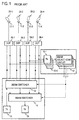
- a beam switcher 12 selectively connects a transmitter 13 to one of a plurality of antennas 11-1 to 11-4 having narrow beam angle directivities 35-1 to 35-4 in mutually different directions through respective duplexers 36-1 to 36-4 while a beam switcher 14 selectively connects a receiver 15 to one of the antennas, thus minimizing the number of transmission/reception network paths.
- receivers 16-1 to 16-4 are used to measure the signal strength from respective narrow beam antenna 11-1 to 11-4 to allow a beam selection control circuit 17 to switchably control the beam switchers 12, 14 so that transmitter 13 and the receiver 15 may be connected to one of the antennas having the maximum received signal power.
- a high resolution signal processing technique such as MUSIC is known in the art to estimate the arriving direction of a radiowave (DOA; Direction of Arrival), but requires a complex treatment including the calculation of a correlation matrix, resulting in a tremendous length of time as the number of antennas increases.
- DOA Direction of Arrival
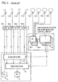
- the treatment of this technique is even more complicated when plural antenna having different directivities are used. For this reason, it necessitates the provision of an array antenna including antenna elements 18-1 to 18-4 having a common directivity for direction finding purpose, separately from communication antennas, as shown in Fig. 2.
- Received signals from the antenna elements 18-1 to 18-4 are fed to the receivers 16-1 to 16-4, outputs of which are processed in a circuit 19 according to the MUSIC procedure to determine the direction on which the transmitting mobile station is located, thus controlling the beam switchers 12 and 14.
- the mobile communication base station equipment premises that every user (mobile station) be serviced during a rapid movement thereof, it uses antenna which exhibit a common wide angle directivity response for a plurality of frequency channels and time slots.
- the base station equipment is radiating radio waves in directions of its service area such as a sector area, for example, other than the direction on which the user is located, and this represents a wasteful power dissipation.
- a conventional arrangement of base station equipment is shown in Fig. 3.
- a receiving antenna 111 and a transmitting /receiving antenna 112 are oriented in a common direction and have directivity responses indicated by principal beams 161 and 162, respectively, which are 120° wide.
- the receiving antenna 111 is directly connected to a combiner and distributor 26 while the transmitting/receiving antenna 112 is connected thereto through a duplexer 36.
- Each transmitter 13 of transmitter/receiver assemblies 115-1 to 115-L for frequency channels f1s to f1L inclusive of control channels and communication channels is connected to the transmit port of the combiner and distributor 26 while receivers 15-1 and 15-2 are connected to the respective receive port of the combiner and distributor 26 for the antennas 111 and 112, thus allowing the transmission and the reception of the control channel and the communication channel.
- Communication channel transmitter/receiver assemblies 121-1 to 121-M for frequency channels f21 to f2M each include a transmitter 122 which is connected to the transmit port of the combiner and distributor 26 and also each include receivers 123 and 124 which are connected to the respective receive port of the combiner and distributor 26 for the antennas 111 and 112, thus allowing the transmission and the reception of the communication channels.
- Each of the receivers 15-1 and 15-2 is adapted to diversity reception as is each of the receivers 123 and 124.
- Time slots which are utilized by the transmitter/receiver assemblies 115-1 to 115-L are shown in Fig. 4A and time slots which are utilized by the transmitter/receiver assemblies 121-1 to 121-M are shown in Fig. 4B.
- the beam 162 of the antenna which is used in each transmission has a width of 120°, and this means that a common beam is used for every frequency channel and time slot.
- a base station controller 126 allocates a channel which is used by either one of the transmitter/receiver assemblies 115-1 to 115-L and 121-1 to 121-M during a particular time slot.
- the arrangement which employs the direction finding of the mobile station and a result of such scan is used in switching a transmit/receive beam suffers from the accuracy of directional finding, the scale of equipment and the quantity of calculations.
- a wide angle beam antenna is fixedly assigned to every channel in a conventional base station equioment, this means that the equipment dissipates a wasteful radiation power in directions in its service area (such as a sector, for example) other than the direction on which a desired mobile station is located, contributing to increasing the quantity of interferences with other base stations. It is an object of the invention to provide a mobile communication base station equipment which enables a communication with a mobile station with a narrow angle beam by performing a direction finding of an arriving radio wave at a higher accuracy with a minimum scale of equipment and with a minimum volume of calculations.
- a pair of wide angle beam antennas located close to each other for substantially covering a service area which is covered by an entire assembly including a plurality of narrow angle beams.
- One of the antennas of the pair is connected to a communication receiver while the other antenna is connected to a direction finder receiver.
- the direction on which a mobile station transmitting a particular received radio wave is located is determined on the basis of phases of received signals from the both receivers.
- the function of the wide angle beam antenna may be served by one of the plurality of antennas which are used to form the narrow angle beams.
- a single wide angle beam antenna and a plurality of narrow angle beam antennas which collectively cover a service area of the wide angle beam antenna.
- a traveling speed of a mobile station and the direction of a narrow angle beam on which the mobile station is located are detected.
- one of communication channel transmitters/receivers capable of feeding transmitting power is allocated to the wide angle beam antenna while when the traveling speed is low, one of the communication channel transmitters/receivers capable of feeding transmitting power is allocated to the narrow angle beam antenna corresponding to the direction on which the mobile station is located.
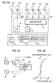
- Fig. 5A shows an embodiment according to the first aspect of the present invention, and corresponding parts to those shown in Fig. 1 are designated by like reference characters as used in Fig. 1, it being understood that throughout the description to follow, a similar convention is followed.
- a pair of antennas 21-1 and 21-2 which exhibit a wide angle directivity response (or wide angle beam).
- Each of the wide angle beam antennas 21-1 and 21-2 is capable of substantially covering a service area which is collectively covered by narrow angle beam antennas 11-1 to 11-4.
- both antennas 21-1 and 21-2 are located close to each other so as to be within the order of one-half the wavelength ( ⁇ ) of radio waves involved, and have wide angle beams 20-1 and 20-2 having central axes which are parallel to each other.
- a direction finder receiver 22 is connected to one of the wide angle beam antennas, 21-1, while a communication receiver 15 is connected to the other wide angle beam antenna 21-2.
- a received signal form the communication receiver 15 and a received signal from the direction finder receiver 22 are input to a direction measuring unit 23, which determines the direction of a mobile station transmitting the radio wave of the received signal on the basis of a phase difference between the both received signals.
- Channel information, synchronization information or a channel estimation information which is received by the communication receiver 15 is received under the same terms and conditions as the direction finder receiver 22. Since the wide angle beam antennas 21-1 and 21-2 are located close to each other, it follows that the correlation between the received signals from the wide angle beam antennas 21-1 and 21-2 is close to 1. Accordingly, by detecting the phase difference between the both received signals and adjusting the phase so that these signals cancel each other, namely choosing these signals to be of opposite phases, it is possible to estimate the arriving direction on the basis of the phase difference alone since the correlation between the signals is substantially equal to 1 with a minimal amplitude difference. By way of example, as illustrated in Fig.
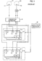
- the received signal from one of the receivers, 15, is fed to a variable phase shifter 201, the output of which is added with the output signal from the other receiver 22 in a combiner circuit 202.
- a phase shift which occurs in the variable phase shifter 201 is controlled in accordance with an output from the combiner circuit 202 so that the combiner circuit 202 delivers a zero output. It is to be understood that the both inputs to the combiner circuit 202 are pre-processed to an equal amplitude.
- the combiner circuit 202 when the both inputs to the combiner circuit 202 are of opposite phases to each other, it provides an output of zero, and a phase shift which prevails in the variable phase shifter 201 represents a phase difference ⁇ between the both received signals, which is then delivered to the beam selection control circuit 24.
- the phase difference (or phase shift) ⁇ has a one-to-one correspondence with respect to the arriving angle, as shown in Fig. 5B.
- the phase difference (or phase shift) ⁇ is equal to ⁇
- the arriving direction of the radio wave forms an angle of 0 with respect to a perpendicular or a bisector of a line joining the antennas 21-1 and 21-2.
- the phase difference (or adjusted phase shift) ⁇ becomes less than ⁇ , the arriving direction shifts to the left from the perpendicular, and conversely as the phase difference (or adjusted phase shift) ⁇ becomes greater than ⁇ , the arriving direction shifts to the right from the perpendicular.
- the beam switcher 12 is operated to connect the transmitter 13 to the antenna 11-i having the narrow angle beam 35-i which corresponds to the arriving direction which has been estimated by the phase difference (or adjusted phase shift) ⁇ .
- the transmitting beam 35-i of the base station equipment can be made to track the direction of the mobile station as it travels. It should be noted that the arriving direction of the radio wave can be detected merely by determining the phase difference (or adjusting the phase shift) without resort to adaptive signal processing and/or inverse matrix calculation.
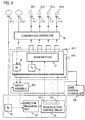
- Fig. 6 an arrangement as shown in Fig. 6 is used where parts corresponding to those shown in Fig. 5A are designated by like reference characters as used before. What differs from the arrangement of Fig. 5A is only the addition of a plurality of transmitters/receivers 25-1 to 25-L each including a beam switcher 12, a transmitter 13 and a receiver 15, a combiner and distributor 26 and a switch assembly 203. Outputs corresponding to respective narrow angle beams of the beam switchers 12 of the transmitters/receivers 25-1 to 25-L are combined together in the combiner and distributor 26 to be fed to corresponding ones of the narrow angled antennas 11-1 to 11-4.
- a plurality of transmitters/receivers 25-1 to 25-L each including a beam switcher 12, a transmitter 13 and a receiver 15, a combiner and distributor 26 and a switch assembly 203.
- Outputs corresponding to respective narrow angle beams of the beam switchers 12 of the transmitters/receivers 25-1 to 25-L are
- a received signal from a wide angle antenna 21-2 is distributed by the combiner and distributor 26 to be fed to respective communication receivers 15 of the transmitters/receivers 25-1 to 25-L.
- the channel allocation which determines which channels are used by the respective transmitters/receivers 25-1 to 25-L for purpose of communication is controlled by a base station controller 126.
- the base station controller 126 repeats sequentially establishing the channel which is allocated to one of the transmitters/receivers 25-1 to 25-L in the direction finder receiver 22, and each time the channel is established therein, it derives the received signal from the communication receiver 15 of one of the transmitters/receivers 25-1 to 25-L for which this channel has been allocated by controlling the switch assembly 203 to be fed to the direction measuring unit 23.
- the beam selection control circuit 24 includes output parts 53-1 to 53-L in a manner corresponding to the respective transmitters/receivers 25-1 to 25-L.
- a result of measurement of the direction on which a mobile station with which each of the transmitters/receivers 25-1 to 25-L is in communication is located is stored in the output parts 53-1 to 53-L, and the measured direction which is stored in the output parts 53-1 to 53-L is fed to the beam switcher 12 of the respective transmitter/receiver 25-1 to 25-L.
- the direction finder receiver 22 is arranged to operate in arbitrary channel in a time division manner, and the phase difference ⁇ of its received signal with respect to the corresponding receiver 15 in one of the transmitters/receivers 25-1 to 25-L is determined in the direction measuring unit 23, thus estimating the arriving direction of the received radio wave.
- the beam selection control circuit 24 controls the beam switcher 12 in one of the transmitters/receivers 25-1 to 25-L for which the channel has been established, thus selecting the narrow angle beam for purpose of transmission. In this manner, as a mobile station which is in communication with one of the transmitters/receivers 25-1 to 25-L travels, the transmitted beam may be made to track the direction of that mobile station.
- the embodiments shown in Figs. 5A and 6 represent an arrangement in which the narrow angle antennas 11-1 to 11-4 form the narrow angle beam forming antenna assembly 205 and the wide angle antennas 21-2 form the wide angle beam forming antennas 26.
- a multi-beam antenna 33 is formed by an array antenna 31 including wide angle beam antenna elements 31-1 to 31-4 and a beam former 32 which may comprise Butler matrix, for example.
- the antenna elements 31-1 to 31-4 are arrayed at a spacing on the order of one-half the wavelength ( ⁇ ) of the radio wave involved and each exhibit a wide angle directivity response (as indicated by a wide angle beam) 34 shown in broken lines in Fig. 7A.
- the multi-beam antenna 33 has a plurality of narrow angle directivity responses (narrow angle beams) 35-1 to 35-4 which are directed in mutually different directions.
- the service area of the wide angle beam 34 can be substantially covered by the narrow angle beams 35-1 to 35-4 collectively.
- a switched output from the beam switcher 12 can be fed through duplexers 36-1 to 36-4, respectively, to any one of the four ports of the beam former 32.
- each input forms a transmitted wave as represented by one of the narrow angle beams 35-1 to 35-4.
- the output from the duplexer 36-1 forms the transmitted wave corresponding to the narrow angle beam 35-1, for example.
- a received output from the multi-beam antenna 33 (corresponding to a signal from the input port during the transmission) is fed through the duplexers 36-1 to 36-4 to a beam former 37 which may comprise Butler matrix, for example, to be converted back to the received signal according to the directivity response of the wide angle beam antenna elements 31-1 and 31-2, for example, or corresponding to the wide angle beam 34.
- a beam former 37 which may comprise Butler matrix, for example, to be converted back to the received signal according to the directivity response of the wide angle beam antenna elements 31-1 and 31-2, for example, or corresponding to the wide angle beam 34.
- One of the received signals corresponding to the antenna elements 31-1 and 31-2 is fed to the communication receiver 15 while the other is fed to the direction finder receiver 22. It is to be noted that a coordination is made so that channel information, synchronization information and/or channel estimation information which is received by the communication receiver 15 is also received by the direction finder receiver 22 under the same terms and conditions.
- a spacing between the antenna elements 31-1 and 31-2 is on the order of one-half the wavelength or less, and accordingly, the arriving direction of the radio wave can be estimated by detecting the phase difference between the both received signals by the direction measuring unit 23, generally in the similar manner as described above in connection with Fig. 5A.
- an output from the transmitter 13 can be fed to the narrow angle beam which is oriented in this direction.
- a resulting arrangement will be as shown in Fig. 8, and what differs from Fig. 7A is the addition of a plurality of transmitters/receivers 25-1 to 25-L each including a beam switcher 12, a transmitter 13 and a receiver 15, a combiner and distributor 26, a distributor 26a and a switch assembly 203.
- Corresponding outputs from the respective beam switchers 12 are combined in the combiner and distributor 26 to be fed to corresponding ones of the duplexers 36-1 to 36-4.
- Outputs from the beam former 37 which are to be fed to the communication receivers 15 are distributed by the distributor 26a to the communication receivers 15 of the respective transmitters/receivers 25-1 to 25-L.
- the direction finder receiver 22 is arranged to operate in an arbitrary channel in a time division manner, and a phase difference between the received signal from the direction finder receiver 22 and the received signal from the communication receiver 15 for that channel is detected by a direction measuring unit 23, which selects and establishes a narrow angle beam to be used for the transmission from the transmitter 13 which forms a pair with this communication receiver 15.
- a direction measuring unit 23 which selects and establishes a narrow angle beam to be used for the transmission from the transmitter 13 which forms a pair with this communication receiver 15.
- the embodiment shown in Figs. 7 and 8 represent an arrangement in which the multi-beam antenna 33 comprises a narrow angle beam forming antenna assembly 205 while the combination of the multi-beam antenna 33 and the beam former 37 forms the wide angle beam forming antenna assembly 206.
- FIG. 9 A received signal which is input to the direction measuring unit 23 has a received power which undergoes a variation due to a fading effect or the like, as indicated by a curve 41 in Fig. 9A, for example.
- the determination of an i-th reliable measured direction ⁇ i will be described.
- a typical value is obtained as a mean power Ai of ai1 to aiM (Fig. 9A).
- an instantaneous phase difference between the both received signals is measured to obtain an instantaneous measured direction ⁇ i1 to ⁇ iM, and a typical value is obtained as a mean measured direction ⁇ i of ⁇ i1 to ⁇ iM (Fig. 9B).
- a mean power and a mean measured direction are obtained as A1, A2, ⁇ 1, ⁇ 2,... at the time interval of T.
- the reliable measured direction is the mean measured direction ⁇ 2 which is obtained at time t2 when the maximum mean power A2 is obtained among the three stored mean powers A1, A2 and A3 in the memory (it will be noted that the mean power A2 at time t2 is greater than the remaining values A1 and A3).
- This memory is sequentially updated by new data in a first-in and first-out (FIFO) manner.
- FIFO first-in and first-out
- the mean powers A2, A3 and A4 stored in the memory are compared against each other again, thus determining a new reliable direction according to the described algorithm (it will be seen that in Fig. 9, the reliable direction is determined to be ⁇ 2).
- the time interval T and the number of data N which is used in determining the maximum are chosen such that the correlation between the mean powers is minimized.
- ⁇ 5 is not selected as the reliable direction because the received mean power A5 is low.
- Fig. 9B shows the mean measured direction
- Fig. 9C shows the reliable direction determined and the direction in which the determination has occurred.
- the time interval T between successive measurements be determined to provide a reduced correlation between the mean powers obtained so that the fading structure can be recognized from N received mean powers and so that a comparison between the received powers in a depression zone is avoided. It will be seen that a longer time interval is preferred for T, but when a longer time interval is chosen, an updating of the measured direction is slowed down in a corresponding manner, degrading the tracking capability for a mobile station which travels rapidly. It is preferred that the time interval T be chosen in accordance with the traveling speed of the mobile station or the period of the fading effect.
- the number N of the mean powers which are used in detecting the maximum mean power is preferably chosen to avoid a depression zone in the received power and to enable the fading structure to be recognized from the mean powers being compared. For these reasons, the number of mean powers is chosen in a range from 3 to 10.
- the mean powers are measured a plurality of times (M-times) at the time interval of T in order to reduce the influence of noises, and should be made a plurality of times as close to each other as possible.
- the number M of measurements may be on the order of 10 to 20, for example.
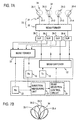
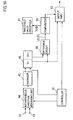
- Fig. 10 An exemplary functional arrangement which is used to determine the reliable direction is shown in Fig. 10.
- Both received signals which are input to a direction measuring unit 23 are applied to a pair of terminals 42 and 43 of an instantaneous direction measuring unit 44 where an instantaneous phase difference between the both received signals is measured a plurality of times (or M-times) to determine an instantaneous direction on the basis of the instantaneous phase difference.
- M values of the instantaneous measured direction are averaged in a direction averager 4, and a resulting mean direction is stored in a direction FIFO memory 46.
- the received signals applied to the terminals 42 and 43 are also input to an instantaneous power measuring unit 47 where the instantaneous power is measured M-times, and M values of the instantaneous power are averaged in a power averager 48, and a resulting mean power is stored in a power FIFO memory 49.
- the measurement of the instantaneous power may take place with respect to only one of the received signals applied to the terminals 42 and 43, or may take place with respect to a sum or a mean value thereof.
- a controller 51 operates the instantaneous direction measuring unit 44 and the instantaneous power measuring unit 47 at the time interval of T, and the outputs from the direction averager 45 and the power averager 48 are stored in the direction FIFO memory 46 and the power FIFO memory 49, respectively.
- the time of measurement when a maximum one of the mean powers which are stored in the power FIFO memory 49 is obtained is detected by a maximum power time detector 52, and the mean direction which prevails at this point in time is read out from the direction FIFO memory 46 to be delivered as the reliable direction from an output part 53, and as an output representing the measured direction determined by the direction measuring unit 23.
- Fig. 11 shows a processing procedure which takes place in the arrangement of Fig. 10.
- the instantaneous direction and the instantaneous power are measured (S1).
- the measurement is repeated until the measurement takes place a given number of times M (S2).
- a mean direction from M values of the instantaneous measured direction is calculated to be stored in the direction FIFO memory 46 (S3).
- a mean power of M values of the instantaneous measured power is calculated to be stored in the power FIFO memory 49 (S4).
- Fig. 12 Another principle of operation for obtaining a reliable measured direction will now be described with reference to Fig. 12.
- the determination of an i-th reliable measured direction ⁇ i will be described.
- the instantaneous received power is measured M times (which is equal to five times in Fig. 12) at the time interval of T to obtain values ai1 to aiM, and a typical value is obtained as a mean power Ai of ai1 to aiM (Fig. 12A).
- an instantaneous measured direction ⁇ i1 to ⁇ iM is measured from the phase difference between the both received signals, and a typical value is obtained as a mean measured direction ⁇ i of ⁇ i1 to ⁇ iM (Fig. 12).
- the mean value and the mean measured direction are obtained at the time interval of T in this manner. Assume that a mean power M3 is obtained at time t3, and if A3 is greater than a threshold value Th A , the mean measured direction ⁇ 3 which prevails at time t3 is determined to be a reliable measured direction and is used to update an output measured direction, while if A3 is less than the threshold value Th A , the measured direction is not updated.
- the time interval T and the threshold value Th A are suitably chosen, a measured direction which occurs during a depression in the received power where a large error in the measured direction is likely to occur cannot be selected as the reliable measured direction.
- the mean received power A5 which prevails at time t5 is less than the threshold value Th A , and thus, the mean measured direction ⁇ 5 cannot be adopted as the reliable measured direction. Instead, the direction measuring unit 23 delivers an output of ⁇ 4 at time t4, and does not deliver an output or again delivers ⁇ 4 at time t5. In the example shown in Fig. 12, only those mean directions shown in Fig. 12C are delivered as the reliable measured direction.
- FIG. 13 An exemplary functional arrangement for a direction measuring unit 23 which should operate to carry out the principle of operation mentioned above is shown in Fig. 13 where the parts corresponding to those shown in Fig. 10 are designated by like reference characters as used before.
- the instantaneous direction is measured by an instantaneous direction measuring unit 44 M times, and a mean direction is calculated by a direction averager 45.
- the instantaneous power is measured M times by an instantaneous power measuring unit 47, and a mean power is calculated in a power averager 48.
- the mean power is compared against a threshold value Th A fed from a threshold presetter 56 in a comparator 55.
- the mean direction delivered from the direction averager 45 is used to update the measured direction which is retained in an output part 53, whereby it is delivered as a reliable measured direction. If it is found in the comparator 55 that the mean power is less than the threshold value Th A , the measured direction retained in the output part 53 is not updated.
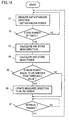
- FIG. 14 An exemplary processing procedure which is used for the arrangement shown in Fig. 13 is shown in Fig. 14.
- the instantaneous direction and the instantaneous power are measured a given number of times (M times) (S1 and S2).
- a mean direction for M values of the instantaneous direction and a mean power for M values of the instantaneous power are calculated (S3 and S4).
- An examination is made to see if the mean power is equal to or greater than the threshold value Th A (S5), and if the mean power is equal to or greater than Th A , the output measured direction is updated (S6) while if the mean power is less than Th A , the output measured direction is not updated, thus waiting for the time interval T to pass, whereupon the operation returns to step S1 (S7).
- Fig. 15 A further principle of operation for obtaining a reliable measured direction is illustrated in Fig. 15.
- the determination of an i-th reliable direction ⁇ i will be described.
- the instantaneous measured direction is measured M times (which is equal to five times in Fig. 15) at the time interval of T to obtain values ⁇ i1 to ⁇ iM, and a typical value is obtained as a mean measured direction ⁇ i of ⁇ i1 to ⁇ iM (Fig. 15B).
- a mean measured direction ⁇ 3 is obtained and is stored in a memory.
- the memory is sequentially updated in a first-in and first-out manner. For example, at time t4, the mean measured direction ⁇ 2 obtained at time t2 is discarded from a memory while a new mean measured direction ⁇ 4 is stored. At time t4, the difference between the two mean measured directions ⁇ 3 and ⁇ 4 in the memory is obtained, and the difference
- FIG. 16 An exemplary functional arrangement of this direction measuring unit 23 is shown in Fig. 16 where parts corresponding to those shown in Fig. 10 are designated by like reference characters as used before.
- An instantaneous direction is measured from the phase difference between the both received signals by an instantaneous direction measuring unit 44 M times at a time interval of T. Resulting M values of the instantaneous measured direction is averaged in an averager 45 to be stored in an FIFO memory 46.
- between the two mean measured directions contained in the FIFO memory 46 is calculated by a difference circuit 58, and the difference
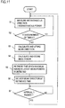
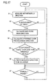
- FIG. 17 An exemplary processing procedure which is used with the arrangement shown in Fig. 16 is shown in Fig. 17.
- An instantaneous direction is measured on the basis of a phase difference between both received signals a given number of times (M times) (S1 and S2). M values of the instantaneous measured direction are averaged to be stored in a memory (S3).
- between the current and the previous mean measured value is calculated (S4), and an examination is made to see if
- Fig. 18 An additional functional arrangement for the direction measuring unit 23 which obtains a reliable measured direction is shown in Fig. 18 where parts corresponding to those shown in Fig. 16 are designated by like reference characters as used before.
- the instantaneous direction is measured M times by an instantaneous direction measuring unit 44 at time interval of T, and M values of the instantaneous measured direction are averaged in an averager 45 to be stored in a FIFO memory 46.
- the FIFO memory 46 stores four latest mean measured directions ⁇ i+1, ⁇ i, ⁇ i-1 and ⁇ i-2, for example, thus storing a time sequence of four latest values of the mean measured direction.
- Differences between each pair of adjacent mean measured directions in the time sequence are calculated by difference circuits 58 1 , 58 2 and 58 3 .
- One of the two mean measured directions which are used in forming the difference having the minimum value is chosen as a reliable measured direction, and thus is read out from the FIFO memory 46 to be delivered to an output part 53.
- from the difference circuit 58 2 is a minimum value
- ⁇ i-1 may also be delivered.
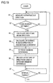
- FIG. 19 An exemplary processing procedure which is used with the arrangement shown in Fig. 18 is shown in Fig. 19.
- the instantaneous measured direction is measured M times (S1 and S2), and M values of the instantaneous direction is averaged to be stored in the FIFO memory 46 (S3). Differences (absolute values) between each pair of adjacent mean measured directions in the time sequence stored in the FIFO memory 46 are calculated (S4), and a minimum one of these differences is located.
- a latest one ⁇ i of the two mean measured directions ⁇ i and ⁇ i-1 which are used in reaching the difference of the minimum value is delivered as a measured direction (S6).
- the operation returns to step S1 after waiting for the time interval T to pass (S7).
- ⁇ i-1 may be delivered at step S6.
- the direction measuring unit 23 is designed to be controlled by a controller 51, as shown in Fig. 20, such that an instantaneous direction measuring unit 44 measures an instantaneous phase difference between both received signals to determine an instantaneous direction on the basis of such phase difference, the measurement of the instantaneous direction is preferably repeated a plurality of times and a mean value of the plurality of instantaneous directions is obtained in a direction averager 45.
- the instantaneous phase difference is measured a plurality of times and a mean value over these instantaneous phase differences is determined, and a mean direction may be determined on the basis of the mean phase difference.
- a reliability presence/absence decision unit 65 the presence or absence of the reliability in the mean direction is determined according to one of the techniques illustrated in Figs. 9 to 19, and the direction which has been determined to be reliable is delivered to an output part 53 as a measured direction.
- the instantaneous power of received signals has been measured, but alternatively, the instantaneous amplitude of the received signals may be measured.
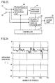
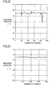
- Fig. 21 shows a result of experiments which determined a measured direction by the instantaneous direction measuring unit 44.
- the abscissa represents time in terms of the number of symbols, and the ordinate represents the measured direction.
- the actual arriving direction of the radio wave is equal to 45°.
- a result of experiments for the mean measured direction or the output from the direction averager 45 for the received signals which are under the same conditions as for Fig. 21 is as shown in Fig. 22. It will be seen from the results shown in Fig. 22 that a variation in the measured direction can be reduced by averaging values of the instantaneous measured direction. However, Fig. 22 shows that there still remains a large variation which cannot be suppressed even after the averaging operation. It is believed that this is due to a substantial reduction in the received power, namely during a deep depression in the received power or due to a depression caused by a fading effect when the arriving radio wave has an extended spatial reach.
- the measured direction which is retained in the output part 53 of direction measuring unit 23 is updated.
- information may be retained in the beam selection control circuit 24 and may be updated by an output from the output part 53.
- the direction measuring unit 23 may determine the arriving angle on the basis of an output level of a phase difference between those received signals which is detected by an analog phase difference detection circuit. It is necessary to invert the polarity of one of the both received signals in order to achieve the response as shown in Fig. 5B in this instance.
- a phase difference between both received signals can be determined by converting each received signal into a complex digital signal and determining the phase of each received signal to derive a difference therebetween.
- phase difference ⁇ is equal to 0 for the arriving angle of 0° in a direction of the perpendicular.
- the number of narrow angle beams is not limited to four, but any desired number of beams may be used.
- the function of the direction measuring unit 23 can be served by causing a computer to execute a program.
- one of received signals from a pair of received wide angle beams is fed to a communication receiver while the other is fed to a direction finder receiver.
- the arriving direction of the received radio wave is detected.
- the transmitting power can be reduced (due to a high gain of the antenna) and the interference can be reduced (due to the narrow angle beam).
- the arriving direction of the radio wave can be detected by simple means of detecting a phase difference.
- a single direction finder receiver is used for purpose of finding the arriving direction of a received radio wave while utilizing other communication receivers for the purpose of finding the direction.
- the entire arrangement is greatly simplified as compared with the prior art shown in Fig. 2.
- a single direction finder receiver can be used with transmitters/receivers for a plurality of communication channels.
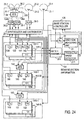
- Fig. 24 shows an embodiment according to a second aspect of the present invention.
- a pair of 60° beam (narrow angle beam) forming antenna assemblies 205 cover a 120°sector service area and a 120°beam (wide angle beam) antenna 21-2 covers the 120° sector service area while a combination of antennas 31-1 and 31-2 of the narrow angle beam forming antennas assembly 205 and the antennas 21-2 enables a diversity reception.
- the antennas 31-1 and 31-2 are connected through a hybrid 134 and through duplexers 36-1 and 36-2 to a combiner and distributor 26 while the 120° beam antennas 21-2 is connected through a duplexer 36-3 to the combiner and distributor 26.
- each of the principle beams 35-1 and 35-2 of the combined directivity response has a beam width of 60° and are directed to the left and to the right, respectively, while the antenna 21-2 has a wide angle beam 20-2 having a beam width of 120°, substantially covering the narrow angle beams 35-1 and 35-2.
- the combination of the antennas 31-1 and 31-2 and the hybrid 134 constitute the narrow angle beam forming assembly 205 which forms the pair of 60° beams (narrow angle beams) 35-1 and 35-2.
- Each of transmitters/receivers 137-1 to 137-L for channels f11 to f1L inclusive of control and communication channels includes a transmitter 138 which can feed transmitting power directly to the 120° beam (wide angle beam) antenna 21-2 through the combiner and distributor 26 and the duplexer 36-3, receivers 139 and 141, each of which can be fed with a received signal from each 60° beam port of the hybrid 134 through the combiner and distributor 26 and the duplexers 36-2 or 36-1, and a receiver 142 which can be fed with a received signal from the 120° beam antenna 21-2 through the combiner and distributor 26 and the duplexer 36-3.
- Each of the communication channel transmitters/receivers 143-1 to 143-L for channels f21 to f2M includes a receiver 144 which can feed a transmitting power to the 60° beam port 134a of the hybrid 134 through the combiner and distributor 26 and the duplexer 36-1, a receiver 145 which can be fed with a received signal from the both 60° beam ports 134a and 134b of the hybrid 134 through the hybrid 147, the combiner and distributor 26 and the duplexers 36-1 or 36-2, and a receiver 146 which can be fed with a received signal from the 120° beam antenna 21-2 through the combiner and distributor 26 and the duplexer 36-3.
- Each of communication channel transmitters/receivers 148-1 to 148-M for channels f31 to f3M includes a transmitter 149 which can feed transmitting power to the 60° beam port 134b of the hybrid 134 through the combiner and distributor 26 and the duplexer 36-2, a receiver 151 which can be fed with a received signal from either 60° beam port 134a or 134b of the hybrid 134 through the combiner and distributor 26 and the duplexer 36-1 or 36-2, and a receiver 152 which can be fed with a received signal from the 120° beam antenna 21-2 through the combiner and distributor 26 and the duplexer 36-3.
- Another wide angle beam antenna 21-1 which covers the service area in the similar manner as the wide angle beam antenna 21-2 is disposed close thereto within a distance of one-half the wavelength and is directed in the same beam direction.
- a received signal from the antenna 21-1 is received by a receiver 22.
- a received output from a control channel receiver 142 is fed to a beam selection information detection system 154, which obtains direction information ⁇ as both received signals from the receiver 142 and the receiver 22 are fed to a direction measuring unit 23 which is responsive thereto to determine whether the direction on which a mobile station, which provided the received signals, is located in the direction of the 60° beam 35-1 or in the direction of the 60° beam 35-2, and also obtains information Tf representing the traveling speed of the mobile station which is derived by a traveling speed detector 211 on the basis of a variation in the reception level of the receiver 142 or fading pitch Tf. It is to be noted that any one of various direction measuring units mentioned above can be used for the direction measuring unit 23 of this embodiment. As described above in connection with the embodiment of Fig.
- a base station controller 126 controls a switch assembly 203 so that the received signal from the receiver 142 of one of the transmitters/receivers 137-1 to 137-L be fed to the direction measuring unit 23 and the traveling speed detector 211, and also controls the receiver 22 to establish a channel therein.
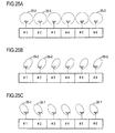
- the total time slots of the 120° beam control and communication channel transmitters/receivers 137-1 to 137-L are in the 120° beam (wide angle beam) 20-2, as shown in Fig. 25A.
- the time slots of the 60° beam communication channel transmitters/receivers 143-1 to 143-M are assigned to the right beam (narrow angle beam) 35-2 as shown in Fig. 25B while time slots of the 60° beam communication channel transmitters/receivers 148-1 to 148-N are assigned to the left beam (narrow angle beam) 35-1 as shown in Fig. 25C.
- the base station controller 126 interrogates the beam selection information detection system 154 for the traveling speed information (fading pitch Tf) and beam (direction) information ⁇ when it assigns a communication channel as during a call request or termination.
- the base station controller 126 operates in a manner shown in Fig. 26A. If Tf is greater than a given value, it is determined that a mobile station is in the course of rapidly traveling and thus one of the transmitters/receivers 137-1 to 137-L having a communication channel in the 120° beam (wide angle beam) is assigned for the intended communication (S2).
- step S1 if it is found at step S1 that Tf is less than the given value, it is determined that the mobile station remains stationary or is moving slowly, and a reference is made to the direction information ⁇ (S3) and one from either the transmitters/receivers 143-1 to 143-M or 148-1 to 148-N having a communication channel in the 60° beam (narrow angle beam) which includes the referred direction in its service area is assigned (S4). Because the transmitters/receivers 143-1 to 143-M or 148-1 to 148-N are assigned to a communication with a mobile station, for which the traveling speed is determined to be slow, the probability that a channel switching operation occurs during the communication with this mobile station is low.
- the beam selection information detection system 154 is not connected to the transmitters/receivers 143-1 to 143-M or 148-1 to 148-N. However, as indicated by broken lines in Fig. 26A, the beam selection information detection system 154 may be connected to the transmitters/receivers 143-1 to 143-M and 148-1 to 148-N so that subsequent to the completion of the steps S2 and S4, the operation may return to step S 1 where the traveling speed may be detected to switch between a wide angle beam transmitter/receiver and a narrow angle beam transmitter/receiver in an adaptive manner.
- the transmitting beam comprises a 120° beam and a pair of 60° beams, but it is also possible to use a 120° beam and a pair of 60° beams for the receiving beam in the similar manner as for the transmitting beam. It will be noted that in Fig. 24, the hybrids 147 and 153 are used to form a 120° beam for reception.
- the transmitters/receivers 143-1 to 143-M and 148-1 to 148-N which use 60° beam are capable of transmitting with a high gain antenna, and accordingly use a transmitting power which is 3 dB lower than the transmitting power used with the 120° beam transmitters/receivers 137-1 to 137-L.
- the transmitting power can be reduced by increasing the layers used such as a coverage of the service area by the 120° beam (layer 1), a coverage of the service area by the pair of 60° beams and a coverage of the service area by narrower beams such as four 30° beams (layer 3).
- the transmitting power may choose 0 dB for the layer 1, -3 dB for the layer 2 and -6 dB for the layer 3.
- one of 60° communication channel transmitters/receivers shown in Fig. 24, namely, 148-1 to 148-N, may be omitted and the transmitter 144 of the remaining 60° communication channel transmitters/receivers 143-1 to 143-M may feed a transmitting power to the 60° beam ports 134a and 134b in a switched manner.
- Such an arrangement is shown in Fig. 27.
- Each transmitter 144 can be switchably connected to the 60° beam ports 134a and 134b through a switch 158 and through the combiner and distributor 26.
- the total time slots of 120° beam control and communication channel transmitters/receivers 137-1 to 137-L are in the 120° beam 20-2, as shown in Fig. 28A while the time slots of the 60° communication channel transmitters/receivers 143-1 to 143-M are assigned to the left beam 35-1 for the first three slots and assigned to the right beam 35-2 for the second three slots, as shown in Fig. 28B. Its operation will be described below.
- a base station controller 126 interrogates a beam selection information detection system 154 for the traveling speed information (fading pitch Tf) and the direction information ⁇ when assigning a communication channel as during a call request or termination. In response to such information, if Tf is greater than the given value, the base station controller 126 determines that a mobile station is rapidly traveling, and accordingly, assigns one of the transmitters/receivers 137-1 to 137-L having a communication channel in the 120° beam. On the other hand, if Tf is less than the given value, the controller determines that the mobile station remains stationary or slowly traveling, and thus assigns one of the transmitters/receivers 143-1 to 143-M having a 60° beam communication channel.
- Tf traveling speed information
- ⁇ direction information
- the direction on which the mobile station is located is detected on the basis of a phase difference between received signals from the receiver 142 and the antenna 21-1, and a selection of either the right beam 35-2 or the left beam 35-1 is determined in accordance with such ⁇ information, and a corresponding time slot is assigned to this communication.
- the base station controller 126 switches a beam changing switch 158 in synchronism with the beam switching timing of the time slot.
- the transmitters/receivers 143-1 to 143-M are assigned only to a mobile station which has been determined to be traveling with a slow speed, the possibility that a channel switching operation occurs during the communication is low, and thus, the beam selection information detection system 154 is not connected to the transmitters/receivers 143-1 to 143-M.
- any one of the arrangements described above with reference to Figs. 5B and 9 to 20 may be used as the direction measuring unit 23 used within the beam selection information detection system 154 shown in Fig. 24.
- the antenna 21-1 and the receiver 22 may be omitted, and a level comparator 213 shown in Fig. 29 may be used in place of the direction measuring unit 23 in the beam selection information detection system 154, thus determining the narrow angle beam which is directed on the direction on which a mobile station transmitting the received radio wave is located.
- Received signals from the receivers 139, 141 and 142 in the 120° beam control and communication channel transmitters/receivers 137-1 to 137-L are fed to the beam selection information detection system 154 including a switch assembly 203 where the received signal from the receivers 139, 141 and 142 of one of the transmitters/receivers 137-1 to 137-L are selected.
- Received signals from the receivers 139 and 141 are fed to the level comparator 213 where the levels of the both received signals are compared against each other. If the received signal level of the receiver 139 is greater than the received signal level from the receiver 141, it is determined that the mobile station is located in the service area of the narrow angle beam 35-2. On the contrary, if the received signal level from the receiver 141 is higher, it is determined that the mobile station is located in the service area of the narrow angle beam 35-1. Beam (direction) information indicating the narrow angle beam thus determined is delivered.
- the base station controller 126 assigns one of the communication channel transmitters/receivers including a communication channel transmitter which feeds a transmitting power to the narrow angle beam which has been determined by the level comparator 213.
- the beam information indicated by the beam selection information detection system 154 indicates the narrow angle beam 35-1
- one of the communication transmitters/receivers 143-1 to 143-M is assigned
- the beam information indicates the narrow angle beam 35-2
- one of the communication transmitters 148-1 to 148-N is assigned.
- the beam selection information detection system 154 shown in Fig. 29 is used in the embodiment of Fig.
- the base station controller 126 assigns one of the communication channel transmitters/receivers 143-1 to 143-M if the traveling speed is equal to or less than a given value, and assigns a time slot to the communication which is chosen in accordance with the relationship between the time slot and the narrow angle beam shown in Fig. 28B depending on the beam information from the level comparator 213, namely, whether it indicates the right beam 35-2 or the left beam 35-1.
- Fig. 30 One embodiment which uses the beam selection information detection system 154 shown in Fig. 29, but in which the diversity arrangement is removed from the arrangement shown in Fig. 24 is shown in Fig. 30 where corresponding parts to those described before are designated by like reference characters. Specifically, in this embodiment, the 120° beam antennas 21-1 and 21-2, the duplexer 36-3 and the receivers 22, 142, 146 and 152 are omitted from the arrangement of Fig. 24.
- Each transmitter 38 in the 120° beam control and communication channel transmitters/receivers 137-1 to 137-L is capable of feeding a transmitting power to the both 60° beam ports 134a and 134b of the hybrid 134 through a hybrid 156, and through the combiner and distributor 26 and the duplexers 36-1 and 36-2, thus feeding transmitting power to the 120° beam (wide angle beam) antenna assembly 215.
- a plurality of narrow angle beam antennas 31-1 and 31-2 may be used to perform the transmission and the reception through a single wide angle beam.
- the 120° beam antenna 21-1 and 21-2 may be omitted, and the beam selection information detection system 154 shown in Fig. 29 may be used to cause the pair of 60° beam antenna 31-1 and 31-2 to serve as the 120° beam antennas, in the similar manner as shown in Fig. 30.
- the wide angle beam is not limited to 120° as described above, but may cover 360°, for example. Instead of covering a service area which is covered by a wide angle beam by a pair of narrow angle beams, three or more narrow angle beams may be used to cover the service area of the wide angle beam.
- a narrow angle beam can be assigned to a mobile station which is traveling slowly, without irradiating unnecessary radio waves in directions other than the direction on which a desired mobile station is located.
- the transmitting power from the base station equipment can be reduced in a corresponding manner, and the interferences can also be reduced because a dispersion of radio waves can be suppressed.
Landscapes
- Engineering & Computer Science (AREA)
- Computer Networks & Wireless Communication (AREA)
- Signal Processing (AREA)
- Mobile Radio Communication Systems (AREA)
- Radio Transmission System (AREA)
Abstract
Description
Claims (17)
- A mobile communication base station equipment comprisinga wide angle beam forming antenna assembly which forms a pair of wide angle beams located close to each other and directed in a common direction;a narrow angle beam forming antenna assembly for forming a plurality of narrow angle beams having directivity responses which are directed in different directions and collectively covering the wide angle beam;a communication transmitter;a beam switcher connected between the communication transmitter and the narrow angle beam antenna assembly for selectively feeding transmitting power from the communication transmitter to the plurality of narrow angle beams;a communication receiver connected to the wide angle beam forming antenna assembly and fed with a received signal from one of the pair of wide angle beams formed by the wide angle beam forming antenna assembly;a direction finder receiver connected to the wide angle beam forming antenna assembly and fed with a received signal from the other wide angle beam of the pair from the wide angle beam forming assembly;a direction measuring unit for measuring a direction on which a mobile station transmitting the received signal is located from a phase difference between the both received signals from the communication receiver and the direction finder receiver;and a beam selection control circuit connected to the direction measuring unit and the beam switcher for controlling the beam switcher by feeding an output from the transmitter to one of the plurality of narrow angle beams in accordance with the measured direction.
- A mobile communication base station equipment according to Claim 1 in which there are provided N sets (where N is an integer equal to or greater than 2) of said beam switcher, said communication transmitter and said communication receivers, further comprisinga combiner and distributor for combining outputs from the communication transmitters which are fed from said N beam switchers in a manner corresponding to each of the narrow angle beams and for distributing the received signals which are to be fed from the wide angle beam forming antenna assembly to the communication receivers among said N communication receivers;and a switch assembly for feeding the received signals from said N communication receivers to the direction measuring unit in a time division manner;said beam selection control circuit being operative to control one of the beam switchers which forms a pair with the communication receiver which is used to determine the measured direction.
- A mobile communication base station equipment according to Claim 1 or 2 in which the narrow angle beam forming antenna assembly comprises a plurality of narrow angle beam antennae each forming a narrow angle beam, and the wide angle beam forming antenna assembly comprises a pair of wide angle beam antenna each forming said wide angle beam.
- A mobile communication base station equipment according to Claim 1 or 2 in which the narrow angle beam forming antenna assembly comprises a multi-beam antenna including an array antenna having a spacing on the order of one-half the wavelength and a beam former to define the plurality of narrow angle beams, and the wide angle beam forming antenna assembly comprises the multi-beam antenna, and a beam demultiplexer which demultiplexes a signal received by the multi-beam antenna in the plurality of narrow angle beams into two received signals, each of which has the directivity response of each of two elements in the array antenna..
- A mobile communication base station equipment according to any one of Claims 1-4 in which the direction measuring unit comprises a direction measuring assembly for measuring a phase difference between the both received signals to measure a direction, a reliability presence/absence decision unit for determining the presence or absence of a reliability in the measured direction, and an output part for delivering the measured direction which has been determined to be reliable by the reliability presence/absence decision unit.
- A mobile communication base station equipment according to Claim 5 in which the reliability presence/absence decision unit comprises a magnitude measuring unit for measuring the magnitude of at least one of the both received signals, a memory for storing the measured direction and the measured magnitude, and a maximum value detector for detecting a maximum one of a plurality of latest values of the measured magnitude to determine that the measured direction which is obtained when the detected maximum magnitude is measured as reliable.
- A mobile communication base station equipment according to Claim 5 in which the reliability presence/absence decision unit comprises a magnitude measuring unit for measuring the magnitude of at least one of the received signals, and a comparator for determining whether or not the measured magnitude exceeds a threshold value and in the event the measured magnitude is determined to have exceeded the threshold value, determining the measured direction as reliable.
- A mobile communication base station equipment according to Claim 5 in which the reliability presence/absence decision unit comprises a difference circuit for determining a difference between a current measured direction and a previous measured direction, and a comparator for determining whether or not the difference has exceeded a threshold value and in the event it is determined that the difference is equal to or less than the threshold value, determining the current measured direction as reliable.
- A mobile communication base station equipment according to Claim 5 in which the reliability presence/absence decision circuit comprises a memory for storing the measured direction, a difference circuit for determining a difference between adjacent measured directions in a time sequence of measured directions stored in the memory inclusive of a latest measured direction, and a minimum value detector for detecting a minimum one of the differences and determining one of the two measured directions which are used in detecting the minimum difference as reliable.
- A mobile communication base station equipment according to any one of Claims 5-9 in which the direction measuring unit comprises a measuring unit for measuring an instantaneous phase difference between both concurrent received signals a plurality of times, and an averager for determining a mean measured direction corresponding to the plurality of values of the instantaneous phase difference and providing it as the measured direction.
- A mobile communication base station equipment according to Claim 6 or 7 in which the magnitude measuring unit comprises an instantaneous magnitude measuring unit for measuring an instantaneous magnitude of concurrent received signals a plurality of times, and an averager for averaging the plurality of values of the instantaneous magnitude to provide the measured magnitude.
- A mobile communication base station equipment comprisinga wide angle beam forming antenna assembly for forming a wide angle beam;a narrow angle beam forming antenna assembly for forming a plurality of narrow angle beams having directivity responses which are directed in different directions and collectively covering the wide angle beam;a plurality of wide angle beam communication channel transmitters/receivers capable of feeding the wide angle beam forming antenna assembly;a plurality of narrow angle beam communication channel transmitters/receivers capable of feeding each narrow angle beam of the narrow angle beam forming antenna assembly;a beam selection information detection system for detecting a traveling speed of a mobile station and for detecting which one of the narrow angle beams represents a direction on which the mobile station is located;and a base station controller for selectively assigning one from the wide angle beam communication channel transmitters/receivers or the narrow angle beam communication transmitters/receivers for a communication with the mobile station on the basis of the detected traveling speed and the detected direction of the mobile station.
- A mobile communication base station equipment according to Claim 12 in which the base station equipment is of a time division multiple access communication system, the base station controller including a switch assembly which switches the narrow angle beam of the narrow angle beam communication channel transmitters/receivers in accordance with a time slot of the time division communication system, the base station controller assigning a time slot which corresponds to the direction of the mobile station when assigning one of the narrow angle beam communication channel transmitters/receivers.
- A mobile communication base station equipment according to Claim 12 or 13, further comprisinga direction finder antenna for forming a wide angle beam of the same configuration as the first mentioned wide angle beam and oriented in the same direction and located close thereto;and a direction finder receiver connected to the direction finder antenna;the beam selection information detection system comprising a traveling speed detector which is fed with a received signal from the wide angle beam for detecting information representing a traveling speed of a mobile station which is transmitting the received signal, and a direction measuring unit which is fed with a received signal from the wide angle beam and a received signal from the direction finder receiver to measure the direction on which the mobile station is located from a phase difference between the both received signals.
- A mobile communication base station equipment according to Claim 14 in which the direction measuring unit comprises a reliability presence/absence decision unit for determining the presence or absence of a reliability in the measured direction and for delivering the measured direction which is determined to be reliable.
- A mobile communication base station equipment according to Claim 12 or 14 in which the beam selection information detection system comprises a traveling speed detector which is fed with a received signal from the wide angle beam for detecting information representing a traveling speed of a mobile station which is transmitting the received signal, and a level comparator which is fed with received signals from the plurality of narrow angle beams for determining a direction indicated by the directivity of the narrow angle beam which produced a maximum reception level as the direction on which the mobile station is located.
- A mobile communication base station equipment according to any one of Claims 12-16, further comprisinga combiner for forming the plurality of narrow angle beams into the wide angle beam, whereby the narrow angle beam forming antenna assembly also serves as the wide angle beam forming antenna assembly.
Applications Claiming Priority (6)
| Application Number | Priority Date | Filing Date | Title |
|---|---|---|---|
| JP2000301896A JP2002111556A (en) | 2000-10-02 | 2000-10-02 | Base station equipment |
| JP2000301895 | 2000-10-02 | ||
| JP2000301896 | 2000-10-02 | ||
| JP2000301895 | 2000-10-02 | ||
| JP2001052659 | 2001-02-27 | ||
| JP2001052659A JP2002185236A (en) | 2000-10-02 | 2001-02-27 | Antenna system |
Publications (3)
| Publication Number | Publication Date |
|---|---|
| EP1193792A2 true EP1193792A2 (en) | 2002-04-03 |
| EP1193792A3 EP1193792A3 (en) | 2003-06-04 |
| EP1193792B1 EP1193792B1 (en) | 2009-03-25 |
Family
ID=27344822
Family Applications (1)
| Application Number | Title | Priority Date | Filing Date |
|---|---|---|---|
| EP01123595A Expired - Lifetime EP1193792B1 (en) | 2000-10-02 | 2001-10-01 | Mobile communication base station equipment |
Country Status (8)
| Country | Link |
|---|---|
| US (1) | US6907269B2 (en) |
| EP (1) | EP1193792B1 (en) |
| KR (1) | KR100452536B1 (en) |
| CN (1) | CN100446594C (en) |
| AU (1) | AU756585B2 (en) |
| CA (1) | CA2358125C (en) |
| DE (1) | DE60138078D1 (en) |
| SG (1) | SG115412A1 (en) |
Cited By (4)
| Publication number | Priority date | Publication date | Assignee | Title |
|---|---|---|---|---|
| WO2004102739A1 (en) * | 2003-05-17 | 2004-11-25 | Quintel Technology Limited | Phased array antenna system with adjustable electrical tilt |
| EP1719262A4 (en) * | 2004-02-06 | 2009-03-18 | Interdigital Tech Corp | Method and apparatus for reducing transient impacts of beam switching in a switched beam antenna system |
| GB2459131A (en) * | 2008-04-11 | 2009-10-14 | Vodafone Group Services Ltd | Locating nodes of a telecommunications system |
| CN101566683B (en) * | 2009-03-24 | 2011-09-14 | 西北工业大学 | Method for estimating target azimuth formed based on phase difference beams |
Families Citing this family (90)
| Publication number | Priority date | Publication date | Assignee | Title |
|---|---|---|---|---|
| JP4187377B2 (en) * | 2000-02-23 | 2008-11-26 | 富士通株式会社 | Radio transceiver and radio wave radiation direction control method |
| WO2001091332A1 (en) * | 2000-05-26 | 2001-11-29 | Matsushita Electric Industrial Co., Ltd. | Base station apparatus and packet transmitting method |
| US7295509B2 (en) | 2000-09-13 | 2007-11-13 | Qualcomm, Incorporated | Signaling method in an OFDM multiple access system |
| US9130810B2 (en) | 2000-09-13 | 2015-09-08 | Qualcomm Incorporated | OFDM communications methods and apparatus |
| GB0224341D0 (en) * | 2002-10-19 | 2002-11-27 | Qinetiq Ltd | Mobile radio base station |
| TW595857U (en) * | 2001-11-29 | 2004-06-21 | Us | 091219345 |
| FI20020400A0 (en) * | 2002-03-01 | 2002-03-01 | Nokia Corp | Determining the direction of a signal in a radio system |
| US7751825B2 (en) | 2002-06-27 | 2010-07-06 | Qualcomm Incorporated | Controlling geographic location information of devices operating in wireless communication systems |
| US6785559B1 (en) | 2002-06-28 | 2004-08-31 | Interdigital Technology Corporation | System for efficiently covering a sectorized cell utilizing beam forming and sweeping |
| US7043274B2 (en) * | 2002-06-28 | 2006-05-09 | Interdigital Technology Corporation | System for efficiently providing coverage of a sectorized cell for common and dedicated channels utilizing beam forming and sweeping |
| US6768459B2 (en) | 2002-07-31 | 2004-07-27 | Interdigital Technology Corporation | Method and system for positioning mobile units based on angle measurements |
| JP4309110B2 (en) * | 2002-09-27 | 2009-08-05 | パナソニック株式会社 | Adaptive antenna wireless communication device |
| JP2004135177A (en) * | 2002-10-11 | 2004-04-30 | Sharp Corp | Mobile phone |
| AU2003286830A1 (en) | 2002-11-04 | 2004-06-07 | Vivato, Inc. | Forced beam switching in wireless communication systems having smart antennas |
| AU2003285138A1 (en) | 2002-11-04 | 2004-06-07 | Vivato Inc | Directed wireless communication |
| JP4186627B2 (en) * | 2003-01-22 | 2008-11-26 | 日本電気株式会社 | Reception directional antenna control apparatus, beam selection method used therefor, and program thereof |
| JP3909844B2 (en) * | 2003-01-30 | 2007-04-25 | 松下電器産業株式会社 | Wireless communication device |
| JP3933597B2 (en) * | 2003-03-27 | 2007-06-20 | 三洋電機株式会社 | Transmission method and wireless device using the same |
| US20050136910A1 (en) * | 2003-12-18 | 2005-06-23 | Qinghua Li | Multicast SDMA training polls |
| JP2007529160A (en) * | 2003-10-15 | 2007-10-18 | 松下電器産業株式会社 | Diversity receiving apparatus and radio receiving apparatus using the same |
| US8699508B2 (en) * | 2003-12-18 | 2014-04-15 | Intel Corporation | Response scheduling for multiple receivers |
| WO2005104142A1 (en) * | 2004-04-22 | 2005-11-03 | Brother Kogyo Kabushiki Kaisha | Radio tag communication device |
| US9137822B2 (en) | 2004-07-21 | 2015-09-15 | Qualcomm Incorporated | Efficient signaling over access channel |
| US9148256B2 (en) | 2004-07-21 | 2015-09-29 | Qualcomm Incorporated | Performance based rank prediction for MIMO design |
| JP4833534B2 (en) * | 2004-09-29 | 2011-12-07 | 富士通株式会社 | Radar equipment |
| WO2006077842A1 (en) * | 2005-01-19 | 2006-07-27 | Nec Corporation | Wireless communication apparatus, and antenna directivity/radio resource assigning method |
| US9246560B2 (en) | 2005-03-10 | 2016-01-26 | Qualcomm Incorporated | Systems and methods for beamforming and rate control in a multi-input multi-output communication systems |
| US8995547B2 (en) * | 2005-03-11 | 2015-03-31 | Qualcomm Incorporated | Systems and methods for reducing uplink resources to provide channel performance feedback for adjustment of downlink MIMO channel data rates |
| US9154211B2 (en) | 2005-03-11 | 2015-10-06 | Qualcomm Incorporated | Systems and methods for beamforming feedback in multi antenna communication systems |
| US8724740B2 (en) | 2005-03-11 | 2014-05-13 | Qualcomm Incorporated | Systems and methods for reducing uplink resources to provide channel performance feedback for adjustment of downlink MIMO channel data rates |
| US8446892B2 (en) | 2005-03-16 | 2013-05-21 | Qualcomm Incorporated | Channel structures for a quasi-orthogonal multiple-access communication system |
| US9520972B2 (en) | 2005-03-17 | 2016-12-13 | Qualcomm Incorporated | Pilot signal transmission for an orthogonal frequency division wireless communication system |
| US9143305B2 (en) | 2005-03-17 | 2015-09-22 | Qualcomm Incorporated | Pilot signal transmission for an orthogonal frequency division wireless communication system |
| US9461859B2 (en) | 2005-03-17 | 2016-10-04 | Qualcomm Incorporated | Pilot signal transmission for an orthogonal frequency division wireless communication system |
| US9184870B2 (en) | 2005-04-01 | 2015-11-10 | Qualcomm Incorporated | Systems and methods for control channel signaling |
| US9036538B2 (en) | 2005-04-19 | 2015-05-19 | Qualcomm Incorporated | Frequency hopping design for single carrier FDMA systems |
| US9408220B2 (en) | 2005-04-19 | 2016-08-02 | Qualcomm Incorporated | Channel quality reporting for adaptive sectorization |
| US8565194B2 (en) | 2005-10-27 | 2013-10-22 | Qualcomm Incorporated | Puncturing signaling channel for a wireless communication system |
| US8879511B2 (en) | 2005-10-27 | 2014-11-04 | Qualcomm Incorporated | Assignment acknowledgement for a wireless communication system |
| US8611284B2 (en) | 2005-05-31 | 2013-12-17 | Qualcomm Incorporated | Use of supplemental assignments to decrement resources |
| US8462859B2 (en) | 2005-06-01 | 2013-06-11 | Qualcomm Incorporated | Sphere decoding apparatus |
| US9179319B2 (en) | 2005-06-16 | 2015-11-03 | Qualcomm Incorporated | Adaptive sectorization in cellular systems |
| US8599945B2 (en) | 2005-06-16 | 2013-12-03 | Qualcomm Incorporated | Robust rank prediction for a MIMO system |
| US7353001B1 (en) * | 2005-07-07 | 2008-04-01 | Sprint Spectrum L.P. | Method and apparatus for managing beam selection in a mobile handset |
| US8885628B2 (en) | 2005-08-08 | 2014-11-11 | Qualcomm Incorporated | Code division multiplexing in a single-carrier frequency division multiple access system |
| US9209956B2 (en) | 2005-08-22 | 2015-12-08 | Qualcomm Incorporated | Segment sensitive scheduling |
| US20070041457A1 (en) | 2005-08-22 | 2007-02-22 | Tamer Kadous | Method and apparatus for providing antenna diversity in a wireless communication system |
| US8073068B2 (en) | 2005-08-22 | 2011-12-06 | Qualcomm Incorporated | Selective virtual antenna transmission |
| US8644292B2 (en) | 2005-08-24 | 2014-02-04 | Qualcomm Incorporated | Varied transmission time intervals for wireless communication system |
| US9136974B2 (en) | 2005-08-30 | 2015-09-15 | Qualcomm Incorporated | Precoding and SDMA support |
| US8045512B2 (en) | 2005-10-27 | 2011-10-25 | Qualcomm Incorporated | Scalable frequency band operation in wireless communication systems |
| US9225416B2 (en) | 2005-10-27 | 2015-12-29 | Qualcomm Incorporated | Varied signaling channels for a reverse link in a wireless communication system |
| US8477684B2 (en) | 2005-10-27 | 2013-07-02 | Qualcomm Incorporated | Acknowledgement of control messages in a wireless communication system |
| US9172453B2 (en) | 2005-10-27 | 2015-10-27 | Qualcomm Incorporated | Method and apparatus for pre-coding frequency division duplexing system |
| US9210651B2 (en) | 2005-10-27 | 2015-12-08 | Qualcomm Incorporated | Method and apparatus for bootstraping information in a communication system |
| US9088384B2 (en) | 2005-10-27 | 2015-07-21 | Qualcomm Incorporated | Pilot symbol transmission in wireless communication systems |
| US9144060B2 (en) | 2005-10-27 | 2015-09-22 | Qualcomm Incorporated | Resource allocation for shared signaling channels |
| US8693405B2 (en) | 2005-10-27 | 2014-04-08 | Qualcomm Incorporated | SDMA resource management |
| US8582509B2 (en) | 2005-10-27 | 2013-11-12 | Qualcomm Incorporated | Scalable frequency band operation in wireless communication systems |
| US9225488B2 (en) | 2005-10-27 | 2015-12-29 | Qualcomm Incorporated | Shared signaling channel |
| US8582548B2 (en) | 2005-11-18 | 2013-11-12 | Qualcomm Incorporated | Frequency division multiple access schemes for wireless communication |
| US8831607B2 (en) | 2006-01-05 | 2014-09-09 | Qualcomm Incorporated | Reverse link other sector communication |
| KR20090071582A (en) * | 2006-09-06 | 2009-07-01 | 콸콤 인코포레이티드 | Codeword Substitution and Reduced Feedback for Grouped Antennas |
| US8238832B1 (en) * | 2007-08-28 | 2012-08-07 | Marvell International Ltd. | Antenna optimum beam forming for multiple protocol coexistence on a wireless device |
| FR2921532B1 (en) * | 2007-09-21 | 2009-11-13 | Canon Kk | METHOD FOR SYNCHRONIZING A SYNCHRONIZED NODE IN A FIRST SYNCHRONOUS WIRELESS COMMUNICATION CHANNEL OF A COMMUNICATION NETWORK, COMPUTER PROGRAM PRODUCT, AND CORRESPONDING SYNCHRONIZING NODE |
| JP5109707B2 (en) * | 2008-02-19 | 2012-12-26 | コニカミノルタビジネステクノロジーズ株式会社 | Fixing apparatus and image forming apparatus |
| US8380531B2 (en) * | 2008-07-25 | 2013-02-19 | Invivodata, Inc. | Clinical trial endpoint development process |
| KR101053855B1 (en) * | 2009-01-22 | 2011-08-03 | 주식회사 만도 | Sensor vertical alignment regulator and sensor |
| US8344940B2 (en) * | 2009-01-22 | 2013-01-01 | Mando Corporation | Apparatus and sensor for adjusting sensor vertical alignment |
| GB2467770B (en) | 2009-02-13 | 2011-08-17 | Socowave Technologies Ltd | Communication system, apparatus and method for antenna array control |
| JP5381150B2 (en) * | 2009-02-23 | 2014-01-08 | パナソニック株式会社 | Diversity antenna device and electronic device using the same |
| FR2968865A1 (en) * | 2010-12-08 | 2012-06-15 | Thomson Licensing | DEVICE FOR RECEIVING OR TRANSMITTING / RECEIVING MIMO SIGNALS |
| JP2013096908A (en) * | 2011-11-02 | 2013-05-20 | Honda Elesys Co Ltd | Radar apparatus for on-vehicle use, method for on-vehicle radar operation, and program for on-vehicle radar operation |
| US9160435B2 (en) | 2011-12-13 | 2015-10-13 | Intel Corporation | Beamforming based on information from platform sensors |
| WO2013089681A1 (en) | 2011-12-13 | 2013-06-20 | Intel Corporation | Link prediction based re-beamforming triggering algorithm for 60 ghz communication links |
| US9633247B2 (en) * | 2012-03-01 | 2017-04-25 | Apple Inc. | Electronic device with shared near field communications and sensor structures |
| JP2014002053A (en) | 2012-06-19 | 2014-01-09 | Honda Elesys Co Ltd | On-vehicle rader system, on-vehicle radar method and on-vehicle radar program |
| CA2875701C (en) * | 2012-06-21 | 2016-08-23 | Cable Television Laboratories, Inc. | Efficient adaptable wireless network system with agile beamforming |
| CN103888195A (en) * | 2012-12-19 | 2014-06-25 | 北京信威通信技术股份有限公司 | Method for fixedly erecting terminal directional antenna |
| KR102118615B1 (en) * | 2014-02-12 | 2020-06-03 | 삼성전자주식회사 | Method and apparatus for communication |
| US9398468B1 (en) | 2014-12-29 | 2016-07-19 | Huawei Technologies Co., Ltd. | Cellular array with steerable spotlight beams |
| WO2016106620A1 (en) * | 2014-12-31 | 2016-07-07 | 华为技术有限公司 | Antenna alignment method and system |
| US20160192209A1 (en) * | 2014-12-31 | 2016-06-30 | Thomson Licensing | Antenna radiation pattern adjustment and mobile devices |
| EP3273717A4 (en) * | 2015-03-16 | 2018-11-14 | NTT DoCoMo, Inc. | User device, base station, and communication method |
| JP2018133733A (en) * | 2017-02-16 | 2018-08-23 | 株式会社フジクラ | Radio communication system and radio communication method |
| EP3591856B1 (en) * | 2018-07-04 | 2021-10-27 | Intel Corporation | Techniques for control of beam switching |
| KR102534720B1 (en) * | 2018-10-11 | 2023-05-22 | 삼성전자주식회사 | A method and an electronic device detecting radio frequency signal |
| CN109638476B (en) * | 2018-12-29 | 2021-01-15 | 华南理工大学 | Feeder network and dual beam antenna |
| US10998945B1 (en) * | 2020-01-10 | 2021-05-04 | Huawei Technologies Co., Ltd. | Beam acquisition methods and communication devices |
| WO2025124685A1 (en) * | 2023-12-11 | 2025-06-19 | Telefonaktiebolaget Lm Ericsson (Publ) | Low power millimeter wave (mmwave) receiver for beam tracking |
Family Cites Families (13)
| Publication number | Priority date | Publication date | Assignee | Title |
|---|---|---|---|---|
| US4317229A (en) | 1977-05-02 | 1982-02-23 | Motorola, Inc. | Sectored antenna receiving system |
| TW351886B (en) * | 1993-09-27 | 1999-02-01 | Ericsson Telefon Ab L M | Using two classes of channels with different capacity |
| US5596333A (en) * | 1994-08-31 | 1997-01-21 | Motorola, Inc. | Method and apparatus for conveying a communication signal between a communication unit and a base site |
| US5684491A (en) * | 1995-01-27 | 1997-11-04 | Hazeltine Corporation | High gain antenna systems for cellular use |
| JPH09284200A (en) | 1996-04-10 | 1997-10-31 | Mitsubishi Electric Corp | Wireless communication device and wireless communication method |
| JP3204111B2 (en) * | 1996-08-28 | 2001-09-04 | 松下電器産業株式会社 | Directivity control antenna device |
| GB2320618A (en) * | 1996-12-20 | 1998-06-24 | Northern Telecom Ltd | Base station antenna arrangement with narrow overlapping beams |
| WO1998042150A2 (en) * | 1997-03-14 | 1998-09-24 | At & T Corp. | Downlink smart antennas for is-54/is-136 tdma systems |
| SE509278C2 (en) * | 1997-05-07 | 1999-01-11 | Ericsson Telefon Ab L M | Radio antenna device and method for simultaneous generation of wide lobe and narrow point lobe |
| JP3332329B2 (en) * | 1997-06-02 | 2002-10-07 | 株式会社エヌ・ティ・ティ・ドコモ | Adaptive array antenna device |
| KR100292040B1 (en) * | 1997-07-05 | 2001-07-12 | 최승원 | Beam selection methods of multi-beam array antenna and transceivers using them |
| JP3233088B2 (en) * | 1998-01-22 | 2001-11-26 | 松下電器産業株式会社 | Directivity control antenna device |
| US20010016504A1 (en) * | 1998-04-03 | 2001-08-23 | Henrik Dam | Method and system for handling radio signals in a radio base station |
-
2001
- 2001-09-29 KR KR10-2001-0060954A patent/KR100452536B1/en not_active Expired - Fee Related
- 2001-10-01 CA CA002358125A patent/CA2358125C/en not_active Expired - Fee Related
- 2001-10-01 DE DE60138078T patent/DE60138078D1/en not_active Expired - Lifetime
- 2001-10-01 AU AU77319/01A patent/AU756585B2/en not_active Ceased
- 2001-10-01 EP EP01123595A patent/EP1193792B1/en not_active Expired - Lifetime
- 2001-10-02 US US09/968,511 patent/US6907269B2/en not_active Expired - Fee Related
- 2001-10-02 SG SG200106121A patent/SG115412A1/en unknown
- 2001-10-02 CN CNB011385073A patent/CN100446594C/en not_active Expired - Fee Related
Cited By (5)
| Publication number | Priority date | Publication date | Assignee | Title |
|---|---|---|---|---|
| WO2004102739A1 (en) * | 2003-05-17 | 2004-11-25 | Quintel Technology Limited | Phased array antenna system with adjustable electrical tilt |
| US7450066B2 (en) | 2003-05-17 | 2008-11-11 | Quintel Technology Limtied | Phased array antenna system with adjustable electrical tilt |
| EP1719262A4 (en) * | 2004-02-06 | 2009-03-18 | Interdigital Tech Corp | Method and apparatus for reducing transient impacts of beam switching in a switched beam antenna system |
| GB2459131A (en) * | 2008-04-11 | 2009-10-14 | Vodafone Group Services Ltd | Locating nodes of a telecommunications system |
| CN101566683B (en) * | 2009-03-24 | 2011-09-14 | 西北工业大学 | Method for estimating target azimuth formed based on phase difference beams |
Also Published As
| Publication number | Publication date |
|---|---|
| CN1346221A (en) | 2002-04-24 |
| CN100446594C (en) | 2008-12-24 |
| US20020039912A1 (en) | 2002-04-04 |
| KR100452536B1 (en) | 2004-10-12 |
| US6907269B2 (en) | 2005-06-14 |
| SG115412A1 (en) | 2005-10-28 |
| AU756585B2 (en) | 2003-01-16 |
| CA2358125C (en) | 2005-05-24 |
| EP1193792A3 (en) | 2003-06-04 |
| AU7731901A (en) | 2002-04-11 |
| EP1193792B1 (en) | 2009-03-25 |
| DE60138078D1 (en) | 2009-05-07 |
| CA2358125A1 (en) | 2002-04-02 |
| KR20020027207A (en) | 2002-04-13 |
Similar Documents
| Publication | Publication Date | Title |
|---|---|---|
| EP1193792B1 (en) | Mobile communication base station equipment | |
| KR100428709B1 (en) | Apparatus for Forward Beamforming using Feedback of Multipath Information and Method Thereof | |
| JP4319782B2 (en) | Method and apparatus for determining the direction of arrival of a signal | |
| FI105515B (en) | A method for accelerating handoff and a cellular radio system | |
| US7340248B2 (en) | Calibration apparatus | |
| US6415163B1 (en) | Method for transmitting pilot channels and a cellular radio system | |
| US6498804B1 (en) | Method of directional reception using array antenna, and adaptive array antenna unit | |
| EP1335618A2 (en) | Radio resources allocating method, radio resources allocating apparatus, and mobile communication system | |
| EP1228582A1 (en) | Downlink signal processing in cdma systems utilizing arrays of antennas | |
| JP2002111556A (en) | Base station equipment | |
| AU1436799A (en) | Method and arrangement for adjusting antenna pattern | |
| US6453150B1 (en) | Maximum-ratio synthetic transmission diversity device | |
| JP3455448B2 (en) | Beam control antenna device and antenna control method | |
| US7039368B2 (en) | Method for controlling the formation of a downlink beam | |
| JP2010041544A (en) | Radio apparatus and radio apparatus control method | |
| EP1146665A1 (en) | Base station device and radio receiving method | |
| US7069054B2 (en) | Radio device | |
| KR100465314B1 (en) | System for beam forming of mobile communication and method thereof | |
| JP2001275150A (en) | Wireless base station | |
| JP2001169344A (en) | Channel switching method in wireless communication | |
| JP2001268633A (en) | Wireless communication systems, wireless base stations, mobile stations | |
| JP3832083B2 (en) | Base station antenna device | |
| KR100438804B1 (en) | Indoor communication system & method using multiple adaptive phased array antenna | |
| JP2008017515A (en) | Transmission / reception system adjustment method and adaptive array radio apparatus in adaptive array base station | |
| JP2001274738A (en) | Wireless base station |
Legal Events
| Date | Code | Title | Description |
|---|---|---|---|
| PUAI | Public reference made under article 153(3) epc to a published international application that has entered the european phase |
Free format text: ORIGINAL CODE: 0009012 |
|
| 17P | Request for examination filed |
Effective date: 20011001 |
|
| AK | Designated contracting states |
Kind code of ref document: A2 Designated state(s): AT BE CH CY DE DK ES FI FR GB GR IE IT LI LU MC NL PT SE TR |
|
| AX | Request for extension of the european patent |
Free format text: AL;LT;LV;MK;RO;SI |
|
| PUAL | Search report despatched |
Free format text: ORIGINAL CODE: 0009013 |
|
| RIC1 | Information provided on ipc code assigned before grant |
Ipc: 7G 01S 3/02 B Ipc: 7H 01Q 3/24 B Ipc: 7H 01Q 1/24 A Ipc: 7H 01Q 3/26 B Ipc: 7H 04Q 7/38 B |
|
| AK | Designated contracting states |
Designated state(s): AT BE CH CY DE DK ES FI FR GB GR IE IT LI LU MC NL PT SE TR |
|
| AX | Request for extension of the european patent |
Extension state: AL LT LV MK RO SI |
|
| AKX | Designation fees paid |
Designated state(s): DE FR GB IT |
|
| 17Q | First examination report despatched |
Effective date: 20050202 |
|
| 17Q | First examination report despatched |
Effective date: 20050202 |
|
| GRAP | Despatch of communication of intention to grant a patent |
Free format text: ORIGINAL CODE: EPIDOSNIGR1 |
|
| GRAS | Grant fee paid |
Free format text: ORIGINAL CODE: EPIDOSNIGR3 |
|
| GRAA | (expected) grant |
Free format text: ORIGINAL CODE: 0009210 |
|
| AK | Designated contracting states |
Kind code of ref document: B1 Designated state(s): DE FR GB IT |
|
| REG | Reference to a national code |
Ref country code: GB Ref legal event code: FG4D |
|
| REF | Corresponds to: |
Ref document number: 60138078 Country of ref document: DE Date of ref document: 20090507 Kind code of ref document: P |
|
| PLBE | No opposition filed within time limit |
Free format text: ORIGINAL CODE: 0009261 |
|
| STAA | Information on the status of an ep patent application or granted ep patent |
Free format text: STATUS: NO OPPOSITION FILED WITHIN TIME LIMIT |
|
| 26N | No opposition filed |
Effective date: 20091229 |
|
| PGFP | Annual fee paid to national office [announced via postgrant information from national office to epo] |
Ref country code: GB Payment date: 20120926 Year of fee payment: 12 |
|
| PGFP | Annual fee paid to national office [announced via postgrant information from national office to epo] |
Ref country code: DE Payment date: 20120927 Year of fee payment: 12 Ref country code: FR Payment date: 20121018 Year of fee payment: 12 |
|
| PGFP | Annual fee paid to national office [announced via postgrant information from national office to epo] |
Ref country code: IT Payment date: 20121011 Year of fee payment: 12 |
|
| GBPC | Gb: european patent ceased through non-payment of renewal fee |
Effective date: 20131001 |
|
| REG | Reference to a national code |
Ref country code: DE Ref legal event code: R119 Ref document number: 60138078 Country of ref document: DE Effective date: 20140501 |
|
| PG25 | Lapsed in a contracting state [announced via postgrant information from national office to epo] |
Ref country code: GB Free format text: LAPSE BECAUSE OF NON-PAYMENT OF DUE FEES Effective date: 20131001 |
|
| REG | Reference to a national code |
Ref country code: FR Ref legal event code: ST Effective date: 20140630 |
|
| PG25 | Lapsed in a contracting state [announced via postgrant information from national office to epo] |
Ref country code: FR Free format text: LAPSE BECAUSE OF NON-PAYMENT OF DUE FEES Effective date: 20131031 Ref country code: IT Free format text: LAPSE BECAUSE OF NON-PAYMENT OF DUE FEES Effective date: 20131001 Ref country code: DE Free format text: LAPSE BECAUSE OF NON-PAYMENT OF DUE FEES Effective date: 20140501 |