JP2018133733A - Radio communication system and radio communication method - Google Patents
Radio communication system and radio communication method Download PDFInfo
- Publication number
- JP2018133733A JP2018133733A JP2017027041A JP2017027041A JP2018133733A JP 2018133733 A JP2018133733 A JP 2018133733A JP 2017027041 A JP2017027041 A JP 2017027041A JP 2017027041 A JP2017027041 A JP 2017027041A JP 2018133733 A JP2018133733 A JP 2018133733A
- Authority
- JP
- Japan
- Prior art keywords
- transmission
- beam direction
- antenna
- station
- signal
- Prior art date
- Legal status (The legal status is an assumption and is not a legal conclusion. Google has not performed a legal analysis and makes no representation as to the accuracy of the status listed.)
- Pending
Links
Images


Classifications
-
- H—ELECTRICITY
- H04—ELECTRIC COMMUNICATION TECHNIQUE
- H04B—TRANSMISSION
- H04B7/00—Radio transmission systems, i.e. using radiation field
- H04B7/02—Diversity systems; Multi-antenna system, i.e. transmission or reception using multiple antennas
- H04B7/04—Diversity systems; Multi-antenna system, i.e. transmission or reception using multiple antennas using two or more spaced independent antennas
- H04B7/08—Diversity systems; Multi-antenna system, i.e. transmission or reception using multiple antennas using two or more spaced independent antennas at the receiving station
- H04B7/0868—Hybrid systems, i.e. switching and combining
- H04B7/088—Hybrid systems, i.e. switching and combining using beam selection
-
- H—ELECTRICITY
- H01—ELECTRIC ELEMENTS
- H01Q—ANTENNAS, i.e. RADIO AERIALS
- H01Q21/00—Antenna arrays or systems
- H01Q21/28—Combinations of substantially independent non-interacting antenna units or systems
-
- H—ELECTRICITY
- H01—ELECTRIC ELEMENTS
- H01Q—ANTENNAS, i.e. RADIO AERIALS
- H01Q21/00—Antenna arrays or systems
- H01Q21/29—Combinations of different interacting antenna units for giving a desired directional characteristic
- H01Q21/293—Combinations of different interacting antenna units for giving a desired directional characteristic one unit or more being an array of identical aerial elements
-
- H—ELECTRICITY
- H01—ELECTRIC ELEMENTS
- H01Q—ANTENNAS, i.e. RADIO AERIALS
- H01Q3/00—Arrangements for changing or varying the orientation or the shape of the directional pattern of the waves radiated from an antenna or antenna system
- H01Q3/26—Arrangements for changing or varying the orientation or the shape of the directional pattern of the waves radiated from an antenna or antenna system varying the relative phase or relative amplitude of energisation between two or more active radiating elements; varying the distribution of energy across a radiating aperture
-
- H—ELECTRICITY
- H04—ELECTRIC COMMUNICATION TECHNIQUE
- H04B—TRANSMISSION
- H04B1/00—Details of transmission systems, not covered by a single one of groups H04B3/00 - H04B13/00; Details of transmission systems not characterised by the medium used for transmission
- H04B1/005—Details of transmission systems, not covered by a single one of groups H04B3/00 - H04B13/00; Details of transmission systems not characterised by the medium used for transmission adapting radio receivers, transmitters andtransceivers for operation on two or more bands, i.e. frequency ranges
- H04B1/0064—Details of transmission systems, not covered by a single one of groups H04B3/00 - H04B13/00; Details of transmission systems not characterised by the medium used for transmission adapting radio receivers, transmitters andtransceivers for operation on two or more bands, i.e. frequency ranges with separate antennas for the more than one band
-
- H—ELECTRICITY
- H04—ELECTRIC COMMUNICATION TECHNIQUE
- H04B—TRANSMISSION
- H04B7/00—Radio transmission systems, i.e. using radiation field
- H04B7/02—Diversity systems; Multi-antenna system, i.e. transmission or reception using multiple antennas
- H04B7/04—Diversity systems; Multi-antenna system, i.e. transmission or reception using multiple antennas using two or more spaced independent antennas
- H04B7/0404—Diversity systems; Multi-antenna system, i.e. transmission or reception using multiple antennas using two or more spaced independent antennas the mobile station comprising multiple antennas, e.g. to provide uplink diversity
-
- H—ELECTRICITY
- H04—ELECTRIC COMMUNICATION TECHNIQUE
- H04B—TRANSMISSION
- H04B7/00—Radio transmission systems, i.e. using radiation field
- H04B7/02—Diversity systems; Multi-antenna system, i.e. transmission or reception using multiple antennas
- H04B7/04—Diversity systems; Multi-antenna system, i.e. transmission or reception using multiple antennas using two or more spaced independent antennas
- H04B7/06—Diversity systems; Multi-antenna system, i.e. transmission or reception using multiple antennas using two or more spaced independent antennas at the transmitting station
- H04B7/0613—Diversity systems; Multi-antenna system, i.e. transmission or reception using multiple antennas using two or more spaced independent antennas at the transmitting station using simultaneous transmission
- H04B7/0615—Diversity systems; Multi-antenna system, i.e. transmission or reception using multiple antennas using two or more spaced independent antennas at the transmitting station using simultaneous transmission of weighted versions of same signal
- H04B7/0617—Diversity systems; Multi-antenna system, i.e. transmission or reception using multiple antennas using two or more spaced independent antennas at the transmitting station using simultaneous transmission of weighted versions of same signal for beam forming
-
- H—ELECTRICITY
- H04—ELECTRIC COMMUNICATION TECHNIQUE
- H04B—TRANSMISSION
- H04B7/00—Radio transmission systems, i.e. using radiation field
- H04B7/02—Diversity systems; Multi-antenna system, i.e. transmission or reception using multiple antennas
- H04B7/04—Diversity systems; Multi-antenna system, i.e. transmission or reception using multiple antennas using two or more spaced independent antennas
- H04B7/06—Diversity systems; Multi-antenna system, i.e. transmission or reception using multiple antennas using two or more spaced independent antennas at the transmitting station
- H04B7/0686—Hybrid systems, i.e. switching and simultaneous transmission
- H04B7/0695—Hybrid systems, i.e. switching and simultaneous transmission using beam selection
-
- H—ELECTRICITY
- H04—ELECTRIC COMMUNICATION TECHNIQUE
- H04B—TRANSMISSION
- H04B7/00—Radio transmission systems, i.e. using radiation field
- H04B7/02—Diversity systems; Multi-antenna system, i.e. transmission or reception using multiple antennas
- H04B7/04—Diversity systems; Multi-antenna system, i.e. transmission or reception using multiple antennas using two or more spaced independent antennas
- H04B7/08—Diversity systems; Multi-antenna system, i.e. transmission or reception using multiple antennas using two or more spaced independent antennas at the receiving station
-
- H—ELECTRICITY
- H04—ELECTRIC COMMUNICATION TECHNIQUE
- H04W—WIRELESS COMMUNICATION NETWORKS
- H04W88/00—Devices specially adapted for wireless communication networks, e.g. terminals, base stations or access point devices
- H04W88/02—Terminal devices
Abstract
Description
本発明は、ビーム方向が可変である可変ビームアンテナを用いてビームフォーミングを行う無線通信システム及び無線通信方法に関する。 The present invention relates to a radio communication system and a radio communication method for performing beam forming using a variable beam antenna whose beam direction is variable.
ミリ波帯などの高周波帯の電波を用いる無線通信システムは、高い伝搬損失を補うために高利得で鋭い指向性を有するビームアンテナを用いる。そして、無線通信システムは、ビームフォーミングを行ってビーム方向を通信相手となる相手局の方向に向け、その方向に追従させて通信を行うことが一般的である。ビームフォーミングを行う際、通信中に自局と相手局との間で最適なビーム方向を逐次に探索する必要がある。 A wireless communication system using radio waves in a high frequency band such as a millimeter wave band uses a beam antenna having high gain and sharp directivity to compensate for high propagation loss. In general, a wireless communication system performs beam forming so that a beam direction is directed to a direction of a partner station serving as a communication partner, and communication is performed by following that direction. When performing beamforming, it is necessary to sequentially search for an optimum beam direction between the local station and the partner station during communication.
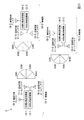
図8に示す3局の無線局からなる無線通信システム7を例にして、非特許文献1に示される従来の探索手順について図9を用いて説明する。この例では、無線局70−1〜70−3は、それぞれ60GHz帯の可変ビームアンテナと送受信機を備える。そのため、無線局70−1〜70−3は、高利得で鋭いビームを方向1から4までの範囲内で変化させることができる。また、可変ビームアンテナは、利得は低いが方向1〜4の範囲に対しほぼ一様な利得を有する準オムニビーム(quasi−omnidirectional beam)も形成することもできる。なお、無線通信システム7のネットワークトポロジは、無線局70−1を親局、無線局70−2および無線局70−3を子局とするスター型トポロジである。
A conventional search procedure shown in Non-Patent
図9(a)は、無線通信システム7における信号伝送のタイムチャートである。伝送される信号は、周期的なフレーム構造を有し、各フレームはビーム方向決定区間と、主信号通信区間とを含んで構成される。ビーム方向決定区間とは、各無線局の可変ビームアンテナのビーム方向を決定する区間である。主信号通信区間は、主信号による通信を行う区間である。主信号とは、相手先の通信局のユーザとの間で伝達する主な情報を含む信号である。 FIG. 9A is a time chart of signal transmission in the wireless communication system 7. The signal to be transmitted has a periodic frame structure, and each frame includes a beam direction determination section and a main signal communication section. The beam direction determination section is a section for determining the beam direction of the variable beam antenna of each radio station. The main signal communication section is a section in which communication using the main signal is performed. The main signal is a signal including main information transmitted with the user of the other communication station.
ビーム方向決定区間における処理手順を図9(b)に例示する。まず、無線局70−1は、方向探索信号を搬送するビームを送信する方向を方向1から方向4まで順次変更する。他方、無線局70−2は自局のビームの指向性を準オムニビームと定め、無線局70−1が送信した方向探索信号の受信状態を測定する。次に無線局70−2は、方向1から方向4までの各方向にビーム方向を順次向けて方向探索信号を送信する。そして、無線局70−1は自局の指向性を準オムニビームとし、受信した方向探索信号の受信状態を各ビーム方向について測定する。このとき、無線局70−2が送信する方向探索信号には、無線局70−1からの方向探索信号に関し、無線局70−2の受信状態が最良であった無線局70−1の送信方向情報が含まれる。無線局70−1は、受信した方向探索信号に基づいて無線局70−2との通信に用いるビーム方向を決定する。無線局70−2が方向1〜方向4のいずれに対して方向探索信号を送信した後、無線局70−1は無線局70−2からの方向探索信号のうち受信状態が最良となる送信方向を無線局70−2に通知する。無線局70−2は、この通知に従って無線局70−1との通信に用いるビーム方向を決定する。同様の手順が無線局70−1と無線局70−3の間でも実施される。よって、全ての相手局に対するビーム方向が決定される。上記ビーム方向決定区間は一定のフレーム周期毎に現れるため、ビーム方向は逐次更新される。
FIG. 9B illustrates the processing procedure in the beam direction determination section. First, the radio station 70-1 sequentially changes the direction in which the beam carrying the direction search signal is transmitted from
しかしながら、従来の方法では、送信側が方向探索信号を送信する間、受信側は準オムニビームで方向探索信号の到来を待機する必要がある。そのため、準オムニビームの形成機構を有しない無線局同士が高利得で鋭いビームのみを用いて方向探索する場合には適用できなかった。この場合、双方のビーム方向が全く未知である初期状態では、送信側がどの方向に方向探索信号を送信しても、送信側のビーム方向と受信側のビーム方向とが一致していなければ受信側の無線局は方向探索信号を受信できない。そのため、送信側のビーム方向を探索することができない。これを回避するために、受信側のビーム方向も送信側と協調(ネゴシーエーション)して走査させる手法も考えられる。しかしながら、初期状態では双方においてビーム方向の走査タイミングを同期させることが困難である。そのことから、探索時間が大幅に長延化する問題があった。 However, in the conventional method, while the transmission side transmits a direction search signal, the reception side needs to wait for the arrival of the direction search signal with a quasi-omni beam. For this reason, this technique cannot be applied to a case where wireless stations that do not have a quasi-omni beam forming mechanism perform a direction search using only a high gain and sharp beam. In this case, in the initial state where both beam directions are completely unknown, no matter which direction the transmitting side transmits the direction search signal, the transmitting side beam direction does not match the receiving side beam direction. Wireless stations cannot receive direction finding signals. Therefore, the beam direction on the transmission side cannot be searched. In order to avoid this, a method of scanning the beam direction on the reception side in cooperation with the transmission side (negotiation) is also conceivable. However, in the initial state, it is difficult to synchronize the scanning timing in the beam direction in both. Therefore, there has been a problem that the search time is greatly prolonged.
また、方向探索信号を送受信し、ビーム方向を決定するビーム方向決定区間では主信号を伝送できないが、従来の方法では、このビーム方向決定区間が一定のフレーム周期で設定される必要がある。これは、ビーム方向を相手局あるいは自局の移動や方向転換に追従することや、未知の地点から新たに通信を開始する無線局に対して最適方向を決定するためである。そのため、主信号の平均通信速度が低下する問題があった。通信を行う無線局の数が増えると、主信号の平均通信速度低下は一層顕著になる。
このような問題を回避するため、特許文献1に記載されているようにミリ波帯とは別の周波数の回線を使用して各無線局の位置情報を送信することも考えられる。しかしながら、特許文献1に記載の方法では、位置情報や可変ビームアンテナの角度基準が得られなければビーム方向を決定できず、かつ直接波以外で通信する場合には最適なビーム方向を予測することは困難であった。
In addition, although the main signal cannot be transmitted in the beam direction determination interval in which the direction search signal is transmitted and received and the beam direction is determined, in the conventional method, this beam direction determination interval needs to be set at a constant frame period. This is because the beam direction follows the movement or direction change of the partner station or the own station, or the optimum direction is determined for a radio station that newly starts communication from an unknown point. Therefore, there is a problem that the average communication speed of the main signal is lowered. As the number of radio stations performing communication increases, the average communication speed decrease of the main signal becomes more remarkable.
In order to avoid such a problem, as described in
本発明は上記の点に鑑みてなされたものであり、ビーム方向を確実に定め、安定した主信号の通信を実現することができる無線通信システム及び無線通信方法を提供することを目的とする。 The present invention has been made in view of the above points, and an object of the present invention is to provide a radio communication system and a radio communication method capable of reliably determining the beam direction and realizing stable main signal communication.
本発明は上記の課題を解決するためになされたものであり、本発明の一態様は、複数の無線局からなる無線通信システムであって、前記複数の無線局のうち少なくとも2つの無線局のそれぞれは、第1周波数帯の電波を伝送する第1アンテナと、前記第1周波数帯よりも周波数が低い第2周波数帯で電波を伝送する第2アンテナと、前記第1周波数帯で主信号を送受信する第1送受信部と、前記第2周波数帯で制御信号を送受信する第2送受信部と、を備え、前記少なくとも2つの無線局のうち、少なくとも1つの無線局は、前記第1アンテナとしてビーム方向が可変である可変ビームアンテナと、前記第2アンテナとして前記ビーム方向の可変範囲以上の放射範囲を有する広角アンテナと、前記制御信号に基づいて前記可変ビームアンテナのビーム方向を制御する制御部と、を備える無線通信システムである。 The present invention has been made to solve the above-described problem, and one aspect of the present invention is a wireless communication system including a plurality of wireless stations, wherein at least two of the plurality of wireless stations are connected. Each of the first antenna transmits radio waves in the first frequency band, the second antenna transmits radio waves in a second frequency band lower in frequency than the first frequency band, and the main signal in the first frequency band. A first transmission / reception unit for transmitting and receiving, and a second transmission / reception unit for transmitting and receiving a control signal in the second frequency band, and at least one of the at least two radio stations has a beam as the first antenna. A variable beam antenna having a variable direction; a wide-angle antenna having a radiation range greater than or equal to a variable range of the beam direction as the second antenna; and the variable beam antenna based on the control signal A control unit for controlling the beam direction, is a wireless communication system comprising a.
本発明の他の態様は、上述した無線通信システムであって、前記制御部は、前記制御信号として前記ビーム方向の探索に係る情報を他局から受信するとき、自局の可変ビームアンテナのビーム方向を探索することを特徴とする。 Another aspect of the present invention is the above-described wireless communication system, wherein the control unit receives a beam of a variable beam antenna of its own station when receiving information related to the search of the beam direction from the other station as the control signal. It is characterized by searching for directions.
本発明の他の態様は、上述した無線通信システムであって、前記制御部は、前記主信号の伝送状態を測定し、前記伝送状態が所定の伝送状態よりも劣るとき、前記制御信号として前記ビーム方向の探索に係る情報を他局に送信する。 Another aspect of the present invention is the above-described wireless communication system, wherein the control unit measures a transmission state of the main signal, and when the transmission state is inferior to a predetermined transmission state, the control signal is the control signal. Information related to the beam direction search is transmitted to another station.
本発明の他の態様は、上述した無線通信システムであって、前記少なくとも1つの無線局は、前記可変ビームアンテナとして、前記第1周波数帯の電波を送信する送信可変ビームアンテナと、前記第1周波数帯の電波を受信する受信可変ビームアンテナとを備え、前記制御部は、前記送信可変ビームアンテナのビーム方向と自局の前記受信可変ビームアンテナのビーム方向を独立に定める。 Another aspect of the present invention is the above-described wireless communication system, wherein the at least one wireless station transmits, as the variable beam antenna, a transmission variable beam antenna that transmits radio waves in the first frequency band, and the first A variable reception antenna that receives radio waves in a frequency band, and the control unit independently determines a beam direction of the transmission variable beam antenna and a beam direction of the reception variable beam antenna of the local station.
本発明の他の態様は、上述した無線通信システムであって、前記第2周波数帯における伝送速度は、前記第1周波数帯における伝送速度よりも低い。 Another aspect of the present invention is the above-described wireless communication system, wherein a transmission rate in the second frequency band is lower than a transmission rate in the first frequency band.
本発明の他の態様は、複数の無線局からなる無線通信システムにおける無線通信方法であって、前記複数の無線局のうち、少なくとも2つの無線局のそれぞれは、第1周波数帯の電波を伝送する第1アンテナと、前記第1周波数帯よりも周波数が低い第2周波数帯で電波を伝送する第2アンテナと、を備え、前記第1周波数帯で主信号を送受信する第1送受信過程と、前記第2周波数帯で制御信号を送受信する第2送受信過程と、を有し、前記少なくとも2つの無線局のうち、少なくとも1つの無線局は、前記第1アンテナとしてビーム方向が可変である可変ビームアンテナと、前記第2アンテナとして前記ビーム方向の可変範囲以上の放射範囲を有する広角アンテナと、を備え、前記制御信号に基づいて前記可変ビームアンテナのビーム方向を制御する制御過程、を有する無線通信方法。 Another aspect of the present invention is a wireless communication method in a wireless communication system including a plurality of wireless stations, and at least two of the plurality of wireless stations transmit radio waves in a first frequency band. A first antenna for transmitting and receiving a main signal in the first frequency band, and a second antenna for transmitting radio waves in a second frequency band having a frequency lower than the first frequency band; A second transmission / reception process for transmitting / receiving a control signal in the second frequency band, wherein at least one of the at least two radio stations has a variable beam whose beam direction is variable as the first antenna. An antenna and a wide-angle antenna having a radiation range that is greater than or equal to the variable range of the beam direction as the second antenna, and the beam direction of the variable beam antenna based on the control signal Control process, the wireless communication method having controlled.
本発明の一態様によれば、可変ビームアンテナのビーム方向の制御に要する情報が、ビーム方向と無線局との位置関係によって伝送品質が大きく変化する第1周波数帯ではなく、ビーム方向に大きく依存せず一定の伝送品質が得られる第2周波数帯を介して伝送される。このため、第1周波数帯による伝送品質によらず自局のビーム方向と相手局のビーム方向の組み合わせを確実に定めることができる。そのため、安定した主信号の通信を実現することができる。 According to one aspect of the present invention, the information required for controlling the beam direction of the variable beam antenna is largely dependent on the beam direction, not the first frequency band in which the transmission quality varies greatly depending on the positional relationship between the beam direction and the radio station. Without being transmitted through the second frequency band where constant transmission quality can be obtained. For this reason, the combination of the beam direction of the local station and the beam direction of the counterpart station can be reliably determined regardless of the transmission quality of the first frequency band. Therefore, stable main signal communication can be realized.
以下、図面を参照して、本発明の無線通信システム及び無線通信方法の実施形態について説明する。 Hereinafter, embodiments of a wireless communication system and a wireless communication method of the present invention will be described with reference to the drawings.
(第1の実施形態)
まず、本発明の第1の実施形態に係る無線通信システムの一構成例について説明する。
図1は、本実施形態に係る無線通信システムの一構成例を示すブロック図である。
無線通信システム1は、3個の無線局10−1〜10−3を含んで構成される。図1に示す例では、無線通信システムのネットワークトポロジは、スター型である。無線局10−1〜10−3のうち、無線局10−1が親局、無線局10−2、10−3が子局である。なお、無線局間で共通の事項を説明する場合、無線局を特定しない場合には、無線局10と総称し、10−1の符号の末尾である−1を省略する。
(First embodiment)
First, a configuration example of the wireless communication system according to the first embodiment of the present invention will be described.
FIG. 1 is a block diagram illustrating a configuration example of a wireless communication system according to the present embodiment.
The
無線局10−1〜10−3は、それぞれ60GHz帯送受信機12−1〜12−3と、960MHz帯送受信機14−1〜14−3と、可変ビームアンテナ16−1〜16−3と、無指向性アンテナ19−1〜19−3と、を含んで構成される。60GHz帯送受信機12は、可変ビームアンテナ16を用いて60GHz帯の電波を送信ならびに受信する。60GHz帯の電波は、波長が1〜10mm(周波数30〜300GHz)であるミリ波に属する。ミリ波は、直進性が強いうえ、空気中で伝搬する際、吸収や散乱の影響を強く受ける。そのため、ミリ波を十分な電界強度で受信するために、可変ビームアンテナ16−1〜16−3は、ある1つの方向に他の方向よりも強い指向性を有するビームを放射する。ビームの放射指向性において放射強度が最も高い方向をビーム方向と呼ぶ。一般に、ビームの放射指向性は、受信指向性に相当する。即ち、ビーム方向から到来する電波の受信感度が他の方向からの受信感度よりも高くなる。960MHz帯送受信機14は、無指向性アンテナ19を用いて960MHz帯の電波を送信ならびに受信する。960MHz帯は、波長が10〜1m(周波数300MHz〜3GHz)であるUHF(Ultra High Frequency)に属する帯域である。UHF帯域の電波は、ミリ波よりも周波数が低いので、直進性が強くない。必ずしも指向性を有するビームを放射する必要はない。図1に示す例では、UHF帯域の電波を送受信するため無指向性アンテナ19−1〜19−3が用いられている。
The radio stations 10-1 to 10-3 are respectively 60 GHz band transceivers 12-1 to 12-3, 960 MHz band transceivers 14-1 to 14-3, variable beam antennas 16-1 to 16-3, And omnidirectional antennas 19-1 to 19-3. The 60 GHz band transceiver 12 transmits and receives 60 GHz band radio waves using the
ある無線局10−1から送信されるビームは、地面、建造物、構造物、その他の物体の表面において反射して他の無線局10−2で受信されることがある。そのため、無線局10−1が送信するビームのビーム方向が、無線局10−1から無線局10−2の方向に一致するとき、無線局10−2における受信強度が最も高くなるとは限らない。また、無線局10−1、10−2間のビームの伝搬経路は、無線局10−1、10−2間の物体の有無や、その配置に依存する。そこで、無線局10−1、10−2は、相互に良好な受信状態を得るために所定時間毎にビーム方向を制御する。図1に示す例では、各無線局は、可変ビームアンテナ16のビーム方向を、4方向(方向1〜方向4)のいずれかに定める。
A beam transmitted from one radio station 10-1 may be reflected by the surface of the ground, a building, a structure, or another object and received by another radio station 10-2. Therefore, when the beam direction of the beam transmitted by the radio station 10-1 matches the direction from the radio station 10-1 to the radio station 10-2, the reception intensity at the radio station 10-2 is not always the highest. The beam propagation path between the radio stations 10-1 and 10-2 depends on the presence or absence of an object between the radio stations 10-1 and 10-2 and the arrangement thereof. Therefore, the radio stations 10-1 and 10-2 control the beam direction every predetermined time in order to obtain a good reception state. In the example illustrated in FIG. 1, each radio station determines the beam direction of the
(無線局の構成)
次に、本実施形態に係る無線局10の構成について説明する。
図2は、本実施形態に係る無線局10の一構成例を示すブロック図である。
無線局10は、第1送受信部112と、第2送受信部114と、第1アンテナ16と、第2アンテナ19と、制御部120と、を含んで構成される。
(Configuration of radio station)
Next, the configuration of the
FIG. 2 is a block diagram illustrating a configuration example of the
The
第1送受信部112は、第1アンテナ16に他の無線局10との間で信号を第1周波数帯の電波で伝送させる。第1送受信部112は、上述した60GHz帯送受信機12に相当する。第1送受信部112は、制御部120から入力される送信信号の帯域を基底帯域(ベースバンド)からアップコンバートして得られる第1周波数帯の送信信号を第1アンテナ16に供給する。また、第1送受信部112は、第1アンテナ16から入力される第1周波数帯の受信信号をダウンコンバートして得られる基底帯域の受信信号を制御部120に出力する。第1周波数帯は、ミリ波帯(例えば、60Hz帯)である。
The first transmission /
また、第1送受信部112は、通信制御部122から入力される方向制御信号が示すビーム方向に、第1アンテナ16が放射するビーム方向を制御する。第1送受信部112は、ビーム方向を制御するための部材として、例えば、移相器を備える。移相器は、第1アンテナ16を構成するアンテナ素子毎の受信信号もしくは送信信号の位相を可変にする。アンテナ素子間の位相差は、所定のアンテナ素子の間隔と波長のもとでビーム方向に対応する。第1送受信部112は、アンテナ素子間でビーム方向に対応した位相差が与えられた受信信号をアンテナ素子間で合成し、合成して得られる合成受信信号をダウンコンバート対象の受信信号とする。移相器は、アップコンバートして得られる送信信号に対してアンテナ素子間でビーム方向に位相差を与え、位相差が与えられた送信信号を各アンテナ素子に供給する。ここで、第1送受信部112は、予めビーム方向とアンテナ素子毎の位相とを対応付けてなるデータテーブルを設定しておいてもよい。第1送受信部112は、設定されたデータテーブルを参照し、方向制御信号が示すビーム方向に対応するアンテナ素子毎の位相を特定する。
The first transmission /
第2送受信部114は、第2アンテナ19に他の無線局10との間で信号を第2周波数帯の電波で伝送させる。第2送受信部114は、上述した960MHz帯送受信機14に相当する。第2送受信部114は、制御部120から入力される送信信号の帯域を基底帯域からアップコンバートして得られる第2周波数帯の送信信号を第2アンテナ19に供給する。また、第2送受信部114は、第2アンテナ19から入力される第2周波数帯の受信信号をダウンコンバートして得られる基底帯域の受信信号を制御部120に出力する。第2周波数帯は、第1周波数帯よりも十分に低い周波数帯域(例えば、960MHz帯)であればよい。また、第2周波数帯の帯域幅(伝送速度)は、第1周波数帯の帯域幅(伝送速度)よりも狭く(遅く)てもよい。第1周波数帯は、主に主信号の伝送に用いられるのに対し、第2周波数帯は、主に制御信号の伝送に用いられる。
The second transmission /
第1アンテナ16は、第1周波数帯の電波をビームとして送信又は受信する。第1アンテナ16は、ビーム方向を可変とする可変ビームアンテナである。第1アンテナ16は、上述した可変ビームアンテナ16−1〜16−3に相当する。第1アンテナ16は、ビーム方向を制御するための構成として、例えば、複数のアンテナ素子を備える。複数のアンテナ素子は、一定方向に所定の間隔で規則的に配列される。各アンテナ素子から、指示されるビーム方向へ放射される電波の波面の位相を揃えることで、利得が高く、幅が狭いビームが形成される。アンテナ素子の配列は、例えば、2次元配列である。2次元配列によれば、アンテナ素子の配列面に対する法線方向を中心軸とする半球面内の各方向にビーム方向を制御することができる。第1アンテナ16は、例えば、マイクロストリップアンテナである。上記の説明では、第1アンテナ16と移相器がフェーズドアレイを形成して、ビーム方向を可変にしている場合を例にしたが、これには限られない。第1アンテナ16は、例えば、ビーム方向が固定されている導波素子と、その導波素子を支持し、その向きを機械的に回転可能とする支持部とを備えて構成されてもよい。
The
第2アンテナ19は、第2周波数帯の電波を送信又は受信する。第2アンテナ19は、その指向性の幅が所定の幅よりも広い広角アンテナである。第2アンテナ19の指向性の幅は、第1アンテナ16のビーム方向の可変範囲以上であればよい。例えば、第1アンテナ16のビーム方向の可変範囲が半球面内の各方向である場合には、第2アンテナ19のビーム幅は、180°以上であればよい。ビーム幅は、方向間の放射強度が最大となる最大放射強度(ピーク強度)よりも3dB低い放射強度以上の放射強度が得られる放射方向の範囲である。従って、第2アンテナ19は、無指向性アンテナであってもよい。第2アンテナ19は、図1に示す無指向性アンテナ19−1〜19−3に相当する。また、第2アンテナ19の指向性は、固定されていてもよい。
The
制御部120は、通信制御部122を備える。制御部120は、例えば、CPU(Central Processing Unit)、ASIC(Application Specific Integrated Circuit)などの制御デバイスを含んで構成される。制御デバイスは、所定の制御プログラムに記述された命令が指示する処理を実行することで、その機能を実現してもよい。また、制御部120は、専用の部材で構成されてもよい。
The
通信制御部122は、他の無線局10との通信を制御する。以下、図3を参照しながら通信制御部122が行う処理について説明する。図3は、親局である無線局10−1と子局である無線局10−2との間で行われる制御を例にする。以下の説明では、子局とは接続要求を行う無線局、親局とは接続要求を受け付ける無線局を意味し、必ずしもネットワークトポロジ上の無線局の役割と一致していなくてもよい。無線局10−1、10−2の各構成部を特定する場合には、それぞれ子番号−1、−2を用いる。無線局10に共通の事項、その他、無線局10を特定しない場合には、子番号を用いないものとする。無線局10−2の通信制御部122−2は、第2送受信部114−2を介して予め所定の通信方式を用いて、無線局10−1との間で接続を確立する。第2送受信部114−2を介した通信において、例えば、IEEE802.15.4e、IEEE802.15.4gなどの通信方式が利用可能である。無線局10−1、10−2間で各種の信号を送受信する期間には、図3(a)に示すようにビーム方向決定区間と主信号通信区間とがある。ビーム方向決定区間は、無線局10−1、10−2間で相互に第1アンテナ16−1、16−2のビーム方向を決定する期間である。主信号通信区間は、無線局10−1、10−2間で主信号を送信又は受信する期間である。ビーム方向決定区間と主信号通信区間は、所定の周期で順次に繰り返されてもよい。その周期毎に通信を行う無線局10の対(ペア)が異なっていてもよいし、一定であってもよい。
また、通信開始に伴う接続要求がなされる毎にビーム方向決定区間が開始されてもよい。
The
In addition, the beam direction determination section may be started each time a connection request accompanying the start of communication is made.
通信制御部122は、ビーム方向決定区間において、ビーム方向を決定するための制御信号を他の無線局との間で相互に第2送受信部114を介して送受信する。送受信される制御信号には、接続要求信号、受信走査開始信号、終了信号などがある。接続要求信号は、子局から親局に対する接続要求を示す信号である。受信走査開始信号は、親局から子局に対してビーム方向の走査の開始を指示する信号である。終了信号とは、子局が、自局におけるビーム方向の走査の終了を親局に通知する信号である。終了信号には、自局において受信状態が最も良好な自局のビーム方向と、その受信状態を示す指標値の情報が付加される。指標値として、受信電力、搬送波レベル対干渉雑音比、信号対干渉雑音比、ビット誤り率、などが利用可能である。受信電力、信号対干渉雑音比は、それぞれ値が大きいほど受信状態が良好であることを示す指標値である。ビット誤り率は、その値が小さいほど受信状態が良好であることを示す指標値である。
The
親局である無線局10−1の通信制御部122−1は、図3(b)に示すように子局である無線局10−2から終了信号を受信するまで、1通りのビーム方向で方向探索信号を第1アンテナ16−1から放射する。このため、通信制御部122−1は、方向探索信号を送信信号として、そのビーム方向を示す情報を方向制御信号として、それぞれ第1送受信部112−1に出力する。方向探索信号は、指標値の測定に用いられる参照信号である。方向探索信号として、予め送信強度、周波数成分、ビット系列などの特性が既知である参照信号が利用可能である。 As shown in FIG. 3B, the communication control unit 122-1 of the radio station 10-1 that is the master station uses one beam direction until it receives an end signal from the radio station 10-2 that is the slave station. A direction search signal is radiated from the first antenna 16-1. For this reason, the communication control unit 122-1 outputs the direction search signal as a transmission signal and information indicating the beam direction as a direction control signal to the first transmission / reception unit 112-1. The direction search signal is a reference signal used for measuring the index value. As the direction search signal, a reference signal whose characteristics such as transmission intensity, frequency component, and bit sequence are known in advance can be used.
他方、子局である無線局10−2の通信制御部122−2は、図3(b)に示すように、無線局10−1から1通りのビーム方向で方向探索信号が送信されている間、第1アンテナ16−2にビーム方向の走査を指示するために、異なるビーム方向を示す方向制御信号を順次第1送受信部112−2に出力する。このビーム方向の走査を、受信走査開始信号を受信する毎に繰り返す。また、通信制御部122−2は、第1送受信部112−2から入力される受信信号を用いて、その受信状態を示す指標値を自局の第1アンテナ16−2のビーム方向毎に測定する。その後、通信制御部122−2は、無線局10−1のビーム方向と無線局10−2のビーム方向との組合せ毎に測定された指標値を比較し、最も良好な指標値に係る無線局10−1のビーム方向と無線局10−2ビーム方向の組み合わせを定める。無線局10−2の通信制御部122−2は、定めた組み合わせに係る自局のビーム方向を示す方向制御信号を第1送受信部112−2に出力する。従って、無線局10−2の第1アンテナ16−2は、方向制御信号で指示されたビーム方向で第1周波数帯の電波を送受信することができる。他方、無線局10−1の通信制御部122−1は、第2送受信部114−1を介して無線局10−2から受信した終了信号に付加された受信状態を示す指標値を無線局10−1のビーム方向間で比較し、最も良好な指標値に係る無線局10−1のビーム方向を定める。従って、無線局10−1においても無線局10−2のビーム方向と無線局10−1のビーム方向との組合せ毎に測定された指標値のうち最も良好な指標値が特定される。無線局10−1の通信制御部122−1は、定めたビーム方向を示す方向制御信号を第1送受信部112−1に出力する。従って、無線局10−1の第1アンテナ16−1は、方向制御信号が示すビーム方向で第1周波数帯の電波を送受信することができる。ビーム方向決定手順の例については、後述する。 On the other hand, as shown in FIG. 3B, the communication control unit 122-2 of the radio station 10-2 that is a child station transmits a direction search signal in one beam direction from the radio station 10-1. In the meantime, in order to instruct the first antenna 16-2 to scan in the beam direction, direction control signals indicating different beam directions are sequentially output to the first transmitting / receiving unit 112-2. This scanning in the beam direction is repeated every time a reception scanning start signal is received. Also, the communication control unit 122-2 uses the received signal input from the first transmission / reception unit 112-2 to measure an index value indicating the reception state for each beam direction of the first antenna 16-2 of the own station. To do. After that, the communication control unit 122-2 compares the index values measured for each combination of the beam direction of the radio station 10-1 and the beam direction of the radio station 10-2, and the radio station related to the best index value. The combination of the beam direction of 10-1 and the beam direction of the radio station 10-2 is determined. The communication control unit 122-2 of the radio station 10-2 outputs a direction control signal indicating the beam direction of the own station related to the determined combination to the first transmission / reception unit 112-2. Therefore, the first antenna 16-2 of the radio station 10-2 can transmit and receive radio waves in the first frequency band in the beam direction indicated by the direction control signal. On the other hand, the communication control unit 122-1 of the wireless station 10-1 uses the index value indicating the reception state added to the end signal received from the wireless station 10-2 via the second transmission / reception unit 114-1 as the wireless station 10-1. -1 beam directions are compared, and the beam direction of the radio station 10-1 related to the best index value is determined. Therefore, the radio station 10-1 also identifies the best index value among the index values measured for each combination of the beam direction of the radio station 10-2 and the beam direction of the radio station 10-1. The communication control unit 122-1 of the radio station 10-1 outputs a direction control signal indicating the determined beam direction to the first transmission / reception unit 112-1. Therefore, the first antenna 16-1 of the radio station 10-1 can transmit and receive radio waves in the first frequency band in the beam direction indicated by the direction control signal. An example of the beam direction determination procedure will be described later.
図2に戻り、通信制御部122は、主信号通信区間において、第1送受信部112を介して相手局と主信号を送受信する。主信号とは、自局又は相手局のユーザが伝達しようとする情報もしくはその情報を搬送する信号である。主信号は、例えば、音声信号、映像信号、テキストなど各種のデータが該当する。主信号は、ユーザデータとも呼ばれる。通信制御部122は、自局で取得した主信号を送信信号として第1送受信部112を介して相手局に送信する。通信制御部122は、相手局から第1送受信部112を介して主信号を受信信号として受信する。
Returning to FIG. 2, the
(ビーム方向決定手順)
次に、本実施形態に係るビーム方向決定手順の一例について説明する。
図3(b)は、本実施形態に係るビーム方向決定手順の一例を示す。図3(b)は、次の点を前提として、無線通信システム1において子局である無線局10−2から親局である無線局10−1に対して第1周波数帯として60GHz帯を用いた通信を要求する場合を例にする。
・無線局10−1の第2送受信部114−1と無線局10−2の第2送受信部114−2は、相互に第2周波数帯として920MHz帯を用いて、予め接続が確立している。
・無線局10−1の第1送受信部112−1、無線局10−2の第1送受信部112−2が、第1アンテナ16−1、第1アンテナ16−2のビーム方向を、それぞれ4通りのビーム方向1〜4のいずれかに設定可能とする。
・無線局10−1の通信制御部122−1、無線局10−2の通信制御部122−2には、それぞれ無線局10−1の第1アンテナ16−1、無線局10−2の第1アンテナ16−2が設定可能とするビーム方向数と、ビーム方向の探索におけるビーム方向の順序がビーム方向の番号の昇順に予め設定されている。
・1個のビーム方向決定区間内において、接続要求から無線局10−1でのビーム方向と、無線局10−2でのビーム方向の決定までの一連の手順を実行する。
(Beam direction determination procedure)
Next, an example of a beam direction determination procedure according to the present embodiment will be described.
FIG. 3B shows an example of a beam direction determination procedure according to the present embodiment. FIG. 3 (b) uses the 60 GHz band as the first frequency band from the radio station 10-2 as a slave station to the radio station 10-1 as a master station in the
The connection between the second transmission / reception unit 114-1 of the wireless station 10-1 and the second transmission / reception unit 114-2 of the wireless station 10-2 is established in advance using the 920 MHz band as the second frequency band. .
The first transmission / reception unit 112-1 of the wireless station 10-1 and the first transmission / reception unit 112-2 of the wireless station 10-2 change the beam directions of the first antenna 16-1 and the first antenna 16-2 to 4 respectively. It can be set to any one of the
The communication control unit 122-1 of the wireless station 10-1 and the communication control unit 122-2 of the wireless station 10-2 are respectively connected to the first antenna 16-1 of the wireless station 10-1 and the first of the wireless station 10-2. The number of beam directions that can be set by one antenna 16-2 and the order of the beam directions in the search for the beam direction are preset in ascending order of the beam direction numbers.
In a single beam direction determination section, a series of procedures from connection request to determination of the beam direction at the radio station 10-1 and the beam direction at the radio station 10-2 are executed.
まず、無線局10−2の通信制御部122−2は、第2送受信部114−2を介して接続要求信号を無線局10−1に送信する。
無線局10−1の通信制御部122−1は、第2送受信部114−1を介して無線局10−2から接続要求信号を受信する。この接続要求信号をトリガとしてビーム方向決定区間が開始される。このとき、通信制御部122−1は、第2送受信部114−1を介して受信走査開始信号を送信し、第1送受信部112−1を介して第1アンテナ16−1にビーム方向1で方向探索信号を送信させる。また、通信制御部122−1が、第1送受信部112−1を介して主信号を送信している場合には、その送信を停止する。通信制御部122−1は、第1送受信部112−1にビーム方向1を示す方向制御信号を出力し、送信信号として方向探索信号を送信させる。よって、通信制御部122−1は、ビーム方向1について無線局10−2に対してビーム方向探索処理を実行させることができる。
First, the communication control unit 122-2 of the wireless station 10-2 transmits a connection request signal to the wireless station 10-1 via the second transmission / reception unit 114-2.
The communication control unit 122-1 of the wireless station 10-1 receives the connection request signal from the wireless station 10-2 via the second transmission / reception unit 114-1. The beam direction determination section is started by using this connection request signal as a trigger. At this time, the communication control unit 122-1 transmits a reception scanning start signal via the second transmission / reception unit 114-1, and the
無線局10−2の通信制御部122−2は、第2送受信部114−2を介して受信走査開始信号を受信し、第1送受信部112−2を介して無線局10−1からの方向探索信号を受信する。このとき、通信制御部122−2は、無線局10−2の第1アンテナ16−2についてビーム方向探索処理を行う。通信制御部122−2が、第1送受信部112−2を介して主信号を送信している場合には、その送信を停止する。
ビーム方向探索処理において、通信制御部122−2は、自局のビーム方向毎に、第1送受信部112−2を介して受信する方向探索信号について受信状態を示す指標値を測定する。そこで、通信制御部122−2は、ビーム方向1を示す方向制御信号を第1送受信部112−2に送信させ、その後、第1送受信部112−2を介して受信した方向探索信号について指標値を測定する。通信制御部122−2は、第1送受信部112−2に設定するビーム方向をビーム方向2、3、4に順次切り替え、各ビーム方向について入力される方向探索信号について指標値を測定する。その後、通信制御部122−2は、測定した指標値のうち、最も良好な受信状態を示す指標値を特定し、特定した指標値に対応するビーム方向を、無線局10−2のビーム方向として特定する。通信制御部122−2は、無線局10−1のビーム方向1について無線局10−2におけるビーム方向探索処理の終了を示す終了信号を、第2送受信部114−2を介して無線局10−1に送信する。この終了信号には、特定された指標値と特定した無線局10−2のビーム方向の情報が付加される。無線局10−1の通信制御部122−1は、第2送受信部114−1を介して無線局10−2から終了信号を受信する。
The communication control unit 122-2 of the radio station 10-2 receives the reception scanning start signal via the second transmission / reception unit 114-2, and the direction from the radio station 10-1 via the first transmission / reception unit 112-2. A search signal is received. At this time, the communication control unit 122-2 performs beam direction search processing for the first antenna 16-2 of the radio station 10-2. When the communication control unit 122-2 is transmitting the main signal via the first transmission / reception unit 112-2, the transmission is stopped.
In the beam direction search process, the communication control unit 122-2 measures an index value indicating a reception state for a direction search signal received via the first transmission / reception unit 112-2 for each beam direction of the local station. Therefore, the communication control unit 122-2 causes the first transmission / reception unit 112-2 to transmit a direction control signal indicating the
そして、無線局10−1の通信制御部122−1は、終了信号の受信毎に、第1送受信部112−1に設定するビーム方向をビーム方向2、3、4に順次切り替え、各ビーム方向について無線局10−2に対してビーム方向探索処理を実行させる。無線局10−2の通信制御部122−2は、実行を完了したビーム方向探索処理の回数を計数する。
無線局10−1の通信制御部122−1は、無線局10−1の各ビーム方向について無線局10−2から終了信号を受信し、その終了信号の受信回数を計数する。
Then, each time the end signal is received, the communication control unit 122-1 of the radio station 10-1 sequentially switches the beam direction set in the first transmission / reception unit 112-1 to the
The communication control unit 122-1 of the radio station 10-1 receives an end signal from the radio station 10-2 for each beam direction of the radio station 10-1, and counts the number of times the end signal is received.
無線局10−2の通信制御部122−2は、実行を完了したビーム方向探索処理の回数が4回に達したとき、無線局10−1の各ビーム方向についてビーム方向探索処理が完了したと判定する。このとき、通信制御部122−2は、無線局10−1のビーム方向と無線局10−2のビーム方向の組み合わせ毎に測定した指標値のうち、最も良好な受信状態を示す指標値を与えるビーム方向の組み合わせを選択する。無線局10−2の通信制御部122−2は、選択した組み合わせから無線局10−2のビーム方向を特定し、特定したビーム方向を示す方向制御信号を第1送受信部112−2に出力する。よって、無線局10−2の第1アンテナの16−2のビーム方向が、その特定した方向に設定される。 The communication control unit 122-2 of the radio station 10-2 determines that the beam direction search process has been completed for each beam direction of the radio station 10-1 when the number of beam direction search processes that have been executed reaches four. judge. At this time, the communication control unit 122-2 gives an index value indicating the best reception state among the index values measured for each combination of the beam direction of the radio station 10-1 and the beam direction of the radio station 10-2. Select a combination of beam directions. The communication control unit 122-2 of the radio station 10-2 specifies the beam direction of the radio station 10-2 from the selected combination, and outputs a direction control signal indicating the specified beam direction to the first transmission / reception unit 112-2. . Therefore, the beam direction of 16-2 of the first antenna of the radio station 10-2 is set to the specified direction.
他方、無線局10−1の通信制御部122−1は、無線局10−2からの終了信号の受信回数が4回に達したとき、無線局10−1の各ビーム方向についてビーム方向探索処理が完了したと判定する。通信制御部122−1は、第1送受信部112−1への方向探索信号の出力を停止し、無線局10−1の各ビーム方向に係る終了信号に付加された指標値のうち、最も良好な受信状態を示す指標値に対応するビーム方向を特定する。通信制御部122−1は、特定した無線局10−1のビーム方向を示す方向制御信号を第1送受信部112−1に出力する。よって、無線局10−1の第1アンテナの16−1のビーム方向が、その特定した方向に設定される。 On the other hand, the communication control unit 122-1 of the radio station 10-1 performs beam direction search processing for each beam direction of the radio station 10-1 when the number of times of reception of the end signal from the radio station 10-2 reaches four times. Is determined to be complete. The communication control unit 122-1 stops outputting the direction search signal to the first transmission / reception unit 112-1 and is the best index value added to the end signal related to each beam direction of the radio station 10-1. The beam direction corresponding to the index value indicating the correct reception state is specified. The communication control unit 122-1 outputs a direction control signal indicating the beam direction of the specified radio station 10-1 to the first transmission / reception unit 112-1. Therefore, the beam direction of the first antenna 16-1 of the radio station 10-1 is set to the specified direction.
その後、無線局10−1の通信制御部122−1は第1送受信部112−1を介して、無線局10−2の通信制御部122−2は第1送受信部112−2を介して、相互間で主信号の通信を開始する。従って、ビーム方向決定区間が終了し、主信号通信区間が開始される。 Thereafter, the communication control unit 122-1 of the radio station 10-1 is sent via the first transmission / reception unit 112-1, and the communication control unit 122-2 of the radio station 10-2 is sent via the first transmission / reception unit 112-2. Start communication of main signals between each other. Therefore, the beam direction determination section ends and the main signal communication section starts.
(他の無線局による通信開始)
上述した、ビーム方向決定手順は、無線局10−1、10−2の対とは、他の対において実行されてもよい。例えば、無線局10−1と無線局10−2との主信号の通信中において、通信中の無線局10−1、10−2とは別個の無線局10−3が無線局10−1との通信を要求する場合にビーム方向決定手順が開始されてもよい。
このとき、図4(b)に示すように、無線局10−3の通信制御部122−3は、第2送受信部114−3を介して接続要求信号を無線局10−1に送信する。無線局10−1の通信制御部122−1は、第2送受信部114−1を介して無線局10−3から接続要求信号を受信する。この接続要求信号の受信に応じて、無線局10−1の通信制御部122−1は、第1送受信部112−1を介した無線局10−2への主信号の送信、無線局10−2からの主信号の受信を停止させる。その後、無線局10−3との間で上述したビーム方向決定手順を実行する。ビーム方向決定手順により、無線局10−3の通信制御部122−3と無線局10−1の通信制御部122−1は、それぞれ最も良好な受信状態を示す指標値に係る組み合わせとして、無線局10−1のビーム方向と無線局10−3のビーム方向の組み合わせを定める。その後、無線局10−3の通信制御部122−3、無線局10−1の通信制御部122−1は、それぞれ第1送受信部112−3、112−1を介して、各無線局について定められたビーム方向で主信号の送受信を開始する。
(Communication started by other radio stations)
The beam direction determination procedure described above may be executed in a pair other than the pair of the radio stations 10-1 and 10-2. For example, during the communication of the main signal between the radio station 10-1 and the radio station 10-2, the radio station 10-3 separate from the radio stations 10-1 and 10-2 being communicated with the radio station 10-1 The beam direction determination procedure may be started when requesting the communication.
At this time, as illustrated in FIG. 4B, the communication control unit 122-3 of the wireless station 10-3 transmits a connection request signal to the wireless station 10-1 via the second transmission / reception unit 114-3. The communication control unit 122-1 of the wireless station 10-1 receives the connection request signal from the wireless station 10-3 via the second transmission / reception unit 114-1. In response to the reception of the connection request signal, the communication control unit 122-1 of the radio station 10-1 transmits the main signal to the radio station 10-2 via the first transmission / reception unit 112-1, and the radio station 10- The reception of the main signal from 2 is stopped. Thereafter, the above-described beam direction determination procedure is executed with the radio station 10-3. According to the beam direction determination procedure, the communication control unit 122-3 of the wireless station 10-3 and the communication control unit 122-1 of the wireless station 10-1 each have a wireless station as a combination related to the index value indicating the best reception state. The combination of the beam direction of 10-1 and the beam direction of the radio station 10-3 is determined. Thereafter, the communication control unit 122-3 of the wireless station 10-3 and the communication control unit 122-1 of the wireless station 10-1 determine the respective wireless stations via the first transmission / reception units 112-3 and 112-1. Transmission / reception of the main signal is started in the beam direction.
以上に説明したように、本実施形態に係る無線通信システム1は、複数の無線局10からなる。複数の無線局10のうち少なくとも2台の無線局10のそれぞれは、第1周波数帯で主信号を伝送する第1送受信部112と、第1周波数帯よりも周波数が低い第2周波数帯で制御信号を伝送する第2送受信部114と、を備える。また、少なくとも2台の無線局10のそれぞれは、第1周波数帯の電波を伝送し、ビーム方向が可変である第1アンテナ16と、第2周波数帯の電波を伝送し、第1アンテナ16のビーム方向の可変範囲以上の放射範囲を有する第2アンテナ19と、制御信号に基づいて第1アンテナのビーム方向を制御する通信制御部122とを備える。
As described above, the
この構成によれば、第1アンテナ16のビーム方向の制御に要する情報が、ビーム方向と無線局10との位置関係によって伝送品質が大きく変化する第1周波数帯ではなく、ビーム方向に大きく依存せず一定の伝送品質が得られる第2周波数帯を介して伝送される。このため、第1周波数帯による伝送品質によらず自局のビーム方向と相手局のビーム方向の組み合わせを確実に定めることができる。例えば、相手局が自局のビーム方向から外れることで回線断あるいは信号強度が低下した場合でも、速やかにビーム方向を更新し通信を回復することができる。
According to this configuration, the information required for controlling the beam direction of the
また、第2周波数帯を用いた制御により、第1周波数帯で伝送される方向探索信号を、ビーム方向探索に必要とされるタイミングで送受信できる。例えば、新たな無線局10が通信を開始させる場合など、ビーム方向の探索が必要となる場合に主信号の送信を中断して方向探索信号を送信させ、それ以外の場合に主信号の送信を継続できる。そのため、主信号の平均通信速度の低下を抑制することができる。
また、第2周波数帯は、第1周波数帯よりも周波数が低いため、第2周波数帯での単位距離当たりの伝搬損失が第1周波数帯よりも小さくなる。そのため、第2アンテナ19が利得の低い広角アンテナであっても、利得が高い第1アンテナ16を用いて伝送される主信号より低い送信電力で、主信号と同等以上の距離に到達させることができる。
また、第2周波数帯の伝送速度は、第1周波数帯の伝送速度よりも低く設定されるため、伝搬損失に対するマージンが大きくなる。そのため、第2アンテナ19が利得の低い広角アンテナであっても、利得が高い第1アンテナ16を用いて伝送される主信号よりさらに低い送信電力で、主信号と同等以上の距離に到達させることができる。
Further, the direction search signal transmitted in the first frequency band can be transmitted and received at the timing required for the beam direction search by the control using the second frequency band. For example, when a
Moreover, since the frequency of the second frequency band is lower than that of the first frequency band, the propagation loss per unit distance in the second frequency band is smaller than that of the first frequency band. Therefore, even if the
Further, since the transmission rate in the second frequency band is set lower than the transmission rate in the first frequency band, a margin for propagation loss increases. Therefore, even if the
(第2の実施形態)
次に、本発明の第2の実施形態について説明する。次の説明では、主に上記の実施形態との差異点を主とする。上記の実施形態と同一の構成については、同一の符号を付してその説明を援用する。
図5は、本実施形態に係る無線通信システムの一構成例を示すブロック図である。
無線通信システム1を構成する無線局10−1〜10−3は、それぞれ各1個の可変ビームアンテナ16−1〜16−3に代え、各1対の送信可変ビームアンテナ17−1〜17−3と受信可変ビームアンテナ18−1〜18−3を備える。送信可変ビームアンテナ17−1〜17−3は、それぞれ送信信号を搬送する電波のビームを送信するための可変ビームアンテナである。受信可変ビームアンテナ18−1〜18−3は、それぞれ受信信号を搬送する電波を受信するための可変ビームアンテナである。本実施形態では、親局である無線局10−1の受信可変ビームアンテナ18−1とその相手となる子局である無線局10−2の送信可変ビームアンテナ17−2との組み合わせと、無線局10−2の受信可変ビームアンテナ18−2と無線局10−1の送信可変ビームアンテナ17−1との組み合わせ、のそれぞれについてビーム方向探索処理が行われる。以下の説明では、無線局10−1の送信可変ビームアンテナ17−1と無線局10−2の受信可変ビームアンテナ18−2との組み合わせに係るビーム方向探索処理を受信走査と呼び、無線局10−2の送信可変ビームアンテナ17−2と無線局10−1の受信可変ビームアンテナ18−1に係るビーム方向探索処理を送信走査と呼ぶ。
(Second Embodiment)
Next, a second embodiment of the present invention will be described. The following description mainly focuses on the differences from the above embodiment. About the same structure as said embodiment, the same code | symbol is attached | subjected and the description is used.
FIG. 5 is a block diagram illustrating a configuration example of the wireless communication system according to the present embodiment.
The radio stations 10-1 to 10-3 constituting the
(無線局の構成)
次に、本実施形態に係る無線局10の構成について説明する。
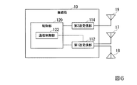
図6は、本実施形態に係る無線局10の一構成例を示すブロック図である。
無線局10は、第1送受信部112と、第2送受信部114と、送信可変ビームアンテナ17と、受信可変ビームアンテナ18と、制御部120と、を含んで構成される。
(Configuration of radio station)
Next, the configuration of the
FIG. 6 is a block diagram illustrating a configuration example of the
The
送信可変ビームアンテナ17は、第1周波数帯の電波をビームとして送信する可変ビームアンテナである。送信可変ビームアンテナ17は、上述した送信可変ビームアンテナ17−1〜17−3に相当する。
受信可変ビームアンテナ18は、第1周波数帯の電波をビームとして受信する可変ビームアンテナである。受信可変ビームアンテナ18は、上述した受信可変ビームアンテナ18−1〜18−3に相当する。
送信可変ビームアンテナ17、受信可変ビームアンテナ18は、それぞれ第1アンテナ16と同様の構成を備えていてもよい。
The transmission
The reception
The transmission
第1送受信部112は、送信可変ビームアンテナ17に送信信号を第1の周波数の電波で他の無線局10に送信させる。また、第1送受信部112は、他の無線局10から受信可変ビームアンテナ18に到来する第1の周波数の電波で搬送される受信信号を取得する。
第1送受信部112は、送信可変ビームアンテナ17、受信可変ビームアンテナ18のそれぞれについて独立にビーム方向を設定することができる。以下の説明では、送信可変ビームアンテナ17、受信可変ビームアンテナ18のそれぞれに設定するビーム方向を、送信ビーム方向、受信ビーム方向と呼ぶ。第1送受信部112は、通信制御部122から入力される方向制御信号が示す送信ビーム方向に、送信可変ビームアンテナ17が電波を送信するためのビーム方向を制御する。また、第1送受信部112は、通信制御部122から入力される方向制御信号が示す受信ビーム方向に、受信可変ビームアンテナ18が電波を受信するためのビーム方向を制御する。
The first transmission /
The first transmission /
次に、図7を参照しながら、通信制御部122が行う処理について説明する。図7は、親局である無線局10−1と子局である無線局10−2との間で行われる制御を例示する。無線局10−1の通信制御部122−1と無線局10−2の通信制御部122−2は、自局の受信可変ビームアンテナ18と相手局の送信可変ビームアンテナ17との組み合わせと、相手局の受信可変ビームアンテナ18と自局の送信可変ビームアンテナ17との組み合わせと、のそれぞれについてビーム方向探索処理を制御する。図7(b)に示すように、通信制御部122−1、122−2は、制御信号として接続要求信号、受信走査開始信号、終了信号の他、送信走査開始信号、送信走査更新信号、確認信号、送信走査終了信号を相手局との間で相互に第2送受信部114を介して送受信する。受信走査開始信号と終了信号は、受信走査に用いられる制御信号である。この受信走査の手順は、第1の実施形態で説明したビーム方向探索処理の手順を、子局である無線局10−2における受信ビーム方向と親局である無線局10−1における送信ビーム方向の組み合わせの探索に適用したものに相当する。従って、受信走査の手順については、第1の実施形態の説明を援用する。
Next, processing performed by the
他方、送信走査開始信号、送信走査更新信号、確認信号、送信走査終了信号は、送信走査に用いられる制御信号である。送信走査開始信号は、親局から子局への送信走査の開始を示す信号である。確認信号は、子局における親局からの送信走査開始信号又は送信走査更新信号の受信の確認、および親局における受信ビーム方向の走査開始を子局から親局に示すための信号である。確認信号には、子局の送信ビーム方向を示す情報が付加されてもよい。送信走査更新信号は、親局から子局への送信ビーム方向の更新の指示を示す信号である。送信走査終了信号は、親局から子局に対して送信走査の終了を示す信号である。送信走査更新信号ならびに送信走査終了信号には、その直前に行われた受信ビーム方向の走査において受信状態が最も良好な親局の受信ビーム方向と、その受信状態を示す指標値の情報が付加される。 On the other hand, the transmission scanning start signal, the transmission scanning update signal, the confirmation signal, and the transmission scanning end signal are control signals used for transmission scanning. The transmission scanning start signal is a signal indicating the start of transmission scanning from the master station to the slave station. The confirmation signal is a signal for confirming reception of the transmission scan start signal or transmission scan update signal from the master station in the slave station and indicating the scan start in the reception beam direction in the master station from the slave station to the master station. Information indicating the transmission beam direction of the slave station may be added to the confirmation signal. The transmission scan update signal is a signal indicating an instruction to update the transmission beam direction from the master station to the slave station. The transmission scanning end signal is a signal indicating the end of transmission scanning from the master station to the slave station. In the transmission scan update signal and the transmission scan end signal, information on the reception beam direction of the master station having the best reception state in the scan in the reception beam direction performed immediately before and the index value information indicating the reception state are added. The
送信走査においては、図7(b)に示すように子局である無線局10−2の通信制御部122−2は、親局である無線局10−1における各1回の受信ビーム方向の走査について、1通りの送信ビーム方向で方向探索信号を自局の送信可変ビームアンテナ17−2から放射する。このため、無線局10−2の通信制御部122−2は、方向探索信号を送信信号として、その送信ビーム方向を示す情報を方向制御信号として、第1送受信部112−2に送信する。 In the transmission scan, as shown in FIG. 7B, the communication control unit 122-2 of the radio station 10-2 that is the slave station performs the reception beam direction of each time in the radio station 10-1 that is the master station. For scanning, a direction search signal is radiated from the transmission variable beam antenna 17-2 of the local station in one transmission beam direction. For this reason, the communication control unit 122-2 of the radio station 10-2 transmits the direction search signal as a transmission signal and information indicating the transmission beam direction as a direction control signal to the first transmission / reception unit 112-2.
親局である無線局10−1の通信制御部122−1は、無線局10−2から1通りのビーム方向で方向探索信号が送信されている間、自局の受信ビーム方向が一巡するよう、受信可変ビームアンテナ18−1の受信ビーム方向を示す方向制御信号を第1送受信部112−1に順次出力する。この受信ビーム方向の走査を、無線局10−2の送信ビーム方向毎に繰り返す。その後、通信制御部122−1は、無線局10−1の受信ビーム方向と無線局10−2の送信ビーム方向の組合せ毎に測定された指標値を比較し、最も受信状態が良好な指標値に係る無線局10−1の受信ビーム方向と無線局10−2の送信ビーム方向の組み合わせを定める。通信制御部122−1は、定めた組み合わせに係る無線局10−1の受信ビーム方向を示す方向制御信号を第1送受信部112−1に出力する。従って、無線局10−1の受信可変ビームアンテナ18−1は、方向制御信号で指示された受信ビーム方向で第1周波数帯の電波を受信することができる。 The communication control unit 122-1 of the radio station 10-1 serving as the master station makes a round of the reception beam direction of its own station while the direction search signal is transmitted from the radio station 10-2 in one beam direction. Then, the direction control signal indicating the reception beam direction of the reception variable beam antenna 18-1 is sequentially output to the first transmission / reception unit 112-1. This scanning in the reception beam direction is repeated for each transmission beam direction of the radio station 10-2. Thereafter, the communication control unit 122-1 compares the index values measured for each combination of the reception beam direction of the radio station 10-1 and the transmission beam direction of the radio station 10-2, and the index value having the best reception state The combination of the reception beam direction of the radio station 10-1 and the transmission beam direction of the radio station 10-2 is determined. The communication control unit 122-1 outputs a direction control signal indicating the reception beam direction of the radio station 10-1 related to the determined combination to the first transmission / reception unit 112-1. Therefore, the reception variable beam antenna 18-1 of the radio station 10-1 can receive radio waves in the first frequency band in the reception beam direction indicated by the direction control signal.
他方、無線局10−2の通信制御部122−2は、第2送受信部114−2を介して無線局10−1から受信した送信走査更新信号ならびに送信走査終了信号に付加された受信状態を示す指標値を自局の送信ビーム方向間で比較し、最も良好な指標値に係る自局の送信ビーム方向を定める。従って、送信ビーム方向に関しても相手局の受信ビーム方向と自局の送信ビーム方向との組合せ毎に測定された指標値のうち最も受信状態が良好な指標値が特定される。無線局10−2の通信制御部122−2は、定めた送信ビーム方向を示す方向制御信号を第1送受信部112−2に出力する。従って、無線局10−2の送信可変ビームアンテナ17−2は、方向制御信号で指示される送信ビーム方向で第1周波数帯の電波を送信することができる。 On the other hand, the communication control unit 122-2 of the radio station 10-2 displays the reception state added to the transmission scan update signal and the transmission scan end signal received from the radio station 10-1 via the second transmission / reception unit 114-2. The index value shown is compared between the transmission beam directions of the own station, and the transmission beam direction of the own station related to the best index value is determined. Therefore, with respect to the transmission beam direction, the index value with the best reception state is specified among the index values measured for each combination of the reception beam direction of the partner station and the transmission beam direction of the local station. The communication control unit 122-2 of the radio station 10-2 outputs a direction control signal indicating the determined transmission beam direction to the first transmission / reception unit 112-2. Therefore, the transmission variable beam antenna 17-2 of the radio station 10-2 can transmit radio waves in the first frequency band in the transmission beam direction indicated by the direction control signal.
(ビーム方向決定手順)
次に、本実施形態に係るビーム方向決定手順の一例について説明する。
図7(b)は、本実施形態に係るビーム方向決定手順の一例を示す。図7(b)は、無線通信システム1において子局である無線局10−2から親局である無線局10−1に対して第1周波数帯として60GHz帯を用いた通信を要求する場合を例にする。
(Beam direction determination procedure)
Next, an example of a beam direction determination procedure according to the present embodiment will be described.
FIG. 7B shows an example of a beam direction determination procedure according to the present embodiment. FIG. 7B illustrates a case where the
まず、無線局10−2の通信制御部122−2は、第2送受信部114−2を介して接続要求信号を無線局10−1に送信する。
無線局10−1の通信制御部122−1は、第2送受信部114−1を介して無線局10−2から接続要求信号を受信する。この接続要求信号をトリガとしてビーム方向決定区間が開始され、無線局10−1、10−2は受信走査を行う。ここで、通信制御部122−1は、第2送受信部114−1を介して受信走査開始信号を送信し、第1送受信部112−1を介して送信可変ビームアンテナ17−1に送信ビーム方向1で方向探索信号を送信させる。
First, the communication control unit 122-2 of the wireless station 10-2 transmits a connection request signal to the wireless station 10-1 via the second transmission / reception unit 114-2.
The communication control unit 122-1 of the wireless station 10-1 receives the connection request signal from the wireless station 10-2 via the second transmission / reception unit 114-1. The beam direction determination section is started by using this connection request signal as a trigger, and the radio stations 10-1 and 10-2 perform reception scanning. Here, the communication control unit 122-1 transmits a reception scanning start signal via the second transmission / reception unit 114-1, and transmits the transmission beam direction to the transmission variable beam antenna 17-1 via the first transmission / reception unit 112-1. 1 causes a direction search signal to be transmitted.
無線局10−2の通信制御部122−2は、第1送受信部112−2を介して方向探索信号を受信し、自局の受信可変ビームアンテナ18−2についてビーム方向探索処理を行う。通信制御部122−2は、第1送受信部112−2に設定する受信ビーム方向を受信ビーム方向1、2、3、4と順次切り替え、各受信ビーム方向について受信される方向探索信号について指標値を測定する。その後、通信制御部122−2は、測定した指標値のうち、最も良好な受信状態を示す指標値に対応する無線局10−2の受信ビーム方向を特定する。通信制御部122−2は、送信ビーム方向1について無線局10−2における受信ビーム方向のビーム方向探索処理の終了を示す終了信号を、無線局10−1に第2送受信部114−2を介して送信する。この終了信号には、特定された指標値と無線局10−2の受信ビーム方向の情報が付加される。無線局10−1の通信制御部122−1は、第2送受信部114−1を介して無線局10−2から終了信号を受信する。
The communication control unit 122-2 of the radio station 10-2 receives the direction search signal via the first transmission / reception unit 112-2 and performs a beam direction search process on the reception variable beam antenna 18-2 of the local station. The communication control unit 122-2 sequentially switches the reception beam direction set in the first transmission / reception unit 112-2 to the
そして、無線局10−1の通信制御部122−1は、終了信号の受信毎に、第1送受信部112−1に設定する送信ビーム方向として送信ビーム方向2、3、4と順次切り替え、各送信ビーム方向について無線局10−2に対して受信ビーム方向のビーム方向探索処理を実行させる。無線局10−1の通信制御部122−1は、無線局10−1の各送信ビーム方向について無線局10−2から終了信号を受信する。
Then, the communication control unit 122-1 of the radio station 10-1 sequentially switches the
無線局10−2の通信制御部122−2は、無線局10−1の各送信ビーム方向について受信ビームのビーム方向探索処理が完了したと判定するとき、無線局10−1の送信ビーム方向と無線局10−2の受信ビーム方向の組み合わせ毎に測定した指標値のうち、最も良好な指標値を与える無線局10−1の送信ビーム方向と無線局10−2の受信ビーム方向の組み合わせを選択する。そして、通信制御部122−2は、選択した組み合わせに係る無線局10−2の受信方向を特定する。
他方、無線局10−1の通信制御部122−1は、無線局10−1の各送信ビーム方向についてビーム方向探索処理が完了したと判定するとき、第1送受信部112−1への方向探索信号の送信を停止し、無線局10−1の各送信ビーム方向に係る終了信号に付加された指標値のうち、最も良好な受信状態を示す指標値を特定し、その特定した指標値に対応する無線局10−1の送信ビーム方向を特定する。これにより、受信走査が終了する。
When the communication control unit 122-2 of the radio station 10-2 determines that the beam direction search processing of the reception beam is completed for each transmission beam direction of the radio station 10-1, the communication beam direction of the radio station 10-1 Of the index values measured for each combination of the reception beam directions of the radio station 10-2, a combination of the transmission beam direction of the radio station 10-1 and the reception beam direction of the radio station 10-2 that gives the best index value is selected. To do. And the communication control part 122-2 specifies the receiving direction of the radio station 10-2 which concerns on the selected combination.
On the other hand, when the communication control unit 122-1 of the radio station 10-1 determines that the beam direction search process has been completed for each transmission beam direction of the radio station 10-1, the direction search to the first transmission / reception unit 112-1 is performed. Stops signal transmission, identifies an index value indicating the best reception state among index values added to the end signal in each transmission beam direction of the radio station 10-1, and corresponds to the identified index value The direction of the transmission beam of the radio station 10-1 is specified. Thereby, the reception scanning is completed.
その後、無線局10−1の通信制御部122−1は、送信走査開始信号を、第2送受信部114−1を介して無線局10−2に送信する。この送信走査開始信号をトリガとして、無線局10−1、10−2は送信走査を開始する。
無線局10−2の通信制御部122−2は、第2送受信部114−2を介して無線局10−1から送信走査開始信号を受信する。このとき、通信制御部122−2は、第2送受信部114−2を介して無線局10−2における受信ビーム方向の走査開始の確認を示す確認信号を送信し、第1送受信部112−2を介して送信可変ビームアンテナ17−2に送信ビーム方向1で方向探索信号を送信する。よって、通信制御部122−2は、無線局10−2の送信ビーム方向1について、無線局10−1に対して受信ビーム方向のビーム方向探索処理を実行させることができる。
Thereafter, the communication control unit 122-1 of the wireless station 10-1 transmits a transmission scanning start signal to the wireless station 10-2 via the second transmission / reception unit 114-1. Using the transmission scanning start signal as a trigger, the radio stations 10-1 and 10-2 start transmission scanning.
The communication control unit 122-2 of the radio station 10-2 receives a transmission scanning start signal from the radio station 10-1 via the second transmission / reception unit 114-2. At this time, the communication control unit 122-2 transmits a confirmation signal indicating confirmation of scanning start in the reception beam direction in the radio station 10-2 via the second transmission / reception unit 114-2, and the first transmission / reception unit 112-2. The direction search signal is transmitted in the
無線局10−1の通信制御部122−1は、第2送受信部114−1を介して無線局10−2から確認信号を受信する。この確認信号をトリガとして、通信制御部122−1は、無線局10−1の受信ビーム方向についてビーム方向探索処理を行う。通信制御部122−1は、第1送受信部112−2に設定する受信ビーム方向として受信ビーム方向1、2、3、4と順次切り替え、各受信ビーム方向について受信される方向探索信号について指標値を測定する。その後、通信制御部122−1は、測定した指標値のうち、最も良好な受信状態を示す指標値に対応する無線局10−1の受信ビーム方向を特定する。通信制御部122−1は、第2送受信部114−1を介して無線局10−2に、送信走査更新信号を送信する。この送信走査更新信号には、特定された指標値と無線局10−1の受信ビーム方向の情報が付加される。無線局10−2の通信制御部122−2は、第2送受信部114−2を介して無線局10−1から送信走査更新信号を受信する。
The communication control unit 122-1 of the wireless station 10-1 receives the confirmation signal from the wireless station 10-2 via the second transmission / reception unit 114-1. Using this confirmation signal as a trigger, the communication control unit 122-1 performs a beam direction search process for the reception beam direction of the radio station 10-1. The communication control unit 122-1 sequentially switches the
他方、無線局10−2の通信制御部122−2は、送信走査更新信号の受信毎に、第1送受信部112−2に設定する送信ビーム方向を、送信ビーム方向2、3、4と順次切り替え、各送信ビーム方向について、無線局10−1に対して受信ビーム方向のビーム方向探索処理を実行させる。無線局10−1の通信制御部122−1は、実行を完了したビーム方向探索処理の回数を計数する。無線局10−1の通信制御部122−1は、実行を完了した受信ビーム方向のビーム方向探索処理の回数が4回に達したとき、無線局10−2の各送信ビーム方向について無線局10−1の受信ビーム方向のビーム方向探索処理、つまり送信走査が完了したと判定する。このとき、通信制御部122−1は、第2送受信部114−1を介して無線局10−2に、送信走査更新信号に代えて送信走査終了信号を送信する。この送信走査終了信号に特定された指標値と、直前に実行されたビーム方向探索処理で特定された無線局10−1の受信ビーム方向の情報が付加される。
On the other hand, the communication control unit 122-2 of the radio station 10-2 sequentially sets the transmission beam direction set in the first transmission / reception unit 112-2 to the
無線局10−1の通信制御部122−1は、無線局10−2の送信ビーム方向と無線局10−1の受信ビーム方向の組み合わせ毎に測定した指標値のうち、最も良好な受信状態を示す指標値を与える無線局10−2の送信ビーム方向と無線局10−1の受信ビーム方向の組み合わせを選択する。通信制御部122−1は、選択した組み合わせから無線局10−1の受信ビーム方向を特定する。通信制御部122−1は、受信走査において特定された無線局10−1の送信ビーム方向を示す方向制御信号と、送信走査において特定された無線局10−1の受信ビーム方向を示す方向制御信号とを第1送受信部112−1に出力する。よって、その送信ビーム方向、受信ビーム方向が、それぞれ無線局10−1の送信可変ビームアンテナ17−1のビーム方向、受信可変ビームアンテナ18−1のビーム方向として設定される。 The communication control unit 122-1 of the radio station 10-1 indicates the best reception state among the index values measured for each combination of the transmission beam direction of the radio station 10-2 and the reception beam direction of the radio station 10-1. A combination of the transmission beam direction of the radio station 10-2 and the reception beam direction of the radio station 10-1 that gives the index value to be shown is selected. The communication control unit 122-1 identifies the reception beam direction of the radio station 10-1 from the selected combination. The communication control unit 122-1 includes a direction control signal indicating the transmission beam direction of the radio station 10-1 specified in the reception scan, and a direction control signal indicating the reception beam direction of the radio station 10-1 specified in the transmission scan. Are output to the first transceiver 112-1. Therefore, the transmission beam direction and the reception beam direction are set as the beam direction of the transmission variable beam antenna 17-1 and the beam direction of the reception variable beam antenna 18-1, respectively.
他方、無線局10−2の通信制御部122−2は、第2送受信部114−2を介して無線局10−1から送信走査終了信号を受信するとき、無線局10−2の各送信ビーム方向について無線局10−1の受信ビーム方向のビーム方向探索処理、つまり送信走査が完了したと判定する。通信制御部122−2は、第1送受信部112−2への方向探索信号の出力を停止し、無線局10−2の各送信ビーム方向に係る送信走査更新信号又は送信走査終了信号に付加された指標値のうち、最も良好な受信状態を示す指標値に対応する無線局10−2の送信ビーム方向を特定する。通信制御部122−2は、受信走査において特定された無線局10−2の受信ビーム方向を示す方向制御信号と、送信走査において特定された無線局10−2の送信ビーム方向を示す方向制御信号とを第1送受信部112−2に出力する。よって、その受信ビーム方向、送信ビーム方向が、それぞれ無線局10−2の受信可変ビームアンテナ18−2のビーム方向、送信可変ビームアンテナ17−2のビーム方向として設定される。 On the other hand, when the communication control unit 122-2 of the wireless station 10-2 receives a transmission scanning end signal from the wireless station 10-1 via the second transmission / reception unit 114-2, each transmission beam of the wireless station 10-2 is received. For the direction, it is determined that the beam direction search process of the reception beam direction of the radio station 10-1, that is, the transmission scanning is completed. The communication control unit 122-2 stops outputting the direction search signal to the first transmission / reception unit 112-2 and is added to the transmission scan update signal or the transmission scan end signal related to each transmission beam direction of the radio station 10-2. The transmission beam direction of the radio station 10-2 corresponding to the index value indicating the best reception state is specified. The communication control unit 122-2 includes a direction control signal indicating the reception beam direction of the radio station 10-2 specified in the reception scan, and a direction control signal indicating the transmission beam direction of the radio station 10-2 specified in the transmission scan. Are output to the first transceiver 112-2. Therefore, the reception beam direction and the transmission beam direction are set as the beam direction of the reception variable beam antenna 18-2 and the beam direction of the transmission variable beam antenna 17-2 of the radio station 10-2, respectively.
その後、無線局10−1の通信制御部122−1は第1送受信部112−1を介して、無線局10−2の通信制御部122−2は第1送受信部112−2を介して、相互間で主信号の通信を開始する。
なお、本実施形態においても、2台の無線局における主信号の通信中において、他の組み合わせの2台の無線局が図7を用いて説明したビーム方向決定手順を実行し、その後、その組み合わせの2台の無線局が主信号の通信を開始してもよい(図4参照)。
Thereafter, the communication control unit 122-1 of the radio station 10-1 is sent via the first transmission / reception unit 112-1, and the communication control unit 122-2 of the radio station 10-2 is sent via the first transmission / reception unit 112-2. Start communication of main signals between each other.
In this embodiment as well, during communication of the main signal between the two wireless stations, the two wireless stations in another combination execute the beam direction determination procedure described with reference to FIG. The two radio stations may start communication of the main signal (see FIG. 4).
以上に説明したように、本実施形態に係る無線通信システム1において、少なくとも2台の無線局10のそれぞれは、第1周波数帯の電波を送信する送信可変ビームアンテナ17と、第一の周波数帯の電波を受信する受信可変ビームアンテナ18を備える。通信制御部122は、他局の送信可変ビームアンテナ17のビーム方向と自局の受信可変ビームアンテナ18のビーム方向との組み合わせ毎の伝送状態のうち、最も良好な伝送状態に係るビーム方向の組み合わせを定める。
そのため、自局から他局、他局から自局のそれぞれの伝送経路について独立に最も良好な伝送状態に係るビーム方向の組みあわせが定められ、定められたビーム方向の組み合わせを用いて第1周波数帯で自局と他局の相互間で主信号が伝送される。また、一般に波長が短い第1周波数帯の電波の伝搬状態は、アンテナの設置位置の変化に対して敏感に変化する。従って、自局から他局、他局から自局のそれぞれの信号の伝送について共通の伝送経路が用いられる場合よりも伝送状態が良好になる。
As described above, in the
Therefore, a combination of beam directions related to the best transmission state is determined independently for each transmission path from the own station to the other station and from the other station to the own station, and the first frequency is determined using the determined combination of the beam directions. The main signal is transmitted between the local station and other stations in the band. In general, the propagation state of radio waves in the first frequency band with a short wavelength changes sensitively to changes in the antenna installation position. Therefore, the transmission state is better than when a common transmission path is used for transmission of signals from the own station to the other station and from the other station to the own station.
(変形例)
以上、図面を参照してこの発明の実施形態について説明してきたが、具体的な構成や制御手順は上述のものに限られることはなく、この発明の要旨を逸脱しない範囲内において様々な設計変更等をすることが可能である。
(Modification)
The embodiment of the present invention has been described above with reference to the drawings, but the specific configuration and control procedure are not limited to those described above, and various design changes can be made without departing from the scope of the present invention. Etc. are possible.
図3、4、7に示す例では、接続要求信号をトリガとして各1個のビーム方向決定区間内において、方向探索信号を送信する無線局のビーム方向を順次変更して、各ビーム方向についてビーム方向探索処理を行い、一方の無線局のビーム方向と他方のビーム方向の全ての組み合わせのそれぞれについて受信状態を示す指標値を測定するが、これには限られない。ビーム方向探索処理は、主信号の通信中において、方向探索信号を送信する無線局のビーム方向毎に間欠的に実行されてもよい。 In the example shown in FIGS. 3, 4, and 7, the beam direction of the radio station that transmits the direction search signal is sequentially changed in each beam direction determination interval using the connection request signal as a trigger, and the beam is determined for each beam direction. The direction search process is performed, and the index value indicating the reception state is measured for each of all combinations of the beam direction of one radio station and the other beam direction, but is not limited thereto. The beam direction search process may be executed intermittently for each beam direction of the radio station that transmits the direction search signal during communication of the main signal.
つまり、図3、7に示す例において、無線局10−1の通信制御部122−1が受信走査開始信号を送信するタイミングは、必ずしも無線局10−2からの接続要求信号又は終了信号の受信直後でなくてもよい。接続要求信号又は終了信号の受信から次の受信走査開始信号の送信までの間に、所定の時間長を有する主信号通信区間が設定されてもよい。但し、通信制御部122−1は、受信走査開始信号を送信する際、その受信走査開始信号に方向探索信号の送信に係る自局のビーム方向を示す情報を付加し、主信号の送信を停止する。自局のビーム方向は、ビーム方向探索処理を未実行のビーム方向であれば、各1回のビーム方向決定について選択されるビーム方向の順序は任意であってもよい。これにより、無線局10−2の通信制御部122−2には、無線局10−1から受信した受信走査開始信号に付加された情報により方向探索信号の送信に係るビーム方向が通知される。また、この通知されたビーム方向について、無線局10−2の通信制御部122−2は、ビーム方向探索処理の実行後、無線局10−1に終了信号を送信する。そのため、無線局10−1の通信制御部122−1と無線局10−2の通信制御部122−2との間で、ビーム方向探索処理の実行済の方向探索信号の送信に係るビーム方向の情報が共有される。 That is, in the example illustrated in FIGS. 3 and 7, the timing at which the communication control unit 122-1 of the wireless station 10-1 transmits the reception scanning start signal is not necessarily the reception of the connection request signal or the end signal from the wireless station 10-2. It does not have to be immediately after. A main signal communication section having a predetermined time length may be set between the reception of the connection request signal or the end signal and the transmission of the next reception scanning start signal. However, when transmitting the reception scanning start signal, the communication control unit 122-1 adds information indicating the beam direction of the local station related to the transmission of the direction search signal to the reception scanning start signal, and stops the transmission of the main signal. To do. As long as the beam direction of the own station is a beam direction in which the beam direction search process has not been executed, the order of the beam directions selected for each one beam direction determination may be arbitrary. Thus, the beam direction related to the transmission of the direction search signal is notified to the communication control unit 122-2 of the radio station 10-2 by the information added to the reception scanning start signal received from the radio station 10-1. Further, for this notified beam direction, the communication control unit 122-2 of the radio station 10-2 transmits an end signal to the radio station 10-1 after executing the beam direction search process. Therefore, between the communication control unit 122-1 of the radio station 10-1 and the communication control unit 122-2 of the radio station 10-2, the beam direction related to the transmission of the direction search signal for which the beam direction search process has been performed is transmitted. Information is shared.
また、図7に示す例において、無線局10−2の通信制御部122−2が確認信号を送信するタイミングは、無線局10−1からの送信走査開始信号又は送信走査更新信号の受信直後でなくてもよい。送信走査開始信号又は送信走査更新信号の受信から次の確認信号の送信までの間に、所定の時間長を有する主信号通信区間が設定されてもよい。但し、通信制御部122−2は、確認信号を送信する際、その確認信号に方向探索信号の送信に係る自局の送信ビーム方向を示す情報を付加し、主信号の送信を停止する。自局の送信ビーム方向として、ビーム方向探索処理を未実行の送信ビーム方向であれば、1回の送信走査に係るビーム方向決定において選択される送信ビーム方向の順序は任意であってもよい。これにより、無線局10−1の通信制御部122−1には、無線局10−2から受信した確認信号に付加された情報をもって方向探索信号の送信に係る送信ビーム方向が通知される。また、この通知された送信ビーム方向について、無線局10−1の通信制御部122−1は、ビーム方向探索処理の実行後、無線局10−2に送信走査更新信号又は送信走査終了信号を送信する。そのため、無線局10−1の通信制御部122−1と無線局10−2の通信制御部122−2との間で、ビーム方向探索処理の実行済の方向探索信号の送信に係る送信ビーム方向の情報が共有される。そのため、ビーム方向探索処理の実行に係るビーム方向の順序や個数が、必ずしも事前に無線局10−1、10−2間で設定されていなくてもよい。 In the example illustrated in FIG. 7, the timing at which the communication control unit 122-2 of the wireless station 10-2 transmits the confirmation signal is immediately after reception of the transmission scanning start signal or the transmission scanning update signal from the wireless station 10-1. It does not have to be. A main signal communication section having a predetermined time length may be set between the reception of the transmission scanning start signal or the transmission scanning update signal and the transmission of the next confirmation signal. However, when transmitting the confirmation signal, the communication control unit 122-2 adds information indicating the transmission beam direction of the own station related to the transmission of the direction search signal to the confirmation signal, and stops the transmission of the main signal. As long as the transmission beam direction of the own station is the transmission beam direction for which beam direction search processing has not been executed, the order of the transmission beam directions selected in the beam direction determination related to one transmission scan may be arbitrary. Thereby, the communication control unit 122-1 of the radio station 10-1 is notified of the transmission beam direction related to the transmission of the direction search signal with information added to the confirmation signal received from the radio station 10-2. Further, for this notified transmission beam direction, the communication control unit 122-1 of the radio station 10-1 transmits a transmission scan update signal or a transmission scan end signal to the radio station 10-2 after executing the beam direction search process. To do. Therefore, the transmission beam direction related to the transmission of the direction search signal for which the beam direction search process has been performed between the communication control unit 122-1 of the radio station 10-1 and the communication control unit 122-2 of the radio station 10-2. Information is shared. Therefore, the order and the number of beam directions related to the execution of the beam direction search process do not necessarily have to be set between the radio stations 10-1 and 10-2 in advance.
なお、無線局10−1の通信制御部122−1が受信走査開始信号を送信するタイミング、又は無線局10−2の通信制御部122−2が確認信号を送信するタイミングを、送受信に係る主信号の通信速度が所定の通信速度よりも低いときに定めてもよい。所定の通信速度は、第1周波数帯の帯域幅のうち主信号の送受信に割り当てられた帯域幅で可能とする通信速度よりも低ければよい。 Note that the timing at which the communication control unit 122-1 of the radio station 10-1 transmits a reception scanning start signal or the timing at which the communication control unit 122-2 of the radio station 10-2 transmits a confirmation signal is mainly related to transmission / reception. It may be determined when the signal communication speed is lower than a predetermined communication speed. The predetermined communication speed only needs to be lower than the communication speed enabled by the bandwidth allocated to transmission / reception of the main signal in the bandwidth of the first frequency band.
また、主信号が第1周波数帯で伝送され、第2周波数帯で主信号とは独立にビーム方向の制御に要する情報が伝送されるため、無線局10−1の通信制御部122−1は、通信中に自局あるいは相手局のビーム方向を修正することで、より良好な伝送状態が得られるビーム方向を探索してもよい。自局のビーム方向を修正する際、無線局10−1の通信制御部122−1は、その時点における第1アンテナ16−1のビーム方向から所定の微小な角度(例えば、0.5°〜2°)ずつ変化させる。通信制御部122−1は、変化後のビーム方向毎に受信状態を示す指標値を相手局である無線局10−2から第2送受信部114−1を介して取得してもよい。そして、通信制御部122−1は、取得した指標値が最も良好な受信状態を示すビーム方向を特定し、特定したビーム方向を示す方向制御信号を第1送受信部112−1に出力することで、第1アンテナ16−1にその方向で信号を送信させる。 In addition, since the main signal is transmitted in the first frequency band and information necessary for beam direction control is transmitted in the second frequency band independently of the main signal, the communication control unit 122-1 of the radio station 10-1 The beam direction in which a better transmission state can be obtained may be searched by correcting the beam direction of the own station or the partner station during communication. When correcting the beam direction of the own station, the communication control unit 122-1 of the radio station 10-1 determines a predetermined minute angle (for example, 0.5 ° to 5 °) from the beam direction of the first antenna 16-1 at that time. 2 °). The communication control unit 122-1 may acquire an index value indicating a reception state for each beam direction after the change from the radio station 10-2 that is the counterpart station via the second transmission / reception unit 114-1. And the communication control part 122-1 specifies the beam direction which shows the reception state with the best acquired index value, and outputs the direction control signal which shows the specified beam direction to the 1st transmission / reception part 112-1. The first antenna 16-1 is caused to transmit a signal in that direction.
自局のビーム方向毎の指標値を取得する際、無線局10−1と無線局10−2は、次の処理を行う。
無線局10−1の通信制御部122−1は、変化後の自局のビーム方向を示す方向制御信号を第1送受信部112−1に出力し、無線局10−1の第1アンテナ16−1にその方向で主信号を送信させる。通信制御部122−1は、そのビーム方向に係る受信状態要求信号を第2送受信部114−1を介して無線局10−2に送信する。
無線局10−2の通信制御部122−2は、無線局10−1から第2送受信部114−2を介して受信状態要求信号を受信し、受信した受信状態要求信号が示すビーム方向を特定する。通信制御部122−2は、第1送受信部112−2を介して受信する主信号について受信状態を示す指標値を測定し、測定した指標値を示す受信状態報告信号を第2送受信部114−2を介して無線局10−1に送信する。
無線局10−1の通信制御部122−1は、第2送受信部114−2を介して無線局10−2から受信した受信状態報告信号が示す指標値を、そのビーム方向に係る受信状態を示す指標値として特定する。
When acquiring the index value for each beam direction of the own station, the radio station 10-1 and the radio station 10-2 perform the following processing.
The communication control unit 122-1 of the wireless station 10-1 outputs a direction control signal indicating the beam direction of the own station after the change to the first transmitting / receiving unit 112-1, and the first antenna 16- of the wireless station 10-1. 1 causes the main signal to be transmitted in that direction. The communication control unit 122-1 transmits a reception state request signal related to the beam direction to the radio station 10-2 via the second transmission / reception unit 114-1.
The communication control unit 122-2 of the wireless station 10-2 receives the reception state request signal from the wireless station 10-1 via the second transmission / reception unit 114-2, and specifies the beam direction indicated by the received reception state request signal. To do. The communication control unit 122-2 measures an index value indicating the reception state of the main signal received via the first transmission / reception unit 112-2, and sends a reception state report signal indicating the measured index value to the second transmission /
The communication control unit 122-1 of the radio station 10-1 indicates the index value indicated by the reception status report signal received from the radio station 10-2 via the second transmission / reception unit 114-2 and the reception status related to the beam direction. It is specified as the indicated index value.
相手局のビーム方向を修正する際、無線局10−1の通信制御部122−1は、第2送受信部114−1を介して相手局である無線局10−2の第1アンテナ16−2のビーム方向を微小な角度ずつ変化させ、変化後のビーム方向毎に受信状態を示す指標値を第1送受信部112−1から取得する。この場合、通信制御部122−1は、取得した指標値が最も良好な受信状態を示すビーム方向を特定し、特定したビーム方向を第2送受信部114−1を介して無線局10−2の通信制御部122−2に伝達する。通信制御部122−2は、特定したビーム方向を示す方向制御信号を第1送受信部112−2に出力することで、第1アンテナ16−2にその方向で信号を送信させる。 When correcting the beam direction of the counterpart station, the communication control unit 122-1 of the radio station 10-1 receives the first antenna 16-2 of the radio station 10-2 that is the counterpart station via the second transmission / reception unit 114-1. The beam direction is changed by a minute angle, and an index value indicating the reception state is obtained from the first transmission / reception unit 112-1 for each changed beam direction. In this case, the communication control unit 122-1 identifies the beam direction that indicates the reception state in which the acquired index value is the best, and the identified beam direction is transmitted to the radio station 10-2 via the second transmission / reception unit 114-1. This is transmitted to the communication control unit 122-2. The communication control unit 122-2 outputs a direction control signal indicating the specified beam direction to the first transmission / reception unit 112-2, thereby causing the first antenna 16-2 to transmit a signal in that direction.
相手局のビーム方向毎の指標値を取得する際、無線局10−1と無線局10−2は、次の処理を行う。
無線局10−1の通信制御部122−1は、相手局である無線局10−2の変化後のビーム方向の情報を第2送受信部114−1を介して無線局10−2に送信する。
無線局10−2の通信制御部122−2は、無線局10−1から第2送受信部114−2を介してそのビーム方向の情報を受信し、受信したビーム方向を示す方向制御信号を第1送受信部112−2に出力し、無線局10−2の第1アンテナ16−2にその方向で信号を送信させる。
無線局10−1の通信制御部122−1は、第1送受信部112−1を介して受信する主信号について受信状態を示す指標値を測定する。
When acquiring the index value for each beam direction of the counterpart station, the radio station 10-1 and the radio station 10-2 perform the following processing.
The communication control unit 122-1 of the radio station 10-1 transmits the information on the beam direction after the change of the radio station 10-2 that is the counterpart station to the radio station 10-2 via the second transmission / reception unit 114-1. .
The communication control unit 122-2 of the radio station 10-2 receives the information on the beam direction from the radio station 10-1 via the second transmission / reception unit 114-2, and receives a direction control signal indicating the received beam direction. 1 is output to the transmission / reception unit 112-2, and the signal is transmitted in the direction to the first antenna 16-2 of the radio station 10-2.
The communication control unit 122-1 of the radio station 10-1 measures an index value indicating a reception state for the main signal received via the first transmission / reception unit 112-1.
また、上述した実施形態では、第1周波数帯が単一の周波数帯で構成される場合を例にしたが、これには限られない。第1周波数帯は、複数の周波数帯で構成され、これら複数の周波数帯を用いて無線局間で各種の信号が送受信されてもよい。送受信対象の信号は、方向探索信号、主信号のいずれであってもよい。
第1の実施形態では、これらの複数の周波数帯が各無線局10について1個の第1アンテナ16で共用され、周波数分割複信(FDD:Frequency Division Duplex)方式が適用されてもよい。例えば、無線局10−1の通信制御部122−1は、第1送受信部112−1に対して無線局10−2への信号の送信に用いる周波数帯として70GHz帯を割り当てる。その場合、無線局10−2の通信制御部122−2は、第1送受信部112−2に対して無線局10−1からの信号の受信に用いる周波数帯として70GHz帯を割り当てる。これに対し、無線局10−2の通信制御部122−2は、第1送受信部112−2に対して無線局10−2への信号の送信に用いる周波数帯として80GHz帯を割り当てる。その場合、無線局10−1の通信制御部122−1は、第1送受信部112−1に対して無線局10−2からの信号の受信に用いる周波数帯として80GHz帯を割り当てる。
In the above-described embodiment, the first frequency band is configured as a single frequency band. However, the present invention is not limited to this. The first frequency band is composed of a plurality of frequency bands, and various signals may be transmitted and received between wireless stations using the plurality of frequency bands. The signal to be transmitted / received may be either a direction search signal or a main signal.
In the first embodiment, the plurality of frequency bands may be shared by one
第2の実施形態では、複数の周波数帯が各無線局10について、その送受信の区別に応じて送信可変ビームアンテナ17、受信可変ビームアンテナ18間で割り当てられればよい。例えば、無線局10−1の通信制御部122−1は、第1送受信部112−1に対して無線局10−2への信号の送信に用いる周波数帯として70GHz帯を割り当て、その信号を搬送する電波を送信可変ビームアンテナ17−1に送信させる。その場合、無線局10−2の通信制御部122−2は、第1送受信部112−2に対して無線局10−1からの信号の受信に用いる周波数帯として70GHz帯を割り当て、その信号を搬送する電波を受信可変ビームアンテナ18−2に受信させる。これに対し、無線局10−2の通信制御部122−2は、第1送受信部112−2に対して無線局10−1への信号の送信に用いる周波数帯として80GHz帯を割り当て、その信号を搬送する電波を送信可変ビームアンテナ17−2に送信させる。その場合、無線局10−1の通信制御部122−1は、第1送受信部112−1に対して無線局10−2からの信号の受信に用いる周波数帯として80GHz帯を割り当て、その信号を搬送する電波を受信可変ビームアンテナ18−1に受信させる。
In the second embodiment, a plurality of frequency bands may be allocated between the transmission
図3、7に示す例では、主に無線局10−2が無線局10−1に対して接続を要求するときに、図4に示す例では、無線局10−3が無線局10−1に対して接続を要求するときに、ビーム方向決定手順を開始する場合について説明した。ビーム方向決定手順を開始するタイミングは、これには限られない。そのタイミングは、通信中の主信号の伝送状態が、所定の伝送状態よりも劣るときであってもよい。所定の伝送状態よりも劣るときには、信号の送受信ができずに接続が中断された場合も含まれる。
より具体的には、無線局10−2の通信制御部122−2は、第1送受信部112−2を介して主信号を無線局10−1から受信するとき、受信した主信号について所定の周期毎にその受信状態を示す指標値を測定する。通信制御部122−2は、測定した指標値が示す受信状態が所定の閾値が示す受信状態よりも劣るとき、第2送受信部114−2を介して相手局である無線局10−1に接続要求信号を送信する。無線局10−1の通信制御部122−1は、無線局10−2から受信した接続要求信号をトリガとして無線局10−2との間でビーム方向の制御を開始することができる。
3 and 7, when the radio station 10-2 mainly requests connection to the radio station 10-1, in the example shown in FIG. 4, the radio station 10-3 is the radio station 10-1. The case where the beam direction determination procedure is started when the connection is requested to has been described. The timing for starting the beam direction determination procedure is not limited to this. The timing may be when the transmission state of the main signal during communication is inferior to a predetermined transmission state. When it is inferior to a predetermined transmission state, the case where the connection is interrupted because the signal cannot be transmitted and received is also included.
More specifically, when the communication control unit 122-2 of the radio station 10-2 receives a main signal from the radio station 10-1 via the first transmission / reception unit 112-2, the communication control unit 122-2 receives a predetermined signal for the received main signal. An index value indicating the reception state is measured for each period. When the reception state indicated by the measured index value is inferior to the reception state indicated by the predetermined threshold, the communication control unit 122-2 is connected to the radio station 10-1 that is the partner station via the second transmission / reception unit 114-2. Send a request signal. The communication control unit 122-1 of the radio station 10-1 can start beam direction control with the radio station 10-2 using the connection request signal received from the radio station 10-2 as a trigger.
その他、上述した無線局10を構成する各機能部の名称、制御信号の名称は、任意に定められてもよく、本発明の技術的範囲を限定するものではない。また、無線通信システム1を構成する無線局10の数は、3個に限られず2個又は4個以上であってもよい。それらの無線局10のうち、第1周波数帯と第2周波数帯を用いて通信可能とする無線局10は少なくとも2個以上あればよい。また、可変ビームアンテナ16、又は送信可変ビームアンテナ17ならびに受信可変ビームアンテナ18を備える無線局10は、少なくとも1個あればよい。それ以外の全ての無線局10が有するビームアンテナのビーム方向が固定されている場合には、その少なくとも1個の無線局10は、移動可能な移動局よりも、位置が固定されている固定局であることが望ましい。また、各無線局のビーム方向の個数は、4個に限られず、2個、3個又は5個以上であってもよい。また、各1回のビーム方向決定手順におけるビーム方向の順序は、必ずしもその符号の順序でなくてもよく、任意に設定されてもよい。
In addition, the names of the functional units constituting the above-described
1…無線通信システム、10…無線局、12…60GHz帯送受信機、14…920MHz帯送受信機、16…第1アンテナ(可変ビームアンテナ)、17…送信可変ビームアンテナ、18…受信可変ビームアンテナ、19…第2アンテナ(無指向性アンテナ)、112…第1送受信部、114…第2送受信部、120…制御部、122…通信制御部
DESCRIPTION OF
Claims (6)
前記複数の無線局のうち少なくとも2つの無線局のそれぞれは、
第1周波数帯の電波を伝送する第1アンテナと、
前記第1周波数帯よりも周波数が低い第2周波数帯で電波を伝送する第2アンテナと、
前記第1周波数帯で主信号を送受信する第1送受信部と、
前記第2周波数帯で制御信号を送受信する第2送受信部と、
を備え、
前記少なくとも2つの無線局のうち、少なくとも1つの無線局は、
前記第1アンテナとしてビーム方向が可変である可変ビームアンテナと、
前記第2アンテナとして前記ビーム方向の可変範囲以上の放射範囲を有する広角アンテナと、
前記制御信号に基づいて前記可変ビームアンテナのビーム方向を制御する制御部と、
を備える
無線通信システム。 A wireless communication system comprising a plurality of wireless stations,
Each of at least two of the plurality of wireless stations is
A first antenna for transmitting radio waves in a first frequency band;
A second antenna for transmitting radio waves in a second frequency band having a frequency lower than that of the first frequency band;
A first transceiver for transmitting and receiving a main signal in the first frequency band;
A second transceiver for transmitting and receiving a control signal in the second frequency band;
With
Of the at least two radio stations, at least one radio station is:
A variable beam antenna having a variable beam direction as the first antenna;
A wide-angle antenna having a radiation range greater than or equal to the variable range of the beam direction as the second antenna;
A control unit for controlling a beam direction of the variable beam antenna based on the control signal;
A wireless communication system.
前記制御信号として前記ビーム方向の探索に係る情報を他局から受信するとき、自局の可変ビームアンテナのビーム方向を探索する
ことを特徴とする請求項1に記載の無線通信システム。 The controller is
2. The wireless communication system according to claim 1, wherein when information related to the search of the beam direction is received from another station as the control signal, the beam direction of the variable beam antenna of the local station is searched.
請求項1または請求項2に記載の無線通信システム。 The control unit measures the transmission state of the main signal, and transmits the information related to the search for the beam direction to the other station as the control signal when the transmission state is inferior to a predetermined transmission state. The wireless communication system according to claim 2.
前記可変ビームアンテナとして、前記第1周波数帯の電波を送信する送信可変ビームアンテナと、前記第1周波数帯の電波を受信する受信可変ビームアンテナとを備え、
前記制御部は、他局の前記送信可変ビームアンテナのビーム方向と自局の前記受信可変ビームアンテナのビーム方向を独立に定める
請求項1から請求項3のいずれか一項に記載の無線通信システム。 The at least one radio station is
The variable beam antenna includes a transmission variable beam antenna that transmits radio waves in the first frequency band, and a reception variable beam antenna that receives radio waves in the first frequency band,
The wireless communication system according to any one of claims 1 to 3, wherein the control unit independently determines a beam direction of the transmission variable beam antenna of another station and a beam direction of the reception variable beam antenna of the local station. .
ことを特徴とする請求項1から請求項4のいずれか一項に記載の無線通信システム。 The wireless communication system according to any one of claims 1 to 4, wherein a transmission rate in the second frequency band is lower than a transmission rate in the first frequency band.
前記複数のうち、少なくとも12つの無線局のそれぞれは、
第1周波数帯の電波を伝送する第1アンテナと、
第1周波数帯よりも周波数が低い第2周波数帯で電波を伝送する第2アンテナと、
を備え、
前記第1周波数帯で主信号を送受信する第1送受信過程と、
前記第2周波数帯で制御信号を送受信する第2送受信過程と、
を有し、
前記少なくとも2つの無線局のうち、少なくとも1つの無線局は、 前記第1アンテナとしてビーム方向が可変である可変ビームアンテナと、
前記第2アンテナとして前記ビーム方向の可変範囲以上の放射範囲を有する広角アンテナと、
を備え、
前記制御信号に基づいて前記可変ビームアンテナのビーム方向を制御する制御過程、
を有する無線通信方法。 A wireless communication method in a wireless communication system comprising a plurality of wireless stations,
Each of the at least 12 radio stations of the plurality is
A first antenna for transmitting radio waves in a first frequency band;
A second antenna for transmitting radio waves in a second frequency band having a frequency lower than that of the first frequency band;
With
A first transmission / reception process of transmitting / receiving a main signal in the first frequency band;
A second transmission / reception process of transmitting / receiving a control signal in the second frequency band;
Have
Of the at least two radio stations, at least one radio station includes a variable beam antenna having a variable beam direction as the first antenna;
A wide-angle antenna having a radiation range greater than or equal to the variable range of the beam direction as the second antenna;
With
A control process for controlling a beam direction of the variable beam antenna based on the control signal;
A wireless communication method.
Priority Applications (6)
| Application Number | Priority Date | Filing Date | Title |
|---|---|---|---|
| JP2017027041A JP2018133733A (en) | 2017-02-16 | 2017-02-16 | Radio communication system and radio communication method |
| CA3053636A CA3053636A1 (en) | 2017-02-16 | 2017-12-18 | Wireless communication system and wireless communication method |
| US16/486,206 US10686515B2 (en) | 2017-02-16 | 2017-12-18 | Wireless communication system and wireless communication method |
| PCT/JP2017/045295 WO2018150712A1 (en) | 2017-02-16 | 2017-12-18 | Wireless communication system and wireless communication method |
| EP17896551.3A EP3584954A4 (en) | 2017-02-16 | 2017-12-18 | Wireless communication system and wireless communication method |
| JP2022007418A JP7096452B2 (en) | 2017-02-16 | 2022-01-20 | Wireless communication system and wireless communication method |
Applications Claiming Priority (1)
| Application Number | Priority Date | Filing Date | Title |
|---|---|---|---|
| JP2017027041A JP2018133733A (en) | 2017-02-16 | 2017-02-16 | Radio communication system and radio communication method |
Related Child Applications (1)
| Application Number | Title | Priority Date | Filing Date |
|---|---|---|---|
| JP2022007418A Division JP7096452B2 (en) | 2017-02-16 | 2022-01-20 | Wireless communication system and wireless communication method |
Publications (1)
| Publication Number | Publication Date |
|---|---|
| JP2018133733A true JP2018133733A (en) | 2018-08-23 |
Family
ID=63170280
Family Applications (1)
| Application Number | Title | Priority Date | Filing Date |
|---|---|---|---|
| JP2017027041A Pending JP2018133733A (en) | 2017-02-16 | 2017-02-16 | Radio communication system and radio communication method |
Country Status (5)
| Country | Link |
|---|---|
| US (1) | US10686515B2 (en) |
| EP (1) | EP3584954A4 (en) |
| JP (1) | JP2018133733A (en) |
| CA (1) | CA3053636A1 (en) |
| WO (1) | WO2018150712A1 (en) |
Families Citing this family (1)
| Publication number | Priority date | Publication date | Assignee | Title |
|---|---|---|---|---|
| WO2020046062A1 (en) * | 2018-08-31 | 2020-03-05 | 엘지전자 주식회사 | Method for performing beam sweeping by terminal supporting sidelink in wireless communication system, and terminal therefor |
Citations (5)
| Publication number | Priority date | Publication date | Assignee | Title |
|---|---|---|---|---|
| JP2008219503A (en) * | 2007-03-05 | 2008-09-18 | Omron Corp | Tag communication device and tag communication system |
| WO2011055536A1 (en) * | 2009-11-04 | 2011-05-12 | 日本電気株式会社 | Control method for wireless communication system, wireless communication system, and wireless communication device |
| US20140148107A1 (en) * | 2012-11-28 | 2014-05-29 | Alexander Maltsev | Using Multiple Frequency Bands With Beamforming Assistance in a Wireless Network |
| US20140206406A1 (en) * | 2013-01-23 | 2014-07-24 | Carlos Cordeiro | Apparatus, system and method of establishing a wireless beamformed link |
| JP2016528830A (en) * | 2013-08-09 | 2016-09-15 | クゥアルコム・インコーポレイテッドQualcomm Incorporated | Method and apparatus for management of high frequency communications in a low frequency wireless network |
Family Cites Families (6)
| Publication number | Priority date | Publication date | Assignee | Title |
|---|---|---|---|---|
| KR100452536B1 (en) * | 2000-10-02 | 2004-10-12 | 가부시키가이샤 엔.티.티.도코모 | Mobile communication base station equipment |
| US6750810B2 (en) * | 2001-12-18 | 2004-06-15 | Hitachi, Ltd. | Monopulse radar system |
| US20050156780A1 (en) * | 2004-01-16 | 2005-07-21 | Ghz Tr Corporation | Methods and apparatus for automotive radar sensors |
| TWI595762B (en) | 2011-12-08 | 2017-08-11 | 內數位專利控股公司 | Method and apparatus for a millimeter wave communication system |
| US9572106B2 (en) | 2014-10-31 | 2017-02-14 | Qualcomm Incorporated | Dynamic bandwidth switching for reducing power consumption in wireless communication devices |
| TWI682991B (en) | 2015-07-21 | 2020-01-21 | 日商日本化藥股份有限公司 | Liquid crystal sealing agent and liquid crystal display cell using the same |
-
2017
- 2017-02-16 JP JP2017027041A patent/JP2018133733A/en active Pending
- 2017-12-18 CA CA3053636A patent/CA3053636A1/en not_active Abandoned
- 2017-12-18 WO PCT/JP2017/045295 patent/WO2018150712A1/en unknown
- 2017-12-18 US US16/486,206 patent/US10686515B2/en active Active
- 2017-12-18 EP EP17896551.3A patent/EP3584954A4/en active Pending
Patent Citations (5)
| Publication number | Priority date | Publication date | Assignee | Title |
|---|---|---|---|---|
| JP2008219503A (en) * | 2007-03-05 | 2008-09-18 | Omron Corp | Tag communication device and tag communication system |
| WO2011055536A1 (en) * | 2009-11-04 | 2011-05-12 | 日本電気株式会社 | Control method for wireless communication system, wireless communication system, and wireless communication device |
| US20140148107A1 (en) * | 2012-11-28 | 2014-05-29 | Alexander Maltsev | Using Multiple Frequency Bands With Beamforming Assistance in a Wireless Network |
| US20140206406A1 (en) * | 2013-01-23 | 2014-07-24 | Carlos Cordeiro | Apparatus, system and method of establishing a wireless beamformed link |
| JP2016528830A (en) * | 2013-08-09 | 2016-09-15 | クゥアルコム・インコーポレイテッドQualcomm Incorporated | Method and apparatus for management of high frequency communications in a low frequency wireless network |
Also Published As
| Publication number | Publication date |
|---|---|
| US20200059291A1 (en) | 2020-02-20 |
| WO2018150712A1 (en) | 2018-08-23 |
| EP3584954A4 (en) | 2020-10-21 |
| EP3584954A1 (en) | 2019-12-25 |
| US10686515B2 (en) | 2020-06-16 |
| CA3053636A1 (en) | 2018-08-23 |
Similar Documents
| Publication | Publication Date | Title |
|---|---|---|
| US11336347B2 (en) | Beam management techniques for beam calibration | |
| US9270355B2 (en) | Control method of radio communication system, radio communication system, and radio communication apparatus | |
| JP6182582B2 (en) | Scheduling method and millimeter wave radio communication station | |
| US9184821B2 (en) | Control method of radio communication system, radio communication system, and radio communication apparatus | |
| JP5633559B2 (en) | Wireless communication system control method, wireless communication system, and wireless communication apparatus | |
| JP2010192946A (en) | Communication device, communication control method and communication system | |
| JP5804407B2 (en) | Wireless device | |
| EP3322105B1 (en) | Beam training method and device for multi-user scenario | |
| US20170272959A1 (en) | Virtual base station apparatus and communication method | |
| EP3278467B1 (en) | Access node, user node and method for determining at least one beamforming parameter | |
| JP2017152830A (en) | Wireless communication system, transmitting device, receiving device, and communication method | |
| WO2018150712A1 (en) | Wireless communication system and wireless communication method | |
| JP7096452B2 (en) | Wireless communication system and wireless communication method | |
| JP2012191281A (en) | Radio communication device |
Legal Events
| Date | Code | Title | Description |
|---|---|---|---|
| RD03 | Notification of appointment of power of attorney |
Free format text: JAPANESE INTERMEDIATE CODE: A7423 Effective date: 20181019 |
|
| A621 | Written request for application examination |
Free format text: JAPANESE INTERMEDIATE CODE: A621 Effective date: 20191122 |
|
| A131 | Notification of reasons for refusal |
Free format text: JAPANESE INTERMEDIATE CODE: A131 Effective date: 20210119 |
|
| A521 | Request for written amendment filed |
Free format text: JAPANESE INTERMEDIATE CODE: A523 Effective date: 20210218 |
|
| A131 | Notification of reasons for refusal |
Free format text: JAPANESE INTERMEDIATE CODE: A131 Effective date: 20210803 |
|
| A521 | Request for written amendment filed |
Free format text: JAPANESE INTERMEDIATE CODE: A523 Effective date: 20210817 |
|
| A02 | Decision of refusal |
Free format text: JAPANESE INTERMEDIATE CODE: A02 Effective date: 20211221 |