TECHNICAL FIELD
The present invention relates to a flow rate
measurement apparatus for measuring a flow rate of fluid,
such as gas or the like.
BACKGROUND ART
There are many known methods for measuring the flow
rate of fluids, such as gases, liquids, etc. Especially,
reliable flow velocity/flow rate measurement apparatuses
which utilize ultrasonic waves have been remarkably
developed thanks to progress in techniques of electronics.
The flow velocity/flow rate measurement apparatuses which
utilize ultrasonic waves can be employed in various
application fields, such as a meter for fuel gas, an
industrial measurement device, a blood-flow meter for
medical use, measurement of flow velocity in the ocean or
atmosphere, etc. Such flow velocity/flow rate measurement
apparatuses can directly utilize ultrasonic waves in some
cases, and in other cases, can be utilized as a detecting
section of a measurement apparatus which operates based on
other measurement principles and which indirectly utilize
ultrasonic waves.
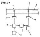
As shown in Figure 21, a conventional ultrasonic
flow-velocity meter includes: an ultrasonic transmitting
transducer 2 which is placed in a measurement path 1 through
which fluid flows; a transmission circuit 3 for driving the
ultrasonic transmitting transducer 2; a controller 5 for
simultaneously transmitting a vibration start signal from
the transmission circuit 3 and for starting a timer 4; an
ultrasonic receiving transducer 6 which is placed upstream
or downstream of the ultrasonic transducer 2 and which
receives ultrasonic waves emitted by the ultrasonic
transducer 2; an amplifier 7 for amplifying a received
signal from the ultrasonic receiving transducer 6; and a
comparator 9 for comparing the signal output from the
amplifier 7 and a reference signal output from a reference
signal generating section 8 and for stopping the timer 4
when the relationship of the magnitudes between these
signals is inverted. This conventional ultrasonic flow-velocity
meter is structured such that the flow velocity
of the measured fluid is measured based on a time measured
by the timer 4.
In the above ultrasonic flow-velocity meter, in
response to a start signal from the controller 5, the
transmission circuit 3 outputs a pulse during a
predetermined time so as to drive the ultrasonic
transducer 2. An ultrasonic wave emitted by the ultrasonic
transducer 2 propagates through the measured fluid and is
then received by the ultrasonic receiving transducer 6
after a lapse of time t. This received signal is compared
with a reference signal by the comparator 9. When the
relationship in voltage between the received signal and the
reference signal is inverted, a stop signal is transmitted
to the timer 4. In response to this stop signal, the timer 4
stops. The flow velocity v of the measured fluid is
calculated by assigning an output value, obtained for time t,
in expression (1):
v = (L/(t-a))-c
where L denotes the effective distance along a flowing
direction between the ultrasonic wave transmitter and the
ultrasonic wave receiver, c denotes a sonic velocity, v
denotes a flow velocity of the measured fluid, a denotes
a delay time from when the signal is received to when the
output of the comparator 9 is inverted. A direction from
the ultrasonic transducer to the ultrasonic receiving
transducer is referred to as the positive direction.
Alternatively, the ultrasonic transducer 2 and the
ultrasonic receiving transducer 6 are switched, and a
propagation time t1 from upstream to downstream and a
propagation time t2 from downstream to upstream are measured
so as to obtain a flow velocity v based on expression (2):
v = L/2(1/t1-1/t2)+a
According to this method, the velocity of a flowing
fluid can be measured independent from influences caused
by a change in sonic velocity due to changes in temperature.
Thus, this method has been widely used in measurement of
flow velocity, flow rate, distance, etc.
Not only flow velocity/flow rate measurement
apparatuses which utilize ultrasonic waves but also general
flow velocity/flow rate measurement apparatuses that use
many sensors, such as a flow rate sensor, a resistance sensor,
a temperature sensor, a voltage sensor, etc. These sensors,
which transmit electric signals, are influenced by external
conditions such that the sensitivity thereof is changed in
some cases. Thus, a flow rate measurement apparatus used
in a meter for fuel gas or the like is required to measure
even a very small change in flow rate, e.g., 3 liters/hour.
In order to correctly detect such a very small change, a
measurement apparatus must be structured such that it can
perform zero-point correction for measurements.
In view of the above, a technique disclosed in
Japanese Laid-Open Publication No. 8-271307 is a gas
flow-rate meter which determines, at a predetermined time
interval, whether or not performing zero-point correction
is appropriate and performs zero-point correction based on
such a determination. This is regarded as a very useful
technique in the field of gas equipment.
However, when the above conventional structure is
applied to a flow rate measurement apparatus for fuel gas
such as propane gas, the flow rate of fluid widely varies
in a flow path; for example, change in flow rate is very
small in some cases, but change in flow rate is several
ten-thousand liters per hour in other cases. Accordingly,
the input waveform of a received signal widely varies
according to the flow velocity. Thus, it is difficult to
measure the flow rate without adjusting reception
sensitivity.
In general, a sensor which transmits an electric
signal is influenced by external conditions such that the
sensitivity thereof may be changed. Thus, a flow rate
measurement apparatus used in a meter for fuel gas or the
like is required to measure even a very small change in flow
rate, e.g., 3 liters/hour. In order to correctly detect
various magnitudes of change over such a wide range of a
very small change to several ten-thousand liters per hour,
a measurement apparatus must be structured such that
reception conditions for measurement (gain or the like) are
adjusted at a predetermined time interval. In such a case,
in equipment where a flow of fluid is never interrupted,
it is impossible to close a flow path, such that a correction
cannot be performed.
In view of the problems involved in the above
conventional example, an objective of the present invention
is to provide a structure having a plurality of flow paths,
wherein the gain of a circuit which receives and amplifies
a signal from a sensor is corrected and adjusted in a flow
path in which flow rate measurement is not being performed,
and the flow path in which the gains of the sensor and the
circuit have been adjusted is opened for use in the flow
rate measurement.
According to a method for performing zero-point
correction, it is determined at a predetermined time
interval whether or not it is necessary to perform zero-point
correction, and when necessary, the zero-point correction
is performed. Thus, in equipment where a flow of fluid is
never interrupted, it is impossible to close a flow path,
such that the zero-point correction cannot be performed.
In view of the problems involved in the above
conventional example, another objective of the present
invention is to provide a structure having a plurality of
flow paths wherein the zero-point correction is performed
in a flow path in which flow rate measurement is not being
performed, and the flow path in which the zero-point
correction has been completed is opened for use in the flow
rate measurement.
DISCLOSURE OF INVENTION
The present invention is very useful when it is
applied to a meter for fuel gas such as propane gas or city
gas. This is because a flow rate measurement apparatus for
fuel gas is required to detect a change in the flow rate,
e.g., 3 liters/hour. The present invention is useful in
that a correct flow rate can be measured by correcting the
gains of various sections, such as a measurement section,
a flow rate calculation section, etc., over a wide range
from a very small flow rate change to several ten-thousand
liters per hour.
In view of the above spirit of the present invention,
the present invention is useful in any field in which correct
measurement of flow rate is required.
A person skilled in the art can practice the present
invention by a structure recited in each of the claims.
Nevertheless, in addition to means for achieving the claimed
inventions and the structures of the claimed inventions,
the functions and effects of each of the claims are described
so as to help a reader of this specification readily
understand the features of the present invention and grasp
the embodiments of present invention.
A flow rate measurement apparatus of the present
invention includes: a plurality of flow paths provided
between an inflow port and an outflow port; opening/closing
sections for opening/closing the plurality of flow paths;
measurement sections for measuring a flow rate of fluid
flowing through at least one of the plurality of flow paths;
and a control section for controlling the opening/closing
sections and the measurement sections; wherein the control
section includes a gain adjustment section for correcting
a gain of the measurement section in a flow path which is
closed by the opening/closing section. With this structure,
the above objective is achieved.
According to the present invention, the flow rate
measurement apparatus has a structure including a plurality
of flow paths. In such a structure, an extended measurement
range of the fluid flow rate can be obtained. Furthermore,
even in an apparatus in which flow of fluid does not stop,
gain correction is performed in a flow path in which flow
rate measurement is not being performed, and then,
opening/closing sections are switched so that the flow rate
measurement can be performed using the flow path in which
the gain correction has been completed. Thus, when this
flow path in which the gain correction has been completed
is opened, a stable measurement system can be obtained,
measurement is free from a variation in reception
sensitivity, and the measurement accuracy is prevented from
being unstable.
The control section may include a first timer
section for switching a flow path so as to be closed by the
opening/closing section at a predetermined time interval.
With this structure, even when the flow of fluid is
maintained and the flow rate thereof is being measured, the
gain of a measurement section in a closed flow path is
corrected, and opening/closing of flow paths are switched
at a predetermined time interval. From such an arrangement,
even when a variation in the gain of the measurement section
is caused in a flow path in which flow rate measurement is
being performed due to a secular change or the like, stable
measurement with no variation in reception sensitivity can
be recovered within a certain time, and the measurement
accuracy is prevented from being unstable.
The control section may include: a flow rate
calculation section for calculating a flow rate based on
an output of the measurement section; and a flow rate
determination section for transmitting to the gain
adjustment section a signal which starts a correction of
the gain of the measurement section when the flow rate
calculated by the flow rate calculation section is lower
than a predetermined flow rate. With this structure, in a
flow path in which an opening/closing section is closed,
a gain point can be corrected when the flow of the fluid
is small, and accordingly, an error is not caused due to
an external disturbance from downstream.
The control section may include: a flow rate
calculation section for calculating a flow rate based on
an output of the measurement section; and a flow rate
determination section for transmitting to the gain
adjustment section a signal which stops a correction of the
gain of the measurement section when the flow rate calculated
by the flow rate calculation section during the correction
of the gain of the measurement section is higher than a
predetermined flow rate. With this structure, when the flow
rate is increased, gain correction is stopped so that
measurement of the flow rate can be immediately started
without decreasing the measurement sensitivity. This is
because a gain correction operation for a measurement
section in a closed flow path can be adversely influenced
by an external disturbance caused due to a large quantity
of fluid from downstream, or because it may be required to
open the opening/closing sections for allowing the fluid
to flow through the flow paths in order to measure a high
flow rate.
The control section may include a second timer
section for transmitting a signal, which starts a correction
of the gain of the measurement section, to the gain
adjustment section at a predetermined time interval. With
this structure, the gain of a measurement section in a flow
path in which an opening/closing section is closed can be
corrected at a predetermined time interval. Therefore,
even when a variation is caused in the gain due to secular
changes including external disturbances, such as
temperature, humidity, etc., a correction is performed such
that the variation is reduced within a predetermined time.
The control section may include a time measurement
section for transmitting a signal, which starts a correction
of the gain of the measurement section at a prescribed time,
to the gain adjustment section at a predetermined time
interval. With this structure, a flow rate state, which is
specific to a system in which the flow rate measurement
apparatus is installed, is previously measured. For
example, a time when the flow rate is low is set in a time
measurement section, and the gain correction is performed
at the time set in the time measurement section, whereby
the accuracy of the measurement section can be adjusted at
an optimum time.
The control section may include a time measurement
section for storing, in a storage section, a time when a
flow rate of fluid flowing through a flow path is
continuously maintained equal to or lower than a
predetermined flow rate and for transmitting to the gain
adjustment section a signal, which starts a correction of
the gain of the measurement section, at the time stored in
the storage section. With this structure, the use
conditions inherent to a system to which the flow rate
measurement apparatus is attached and the state of the system
are previously stored. Furthermore, the state of the gain
of the measurement section is checked at a time when the
flow rate is stable, whereby the measurement section can
be adjusted more accurately.
The control section may include a communication
section for receiving a signal from outside of the flow rate
measurement apparatus and transmitting to the gain
adjustment section a signal which starts a correction of
the gain of the measurement section. With this structure,
a user can correct the gain of a measurement section
externally at any time. Thus, even when a system becomes
unstable due to a sudden external disturbance or the like,
a user can manually transmits a signal for correcting the
gain.
The measurement section may include: a first
transducer and a second transducer which transmit and
receive an ultrasonic wave signal; a transmission section
for transmitting a periodic drive signal to the first
transducer and the second transducer; and a flow rate
calculation section for calculating a flow rate based on
a propagation time of the ultrasonic wave signal between
the first transducer and the second transducer. With this
structure, the flow rate can be measured without causing
a disturbance in the flow of the fluid. Moreover, due to
the available combinations of a plurality of flow paths,
the flow rate can be quickly measured with a high accuracy
over a wide flow rate range.
The measurement section may include: a
thermosensitive section for detecting a change in
temperature which is caused by a change in flow rate; and
a flow rate calculation section for calculating a flow rate
based on an output of the thermosensitive section. With
this structure, stable flow rate measurement can be achieved
with a control circuit having a simple structure.
Furthermore, the measurement section does not have movable
parts, and therefore, the failure rate thereof is low.
Moreover, due to combinations of a plurality of flow paths,
the flow rate can be quickly measured with high accuracy
over a wide flow rate range.
A flow rate measurement apparatus of the present
invention includes: a plurality of flow paths provided
between an inflow port and an outflow port; opening/closing
sections for opening/closing the plurality of flow paths;
measurement sections for measuring a flow rate of fluid
flowing through at least one of the plurality of flow paths;
and a control section for controlling the opening/closing
sections and the measurement sections; wherein the control
section includes a zero-point examination section for
detecting and correcting a zero-point of the measurement
section in a flow path which is closed by the opening/closing
section. With this structure, the above objective is
achieved.
According to the present invention, the flow rate
measurement apparatus has a structure including a plurality
of flow paths. In such a structure, an extended measurement
range of the fluid flow rate can be obtained. Furthermore,
even in an apparatus in which flow of fluid does not stop,
the zero-point correction is performed in a flow path in
which flow rate measurement is not being performed, and then,
opening/closing sections are switched such that the flow
rate measurement can be performed using the flow path in
which the zero-point correction has been completed. Thus,
when this flow path, in which the zero-point correction has
been completed, is opened, a stable measurement system can
be obtained, measurement is free from variations in
reception sensitivity, and the measurement accuracy is
prevented from being unstable.
The control section may include a third timer
section for switching a flow path so as to be closed by the
opening/closing section at a predetermined time interval.
With this structure, even when the flow of fluid is kept
and the flow rate thereof is being measured, the zero-point
of a measurement section in a closed flow path is corrected,
and opening/closing of flow paths are switched at a
predetermined time interval. Due to such an arrangement,
even when a variation in the zero-point of the measurement
section is caused in a flow path in which flow rate
measurement is being performed due to a secular change or
the like, stable measurement with no variation in reception
sensitivity can be obtained within a certain time, and the
measurement accuracy is prevented from being unstable.
The control section may include: a flow rate
calculation section for calculating a flow rate based on
an output of the measurement section; and a flow rate
determination section for transmitting to the zero-point
examination section a signal which starts a correction of
the zero-point of the measurement section when the flow rate
calculated by the flow rate calculation section is lower
than a predetermined flow rate. With this structure, in a
flow path in which an opening/closing section is closed,
a zero-point can be corrected when the flow of the fluid
is small, and accordingly, an error is not caused due to
an external disturbance from downstream.
The control section may include: a flow rate
calculation section for calculating a flow rate based on
an output of the measurement section; and a flow rate
determination section for transmitting to the zero-point
examination section a signal which stops a correction of
the zero-point of the measurement section when the flow rate
calculated by the flow rate calculation section during the
correction of the zero-point of the measurement section is
higher than a predetermined flow rate. With this structure,
when the flow rate is increased, zero-point correction is
stopped such that measurement of the flow rate can be
immediately started without decreasing the measurement
sensitivity. This is because a zero-point correction
operation for a measurement section in a closed flow path
can be adversely influenced by an external disturbance
caused due to a large quantity of fluid from downstream,
or because it may be required to open the opening/closing
sections for allowing the fluid to flow through the flow
paths in order to measure a high flow rate.
The control section may include a fourth timer
section for transmitting a signal which starts a correction
of the zero-point of the measurement section to the
zero-point examination section at a predetermined time
interval. With this structure, the zero-point of a
measurement section in a flow path in which an
opening/closing section is closed can be corrected at a
predetermined time interval. Therefore, even when a
variation is caused in the zero-point due to secular changes
including external disturbances, such as temperature,
humidity, etc., a correction is performed such that the
variation is reduced within a predetermined time.
The control section may include a time measurement
section for transmitting a signal, which starts a correction
of the zero-point of the measurement section at a prescribed
time, to the zero-point examination section at a
predetermined time interval. With this structure, a flow
rate state which is specific to a system in which the flow
rate measurement apparatus is installed, is previously
measured. For example, a time when the flow rate is low is
set in a time measurement section, and the zero-point
correction is performed at the time set in the time
measurement section, whereby the accuracy of the
measurement section can be adjusted at an optimum time.
The control section may include a time measurement
section for storing in a storage section a time when a flow
rate of fluid flowing through a flow path is continuously
maintained equal to or lower than a predetermined flow rate
and transmitting to the zero-point examination section a
signal which starts a correction of the zero-point of the
measurement section at the time stored in the storage section.
With this structure, the use conditions inherent to a system
to which the flow rate measurement apparatus is attached
and the state of the system are previously stored, and the
state of the zero-point of the measurement section is
corrected at a time when the flow rate is stable, whereby
the measurement section can be adjusted more accurately.
The control section may include a communication
section for receiving a signal from outside of the flow rate
measurement apparatus and transmitting to the zero-point
examination section a signal which starts a correction of
the zero-point of the measurement section. With this
structure, a user can externally correct the zero-point of
a measurement section at any time. Thus, even when a system
becomes unstable due to a sudden external disturbance or
the like, a user can manually transmits a signal for
correcting the zero-point.
The measurement section may include: a first
transducer and a second transducer which transmit and
receive an ultrasonic wave signal; a transmission section
for transmitting a periodic drive signal to the first
transducer and the second transducer; and a flow rate
calculation section for calculating a flow rate based on
a propagation time of the ultrasonic wave signal between
the first transducer and the second transducer. With this
structure, the flow rate can be measured without causing
a disturbance in the flow of the fluid. Moreover, due to
the available combinations of a plurality of flow paths,
the flow rate can be quickly measured with high accuracy
over a wide flow rate range.
The measurement section may include: a
thermosensitive section for detecting a change in
temperature which is caused by a change in flow rate; and
a flow rate calculation section for calculating a flow rate
based on an output of the thermosensitive section. With
this structure, stable flow rate measurement can be achieved
with a control circuit having a simple structure.
Furthermore, the measurement section does not have movable
parts, and therefore, the failure rate thereof is low.
Moreover, due to combinations of a plurality of flow paths,
the flow rate can be quickly measured with high accuracy
over a wide flow rate range.
A flow rate measurement apparatus of the present
invention includes: a plurality of flow paths provided
between an inflow port and an outflow port; opening/closing
sections for opening/closing the plurality of flow paths;
measurement sections for measuring a flow rate of fluid
flowing through at least one of the plurality of flow paths;
and a control section for controlling the opening/closing
sections and the measurement sections; wherein the control
section includes at least one of: a zero-point examination
section for detecting and correcting a zero-point of the
measurement section in a flow path which is closed by the
opening/closing section; a gain adjustment section for
correcting a gain of the measurement section in a flow path
which is closed by the opening/closing section; and a total
flow rate measurement section for measuring a total flow
rate of fluid flowing from the inflow port to the outflow
port, and the measurement section includes: a first
transducer and a second transducer which transmit and
receive an ultrasonic wave signal; a transmission section
for transmitting a periodic drive signal to the first
transducer and the second transducer; an amplifying section
for amplifying the received ultrasonic wave signal; a
comparison section for comparing a signal output from the
amplifying section with a reference signal; a repetition
section for repeating ultrasonic wave transmission a
plurality of times between the first transducer and the
second transducer according to an output of the comparison
section; a delay section for delaying the ultrasonic wave
transmission during the repetition of the ultrasonic wave
transmission; and a flow rate calculation section for
calculating a flow rate based on a propagation time of the
ultrasonic wave signal between the first transducer and the
second transducer. With this structure, the above
objective is achieved.
BRIEF DESCRIPTION OF DRAWINGS
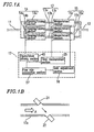
Figure 1A is a block diagram showing a structure of
a flow rate measurement apparatus according to embodiment 1
of the present invention.
Figure 1B is a diagram schematically showing a
structure of a measurement section of the flow rate
measurement apparatus shown in Figure 1A.
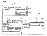
Figure 2 is a block diagram showing a structure of
the measurement section and a control section of the flow
rate measurement apparatus shown in Figure 1A.
Figure 3 is a block diagram showing a structure of
a control section of a flow rate measurement apparatus
according to embodiment 2 of the present invention.
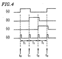
Figure 4 is a timing chart illustrating operations
of opening/closing sections 4a-4c and a first timer
section.
Figure 5 is a block diagram showing a structure of
a control section of a flow rate measurement apparatus
according to embodiment 3 of the present invention.
Figure 6 is a flow rate characteristic graph for
illustrating processing in the control section shown in
Figure 5.
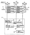
Figure 7 is a block diagram showing a structure of
a control section of a flow rate measurement apparatus
according to embodiment 4 of the present invention.
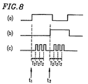
Figure 8 is a timing chart illustrating operations
of opening/closing sections 4a and 4b and a second timer
section.
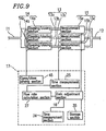
Figure 9 is a block diagram showing a structure of
a control section of a flow rate measurement apparatus
according to embodiment 5 of the present invention.
Figure 10 is a block diagram showing a structure of
a control section of a flow rate measurement apparatus
according to embodiment 6 of the present invention.
Figure 11A is a block diagram showing a structure
of a flow rate measurement apparatus according to
embodiment 7 of the present invention.
Figure 11B is a diagram schematically showing a
structure of a flow rate detecting section of the flow rate
measurement apparatus shown in Figure 11A.
Figure 12 is a block diagram showing a structure of
a measurement section of the flow rate measurement apparatus
shown in Figure 11A.
Figure 13 is a block diagram showing a structure of
a control section of a flow rate measurement apparatus
according to embodiment 8 of the present invention.
Figure 14 is a timing chart illustrating operations
of opening/closing sections 14a-14c and a third timer
section.
Figure 15 is a block diagram showing a structure of
a control section of a flow rate measurement apparatus
according to embodiment 9 of the present invention.
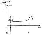
Figure 16 is a timing chart illustrating processing
in the control section shown in Figure 15.
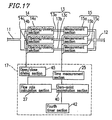
Figure 17 is a block diagram showing a structure of
a control section of a flow rate measurement apparatus
according to embodiment 10 of the present invention.
Figure 18 is a timing chart illustrating operations
of opening/ closing sections 14a and 14b and a fourth timer
section.
Figure 19 is a block diagram showing a structure of
a control section of a flow rate measurement apparatus
according to embodiment 11 of the present invention.
Figure 20 is a block diagram showing a structure of
a control section of a flow rate measurement apparatus
according to embodiment 12 of the present invention.
Figure 21 is a block diagram showing a structure of
a conventional flow rate measurement apparatus.
BEST MODE FOR CARRYING OUT THE INVENTION
Hereinafter, embodiments of the present invention
are described with reference to the drawings.
(Embodiment 1)
Figure 1A is a block diagram showing a structure of
a flow rate measurement apparatus according to embodiment 1
of the present invention. Figure 1B is a diagram
schematically showing a structure of a measurement section
of the flow rate measurement apparatus shown in Figure 1A.
Figure 2 is a block diagram showing a structure of the
measurement section and a control section of the flow rate
measurement apparatus shown in Figure 1A.
As shown in Figure 1A, the flow rate measurement
apparatus includes: a plurality of flow paths 13 provided
between an inflow path 11 and an outflow path 12;
opening/closing sections 14 for opening/closing the
plurality of flow paths 13; measurement sections 15 for
measuring the flow rate of fluid passing through at least
one of the plurality of flow paths 13; and a control
section 17 for controlling the opening/closing sections 14
and the measurement sections 15. The control section 17
includes: a gain adjustment section 16 for correcting a gain
of the measurement section 15 in the flow paths 13 closed
by the opening/closing sections 14; and open/close driving
section 45 for driving the opening/closing sections 14. In
the example illustrated in Figure 1A, the flow rate
measurement apparatus includes: the three flow paths 13
(13a-13c); the opening/closing sections 14 (14a-14c)
provided in the flow paths 13; and the measurement
sections 15 (15a-15c). The opening/closing section 14a
and the measurement section 15a are attached to the flow
path 13a. The opening/closing section 14b and the
measurement section 15b are attached to the flow path 13b.
The opening/closing section 14c and the measurement
section 15c are attached to the flow path 13c.
Fluid entering through the inflow path 11 passes
through the opened opening/closing sections 14 and the flow
rate thereof is measured by the measurement sections 15.
The opening/closing sections 14 and the measurement
sections 15 are controlled by the control section 17. The
opening/closing sections 14 can open or close their
respective flow paths 13. The measurement sections 15
measure the flow rate of fluid flowing through the flow paths
opened by the opening/closing sections 14. The total flow
rate from the inflow path 11 to the outflow path 12 is
obtained by the control section 17 by summing up flow rates,
which are measured for the respective flow paths by the
measurement sections 15.
By opening all of the flow paths 13, it is possible
to allow a fluid to flow therethrough at a high flow rate,
and it is also possible to measure the flow rate of the fluid.
By opening only one of the flow paths 13, it is possible
to allow a fluid to flow therethrough at a low flow rate.
Thus, the plurality of opening/closing sections 14, each
of which can be separately opened/closed by the open/close
driving section 45, are used, whereby selection of flow
paths according to the flow rate, or the like, are readily
achieved, and measurement is enabled over a wide flow rate
range.
The flow paths 13 may be formed by a plurality of
flow paths having the same cross-sectional area such that
the application range of the flow rate measurement apparatus
is increased, and maintenance thereof is facilitated.
Alternatively, the flow paths 13 may be formed by a plurality
of flow paths having different cross-sectional areas so that
an optimum path is selected according to the flow rate or
the like. In the example of the present invention, three
flow paths are provided, but this number is not especially
significant. Any number of flow paths can be provided so
long as it is two or more.
A flow rate calculation section 27 performs a
calculation of summing up flow rates which are measured for
the respective flow paths by the measurement sections 15.
In this case, Q = qa+qb+qc = Σq, where Q denotes the total
flow rate obtained by the flow rate calculation section 27,
and qa, qb, and qc denote the flow rates measured by the
measurement sections 15a, 15b, and 15c installed in the
flow paths 13a, 13b, and 13c in which the opening/closing
sections 14 are open.
When the opening/closing section 14a is close,
fluid does not flow through the flow path 13a. Therefore,
measurement of the flow rate of fluid by the measurement
section 15a does not produce an error in the overall
measurement of the flow rate. Since the sensitivity of a
sensor for measuring the flow rate is sometimes decreased
due to external disturbances, such as a temperature or the
like, a secular change, etc., it is necessary to correct
a measurement system in such a case. Such a correction is
achieved by adjusting the sensitivity of reception means
such that, for example, the maximum value of a signal
received from the sensor falls within a predetermined level
range. This gain adjustment is carried out, in a path 13
in which an opening/closing section 14 is closed, by a
corresponding measurement section 15.
In this correction, if the gain is far away from an
appropriate range, it is effective to notify a user about
the abnormal condition by using announcement means or the
like. Moreover, it is also effective to notify an external
administrative person about the abnormal condition by using
communication means or the like so that the abnormal
condition can be corrected earlier.
Figure 1B shows a portion of a structure of the
measurement section 15a provided in the flow path 13a shown
in Figure 1A. It should be noted that each of the
measurement sections 15b and 15c has the same structure as
that of the measurement section 15a.
An empty arrow A shown in Figure 1B indicates a
direction in which fluid flows in the flow path 13a. The
measurement section 15a includes a first transducer 21 and
a second transducer 22 provided in the flow path 13a. The
first transducer 21 and the second transducer 22 are placed
so as to face each other across the fluid flowing through
the flow path 13a. The first transducer 21 and the second
transducer 22 transmit and receive ultrasonic wave signals.
Figure 2 shows a structure of the measurement
section 15a provided in the flow path 13a shown in Figure 1A
in more detail. It should be noted that each of the
measurement sections 15b and 15c has the same structure as
that of the measurement section 15a.
As shown in Figure 2, the measurement section 15a
includes a transmission section 23 for transmitting a
periodic driving signal to the first transducer 21 and the
second transducer 22; an amplifying section 24 for
amplifying a received ultrasonic signal; a comparison
section 29 for comparing a signal output from the amplifying
section 24 and a reference signal; a repetition section 46
for receiving a signal output from the comparison section 29,
setting a number of repetitions when a detected signal is
equal to or greater than the reference signal, and repeating
transmission of ultrasonic waves between the first
transducer 21 and the second transducer 22 for the set
number of repetitions; and a delay section 10 for delaying
the transmission of ultrasonic waves during the repetition.
The gain adjustment section 16 corrects a gain of
the measurement section 15a by adjusting a gain of the
amplifying section 24.
When the comparison section 29 detects that a signal
equal to or greater than the reference signal is output from
the amplifying section 24, the comparison section 29
outputs to the repetition section 46 a signal indicating
the arrival of a received signal. The repetition section 46
receives a signal output from the comparison section 29 and
determines whether or not the number of times this signal
is received has reached the repetition number. When the
number of times this signal is received has reached the
predetermined repetition number, the repetition section 46
controls the transmission section 23 such that an
ultrasonic wave signal is transmitted from the transmission
section 23 through the delay section 10 for delaying the
signal by a predetermined time. In this way, the ultrasonic
wave signal is repeatedly transmitted from the transmission
section 23.
A switching section 26 switches between
transmission/reception of the first transducer 21 and the
second transducer 22. Specifically, ultrasonic wave
transmission where the first transducer 21 transmits an
ultrasonic wave signal and the second transducer 22
receives the ultrasonic wave signal is repeated for the set
number of repetitions. Thereafter, ultrasonic wave
transmission where the second transducer 22 transmits an
ultrasonic wave signal and the first transducer 21 receives
the ultrasonic wave signal is repeated for the set number
of repetitions.
A time measurement section 25 calculates a time
spent for repeating the ultrasonic wave transmission from
the first transducer 21 to the second transducer 22 for the
set number of repetitions (first transmission time) and a
time for repeating the ultrasonic wave transmission from
the second transducer 22 to the first transducer 21 for the
set number of repetitions (second transmission time).
For example, the time measurement section 25 is a
timer counter.
The flow rate calculation section 27 calculates the
velocity of fluid based on the time difference between the
first transmission time and the second transmission time
and calculates the flow rate of the fluid based on the
cross-sectional area of the flow path 13 and the velocity
of the fluid.
Thus, ultrasonic waves are utilized in the
measurement section so as to measure the flow rate without
causing a disturbance in the flow of the fluid. Moreover,
due to the available combinations of a plurality of flow
paths, the flow rate can be quickly measured with high
accuracy over a wide flow rate range.
However, the sensitivities of the first
transducer 21 and the second transducer 22 are sometimes
decreased due to external disturbances, such as a
temperature or the like, a secular change, etc. Thus, it
is probable that, in the amplifying section 24 for
amplifying a received signal, the gain of the received signal
is not sufficient so that the flow rate cannot be measured
accurately. In order to prevent such a phenomenon, in a path
through which fluid is not flowing, the gain adjustment
section 16 corrects the gain of the amplifying section 24
and adjusts a signal so as to have an amplitude determinable
by the comparison section 29. When this operation is
performed, immediately after the opening/closing
section 14a is opened, the measurement section 15a can
quickly start a measurement operation. Even if there is a
transducer whose sensitivity cannot be restored, the
measurement can be continued by excluding the flow path which
includes this transducer and opening another flow path.
In this embodiment, the sensitivity of the receiver
is adjusted. However, the same effect can be obtained by
adjusting the power of the transmitter.
In the above example, ultrasonic elements are used
in the measurement section, but the present invention is
not limited thereto. Similar measurements of flow rate can
be achieved by using, as the measurement section, a heat
radiation section which utilizes a power source provided
in a flow path as a drive source; at least one thermosensitive
section for detecting a change in temperature caused by the
flow rate; and a flow rate calculation section for
calculating the flow rate based on a change in a signal in
the thermosensitive section.
However, the sensitivities of the heat radiation
section and the thermosensitive section may also be
decreased due to external disturbances, such as a
temperature or the like, a secular change, etc. Thus, it
is probable that, in the amplifying section 24 for
amplifying a received signal, the gain of the received signal
is not sufficient so that the flow rate cannot be measured
accurately. In order to prevent such a phenomenon, in a path
through which fluid is not flowing, the gain adjustment
section 16 corrects the gain of the amplifying section 24
and adjusts a signal so as to have an amplitude determinable
by the comparison section 29.
When this operation is performed, immediately after
the opening/closing section 14a is opened, the measurement
section 15a can quickly start a measurement operation.
Even if there is a heat radiation section or a
thermosensitive section whose sensitivity cannot be
restored, the measurement can be continued by excluding the
flow path which includes this transducer and opening another
flow path. Furthermore, the same effects can be obtained
by adjusting the power supplied to the heat radiation
section.
(Embodiment 2)
Hereinafter, a flow rate measurement apparatus
according to embodiment 2 of the present invention is
described. The block diagrams of Figures 1A and 1B which
have been used in embodiment 1 are used again to describe
a structure of this embodiment. Figure 3 is a block diagram
showing a structure of the control section 17. Figure 4 is
a timing chart illustrating operations of the control
section 17. Embodiment 2 is different from embodiment 1 in
that the control section 17 includes a first timer
section 31 for performing time management such that the
opening/closing sections 14 are switched at a predetermined
time interval.
In Figure 4, part (a) shows an operation of the
opening/closing section 14a, part (b) shows an operation
of the opening/closing section 14b, part (c) shows an
operation of the opening/closing section 14c, and part (d)
shows an operation of the first timer section 31.
The first timer section 31 starts its operation
simultaneously with the opening of the opening/closing
section 14a. The first timer section 31 transmits a pulse
signal to the control section 17 every predetermined time
period (herein, T1). The control section 17 switches an
opening/closing section so as to be opened based on the pulse
signal from the first timer section 31. During the first
period T1 (from time t0 to time t1), the control section 17
opens the opening/closing section 14a, whereby fluid flows
through the flow path 13a. During the next period T1 (from
time t1 to time t2), the control section 17 opens the
opening/closing section 14b and thereafter closes the
opening/closing section 14a, whereby fluid flows through
the flow path 13b. It should be noted that correction of
the gain of the amplifying section in the measurement
section 15b is completed before the opening/closing
section 14b is opened. During next period T1 (from time t2
to time t3), the control section 17 opens the
opening/closing section 14c and thereafter closes the
opening/closing section 14b, whereby fluid flows through
the flow path 13c. It should be noted that correction of
the gain of the amplifying section in the measurement
section 15c is completed before the opening/closing
section 14c is opened.
In this way, a flow path in which the flow rate has
already been measured is switched with the passing of every
predetermined period.
With this arrangement, even when the flow of fluid
is maintained and the flow rate thereof is being measured,
the gain of the amplifying section of the measurement
section 15 in a flow path 13 in which an opening/closing
section 14 is closed is corrected. Even when the gain in
a flow path in which the flow rate is being measured is varied,
especially, due to a secular change of a transducer, the
flow path 13 is switched by the opening/closing sections 14,
whereby measurement with high stability and without
decreased reception sensitivity is achieved within a
certain time interval, and a decrease in accuracy can be
prevented.
(Embodiment 3)
Hereinafter, a flow rate measurement apparatus
according to embodiment 3 of the present invention is
described. The block diagrams of Figures 1A and 1B which
have been used in embodiment 1 are used again to describe
a structure of this embodiment. Figure 5 is a block diagram
showing a structure of the control section 17. Figure 6 is
a timing chart illustrating operations of the control
section 17 based on a flow rate characteristic.
Embodiment 3 is different from embodiments 1 and 2 in that
the control section 17 includes a flow rate determination
section 32. When the measured flow rate of the fluid is
lower than a predetermined flow rate, the flow rate
determination section 32 transmits to the gain adjustment
section 16 a signal which directs the start of correction
of the gain of the measurement section 15. When the
measured flow rate of the fluid is higher than a
predetermined flow rate, the flow rate determination
section 32 transmits to the gain adjustment section 16 a
signal which directs the stop of correction of the gain of
the measurement section 15.
The control section 17 opens the opening/closing
section 14a at time t1, shown in Figure 6. As a result,
fluid flows through the flow path 13a. The flow rate
calculation section 27 calculates the flow rate of the fluid
flowing through the flow path 13a based on an output of the
measurement section 15a. When the flow rate calculated by
the flow rate calculation section becomes lower than a
predetermined value (Q1 at time t2 shown in Figure 6), the
flow rate determination section 32 transmits a signal to
the control section 17 such that the gains of the amplifying
sections of the measurement sections 15b and 15c in the
paths in which the opening/ closing sections 14b and 14c are
closed are corrected. This is because the probability that
the opening/closing sections 14 is opened so as to allow
the fluid to flow through the path 13b for measuring the
flow rate by using a plurality of flow paths decreases along
with the decrease of the flow rate. Furthermore, since the
flow rate is low, and accordingly, the flow of the fluid
is small, correction of the gain can be performed in a flow
path 13 in which an opening/closing sections 14 is closed,
without errors which may result from an external disturbance
from downstream. In this embodiment, the correction of the
gain is performed immediately after the flow rate becomes
lower than value Q1. However, considering that noise may
be superposed on a flow rate signal, or that the flow rate
itself may vary, correction of the gain may be started after
a lapse of a certain time since the flow rate has become
equal to or lower than value Q1, whereby correction can be
more stable.
When the flow rate calculated by the flow rate
calculation section 27 becomes higher than a predetermined
value (Q2 at time t3 shown in- Figure 6), the flow rate
determination section 32 transmits a signal to the control
section 17 such that an operation for correcting the gains
of the amplifying sections of the measurement sections 15b
and 15c in the paths in which the opening/ closing
sections 14b and 14c are closed is stopped. This is because
the correction of the gain of the measurement section 15
can be affected by an external disturbance from downstream
which may be caused due to the high flow rate. Furthermore,
in preparation for a case where it is required to open the
opening/closing sections for allowing the fluid to flow
through the flow paths in order to measure a high flow rate,
correction of the gain is stopped such that measurement of
the flow rate can be immediately started.
(Embodiment 4)
Hereinafter, a flow rate measurement apparatus
according to embodiment 4 of the present invention is
described. The block diagrams of Figures 1A and 1B which
have been used in embodiment 1 are used again to describe
a structure of this embodiment. Figure 7 is a block diagram
showing a structure of the control section 17. Figure 8 is
a timing chart illustrating operations of the control
section 17. Embodiment 4 is different from embodiments 1,
2, and 3 in that the control section 17 includes a second
timer section 33 for performing time management such that
correction of the gain of the measurement section 15 in a
closed flow path is performed at a predetermined time
interval.
In Figure 8, part (a) shows an operation of the
opening/closing section 14a, part (b) shows an operation
of the opening/closing section 14b, and part (c) shows an
operation of the second timer section 33.
The second timer section 33 starts its operation at
time t1 show in Figure 8. The second timer section 33
transmits a pulse signal to the control section 17 every
time a predetermined time, shorter than a period when the
opening/closing sections 14a-14c are open (herein, T2),
passes. In response to the pulse signal from the second
timer section 33, the gain adjustment section 16 in the
control section 17 corrects the gain of a measurement
section provided in a closed flow path.
In the example illustrated in Figure 8, during a
period from time t1 to time t2, the opening/closing
section 14a is open whereas the opening/ closing
sections 14b and 14c are close. In response to the pulse
signal from the second timer section 33, the gain adjustment
section 16 in the control section 17 corrects the gain of
the measurement section 15b provided in the closed flow
path 13b. Similarly, the gain adjustment section 16 in the
control section 17 may correct the gain of the measurement
section 15c provided in the closed flow path 13c, in
response to the pulse signal from the second timer
section 33.
At time t2, the opening/closing section 14a is
closed, and the opening/closing section 14b is opened. The
second timer section 33 starts its operation at time t2 so
as to transmit a pulse signal to the control section 17 after
every predetermined period (herein, T2) passes. In response
to the pulse signal from the second timer section 33, the
gain adjustment section 16 in the control section 17
corrects the gain of the measurement section 15a provided
in the closed flow path 13a.
Thus, according to this embodiment, the gain of a
measurement section 15 in a path 13 in which an
opening/closing section 14 is close can be corrected at an
interval of a predetermined time interval T2. Therefore,
even when an error is caused in the gain due to secular
changes including external disturbance, such as temperature,
humidity, etc., such an error can be corrected within a
predetermined time so as to reduce variations in measurement.
Thus, the flow rate measurement apparatus of the present
invention has a sufficient capacity to deal with a case where
an abrupt increase in the flow rate occurs, and accordingly,
it is required to open the closed flow paths.
(Embodiment 5)
Hereinafter, a flow rate measurement apparatus
according to embodiment 5 of the present invention is
described. The block diagrams of Figures 1A and 1B which
have been used in embodiment 1 are used again to describe
a structure of this embodiment. Figure 9 is a block diagram
showing a structure of the control section 17.
Embodiment 5 is different from embodiments 1-4 in that the
control section 17 includes a time measurement section 34
and a storage section 35.
The control section 17 opens a plurality of the
opening/closing sections 14 so as to allow fluid to flow
therethrough. In the meantime, the control section 17
corrects the gain of a measurement section 15 in a flow path
in which an opening/closing section 14 is closed. The
control section 17 has a time measurement section 34. The
time measurement section 34 transmits a signal to the gain
adjustment section 16 at a prescribed time such that the
gain of the measurement section 15 in the closed flow path 13
is corrected. In such a structure, the state of the flow
rate which is specific to a system in which the flow rate
measurement apparatus is installed has been previously
measured, and the gain is corrected, for example, at any
time when the flow rate is low, whereby the accuracy of the
measurement section 15 can be adjusted at an optimum time.
Furthermore, the preset time may be statistically
determined. For example, in the case of gas flow rate
measurement equipment for household use, the preset time
is any time within a day except for breakfast time, lunchtime,
and a period from evening to night including a bath/shower
time, i.e., any time during which gas (measured fluid) rarely
flows. By previously setting the number of adjustment
operations and times at which the adjustment is performed,
the adjustment can be achieved with only a small correction
error which may be caused in the gain.
The control section 17 includes the time
measurement section 34 and the storage section 35. A time
during which a stable flow rate Q, equal to or lower than
a predetermined flow rate, is continuously maintained, is
measured by the time measurement section 34 and stored in
the storage section 35. An operation for correcting the
gain of a measurement section 15 in a closed flow path is
performed at the time stored in the storage section 35. The
use conditions inherent to a system to which the flow rate
measurement apparatus is attached and the state of the system
are previously stored, and the state of the gain of the
measurement section 15 is checked at a time when the flow
rate is stable, whereby the measurement section 15 can be
adjusted more accurately.
For example, assume a case where the present
invention is applied to a gas flow rate meter for household
use. The time for meals in the morning and around noon, a
period from evening to night when a bath is used, a period
when heating apparatuses are used, etc., are different among
families according to their ways of life. Thus, the times
when the flow rate measured by the measurement section 15
is equal to or lower than a predetermined value are examined,
and by repeating this examination, such times are stored
and learned. The control section 17 determines a time to
correct the gain of the measurement section 15 by using the
time measurement section 34. Furthermore, when a calendar
function is provided, it is indicated that the total time
during which gas is used is sometimes considerably different
between a weekday and a day of the weekend. Such information
can be incorporated in the storage section as a factor of
determination.
(Embodiment 6)
Hereinafter, a flow rate measurement apparatus
according to embodiment 6 of the present invention is
described. The block diagrams of Figures 1A and 1B which
have been used in embodiment 1 are used again to describe
a structure of this embodiment. Figure 10 is a block
diagram showing a structure of the control section 17.
Embodiment 6 is different from embodiments 1-5 in that the
control section 17 includes a communication section 36.
In this embodiment, the control section 17 includes
a communication section 36. Usually, the control
section 17 opens a plurality of opening/closing sections 14
so as to allow the flow of fluid. In the meantime, the
control section 17 corrects the gain of measurement
sections 15 in paths in which opening/closing sections 14
are closed. The time to correct this gain may be
automatically controlled by using, for example, the second
timer section 33 (Figure 7) incorporated in the control
section 17 or the like. However, in some cases, a user or
an external institution requests a confirmation operation
at any time. In preparation for such a case, the
communication section 36 of Figure 10 is provided such that
the flow rate measurement apparatus can communicate with
an external party. The user directs the start of the
confirmation operation by using setting means, such as a
switch or a remote controller, and in response to this
direction signal, the control section 17 corrects the gain
of the measurement sections 15 in paths in which the
opening/closing sections 14 are closed. With such a
structure, a user can correct the gain of a measurement
section externally at any time. Thus, even when a system
becomes unstable due to a sudden external disturbance or
the like, a user can manually transmits a signal for
correcting the gain.
Furthermore, as an external signal source for
generating a signal that requests correction of the gain,
equipment installed in a downstream portion of the flow path
can be used. For example, if it is a gas apparatus, a gas
water heater 37 or the like can be used. A gas measurement
section, or the like, included in the gas apparatus estimates
the gas flow rate. When the gas measurement section
determines that the gas flow rate is equal to or lower than
a predetermined value, the gas measurement section sends
a request for gain correction through the communication
section 36 to the control section 17 of the flow rate
measurement apparatus. With such an arrangement, the gain
correction can be reliably performed by externally
supplying a signal when the flow rate of fluid is low.
Similarly, as an external signal source, equipment
installed in an upstream portion of the inflow path 11, for
example, a flow rate measurement section 38 in an output
section of a large supply plant, may be used. When the flow
rate measurement section determines that the amount of
flowing fluid is equal to or lower than a predetermined
amount, the flow rate measurement section sends a request
for gain correction through the communication section 36
to the control section 17 of the flow rate measurement
apparatus. With this arrangement, the gain correction can
be reliably performed by externally supplying a signal when
the flow rate of fluid is low. The externally-supplied
signal may be supplied from an apparatus including a timer
section or from a central meter to which apparatuses are
connected. With this structure, correction of the gain can
be externally requested within a certain time.
It is apparent that some of embodiments 1-6
described hereinabove can be combined. When unnecessary
gain correction is omitted by performing gain correction
only when the value of the flow rate calculation section
indicates an abnormal value, power consumption is reduced.
In another embodiment, when the flow rate is equal to or
smaller than a predetermined flow rate value, this is
considered as a change in the gain, and accordingly, gain
correction is performed so as to deal with a very small
leakage of fluid. Such an embodiment can be readily
practiced by those skilled in the art. Furthermore, a
plurality of flow paths are used so as to measure the flow
rate of fluid over a wide range of a very low flow rate to
a large flow rate, and to correct the gain of a measurement
section in a closed flow path. In this manner, the flow rate
measurement can always be performed with high accuracy.
Furthermore, a periodical operation of an opening/closing
section can prevent itself from being stuck to the flow path,
and the reliability of the measurement apparatus can be
improved.
(Embodiment 7)
Figure 11A is a block diagram showing a structure
of a flow rate measurement apparatus according to
embodiment 7 of the present invention. Figure 11B is a
diagram schematically showing a structure of a measurement
section shown in Figure 11A. Figure 12 is a block'diagram
showing a structure of the measurement section shown in
Figure 11A.
In Figures 11A and 11B, like elements are indicated
by like reference numerals used in Figures 1A and 1B, and
detailed descriptions thereof are omitted. A control
section 17 shown in Figure 11A includes a zero-point
examination section 40.
The control section 17 controls the
opening/closing of opening/closing sections 14a-14c while
performing a flow rate calculation similar to that described
with reference to Figures 1A and 1B. When the
opening/closing section 14a is close, fluid does not flow
through a flow path 13a. In this case, the flow rate
measured by a measurement section 15a must be 0. The
zero-point of the measurement section 15a is sometimes off
of a correct point due to external disturbance, such as
temperature, and variation in temperature, secular change,
etc., in a flow rate calculation section 27. In such a case,
the flow rate measured by the measurement section 15a is
not necessarily 0. The zero-point examination section 40
in the control section 17 detects, based on a value of the
flow rate calculation section 27, the zero-point of the
measurement section 15a provided in the flow path 13a in
which the opening/closing section 14a is close so as to
perform a zero-point correction. This zero-point
correction is achieved, for example, by using a value
measured by the measurement section 15a when the
opening/closing section 14a is closed as a reference value
(value which should be obtained when the flow rate is zero,
i.e., zero-point) and increasing or decreasing a value
measured by the measurement section 15a when the
opening/closing section 14a is next opened by the reference
value. This zero-point correction can be performed in a
measurement section 15 provided in each of flow paths 13
in which opening/closing sections 14 are close.
In this correction, if the zero-point is far off of
a correct point, it is effective-to notify a user about the
abnormal condition by using announcement means or the like.
Moreover, it is also effective to notify an external
administrative person about the abnormal condition by using
communication means or the like so that the abnormal
condition can be corrected in an earlier phase.
The flow paths 13 may be formed by a plurality of
flow paths having the same cross-sectional area such that
the application range of the flow rate measurement apparatus
is increased, and maintenance thereof is facilitated.
Alternatively, the flow paths 13 may be formed by a plurality
of flow paths having different cross-sectional areas so that
an optimum path is selected according to the flow rate or
the like. In the example of the present invention, three
flow paths are provided, but this number is not especially
significant. Any number of flow paths can be provided so
long as it is two or more.
Figure 11B shows a portion of a structure of the
measurement section 15a provided in the flow path 13a shown
in Figure 11A. It should be noted that each of the
measurement sections 15b and 15c has the same structure as
that of the measurement section 15a.
An empty arrow A shown in Figure 11B indicates a
direction in which fluid flows in the flow path 13a. The
measurement section 15a includes a first transducer 21 and
a second transducer 22 provided in the flow path 13a. The
first transducer 21 and the second transducer 22 are placed
so as to face each other across the fluid flowing through
the flow path 13a. The first transducer 21 and the second
transducer 22 transmit and receive ultrasonic wave signals.
Figure 12 shows a structure of the measurement
section 15a provided in the flow path 13a shown in
Figure 11A in more detail. It should be noted that each of
the measurement sections 15b and 15c has the same structure
as that of the measurement section 15a.
As shown in Figure 12, the measurement section 15a
includes a transmission section 23 for transmitting a
periodic driving signal to the first transducer 21 and the
second transducer 22; an amplifying section 24 for
amplifying a received ultrasonic signal; a comparison
section 29 for comparing a signal output from the amplifying
section 24 and a reference signal; a repetition section 46
for receiving a signal output from the comparison section 29,
setting a number of repetitions when a detected signal is
equal to or greater than the reference signal, and repeating
transmission of ultrasonic waves between the first
transducer 21 and the second transducer 22 for the set
number of repetitions; and a delay section 10 for delaying
the transmission of ultrasonic waves during the repetition.
The zero-point examination section 40 includes a
storage section (not shown) and an increase/decrease
section (not shown). A value measured by the measurement
section 15a when the opening/closing section 14a is close
is stored in the storage section as a reference value (value
which should be obtained when the flow rate is zero, i.e.,
zero-value). The increase/decrease section increases or
decreases a value which is measured by the measurement
section 15a when the opening/closing section 14a is next
opened and fluid actually flows through the path 13a, by
the reference value.
For example, in the case where the value measured
by the measurement section 15a when the opening/closing
section 14a is closed (zero-value) is 5 liters, and the
value which is measured by the measurement section 15a when
the opening/closing section 14a is next opened and the fluid
actually flows through the path 13a is 15 liters, the
increase/decrease section performs a subtraction: 15-5=10.
In the case where the value measured by the measurement
section 15a when the opening/closing section 14a is closed
(zero-value) is -5 liters, and the value measured by the
measurement section 15a when the opening/closing
section 14a is next opened and the fluid actually flows
through the path 13a is 15 liters, the increase/decrease
section performs an addition: 15-(-5)=15+5=20.
In this way, the zero-point examination section 40
detects the zero-value of the measurement section 15, and
a value measured by the measurement section 15 is corrected
based on the detected zero-value, whereby the zero-value
correction is achieved.
When the comparison section 29 detects that a signal
equal to or greater than the reference signal is output from
the amplifying section 24, the comparison section 29
outputs to the repetition section 46 a signal indicating
the arrival of a received signal. The repetition section 46
receives a signal output from the comparison section 29 and
determines whether or not the number of times this signal
is received has reached the repetition number. When the
number of times this signal is received has reached the
predetermined repetition number, the repetition section 46
controls the transmission section 23 such that an
ultrasonic wave signal is transmitted from the transmission
section 23 through the delay section 10 for delaying the
signal by a predetermined time. In this way, the ultrasonic
wave signal is repeatedly transmitted from the transmission
section 23.
A switching section 26 switches between
transmission/reception of the first transducer 21 and the
second transducer 22. Specifically, ultrasonic wave
transmission where the first transducer 21 transmits an
ultrasonic wave signal and the second transducer 22
receives the ultrasonic wave signal is repeated for the set
number of repetitions. Thereafter, ultrasonic wave
transmission where the second-transducer 22 transmits an
ultrasonic wave signal and the first transducer 21 receives
the ultrasonic wave signal is repeated for the set number
of repetitions.
A time measurement section 25 calculates a time
spent for repeating the ultrasonic wave transmission from
the first transducer 21 to the second transducer 22 for the
set number of repetitions (first transmission time) and a
time for repeating the ultrasonic wave transmission from
the second transducer 22 to the first transducer 21 for the
set number of repetitions (second transmission time).
For example, the time measurement section 25 is a
timer counter.
The flow rate calculation section 27 calculates the
velocity of fluid based on the time difference between the
first transmission time and the second transmission time
and calculates the flow rate of the fluid based on the
cross-sectional area of the flow path 13 and the velocity
of the fluid.
Thus, ultrasonic waves are utilized in the
measurement section so as to measure the flow rate without
causing a disturbance in the flow of the fluid. Moreover,
due to the available combinations of a plurality of flow
paths, the flow rate can be quickly measured with high
accuracy over a wide flow rate range.
However, offset is sometimes caused in the first
transducer 21, the second transducer 22, and the control
section 17 due to external disturbances, such as a
temperature or the like, a secular change, etc. Thus, it
is probable that the control section 17 erroneously
determines, in response to a received signal, that fluid
is flowing through a flow path when none is flowing
therethrough.
In order to prevent such a phenomenon, the zero-point
examination section 40 corrects the zero-point of the
measurement section 15 in a path through which fluid is not
flowing.
When this operation is performed, immediately after
the opening/closing section 14a is opened, the measurement
section 15a can quickly start a measurement operation.
Even if there is a transducer, a measurement section, a
control section, or the like, whose offset cannot be amended,
the measurement can be continued by excluding the flow path
which includes such a defective element and opening another
flow path.
In the above example, ultrasonic elements are used
in the measurement section, but the present invention is
not limited thereto. Similar measurement of flow rate can
be achieved by using, as the measurement section, a heat
radiation section which utilizes a power source provided
in a flow path as a drive source; at least one thermosensitive
section for detecting a change in temperature caused
according to the flow rate; and a flow rate calculation
section for calculating the flow rate based on a change in
a signal in the thermosensitive section.
However, the sensitivities of the heat radiation
section and the thermosensitive section may also be
decreased due to external disturbances, such as a
temperature or the like, a secular change, etc. Thus, it
is probable that in the amplifying section 24 for amplifying
a received signal, the gain of the received signal is not
sufficient so that the flow rate cannot be measured. In
order to prevent such a phenomenon, in a path through which
fluid is not flowing, the gain adjustment section 16
corrects the gain of the amplifying section 24 and adjusts
a signal so as to have an amplitude determinable by the
comparison section 29. When this operation is performed,
immediately after the opening/closing section 14a is opened,
the measurement section 15a can quickly start a measurement
operation. Even if there is a heat radiation section or a
thermosensitive section whose sensitivity cannot be
restored, the measurement can be continued by excluding the
flow path which includes such a defective element and opening
another flow path. Furthermore, the same effects can be
obtained by adjusting the power supplied to the heat
radiation section.
(Embodiment 8)
Hereinafter, a flow rate measurement apparatus
according to embodiment 8 of the present invention is
described. The block diagrams of Figures 11A and 11B which
have been used in embodiment 7 are used again to describe
a structure of this embodiment. In this embodiment, like
elements are indicated by like reference numerals used in
embodiment 7, and detailed descriptions thereof are omitted.
Figure 13 is a block diagram showing a structure of the
control section 17. Figure 14 is a timing chart
illustrating operations of the control section 17.
Embodiment 8 is different from embodiment 7 in that
the control section 17 includes a third timer section 41
for performing time management such that the
opening/closing sections 14 are switched at a predetermined
time interval.
In Figure 14, part (a) shows an operation of the
opening/closing section 14a, part (b) shows an operation
of the opening/closing section 14b, part (c) shows an
operation of the opening/closing section 14c, and part (d)
shows an operation of the third timer section 41.
The third timer section 41 starts its operation
simultaneously with the opening of the opening/closing
section 14a. The third timer section 41 transmits'a pulse
signal to the control section 17 every predetermined time
period (herein, T1). The control section 17 switches an
opening/closing section so as to be opened based on the pulse
signal from the third timer section 41. During the first
period T1 (from time t0 to time t1), the control section 17
opens the opening/closing section 14a, whereby fluid flows
through the flow path 13a. During the next period T1 (from
time t1 to time t2), the control section 17 opens the
opening/closing section 14b and thereafter closes the
opening/closing section 14a, whereby fluid flows through
the flow path 13b. It should be noted that zero-point
correction for the measurement section 15b is completed
before the opening/closing section 14b is opened. During
the next period T1 (from time t2 to time t3), the control
section 17 opens the opening/closing section 14c and
thereafter closes the opening/closing section 14b, whereby
fluid flows through the flow path 13c. It should be noted
that zero-point correction for the measurement section 15c
is completed before the opening/closing section 14c is
opened.
In this way, a flow path in which the flow rate is
measured is switched with the passing of every predetermined
period.
With this arrangement, even during when the flow of
fluid is kept and the flow rate thereof is being measured,
the zero-point correction is performed for a measurement
section 15 in a flow path 13 in which an opening/closing
section 14 is closed. Even when the zero-point in a flow
path in which measurement is being performed is shifted from
a correct point due to a secular change, the flow path 13
is switched by the opening/closing sections 14, whereby
measurement with high stability and without a shifted
zero-point is achieved within a certain time interval, and
a decrease in accuracy can be prevented.
(Embodiment 9)
Hereinafter, a flow rate measurement apparatus
according to embodiment 9 of the present invention is
described. The block diagrams of Figures 11A and 11B which
have been used in embodiment 7 are used again to describe
a structure of this embodiment. In this embodiment, like
elements are indicated by like reference numerals used in
embodiment 7, and detailed descriptions thereof are omitted.
Figure 15 is a block diagram showing a structure of the
control section 17. Figure 16 is a timing chart
illustrating operations of the control section 17.
Embodiment 9 is different from embodiments 7 and 8 in that
the control section 17 includes a flow rate determination
section 32. When the measured flow rate of the fluid is
lower than a predetermined flow rate, the flow rate
determination section 32 transmits to the zero-point
examination section 40 a signal which directs the start of
zero-value correction of the measurement section 15. When
the measured flow rate of the fluid is higher than a
predetermined flow rate, the flow rate determination
section 32 transmits to the zero-point examination
section 40 a signal which directs the stop of zero-value
correction of the measurement section 15.
The control section 17 opens the opening/closing
section 14a at time t1 shown in Figure 16. As a result,
fluid flows through the flow path 13a. The flow rate
calculation section 27 calculates the flow rate of the fluid
flowing through the flow path 13a based on an output of the
measurement section 15a. When the flow rate calculated by
the flow rate calculation section 27 becomes lower than a
predetermined value (Q1 at time t2 shown in Figure 16), the
flow rate determination section 32 transmits a signal to
the control section 17 such that the zero-points of the
measurement sections 15b and 15c in the paths in which the
opening/ closing sections 14b and 14c are closed are
corrected. This is because the probability that the
opening/closing sections 14 are opened so as to allow the
fluid to flow through the path 13b for measuring the flow
rate by using a plurality of flow paths decreases along with
the decrease of the flow rate. Furthermore, since the flow
rate is low, and accordingly, the flow of the fluid is small,
examination of the zero-point can be performed in a flow
path 13 in which an opening/closing sections 14 is closed,
without causing an error which may result from an external
disturbance from downstream. In this embodiment,
examination of the zero-point is performed immediately
after the flow rate becomes lower than value Q1. However,
considering that noise may be superposed on a flow rate
signal, or that the flow rate itself may vary, the
examination of the zero-point may be started after a lapse
of a certain time since the flow rate has become equal to
or lower than value Q1, whereby correction can be more
stable.
When the flow rate calculated by the flow rate
calculation section 27 becomes higher than a predetermined
value (Q2 at time t3 shown in Figure 16), the flow rate
determination section 32 transmits a signal to the control
section 17 such that an operation for correcting the
zero-points of the measurement sections 15b and 15c in the
paths in which the opening/ closing sections 14b and 14c are
closed is stopped. This is because the zero-point
correction of the measurement section 15 can be affected
by an external disturbance from downstream which may be
caused due to the high flow rate. Furthermore, in
preparation for a case where it is required to open the
opening/closing sections for allowing the fluid to flow
through the flow paths in order to measure a high flow rate,
the zero-point examination is stopped such that measurement
of the flow rate can be immediately started.
(Embodiment 10)
Hereinafter, a flow rate measurement apparatus
according to embodiment 10 of the present invention is
described. The block diagrams of Figures 11A and 11B which
have been used in embodiment 7 are used again to describe
a structure of this embodiment. In this embodiment, like
elements are indicated by like reference numerals used in
embodiment 7, and detailed descriptions thereof are omitted.
Figure 17 is a block diagram showing a structure of the
control section 17. Figure 18 is a timing chart
illustrating operations of the control section 17.
Embodiment 10 is different from embodiment 7, embodiment 8,
and embodiment 9 in that the control section 17 includes
a fourth timer section 42 for performing time management
such that the zero-point of a measurement section in a closed
flow path is corrected at a predetermined time interval.
In Figure 18, part (a) shows an operation of the
opening/closing section 14a, part (b) shows an operation
of the opening/closing section 14b, and part (c) shows an
operation of the fourth timer section 42.
The fourth timer section 42 starts its operation at
time t1 show in Figure 18. The fourth timer section 42
transmits a pulse signal to the control section 17 every
time a predetermined time shorter than a period when the
opening/closing sections 14a-14c are open (herein, T2)
passes. In response to the pulse signal from the fourth
timer section 42, the zero-point examination section 40 in
the control section 17 examines the zero-point of a
measurement section provided in a closed flow path.
In the example illustrated in Figure 18, during a
period from time t1 to time t2, the opening/closing
section 14a is open whereas the opening/ closing
sections 14b and 14c are close. In response to the pulse
signal from the fourth timer section 42, the zero-point
examination section 40 in the control section 17 examines
the zero-point of the measurement section 15b provided in
the closed flow path 13b. Similarly, the zero-point
examination section 40 in the control section 17 may
examine the zero-point of the measurement section 15c
provided in the closed flow path 13c, in response to the
pulse signal from the fourth timer section 42.
At time t2, the opening/closing section 14a is
closed, and the opening/closing section 14b is opened. The
fourth timer section 42 starts its operation at time t2 so
as to transmit a pulse signal to the control section 17 every
time a predetermined period (herein, T2) passes. In
response to the pulse signal from the fourth timer section 42,
the zero-point examination section 40 in the control
section 17 examines the zero-point of the measurement
section 15a provided in the closed flow path 13a.
Thus, according to this embodiment, the zero-point
of a measurement section 15 in a path 13 in which an
opening/closing section 14 is close can be corrected at an
interval of a predetermined time interval T2. Therefore,
even when the zero-point is shifted due to secular changes
including external disturbance, such as temperature,
humidity, etc., such a shift can be amended within a
predetermined time so as to reduce variations in measurement.
Thus, the flow rate measurement apparatus of the present
invention has a sufficient capacity to deal with a case where
an abrupt increase in the flow rate occurs, and accordingly,
it is required to open the closed flow paths.
(Embodiment 11)
Hereinafter, a flow rate measurement apparatus
according to embodiment 11 of the present invention is
described. The block diagrams of Figures 11A and 11B which
have been used in embodiment 7 are used again to describe
a structure of this embodiment. In this embodiment, like
elements are indicated by like reference numerals used in
embodiment 7, and detailed descriptions thereof are omitted.
Figure 9 is a block diagram showing a structure of the
control section 17. Embodiment 11 is different from
embodiments 7-10 in that the control section 17 includes
a time measurement section 34 and a storage section 35.
The control section 17 opens a plurality of the
opening/closing sections 14 so as to allow fluid to flow
therethrough. In the meantime, the control section 17
corrects the zero-point of a measurement section 15 in a
flow path in which an opening/closing section 14 is closed.
The control section 17 has a time measurement
section 34. The time measurement section 34 transmits a
signal to the zero-point examination section 40 at a
prescribed time such that the zero-point of the measurement
section 15 in the closed flow path 13 is corrected. In such
a structure, the state of a flow rate which is specific to
a system in which the flow rate measurement apparatus is
installed has been previously measured, and the zero-point
is corrected, for example, at any time within a day when
the flow rate is low, whereby the accuracy of the measurement
section 15 can be adjusted at an optimum time. Furthermore,
the preset time may be statistically determined. For
example, in the case of gas flow rate measurement equipment
for household use, the preset time is any time within a day
except for breakfast time, lunchtime, and a period from
evening to night including a bath/shower time, i.e., any
time during which gas (measured fluid) rarely flows. By
previously setting the number of adjustment operations and
times at which the adjustment is performed, the adjustment
can be achieved with a small examination error which may
be caused in the zero-point.
The control section 17 includes the time
measurement section 34 and the storage section 35. A time
during which a stable flow rate Q, equal to or lower than
a predetermined flow rate, is continuously maintained is
measured by the time measurement section 34 and stored in
the storage section 35. An operation for correcting the
zero-point of a measurement section 15 in a closed flow path
is performed at the time stored in the storage section 35.
The use conditions inherent to a system to which the flow
rate measurement apparatus is attached and the state of the
system are previously stored, and the state of the zero-point
of the measurement section 15 is checked at a time when the
flow rate is stable, whereby the measurement section 15 can
be adjusted more accurately.
For example, assume a case where the present
invention is applied to a gas flow rate meter for household
use. The times for meals in the morning and around noon,
a period from evening to night when a bath is used, a period
when heating apparatuses are used, etc., are different among
families according to their ways of life. Thus, the times
when the flow rate measured by the measurement section 15
is equal to or lower than a predetermined value are examined,
and by repeating this examination, such times are stored
and learned. The control section 17 determines a time to
correct the zero-point of the measurement section 15 by
using the time measurement section 34. Furthermore, when
a calendar function is provided, it is indicated that the
total time during which gas is used is sometimes considerably
different between a weekday and a day of the weekend. Such
information can be incorporated in the storage section as
a factor of determination.
(Embodiment 12)
Hereinafter, a flow rate measurement apparatus
according to embodiment 12 of the present invention is
described. The block diagrams of Figures 11A and 11B which
have been used in embodiment 7 are used again to describe
a structure of this embodiment. In this embodiment, like
elements are indicated by like reference numerals used in
embodiment 7, and detailed descriptions thereof are omitted.
Figure 20 is a block diagram showing a structure of the
control section 17. Embodiment 12 is different from
embodiments 7-11 in that the control section 17 includes
a communication section 36.
In this embodiment, the control section 17 includes
a communication section 36. Usually, the control
section 17 opens a plurality of opening/closing sections 14
so as to allow the flow of fluid. In the meantime, the
control section 17 corrects the zero-points of measurement
sections 15 in paths in which opening/closing sections 14
are closed. The time at which correction of this zero-point
is performed may be automatically controlled by using, for
example, the fourth timer section 42 (Figure 17)
incorporated in the control section 17 or the like. However,
in some cases, a user or an external institution requests
a confirmation operation at any time. In preparation for
such a case, the communication section 36 of Figure 20 is
provided such that the flow rate measurement apparatus can
communicate with an external party. The user directs the
start of the confirmation operation by using setting means,
such as a switch or a remote controller. In response to this
direction signal, the control section 17 corrects the
zero-point of the measurement sections 15 in paths in which
the opening/closing sections 14 are closed. With such a
structure, a user can externally correct the zero-point of
a measurement section at any time. Thus, even when a system
becomes unstable due to a sudden external disturbance or
the like, a user can manually transmits a signal for
correcting the zero-point.
Furthermore, as an external signal source for
generating a signal that requests the correction of the
zero-point, equipment installed in a downstream portion of
the flow path can be used. For example, if it is a gas
apparatus, a gas water heater 37 or the like can be used.
A gas measurement section, or the like, included in the gas
apparatus estimates the gas flow rate. When the gas
measurement section determines that the flow rate of fluid
(gas) is equal to or lower than a predetermined value, the
gas measurement section sends a request for zero-point
correction through the communication section 36 to the
control section 17 of the flow rate measurement apparatus.
With such an arrangement, the zero-point correction can be
reliably performed by externally supplying a signal when
the flow rate of fluid is low. Similarly, as an external
signal source, equipment installed in an upstream portion
of the inflow path 11, for example, a flow rate measurement
section 38 in an output section of a large supply plant,
may be used. When the flow rate measurement section
determines that flowing fluid has an amount equal to or lower
than a predetermined amount, the flow rate measurement
section sends a request for zero-point correction through
the communication section 36 to the control section 17 of
the flow rate measurement apparatus. With this arrangement,
the zero-point correction can be reliably performed by
externally supplying a signal when the flow rate of fluid
is low. The externally-supplied signal may be supplied from
an apparatus including a timer section or from a central
meter to which apparatuses are connected. With this
structure, correction of the zero-point can be externally
requested within a certain time.
It is apparent that some of embodiments 7-12
described hereinabove can be combined. When unnecessary
zero-point correction is omitted by performing zero-point
correction only when the value of the flow rate calculation
section indicates an abnormal value, power consumption is
reduced. In another embodiment, when the flow rate is equal
to or smaller than a predetermined flow rate value, this
is considered as a change in the zero-point, and accordingly,
zero-point correction is performed so as to deal with a very
small leakage of fluid. Such an embodiment can be readily
practiced by those skilled in the art.
Furthermore, a plurality of flow paths are used so
as to measure the flow rate of fluid over a wide range of
a very low flow rate to a large flow rate, and the zero-point
of a measurement section in a closed flow path is corrected,
whereby the flow rate measurement can be performed always
with high accuracy. Furthermore, a periodical operation of
an opening/closing section can prevent itself from being
stuck to the flow path, and the reliability of the
measurement apparatus can be improved.
In the above embodiments, the fluid is described as
gas in some descriptions. However, the present invention
is not limited to gas. Similar effects can be obtained even
when the fluid is liquid such as city water or other gaseous
bodies.
INDUSTRIAL APPLICABILITY
As described above, a flow rate measurement
apparatus of the present invention produces the following
effects: