EP1193389A1 - Einrichtung zur Reiniging von Luft - Google Patents
Einrichtung zur Reiniging von Luft Download PDFInfo
- Publication number
- EP1193389A1 EP1193389A1 EP00121507A EP00121507A EP1193389A1 EP 1193389 A1 EP1193389 A1 EP 1193389A1 EP 00121507 A EP00121507 A EP 00121507A EP 00121507 A EP00121507 A EP 00121507A EP 1193389 A1 EP1193389 A1 EP 1193389A1
- Authority
- EP
- European Patent Office
- Prior art keywords
- housing
- filter
- conduit
- air
- aperture
- Prior art date
- Legal status (The legal status is an assumption and is not a legal conclusion. Google has not performed a legal analysis and makes no representation as to the accuracy of the status listed.)
- Withdrawn
Links
Images

Classifications
-
- F—MECHANICAL ENGINEERING; LIGHTING; HEATING; WEAPONS; BLASTING
- F02—COMBUSTION ENGINES; HOT-GAS OR COMBUSTION-PRODUCT ENGINE PLANTS
- F02M—SUPPLYING COMBUSTION ENGINES IN GENERAL WITH COMBUSTIBLE MIXTURES OR CONSTITUENTS THEREOF
- F02M35/00—Combustion-air cleaners, air intakes, intake silencers, or induction systems specially adapted for, or arranged on, internal-combustion engines
- F02M35/02—Air cleaners
- F02M35/0201—Housings; Casings; Frame constructions; Lids; Manufacturing or assembling thereof
- F02M35/021—Arrangements of air flow meters in or on air cleaner housings
Definitions
- the present invention relates generally to air induction systems for the combustion air of internal combustion engines.
- the present invention relates to air induction systems providing an integral mass airflow sensor, to measure the amount of air flowing through an air cleaner system.
- the air cleaner and mass airflow rate sensing system includes a housing providing an inlet and a filter at least partially disposed in the housing.
- the system also includes a conduit adjacent the housing and providing a flange and an outlet.
- the system also includes a compressible seal disposed between the filter and the flange.
- the system also includes a locking mechanism adapted to selectively secure the conduit to the housing such that the seal may be compressed between the conduit and the filter.
- the system also includes mass airflow sensor mounted to the conduit.
- the present invention further relates to an air induction and mass airflow rate sensing assembly at least partially disposed in a housing of an air cleaner system for purifying air.
- the housing provides an inlet and the air cleaner system provides a filter at least partially disposed within the housing, a compressible seal and a locking mechanism.
- the air induction assembly includes a conduit having a first end and adapted for placement at least partially within the housing and the filter such that a second end extends at least partially from the housing.
- the air induction assembly also includes a flange extending about the circumference of the conduit.
- the air induction assembly also includes a mass airflow sensor mounted to the conduit. The seal is disposed between the filter and the flange and the locking mechanism is configured to selectively secure the conduit to the housing.
- the present invention further relates to an air cleaning and flow rate measuring system.
- the system includes a filter element for filtering air.
- the air cleaner system also includes a housing for supporting the filter element and surrounding the filter element.
- the system also includes an inlet for introducing air into the housing and into the filter element.
- the system also includes a conduit providing a flange and an outlet and being disposed adjacent to the filter element.
- the system also includes a seal for inhibiting the leakage of air from the filter element and disposed between the filter element and the housing.
- the system also includes a locking means for securing the conduit to the seal and to the housing.
- the system also includes a mass airflow rate sensor mounted to the conduit. Air enters the housing through the inlet, the air is purified by the filter element, and the air exits the housing through the outlet.
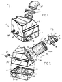
- System 10 for purifying raw air is shown according to a preferred embodiment of the present invention.
- System 10 includes an air induction assembly 60 coupled to a replaceable filter assembly 140, which is contained within a housing 12.
- a conduit shown as a snorkel 18
- the raw air is directed through filter assembly 140, is purified, and the resulting purified air is directed to an outlet 66 of air induction assembly 60.
- An arrow 188 shows the general directional flow of the air through air cleaner system 10.
- Air induction assembly 60 defines an airflow path for the purified air as indicated by arrow 188.
- Air induction assembly 60 includes a conduit (shown as tube 62) having an inlet 64 and outlet 66.
- Inlet 64 of tube 62 is positioned within the interior of housing 12.
- Outlet 66 of tube 62 extends from the exterior of housing 12.
- a fastener (shown as a capture clamp 162) secures a conduit (shown as a hose 160) to outlet 66 of tube 62.
- Hose 160 has an interior diameter 186 greater than an exterior diameter 180 of outlet 66.
- Hose 160 directs the purified air from outlet 66 to other engine systems (not shown) for processing (e.g., to a carburetor for the mixing of the purified air with fuel, and the eventual placement of the resulting mixture in the cylinder of an internal combustion engine).
- a mass airflow rate sensor assembly (shown as assembly 100) is mounted to the exterior of tube 62. Assembly 100 is positioned between an inward ridge 82 and an outward ridge 80 of tube 62. Assembly 100 includes an upper housing 112 secured to a lower housing 114 that encapsulate a mass airflow rate sensor 116 and a temperature sensor 118. Upper housing 112 and lower housing 114 may serve to protect sensor 116 and temperature sensor 118 from environmental factors (e.g., debris, water, heat, vibration, physical manipulation, damage during shipping, etc.).
- environmental factors e.g., debris, water, heat, vibration, physical manipulation, damage during shipping, etc.
- a detector capable of monitoring environmental variables (e.g., combustion air speed, air temperature, air density, air moisture, etc.) extends from lower housing 114 into the interior of tube 62.
- An electrical conductor (shown as a wire 120) connects assembly 100 to an engine system (not shown) such as a computer.
- assembly 100 may be integrally mounted to tube 62 and may be provided as a complete unit pre-calibrated to known variables related to tube 62 (such as engine size, air temperature, the geometry of tube 62, the distance between the periphery of tube 62 and the detector, etc.).
- a generally circular-shaped air filter element (shown as a canister 142) of filter assembly 140 is positioned within the interior of housing 12 and supported by a cradle 26.
- Canister 142 includes an air receiving surface (shown as an outer wall 150) and an air emitting surface (shown as an inner wall 152).
- a filter media 156 such as pretreated, pleated corrugated paper.
- impurities e.g., debris, particulates, gasses, dirt, pollution, etc.
- the purified air exits filter media 156 through inner wall 152 of canister 142.
- Filter assembly 140 also includes a generally "V"-shaped flexible, compressible seal 154 mounted to the upper portion canister 142. Seal 154 extends radially around an aperture 158 of canister 142.
- a fastener (not shown), such as an adhesive or glue, may secure seal 154 to canister 142, and may secure a left end 144 of filter media 156 to a right end 134 of filter media 156.
- seal 154 may be integrally molded to canister 142.
- canister 142 When system 10 is in a fully assembled condition (as shown in FIGURE 1), canister 142 is positioned within housing 12, and inlet 64 of tube 62 is positioned within canister 142.
- An outer diameter 190 of inlet 64 is less than a diameter 182 of an aperture 158 of canister 142.
- a diameter 184 of an aperture 52 of an upper shell 14 of housing 12 is greater than an outer diameter 192 of end cap 148, and outer diameter 190 of inlet 64 is less than diameter 182 of aperture 158 of canister 142. (See FIGURE 2.)
- a flange 68 integrally mounted to tube 62 extends about the periphery of tube 62.
- a housing connector system 40 of upper shell 14 secures filter assembly 140 to a conduit connector system 70 of flange 68.
- Housing connector system 40 and conduit connector system 70 may serve to compress seal 154 and form a closure or connection between filter assembly 140 and air induction assembly 60 such that air is inhibited from bypassing canister 142.
- Housing connector system 40 includes outwardly extending protrusions (shown as fingers 42) and inwardly extending indentations (shown as fingers 44) spaced generally evenly about the periphery of aperture 52 of upper shell 14.
- Conduit connector system 70 includes reciprocal outwardly extending protrusions (shown as fingers 72) and inwardly extending indentations (shown as fingers 74) spaced generally evenly about the periphery of flange 68 of tube 62. Conduit connector system 70 also includes a cover 76 positioned over fingers 74 (see FIGURE 4). To create the effective closure or connection between filter assembly 140 and air induction assembly 60, a compressive force is applied to air induction assembly 60 to compress seal 154 between a seal engaging surface 78 of flange 68 and canister 142. Fingers 72 of conduit connector system 70 are aligned with and inserted into fingers 44 of housing connector system 40.
- Tube 62 is rotated relative to upper shell 14 (or vice versa) such that fingers 72 of conduit connector system 70 are positioned below fingers 42 of housing connector system 40 (i.e., the fingers of the housing connector system and the conduit connector system are rotated until they are intertwined and interconnected) and cover 76 is positioned over fingers 44 of housing connector system 40.
- the compression of seal 154 and the interconnection of the fingers 42 and fingers 72 maintain such compressive force.
- a locking system 90 inhibits further rotation of tube 62 relative to upper shell 14 (such rotation may cause a disconnection between fingers 42 of housing connector system 40 and fingers 72 of conduit connector system 70).
- Locking system 90 includes a ramp 46 mounted to the exterior of upper shell 14 and positioned adjacent to the periphery of aperture 52.
- Ramp 46 includes an inclined surface 48 and a vertical surface 50, which is orthogonal to fingers 42 of upper shell 14.
- tube 62 is rotated relative to upper shell 14 (or vice versa) such that a glide 92 mounted to flange 68 slides over inclined surface 48 of ramp 46.
- Tube 62 is rotated until a catch 94 of glide 92 passes beyond vertical surface 50 of ramp 46.
- locking system 90 may include reinforcing tabs 98 to secure flange 68 to glide 92.
- housing 12 includes upper shell 14 mounted to a lower shell 16.
- Upper shell 14 includes a cavity (shown as a reservoir 194) and aperture 52 for receiving filter assembly 140 in reservoir 194.
- a downward sealing surface 20 engages an upward sealing surface 22 of lower shell 16.
- Lower shell 16 includes a cavity (shown as a reservoir 196) for the housing or encapsulation of filter assembly 140.
- a support structure (shown as cradle 26) provides support to canister 142.
- Cradle 26 includes a radial support (shown as a flange 28) and a transverse support (shown as a flange 30).
- a generally "U"-shaped indent 32 of flange 30 provides a surface upon which outer wall 150 of canister 142 may rest.
- a generally "V"-shaped indent 38 of flange 28 (having a bottom leg 34 and a side leg 36) provides a surface upon which the lower portion of canister 142 may rest, such that bottom leg 34 supports end cap 148 of canister 142 and side leg 36 supports outer wall 150 of canister 142.
- upper shell 14 may include apertures (not shown), which provide a convenient mounting point for mounting elements such as an air or fluid shock mounting (shown as a grommet 164).
- the exterior of the upper shell may include surface textures to provide additional support to the housing and to assist in the channeling of elements (e.g., air, water, debris, etc.) across the housing.
- the air cleaner system is used to purify raw air before the raw air is routed to an automotive or vehicular engine.
- the upper shell and the lower shell of the air cleaner system are preferably constructed of plastic that are vibration welded together at about 120 hertz.
- the hose mounted to the air induction assembly is preferably made of polyvinylchloride (PVC).
- the filter element is preferably constructed of paper folded in a zigzag configuration.
- the end cap is preferably constructed of aluminum metal and encapsulated in urethane.
- the seal is preferably generally "V"-shaped and constructed of urethane rubber.
- the accessory is preferably a mass airflow sensor, which measures the amount of raw air purified by the air cleaner, that is pre-calibrated to the geometry of the air induction assembly (e.g., by running a known airflow through the conduit and accounting for various environmental factors such as air speed, air temperature, the diameter of the conduit, the type of engine associated with the air induction assembly, etc.).
- conduit is not meant as a term of limitation, insofar as any valve, hose, tube or like structure providing a channel or passageway through which air may flow is intended to be included in the term.
- redirect is not meant as a term of limitation, insofar as any routing or leading of raw or purified air into, through and out of the air cleaner system is intended to be included in the term.
- engine system is not meant as a term of limitation, insofar as any "engine” or like machine for using fuel to produce motion or accompanying accessory (e.g., catalytic convert, carburetor, cylinder, fuel injection system, computer system, fan, etc.) is intended to be included in the term.
- engine e.g., catalytic convert, carburetor, cylinder, fuel injection system, computer system, fan, etc.
- the mounting of the upper shell and the lower shell of the housing may be replaced with such well known substitutions as an interlocking tab and slot arrangement (which would have the added benefit of permitting the upper shell to be removed entirely from the lower shell), the hinging of the upper shell to the lower shell (which would permit the shells to be pivotally opened and closed), or other suitable fastening devices (such as welding, ultrasonic welding, vibration welding, glue, screws, rivets, clamps or other conventional methods) or the housing may be provided as a single piece.
- the aperture in the upper shell may be provided in either or both of the shells.
- the filter element may be disposable.
- the filter material may be constructed of a porous material (e.g., cardboard, corrugated paper, carbon block, etc.) or a natural or synthetic fibrous material (e.g., spun polyethylene, glass wool, microbial filter, etc.).
- the effective closure or seal between the air induction assembly and the housing may be formed by any known connection system (such as a bayonet connector system, a threaded connection, a clamp, etc.) and may be maintained by any locking mechanism (e.g., a detent, a tumbler lock, a tacky adhesive, etc.).
- the seal may be mounted to the upper shell, fixed to a rigid or semi-rigid framework that also extends about the periphery of the filter element, or detached from both the upper shell and the filter element.
- the seal may be positioned between the filter and the air induction assembly or between the air induction assembly and the housing.
- the inlet of the air induction assembly may be positioned in close proximity to the filter element or a space may be provided between the inlet of the air induction assembly and the filter element.
- the filter element may be positioned in close proximity to the periphery of the aperture of the upper shell or a space may be provided between the filter element and the periphery of the aperture of the upper shell.
- the base of the lower shell may support the bottom portion of the filter element.
- the air induction assembly may be disposable or selectively removable from the filter assembly.
- a screen of geometric cells e.g., hexagonal cells
- a flow straighter may be provided within the conduit to inhibit the formation of undesirable airflow (e.g., eddies) around the detector.
- a vapor management valve may be provided in the flow path of the air induction assembly.
- the accessory may be permanently or removably mounted to the air induction assembly. Such mounting of the accessory may be integral (such as by the use of potting compounds or adhesives) or removable (such as by known fastening devices).
- the accessory and the detector may be mounted at any position on the conduit or may be positioned either upstream or downstream from the airflow path through the conduit.
Landscapes
- Engineering & Computer Science (AREA)
- Manufacturing & Machinery (AREA)
- Chemical & Material Sciences (AREA)
- Combustion & Propulsion (AREA)
- Mechanical Engineering (AREA)
- General Engineering & Computer Science (AREA)
- Filtering Of Dispersed Particles In Gases (AREA)
Priority Applications (1)
| Application Number | Priority Date | Filing Date | Title |
|---|---|---|---|
| EP00121507A EP1193389A1 (de) | 2000-09-29 | 2000-09-29 | Einrichtung zur Reiniging von Luft |
Applications Claiming Priority (1)
| Application Number | Priority Date | Filing Date | Title |
|---|---|---|---|
| EP00121507A EP1193389A1 (de) | 2000-09-29 | 2000-09-29 | Einrichtung zur Reiniging von Luft |
Publications (1)
| Publication Number | Publication Date |
|---|---|
| EP1193389A1 true EP1193389A1 (de) | 2002-04-03 |
Family
ID=8169994
Family Applications (1)
| Application Number | Title | Priority Date | Filing Date |
|---|---|---|---|
| EP00121507A Withdrawn EP1193389A1 (de) | 2000-09-29 | 2000-09-29 | Einrichtung zur Reiniging von Luft |
Country Status (1)
| Country | Link |
|---|---|
| EP (1) | EP1193389A1 (de) |
Cited By (2)
| Publication number | Priority date | Publication date | Assignee | Title |
|---|---|---|---|---|
| WO2002099267A1 (de) * | 2001-06-01 | 2002-12-12 | Robert Bosch Gmbh | Vorrichtung zur bestimmung zumindest eines parameters eines in einer leitung strömenden mediums mit einem filter zur aufnahme von schadstoffen in der leitung |
| EP2154358A1 (de) * | 2008-07-25 | 2010-02-17 | Mann+Hummel Gmbh | Luftfiltersystem eines Kraftfahrzeuges |
Citations (5)
| Publication number | Priority date | Publication date | Assignee | Title |
|---|---|---|---|---|
| US5106397A (en) * | 1990-12-26 | 1992-04-21 | Ford Motor Company | Air cleaner/noise silencer assembly |
| EP0515051A1 (de) * | 1991-05-23 | 1992-11-25 | Ford Motor Company Limited | Luftreiniger für eine Brennkraftmaschine |
| JPH1144264A (ja) * | 1997-07-28 | 1999-02-16 | Suzuki Motor Corp | 吸気装置 |
| EP0909890A2 (de) * | 1997-10-17 | 1999-04-21 | Ford Motor Company | Lufteinlassanordnung für Luftmassensensor |
| DE19836442A1 (de) * | 1998-08-12 | 2000-02-17 | Daimler Chrysler Ag | Vorrichtung zum Schutz einer in einer Ansaugleitung einer Brennkraftmaschine angeordneten Luftmassenmeßeinrichtung |
-
2000
- 2000-09-29 EP EP00121507A patent/EP1193389A1/de not_active Withdrawn
Patent Citations (5)
| Publication number | Priority date | Publication date | Assignee | Title |
|---|---|---|---|---|
| US5106397A (en) * | 1990-12-26 | 1992-04-21 | Ford Motor Company | Air cleaner/noise silencer assembly |
| EP0515051A1 (de) * | 1991-05-23 | 1992-11-25 | Ford Motor Company Limited | Luftreiniger für eine Brennkraftmaschine |
| JPH1144264A (ja) * | 1997-07-28 | 1999-02-16 | Suzuki Motor Corp | 吸気装置 |
| EP0909890A2 (de) * | 1997-10-17 | 1999-04-21 | Ford Motor Company | Lufteinlassanordnung für Luftmassensensor |
| DE19836442A1 (de) * | 1998-08-12 | 2000-02-17 | Daimler Chrysler Ag | Vorrichtung zum Schutz einer in einer Ansaugleitung einer Brennkraftmaschine angeordneten Luftmassenmeßeinrichtung |
Non-Patent Citations (1)
| Title |
|---|
| PATENT ABSTRACTS OF JAPAN vol. 1999, no. 05 31 May 1999 (1999-05-31) * |
Cited By (3)
| Publication number | Priority date | Publication date | Assignee | Title |
|---|---|---|---|---|
| WO2002099267A1 (de) * | 2001-06-01 | 2002-12-12 | Robert Bosch Gmbh | Vorrichtung zur bestimmung zumindest eines parameters eines in einer leitung strömenden mediums mit einem filter zur aufnahme von schadstoffen in der leitung |
| EP2154358A1 (de) * | 2008-07-25 | 2010-02-17 | Mann+Hummel Gmbh | Luftfiltersystem eines Kraftfahrzeuges |
| US8241413B2 (en) | 2008-07-25 | 2012-08-14 | Mann+Hummel Gmbh | Air filter system of a motor vehicle |
Similar Documents
| Publication | Publication Date | Title |
|---|---|---|
| US6167862B1 (en) | Air cleaner system | |
| US5125940A (en) | In-line air filter apparatus | |
| US9334771B2 (en) | Filter unit in a filter housing | |
| CN108348830B (zh) | 过滤器元件和过滤器装置 | |
| US20050217625A1 (en) | Heat shielded air intake system | |
| US20070079794A1 (en) | Air cleaner assembly | |
| EP1650426B1 (de) | Nutzfahrzeug | |
| US6355077B1 (en) | Air filter having integrated sealing orifice | |
| US7927393B2 (en) | Air cleaner element | |
| WO2006137518A1 (ja) | エンジンのエアクリーナおよびエンジンへのエアクリーナ取付装置 | |
| US20230213008A1 (en) | High performance air intake system | |
| US6293981B1 (en) | Arrangement of an air filter and a membrane carburetor | |
| US11649792B2 (en) | Snow bike intake | |
| US20070144154A1 (en) | Air filter with air flow segregation | |
| US8876931B2 (en) | Filter assembly | |
| EP1193389A1 (de) | Einrichtung zur Reiniging von Luft | |
| RU144907U1 (ru) | Впускная система для двигателя | |
| CN206129556U (zh) | 改进的空气滤清器 | |
| US6162269A (en) | Filter assembly for cleaning cooling air for engines | |
| JPS6313417Y2 (de) | ||
| KR102285758B1 (ko) | 인라인(in-line) 또는 인렛(inlet)에 활용되는 필터 | |
| JPH11173226A (ja) | 内燃機関の吸気装置 | |
| CN216198541U (zh) | 一种机车空气滤清器 | |
| JP3643498B2 (ja) | エアークリーナ | |
| KR200143020Y1 (ko) | 오버헤드가드에 부설된 공기흡입구 |
Legal Events
| Date | Code | Title | Description |
|---|---|---|---|
| PUAI | Public reference made under article 153(3) epc to a published international application that has entered the european phase |
Free format text: ORIGINAL CODE: 0009012 |
|
| 17P | Request for examination filed |
Effective date: 20010409 |
|
| AK | Designated contracting states |
Kind code of ref document: A1 Designated state(s): DE FR GB Kind code of ref document: A1 Designated state(s): AT BE CH CY DE DK ES FI FR GB GR IE IT LI LU MC NL PT SE |
|
| AX | Request for extension of the european patent |
Free format text: AL;LT;LV;MK;RO;SI |
|
| AKX | Designation fees paid |
Free format text: DE FR GB |
|
| RIN1 | Information on inventor provided before grant (corrected) |
Inventor name: SETESCAK, STEPHEN E. Inventor name: BLOOMER, STEPHEN F. Inventor name: POWELL, JEFFREY J. |
|
| RAP1 | Party data changed (applicant data changed or rights of an application transferred) |
Owner name: SIEMENS VDO AUTOMOTIVE INC. |
|
| STAA | Information on the status of an ep patent application or granted ep patent |
Free format text: STATUS: THE APPLICATION HAS BEEN WITHDRAWN |
|
| 18W | Application withdrawn |
Effective date: 20010105 |
|
| R18W | Application withdrawn (corrected) |
Effective date: 20040105 |