EP1193384B1 - Device and method for controlling an electromagnet controlling a metering valve of an internal combustion engine fuel injector - Google Patents
Device and method for controlling an electromagnet controlling a metering valve of an internal combustion engine fuel injector Download PDFInfo
- Publication number
- EP1193384B1 EP1193384B1 EP01122654A EP01122654A EP1193384B1 EP 1193384 B1 EP1193384 B1 EP 1193384B1 EP 01122654 A EP01122654 A EP 01122654A EP 01122654 A EP01122654 A EP 01122654A EP 1193384 B1 EP1193384 B1 EP 1193384B1
- Authority
- EP
- European Patent Office
- Prior art keywords
- temperature
- engine
- electromagnet
- current
- duration
- Prior art date
- Legal status (The legal status is an assumption and is not a legal conclusion. Google has not performed a legal analysis and makes no representation as to the accuracy of the status listed.)
- Expired - Lifetime
Links
- 239000000446 fuel Substances 0.000 title claims description 20
- 238000000034 method Methods 0.000 title claims description 11
- 238000002485 combustion reaction Methods 0.000 title claims description 6
- 239000000498 cooling water Substances 0.000 claims description 5
- 239000010687 lubricating oil Substances 0.000 claims description 5
- 230000005284 excitation Effects 0.000 description 10
- 230000007423 decrease Effects 0.000 description 5
- 230000003247 decreasing effect Effects 0.000 description 4
- 230000007704 transition Effects 0.000 description 3
- 238000010586 diagram Methods 0.000 description 1
- 239000002828 fuel tank Substances 0.000 description 1
- 238000002347 injection Methods 0.000 description 1
- 239000007924 injection Substances 0.000 description 1
- 230000001788 irregular Effects 0.000 description 1
- 239000000463 material Substances 0.000 description 1
Images

Classifications
-
- F—MECHANICAL ENGINEERING; LIGHTING; HEATING; WEAPONS; BLASTING
- F02—COMBUSTION ENGINES; HOT-GAS OR COMBUSTION-PRODUCT ENGINE PLANTS
- F02D—CONTROLLING COMBUSTION ENGINES
- F02D41/00—Electrical control of supply of combustible mixture or its constituents
- F02D41/20—Output circuits, e.g. for controlling currents in command coils
- F02D2041/2003—Output circuits, e.g. for controlling currents in command coils using means for creating a boost voltage, i.e. generation or use of a voltage higher than the battery voltage, e.g. to speed up injector opening
- F02D2041/2013—Output circuits, e.g. for controlling currents in command coils using means for creating a boost voltage, i.e. generation or use of a voltage higher than the battery voltage, e.g. to speed up injector opening by using a boost voltage source
-
- F—MECHANICAL ENGINEERING; LIGHTING; HEATING; WEAPONS; BLASTING
- F02—COMBUSTION ENGINES; HOT-GAS OR COMBUSTION-PRODUCT ENGINE PLANTS
- F02D—CONTROLLING COMBUSTION ENGINES
- F02D41/00—Electrical control of supply of combustible mixture or its constituents
- F02D41/20—Output circuits, e.g. for controlling currents in command coils
- F02D2041/202—Output circuits, e.g. for controlling currents in command coils characterised by the control of the circuit
- F02D2041/2031—Control of the current by means of delays or monostable multivibrators
-
- F—MECHANICAL ENGINEERING; LIGHTING; HEATING; WEAPONS; BLASTING
- F02—COMBUSTION ENGINES; HOT-GAS OR COMBUSTION-PRODUCT ENGINE PLANTS
- F02D—CONTROLLING COMBUSTION ENGINES
- F02D2200/00—Input parameters for engine control
- F02D2200/02—Input parameters for engine control the parameters being related to the engine
- F02D2200/06—Fuel or fuel supply system parameters
- F02D2200/0606—Fuel temperature
Definitions
- the present invention relates to a device and method for controlling an electromagnet controlling a metering valve of an internal combustion engine fuel injector.
- a metering valve is normally opened by exciting an electromagnet controlling the valve. Excitation of the electromagnet commences at a given instant depending on the stroke of the corresponding engine cylinder, and is effected by a first current. After a given delay, sufficient to ensure the valve is opened completely, the first current is replaced by a second current, which is lower, e.g. about half, the first current, to simply keep the electromagnet excited and the valve open. The instant the second current ceases depends on the amount of fuel required by the engine, so that the total excitation time of the electromagnet depends on the operating conditions, e.g. speed, torque, etc., of the engine.
- the decay time of the magnetic field of the coil varies with time, so that the electromagnet is excited by a current whose time graph, as of the first instant, comprises a portion increasing rapidly to a substantially constant first current, a portion decreasing to a lower second current from another instant having a predetermined delay with respect to the first, and a portion in which the second current decreases to zero from a second instant.
- the delay is selected to ensure the valve opens in any condition, in particular with any engine and fuel temperature, and is therefore fairly long.
- the transition in the excitation of the electromagnet, from the higher to the lower current, results in nonlinearity of the quantity of fuel injected as a function of excitation time.
- nonlinearity frequently occurs at a critical point in the operation of the engine, thus resulting in irregular power output.
- a device for controlling an electromagnet controlling a metering valve of a fuel injector of an internal combustion engine which comprises an electric circuit for generating a first electric current of such a predetermined value as to excite said electromagnet to open said metering valve; said electric circuit generating a second electric current of a value lower than said predetermined value and such as to keep said electromagnet so excited; timing means being provided to control said electric circuit as a function of operating conditions of said engine in such a manner as to vary the duration of said first current as a function of the operating temperature of said engine; characterized in that said electric circuit is controlled by an electric signal emitted by a temperature-indicating circuit as a function of the temperature detected by at least two of the following sensors: a sensor for detecting the temperature of the cooling water of the engine; a sensor for detecting the temperature of the lubricating oil of the engine; a sensor for detecting the temperature of the fuel to be injected by the injector.
- the electromagnet is firstly excited by a first electric current of such a predetermined value as to excite said electromagnet, and is subsequently kept excited by a second electric current of a value lower than said predetermined value; the duration of said first current being varied as a function of the operating temperature of said engine; characterized in that said duration is varied as a function of the temperature detected from at least two of the following heat sources: the cooling water of the engine; the lubricating oil of the engine; the fuel to be injected by the injector.
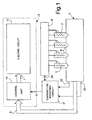
- Number 5 in Figure 1 indicates as a whole an internal combustion engine, e.g. a diesel engine, having a number of cylinders, each supplied with high-pressure fuel by a known injector 6.
- Each injector 6 is activated by a metering valve controlled by a corresponding electromagnet 7. More specifically, injectors 6 are connected to a common fuel vessel or so-called “common rail" 8 to which fuel is pumped from the usual fuel tank.
- Electromagnets 7 are controlled by a control device, indicated as a whole by 9, which comprises an electric circuit 11 controlled by timing means, e.g. an electronic control unit 12, as a function of the operating conditions of engine 5.
- control unit 12 receives information signals S measured on engine 5 - e.g. engine speed, required power or torque, the stroke of each cylinder - and generates timing signals t which are used by circuit 11 to control electromagnets 7.
- electric circuit 11 To control each electromagnet 7, electric circuit 11 generates a first electric current 13 ( Figure 2) of such a predetermined value as to excite each electromagnet 7 to open the metering valve; and a second electric current 14 of a value lower than that of current 13, and which keeps electromagnet 7 excited at minimum energy cost. After a given duration of first current 13, second current 14 is therefore substituted for the first to keep the metering valve open.
- First current 13 may advantageously be of a mean value of about 20 A, and second current 14 of about 10 A.
- Electric circuit 11 may be of the type described in the Applicant's Italian Patent Application n° TO96A000637 , in which the control unit defines a first instant t1 at which excitation of electromagnet 7 commences, a second instant t2 at which excitation is terminated, and an intermediate instant t3 at which first current 13 is terminated.
- the Figure 2 graph shows the excitation current I of electromagnet 7 as a function of time t, and comprises, as of first instant t1, a portion 16 increasing rapidly to a value defining first current 13, which actually increases slightly, on account of the structure of selected circuit 11.
- the current I graph comprises a portion 17 decreasing rapidly to a value defining second current 14, and, as of instant t2, another portion 18 in which second current 14 decreases rapidly to zero.
- the Figure 3 graph shows the quantity Q of fuel injected as a function of the excitation time of the electromagnet.
- portion 17 creates a transition in the excitation of electromagnet 7, from higher current 13 to lower current 14, which produces a portion 19 in which a nonlinear quantity Q of fuel is injected as a function of excitation time.
- instant t3 must be selected to ensure the metering valve opens in any temperature and operating condition of the engine, so that delay t3-t1 is extremely long, and nonlinearity portion 19 often occurs at a critical point in the operation of the engine. For example, at idling speed, instant t2 may occur before current I reaches the current 14 value, thus increasing the duration of portion 18.
- control unit 12 controls electric circuit 11 to vary the duration of current 13 as a function of the operating temperature of engine 5. More specifically, control device 9 comprises a temperature-indicating circuit 21, which emits an electric temperature signal T as a function of the temperatures detected by sensors at one or more points on engine 5, e.g. as a function of the mean of said temperatures; and signal T is processed by control unit 12 to determine instant t3, i.e. the duration of higher current 13.
- circuit 21 receives a signal from a sensor 22 for detecting the cooling water temperature of engine 5; a signal from an engine lubricating oil temperature sensor 23; and a signal from a fuel temperature sensor 24 located, for example, in the common rail.
- the signal T emitted by circuit 21 may indicate the mean of the temperatures detected by sensors 22-24. In winter and when engine 5 is cold, the above temperatures are obviously much lower than in summer and when engine 5 is running steadily.
- control unit 12 varies instant t3 so that the duration of first current 13 is maximum when signal T indicates a temperature of -40°C or lower, is minimum when signal T indicates a temperature of -10°C or higher, and is thus increased appropriately at low temperatures.
- Figure 4 shows a graph of duration t3-t1 as a function of the temperature indicated by signal T, and which varies from a maximum of about 400 ⁇ sec to a minimum ranging between 250 and 150 ⁇ sec, depending on the type of injection system on which control device 9 is used.
- the dash line indicates the portion 17' in which first current 13 decreases in the case of a temperature of -40°C or lower
- the dot-and-dash lines indicate the portions 17" in which current 13 decreases, and in which the decrease may vary, in the case of a temperature of -10°C or higher.
- Instant t3 determining portion 17' is preferably such that decreasing portion 17' does not exceed decreasing portion 18 of second current 14 in any operating condition of engine 5.
- Control device 9 therefore implements a method of controlling an electromagnet 7 controlling the metering valve of a fuel injector 6, in which electromagnet 7 is first excited by a first electric current 13 of such a predetermined value as to excite electromagnet 7 to open the metering valve, and is subsequently kept excited by a lower second electric current 14 to keep the metering valve open; the duration t3-t1 of first current 13 being varied as a function of the operating temperature of engine 5.
- the duration of current 13 is reduced at temperatures over -10°C, so that, even when engine 5 is idling, instant t2 never occurs at the transition point in the operation of engine 5.
Landscapes
- Engineering & Computer Science (AREA)
- Chemical & Material Sciences (AREA)
- Combustion & Propulsion (AREA)
- Mechanical Engineering (AREA)
- General Engineering & Computer Science (AREA)
- Fuel-Injection Apparatus (AREA)
- Electrical Control Of Air Or Fuel Supplied To Internal-Combustion Engine (AREA)
- Sewage (AREA)
Applications Claiming Priority (2)
| Application Number | Priority Date | Filing Date | Title |
|---|---|---|---|
| IT2000TO000911A IT1320679B1 (it) | 2000-09-29 | 2000-09-29 | Dispositivo di controllo di un elettromagnete di comando di unavalvola di dosaggio di un iniettore di combustibile per un motore a |
| ITTO000911 | 2000-09-29 |
Publications (3)
| Publication Number | Publication Date |
|---|---|
| EP1193384A2 EP1193384A2 (en) | 2002-04-03 |
| EP1193384A3 EP1193384A3 (en) | 2003-07-30 |
| EP1193384B1 true EP1193384B1 (en) | 2007-09-26 |
Family
ID=11458075
Family Applications (1)
| Application Number | Title | Priority Date | Filing Date |
|---|---|---|---|
| EP01122654A Expired - Lifetime EP1193384B1 (en) | 2000-09-29 | 2001-09-27 | Device and method for controlling an electromagnet controlling a metering valve of an internal combustion engine fuel injector |
Country Status (5)
| Country | Link |
|---|---|
| US (1) | US6578556B2 (it) |
| EP (1) | EP1193384B1 (it) |
| AT (1) | ATE374312T1 (it) |
| DE (1) | DE60130612T2 (it) |
| IT (1) | IT1320679B1 (it) |
Families Citing this family (5)
| Publication number | Priority date | Publication date | Assignee | Title |
|---|---|---|---|---|
| JP4380765B2 (ja) * | 2007-12-21 | 2009-12-09 | 株式会社デンソー | 内燃機関の制御装置 |
| DE102008042265A1 (de) * | 2008-09-22 | 2010-04-08 | Robert Bosch Gmbh | Verfahren zum Betreiben eines Einspritzventils |
| JP6314733B2 (ja) * | 2014-08-06 | 2018-04-25 | 株式会社デンソー | 内燃機関の燃料噴射制御装置 |
| JP6393649B2 (ja) | 2015-03-31 | 2018-09-19 | 株式会社クボタ | ディーゼルエンジンの噴射制御装置 |
| AT516756B1 (de) * | 2015-07-10 | 2016-08-15 | Waldland Naturstoffe Gmbh | Direkteinspritzende selbstzündende Brennkraftmaschine |
Family Cites Families (9)
| Publication number | Priority date | Publication date | Assignee | Title |
|---|---|---|---|---|
| DE19503536A1 (de) * | 1995-02-03 | 1996-08-08 | Bosch Gmbh Robert | Schaltungsanordnung für ein Einrückrelais |
| IT1284693B1 (it) * | 1996-07-23 | 1998-05-21 | Fiat Ricerche | Dispositivo di controllo di carichi induttivi, in paricolare di iniettori in un impianto di iniezione per un motore a combustione |
| JP2963407B2 (ja) * | 1997-02-14 | 1999-10-18 | 本田技研工業株式会社 | 燃料噴射弁制御装置 |
| JPH11148439A (ja) * | 1997-06-26 | 1999-06-02 | Hitachi Ltd | 電磁式燃料噴射弁及びその燃料噴射方法 |
| DE19735560B4 (de) * | 1997-08-16 | 2007-06-21 | Robert Bosch Gmbh | Verfahren und Vorrichtung zur Steuerung eines Verbrauchers |
| JPH11200918A (ja) * | 1997-11-17 | 1999-07-27 | Denso Corp | 内燃機関の燃料噴射制御装置 |
| US6014956A (en) * | 1997-12-22 | 2000-01-18 | Caterpillar Inc. | Electronic control for a hydraulically activated, electronically controlled injector fuel system and method for operating same |
| DE19833830A1 (de) * | 1998-07-28 | 2000-02-03 | Bosch Gmbh Robert | Verfahren und Vorrichtung zur Steuerung wenigstens eines Magnetventils |
| DE19922971A1 (de) * | 1999-05-19 | 2000-11-23 | Fev Motorentech Gmbh | Verfahren zur Inbetriebnahme eines elektromagnetischen Aktuators zur Betätigung eines Gaswechselventils an einer Kolbenbrennkraftmaschine |
-
2000
- 2000-09-29 IT IT2000TO000911A patent/IT1320679B1/it active
-
2001
- 2001-09-27 AT AT01122654T patent/ATE374312T1/de not_active IP Right Cessation
- 2001-09-27 EP EP01122654A patent/EP1193384B1/en not_active Expired - Lifetime
- 2001-09-27 DE DE60130612T patent/DE60130612T2/de not_active Expired - Lifetime
- 2001-09-28 US US09/966,770 patent/US6578556B2/en not_active Expired - Lifetime
Also Published As
| Publication number | Publication date |
|---|---|
| ATE374312T1 (de) | 2007-10-15 |
| EP1193384A3 (en) | 2003-07-30 |
| US20020066438A1 (en) | 2002-06-06 |
| EP1193384A2 (en) | 2002-04-03 |
| US6578556B2 (en) | 2003-06-17 |
| DE60130612T2 (de) | 2008-07-03 |
| ITTO20000911A1 (it) | 2002-03-29 |
| IT1320679B1 (it) | 2003-12-10 |
| ITTO20000911A0 (it) | 2000-09-29 |
| DE60130612D1 (de) | 2007-11-08 |
Similar Documents
| Publication | Publication Date | Title |
|---|---|---|
| JP5053868B2 (ja) | 燃料噴射制御装置 | |
| US6014955A (en) | Control apparatus for internal combustion engine using air-amount-first fuel-amount-second control method | |
| US5070836A (en) | Method and arrangement for controlling the injection of fuel in an internal combustion engine | |
| JP3871375B2 (ja) | 内燃機関の燃料噴射装置 | |
| EP1900930A1 (en) | Method and apparatus for pressure reducing valve to reduce fuel pressure in a common rail | |
| US6152107A (en) | Device for controlling fuel injection in cold engine temperatures | |
| US6518763B2 (en) | Control system for metering fuel to an internal combustion engine | |
| US8332125B2 (en) | Method for controlling at least one solenoid valve | |
| EP1193384B1 (en) | Device and method for controlling an electromagnet controlling a metering valve of an internal combustion engine fuel injector | |
| US5901682A (en) | Method for transitioning between different operating modes of an internal combustion engine | |
| KR920003131A (ko) | 솔레노이드 작동기의 제어방법 및 장치 | |
| DE59914318D1 (de) | Steuereinrichtung für Verbrennungsmotoren | |
| JP5253529B2 (ja) | エンジン出力損失の補償 | |
| EP1074721B1 (en) | Engine fuel injection control device | |
| US5101797A (en) | Control system for a diesel internal combustion engine | |
| GB2329525A (en) | A control system for an electromagnetic solenoid device | |
| Yang et al. | Study of the injection control valve in a new electronic diesel fuel system | |
| JP3864525B2 (ja) | エンジン燃料供給診断装置および方法 | |
| Glasmachers et al. | Sensorless movement control of solenoid fuel injectors | |
| JP2002013435A (ja) | 電磁的負荷を制御する方法および装置 | |
| JP4735621B2 (ja) | 噴射量学習装置 | |
| US6196190B1 (en) | Method for determining an operating parameter for starting an internal combustion engine | |
| KR100360799B1 (ko) | 자동차용 인젝터의 노화를 보상하는 인젝터맵 적용방법 | |
| JP2005163549A (ja) | インジェクタ駆動装置 | |
| US20030196642A1 (en) | Method and device for controlling fuel metering into an internal combustion engine |
Legal Events
| Date | Code | Title | Description |
|---|---|---|---|
| PUAI | Public reference made under article 153(3) epc to a published international application that has entered the european phase |
Free format text: ORIGINAL CODE: 0009012 |
|
| AK | Designated contracting states |
Kind code of ref document: A2 Designated state(s): AT BE CH CY DE DK ES FI FR GB GR IE IT LI LU MC NL PT SE TR |
|
| AX | Request for extension of the european patent |
Free format text: AL;LT;LV;MK;RO;SI |
|
| PUAL | Search report despatched |
Free format text: ORIGINAL CODE: 0009013 |
|
| AK | Designated contracting states |
Designated state(s): AT BE CH CY DE DK ES FI FR GB GR IE IT LI LU MC NL PT SE TR |
|
| AX | Request for extension of the european patent |
Extension state: AL LT LV MK RO SI |
|
| 17P | Request for examination filed |
Effective date: 20040120 |
|
| AKX | Designation fees paid |
Designated state(s): AT BE CH CY DE DK ES FI FR GB GR IE IT LI LU MC NL PT SE TR |
|
| 17Q | First examination report despatched |
Effective date: 20060419 |
|
| GRAP | Despatch of communication of intention to grant a patent |
Free format text: ORIGINAL CODE: EPIDOSNIGR1 |
|
| GRAS | Grant fee paid |
Free format text: ORIGINAL CODE: EPIDOSNIGR3 |
|
| GRAA | (expected) grant |
Free format text: ORIGINAL CODE: 0009210 |
|
| AK | Designated contracting states |
Kind code of ref document: B1 Designated state(s): AT BE CH CY DE DK ES FI FR GB GR IE IT LI LU MC NL PT SE TR |
|
| REG | Reference to a national code |
Ref country code: GB Ref legal event code: FG4D |
|
| REG | Reference to a national code |
Ref country code: CH Ref legal event code: EP |
|
| REF | Corresponds to: |
Ref document number: 60130612 Country of ref document: DE Date of ref document: 20071108 Kind code of ref document: P |
|
| REG | Reference to a national code |
Ref country code: IE Ref legal event code: FG4D |
|
| PG25 | Lapsed in a contracting state [announced via postgrant information from national office to epo] |
Ref country code: FI Free format text: LAPSE BECAUSE OF FAILURE TO SUBMIT A TRANSLATION OF THE DESCRIPTION OR TO PAY THE FEE WITHIN THE PRESCRIBED TIME-LIMIT Effective date: 20070926 |
|
| PG25 | Lapsed in a contracting state [announced via postgrant information from national office to epo] |
Ref country code: AT Free format text: LAPSE BECAUSE OF FAILURE TO SUBMIT A TRANSLATION OF THE DESCRIPTION OR TO PAY THE FEE WITHIN THE PRESCRIBED TIME-LIMIT Effective date: 20070926 |
|
| NLV1 | Nl: lapsed or annulled due to failure to fulfill the requirements of art. 29p and 29m of the patents act | ||
| PG25 | Lapsed in a contracting state [announced via postgrant information from national office to epo] |
Ref country code: BE Free format text: LAPSE BECAUSE OF FAILURE TO SUBMIT A TRANSLATION OF THE DESCRIPTION OR TO PAY THE FEE WITHIN THE PRESCRIBED TIME-LIMIT Effective date: 20070926 |
|
| REG | Reference to a national code |
Ref country code: CH Ref legal event code: PL |
|
| PG25 | Lapsed in a contracting state [announced via postgrant information from national office to epo] |
Ref country code: NL Free format text: LAPSE BECAUSE OF FAILURE TO SUBMIT A TRANSLATION OF THE DESCRIPTION OR TO PAY THE FEE WITHIN THE PRESCRIBED TIME-LIMIT Effective date: 20070926 Ref country code: MC Free format text: LAPSE BECAUSE OF NON-PAYMENT OF DUE FEES Effective date: 20070930 Ref country code: LI Free format text: LAPSE BECAUSE OF FAILURE TO SUBMIT A TRANSLATION OF THE DESCRIPTION OR TO PAY THE FEE WITHIN THE PRESCRIBED TIME-LIMIT Effective date: 20070926 Ref country code: GR Free format text: LAPSE BECAUSE OF FAILURE TO SUBMIT A TRANSLATION OF THE DESCRIPTION OR TO PAY THE FEE WITHIN THE PRESCRIBED TIME-LIMIT Effective date: 20071227 Ref country code: ES Free format text: LAPSE BECAUSE OF FAILURE TO SUBMIT A TRANSLATION OF THE DESCRIPTION OR TO PAY THE FEE WITHIN THE PRESCRIBED TIME-LIMIT Effective date: 20080106 Ref country code: CH Free format text: LAPSE BECAUSE OF FAILURE TO SUBMIT A TRANSLATION OF THE DESCRIPTION OR TO PAY THE FEE WITHIN THE PRESCRIBED TIME-LIMIT Effective date: 20070926 |
|
| PG25 | Lapsed in a contracting state [announced via postgrant information from national office to epo] |
Ref country code: PT Free format text: LAPSE BECAUSE OF FAILURE TO SUBMIT A TRANSLATION OF THE DESCRIPTION OR TO PAY THE FEE WITHIN THE PRESCRIBED TIME-LIMIT Effective date: 20080226 |
|
| PG25 | Lapsed in a contracting state [announced via postgrant information from national office to epo] |
Ref country code: SE Free format text: LAPSE BECAUSE OF FAILURE TO SUBMIT A TRANSLATION OF THE DESCRIPTION OR TO PAY THE FEE WITHIN THE PRESCRIBED TIME-LIMIT Effective date: 20071226 |
|
| PG25 | Lapsed in a contracting state [announced via postgrant information from national office to epo] |
Ref country code: DK Free format text: LAPSE BECAUSE OF FAILURE TO SUBMIT A TRANSLATION OF THE DESCRIPTION OR TO PAY THE FEE WITHIN THE PRESCRIBED TIME-LIMIT Effective date: 20070926 |
|
| PLBE | No opposition filed within time limit |
Free format text: ORIGINAL CODE: 0009261 |
|
| STAA | Information on the status of an ep patent application or granted ep patent |
Free format text: STATUS: NO OPPOSITION FILED WITHIN TIME LIMIT |
|
| GBPC | Gb: european patent ceased through non-payment of renewal fee |
Effective date: 20071226 |
|
| 26N | No opposition filed |
Effective date: 20080627 |
|
| PG25 | Lapsed in a contracting state [announced via postgrant information from national office to epo] |
Ref country code: IE Free format text: LAPSE BECAUSE OF NON-PAYMENT OF DUE FEES Effective date: 20070927 |
|
| PG25 | Lapsed in a contracting state [announced via postgrant information from national office to epo] |
Ref country code: GB Free format text: LAPSE BECAUSE OF NON-PAYMENT OF DUE FEES Effective date: 20071226 |
|
| PG25 | Lapsed in a contracting state [announced via postgrant information from national office to epo] |
Ref country code: CY Free format text: LAPSE BECAUSE OF FAILURE TO SUBMIT A TRANSLATION OF THE DESCRIPTION OR TO PAY THE FEE WITHIN THE PRESCRIBED TIME-LIMIT Effective date: 20070926 |
|
| PG25 | Lapsed in a contracting state [announced via postgrant information from national office to epo] |
Ref country code: LU Free format text: LAPSE BECAUSE OF NON-PAYMENT OF DUE FEES Effective date: 20070927 |
|
| PG25 | Lapsed in a contracting state [announced via postgrant information from national office to epo] |
Ref country code: TR Free format text: LAPSE BECAUSE OF FAILURE TO SUBMIT A TRANSLATION OF THE DESCRIPTION OR TO PAY THE FEE WITHIN THE PRESCRIBED TIME-LIMIT Effective date: 20070926 |
|
| PG25 | Lapsed in a contracting state [announced via postgrant information from national office to epo] |
Ref country code: IT Free format text: LAPSE BECAUSE OF NON-PAYMENT OF DUE FEES Effective date: 20070927 |
|
| PGRI | Patent reinstated in contracting state [announced from national office to epo] |
Ref country code: IT Effective date: 20110616 |
|
| REG | Reference to a national code |
Ref country code: FR Ref legal event code: PLFP Year of fee payment: 15 |
|
| REG | Reference to a national code |
Ref country code: FR Ref legal event code: PLFP Year of fee payment: 16 |
|
| REG | Reference to a national code |
Ref country code: FR Ref legal event code: PLFP Year of fee payment: 17 |
|
| REG | Reference to a national code |
Ref country code: FR Ref legal event code: PLFP Year of fee payment: 18 |
|
| PGFP | Annual fee paid to national office [announced via postgrant information from national office to epo] |
Ref country code: DE Payment date: 20200928 Year of fee payment: 20 Ref country code: FR Payment date: 20200928 Year of fee payment: 20 |
|
| PGFP | Annual fee paid to national office [announced via postgrant information from national office to epo] |
Ref country code: IT Payment date: 20200911 Year of fee payment: 20 |
|
| REG | Reference to a national code |
Ref country code: DE Ref legal event code: R071 Ref document number: 60130612 Country of ref document: DE |