EP1193130A2 - Deformable element and documentation system for deformable elements for use in a vehicle - Google Patents
Deformable element and documentation system for deformable elements for use in a vehicle Download PDFInfo
- Publication number
- EP1193130A2 EP1193130A2 EP01120927A EP01120927A EP1193130A2 EP 1193130 A2 EP1193130 A2 EP 1193130A2 EP 01120927 A EP01120927 A EP 01120927A EP 01120927 A EP01120927 A EP 01120927A EP 1193130 A2 EP1193130 A2 EP 1193130A2
- Authority
- EP
- European Patent Office
- Prior art keywords
- deformation
- deformation element
- identification
- vehicle
- elements
- Prior art date
- Legal status (The legal status is an assumption and is not a legal conclusion. Google has not performed a legal analysis and makes no representation as to the accuracy of the status listed.)
- Withdrawn
Links
Images


Classifications
-
- B—PERFORMING OPERATIONS; TRANSPORTING
- B60—VEHICLES IN GENERAL
- B60R—VEHICLES, VEHICLE FITTINGS, OR VEHICLE PARTS, NOT OTHERWISE PROVIDED FOR
- B60R21/00—Arrangements or fittings on vehicles for protecting or preventing injuries to occupants or pedestrians in case of accidents or other traffic risks
- B60R21/02—Occupant safety arrangements or fittings, e.g. crash pads
- B60R21/04—Padded linings for the vehicle interior ; Energy absorbing structures associated with padded or non-padded linings
-
- B—PERFORMING OPERATIONS; TRANSPORTING
- B60—VEHICLES IN GENERAL
- B60R—VEHICLES, VEHICLE FITTINGS, OR VEHICLE PARTS, NOT OTHERWISE PROVIDED FOR
- B60R21/00—Arrangements or fittings on vehicles for protecting or preventing injuries to occupants or pedestrians in case of accidents or other traffic risks
-
- B—PERFORMING OPERATIONS; TRANSPORTING
- B60—VEHICLES IN GENERAL
- B60R—VEHICLES, VEHICLE FITTINGS, OR VEHICLE PARTS, NOT OTHERWISE PROVIDED FOR
- B60R25/00—Fittings or systems for preventing or indicating unauthorised use or theft of vehicles
- B60R25/01—Fittings or systems for preventing or indicating unauthorised use or theft of vehicles operating on vehicle systems or fittings, e.g. on doors, seats or windscreens
- B60R25/04—Fittings or systems for preventing or indicating unauthorised use or theft of vehicles operating on vehicle systems or fittings, e.g. on doors, seats or windscreens operating on the propulsion system, e.g. engine or drive motor
-
- G—PHYSICS
- G01—MEASURING; TESTING
- G01V—GEOPHYSICS; GRAVITATIONAL MEASUREMENTS; DETECTING MASSES OR OBJECTS; TAGS
- G01V15/00—Tags attached to, or associated with, an object, in order to enable detection of the object
Landscapes
- Engineering & Computer Science (AREA)
- Mechanical Engineering (AREA)
- Physics & Mathematics (AREA)
- Life Sciences & Earth Sciences (AREA)
- General Life Sciences & Earth Sciences (AREA)
- General Physics & Mathematics (AREA)
- Geophysics (AREA)
- Fittings On The Vehicle Exterior For Carrying Loads, And Devices For Holding Or Mounting Articles (AREA)
Abstract
Die Erfindung betrifft ein Deformationselement (1) für die Verwendung in einem Fahrzeug, das mindestens ein passives, induktives Identifikationselement (2), das eine Nur-Lesefunktion aufweist, als integralen Bestandteil umfasst. Weiterhin bezieht sich die Erfindung auf ein Dokumentationssystem für Deformationselemente, das mindestens ein Deformationselement (1I, 1II) mit einem passiven, induktiven Identifikationselement (2I, 2II), das eine Nur-Lesefunktion aufweist, als integralen Bestandteil umfasst, und eine zentrale Einheit (14) aufweist, in der die in den einzelnen Identifikationselementen (2I, 2II) abgelegte Information abfragbar und bearbeitbar ist. <IMAGE>The invention relates to a deformation element (1) for use in a vehicle, which comprises at least one passive, inductive identification element (2), which has a read-only function, as an integral part. The invention also relates to a documentation system for deformation elements, which comprises at least one deformation element (1I, 1II) with a passive, inductive identification element (2I, 2II), which has a read-only function, as an integral part, and a central unit (14 ), in which the information stored in the individual identification elements (2I, 2II) can be queried and processed. <IMAGE>
Description
Die Erfindung betrifft Deformationselemente und ein Dokumentationssystem für Deformationselemente zur Verwendung in einem Fahrzeug.The invention relates to deformation elements and a documentation system for deformation elements for use in a vehicle.
Bei Fahrzeugen werden eine Reihe von Bauelementen eingesetzt, die zur Erfüllung von Sicherheitskriterien, insbesondere bei Crash-Situationen, dienen sollen. Diese Bauelemente sind so ausgestaltet, dass sie bei einer Crash-Situation, beispielsweise einem Auffahrunfall, zumindest einen Teil der Aufprall-Energie aufnehmen können und damit Verletzungen von Insassen weitgehend verhindern können. Solche Deformationselemente werden beispielsweise im Bereich des hinteren Dachrahmens eingesetzt, um die Kopfaufschlagkriterien nach FMVSS 201 mit ausreichender Sicherheit erfüllen zu können. Nach FMVSS 201 muss die Kopfbelastung, gemessen am HIC(d) (Head Injury Criterion), beim Aufprall einer Kopfform auf bestimmte Punkte im Fahrzeuginnenraum kleiner als 1000 sein.A number of components are used in vehicles, the to meet safety criteria, especially in crash situations, should serve. These components are designed so that they in a crash situation, for example a rear-end collision, at least can absorb part of the impact energy and thus Can largely prevent injuries to occupants. Such Deformation elements are, for example, in the area of the rear Roof frame used to the head impact criteria according to FMVSS 201 with sufficient certainty. According to FMVSS 201 the head load, measured by the HIC (d) (Head Injury Criterion), when a head shape hits certain points in the Vehicle interior must be less than 1000.
Solche Elemente bestehen herkömmlicherweise aus unterschiedlichen Kunststoffschäumen (z.B. EPP oder PU), allerdings finden auch Rippenpakete aus spritzgegossenem Kunststoff, Metallwaben, Flexrohre, Deformationsbleche und dergleichen Verwendung. Aufgrund der steigenden Zahl der Deformationselemente wird eine Dokumentation in der Montage (beim Lieferanten oder beim Hersteller des Fahrzeuges) immer schwieriger. Es ist allerdings für die Sicherheit der Passagiere und aus haftungsrechtlicher Sicht für den Hersteller von Fahrzeugen unerlässlich, eine lückenlose Dokumentation zu erstellen. Nachdem die Fahrzeuge fertig gestellt wurden, ist es nicht mehr möglich, das Vorhandensein und den korrekten Einbau der Deformationselemente mit optischen Mitteln zu überprüfen, da die Elemente meist verdeckt eingebaut werden. Beim Einbau kann es aber beispielsweise dazu kommen, dass Deformationselemente, die gar nicht für eine bestimmte Position vorgesehen waren, dennoch in diese eingebaut werden. So werden teilweise zu kleine Deformationselemente eingebaut, oder zu große Deformationselemente werden in die falsche Position hineingepresst. Solche Fehler müssen auch nach dem Einbau noch kontrollierbar sein.Such elements traditionally consist of different ones Plastic foams (e.g. EPP or PU), but there are also rib packages made of injection molded plastic, metal honeycomb, flexible tubes, Deformation sheets and the like use. Because of the rising Number of deformation elements is documented in the Assembly (at the supplier or the manufacturer of the vehicle) always more difficult. However, it is for the safety of passengers and out liability law essential for the manufacturer of vehicles, to create a complete documentation. After the vehicles have been completed, it is no longer possible to have the presence and the correct installation of the deformation elements with optical means check, since the elements are mostly concealed. At the Installation, however, can lead to deformation elements, that were not intended for a specific position, nevertheless be built into this. So sometimes they become too small Deformation elements installed, or too large deformation elements are pressed into the wrong position. Such mistakes must be controllable even after installation.
Der Erfindung liegt daher die Aufgabe zugrunde ein Deformationselement zu schaffen, das einfach herzustellen ist und es erlaubt, dieses auch nach dem Einbau zu identifizieren und die Zugehörigkeit von Daten zu dem Deformationselement sicherzustellen.The invention is therefore based on the object of a deformation element to create that is easy to make and allows this even after installation to identify and the affiliation of data to ensure the deformation element.
Der Erfindung liegt die Erkenntnis zugrunde, dass diese Aufgabe durch ein Deformationselement gelöst werden kann, das eine berührungslose Identifikation erlaubt, das in herkömmlicherweise hergestellt werden kann und eine Veränderung der Identifikationsmerkmale nicht zulässt.The invention is based on the finding that this object is achieved by a deformation element can be solved, which is a non-contact Identification allows that to be manufactured in a conventional manner can and does not allow a change in the identification features.
Diese Aufgabe wird erfindungsgemäß durch ein Deformationselement für die Verwendung in einem Fahrzeug gelöst, das mindestens ein passives, induktives Identifikationselement, das eine Nur-Lesefunktion aufweist, als integralen Bestandteil umfasst. Als Deformationselemente werden solche Fahrzeugteile bezeichnet, die energieabsorbierende Aufprallelemente, z.B. in den Türen, sowie verstärkten Karosseriestrukturen an Seitenschwellen und Dachsäulen, darstellen. Diese Teile werden auch als Paddings bezeichnet. Das erfindungsgemäße Deformationselement weist als einen integralen Bestandteil ein Identifikationselement auf. This object is achieved by a deformation element for solved the use in a vehicle that has at least one passive, inductive identification element, which has a read-only function, included as an integral part. As deformation elements refers to such vehicle parts, the energy absorbing impact elements, e.g. in the doors, as well as reinforced body structures Side thresholds and roof pillars. These parts are too referred to as paddings. The deformation element according to the invention has an identification element as an integral part.
Dieses ist somit unverlierbar mit dem Deformationselement verbunden. Es ist daher nicht möglich, das Identifikationselement ohne Zerstörung des Deformationselementes zu entfernen. Dadurch wird sichergestellt, dass eine Manipulation, z.B. der Austausch von Identifikationselementen, verhindert werden kann.This is therefore captively connected to the deformation element. It is therefore not possible to destroy the identification element to remove the deformation element. This ensures that manipulation, e.g. the exchange of identification elements, can be prevented.
Weiterhin ist das Identifikationselement gemäß der Erfindung so ausgelegt, dass es eine Nur-Lese- (Read only-) Funktion aufweist, d.h. dass gegebenenfalls in dem Identifikationselement gespeicherte Daten nur abgefragt werden können, oder das Identifikationselement auf andere Art, z.B. aufgrund seiner Beschaffenheit, Auskunft über das Deformationselement, in dem es integriert ist, gibt. Hingegen ist es bei dem Identifikationselement gemäß der Erfindung nicht möglich, dieses und die gegebenenfalls darauf gespeicherten Daten zu verändern oder weitere Daten nach Fertigstellung des Deformationselementes darauf abzulegen. Dem Identifikationselement werden bei der Herstellung des Deformationselements Daten zugeordnet, die entweder darauf gespeichert, oder durch Aufnahme in eine Liste, in der ein Bezug zwischen dem Identifikationselement und den Merkmalen des Deformationselementes hergestellt wird, dokumentiert werden. Dieses Identifikationselement wird dann in das entsprechende Deformationselement eingebracht. Nach der Fertigstellung des Deformationselementes ist es somit weder für den Fahrzeughersteller, noch für z.B. den Kundendienst möglich, die Daten - eventuell versehentlich - zu ändern. Da das Identifikationselement einen integralen Bestandteil des Deformationselementes darstellt, wird das Identifikationselement bereits während der Fertigung des Deformationselementes in dieses ein- bzw. aufgebracht. Im Gegensatz zu Identifikationselementen, die während der Montage eines Fahrzeuges auf bereits fertiggestellte Deformationselemente aufgebracht werden, ist eine versehentliche fehlerhafte Zuordnung eines Identifikationselementes zu einem Deformationselement bei dem erfindungsgemäßen Deformationselement ausgeschlossen. Diese Sicherung der Daten und deren Zuordnung zu Deformationselementen ist aus sicherheitstechnischen Gründen unerlässlich. Es ist gleichzeitig aufgrund der passiven Ausführung des Identifikationselementes nicht notwendig, eine Stromversorgung für das Identifikationselement in dem Deformationselement vorzusehen. Das Identifikationselement ist als Informationsträger ausgestaltet, das passiv agiert, d.h. von dem Daten oder Informationen abgerufen werden, das aber diese nicht ohne äußere Anregung abgeben muss. Das Vorsehen einer Energieversorgung in dem Deformationselement ist daher bei dem erfindungsgemäß verwendeten passiven Identifikationselement nicht notwendig. Somit kann das Identifikationselement eine sehr geringe Größe aufweisen und beeinflusst damit die Eigenschaften, insbesondere die Fähigkeit des Deformationselementes zur Energieabsoprtion nicht maßgeblich.Furthermore, the identification element according to the invention is designed so that it has a read only function, i.e. that possibly only data stored in the identification element can be queried, or the identification element to others Type, e.g. due to its nature, information about the deformation element, in which it is integrated. On the other hand, it is with the identification element not possible according to the invention, this and the possibly change data stored on it or other data Store data on it after completion of the deformation element. The identification element is used in the manufacture of the deformation element Data associated with it, either stored on it, or by listing it in a relationship between the identification element and the features of the deformation element will be documented. This identification element is then in the corresponding deformation element is introduced. After completion of the deformation element, it is therefore neither for the Vehicle manufacturer, still for e.g. customer service possible, the data - possibly accidentally - to change. Since the identification element represents an integral part of the deformation element, that Identification element already during the production of the deformation element inserted into this or applied. Unlike identification elements, that already during the assembly of a vehicle Completed deformation elements applied is an accidental incorrect assignment of an identification element to a Deformation element in the deformation element according to the invention locked out. This backup of the data and their assignment to Deformation elements are essential for safety reasons. It is also due to the passive execution of the Identification element not necessary, a power supply for the To provide identification element in the deformation element. The Identification element is designed as an information carrier, the passive acts, i.e. from which data or information is retrieved but this does not have to be given without external stimulus. The provision an energy supply in the deformation element is therefore in the not used passive identification element according to the invention necessary. The identification element can thus be very small Have size and thus affects the properties, in particular the ability of the deformation element to absorb energy essential.
In einer Ausführungsform ist das Identifikationselement in dem Deformationselement unlösbar eingeschäumt. Bei Deformationselementen, die zur Energieabsorption meist aus Kunststoff, insbesondere Kunststoffschäumen bestehen, kann das Identifikationselement, gegebenenfalls nach dem Einspeichern von Daten, bei der Herstellung in das Deformationselement eingebracht werden. Es kann somit von äußeren Krafteinwirkungen und Temperaturänderungen während des Einbaus in das Fahrzeug und im fertiggestellten Fahrzeug zusätzlich geschützt werden.In one embodiment, the identification element is in the deformation element foamed inextricably. For deformation elements that for energy absorption mostly made of plastic, especially plastic foams exist, the identification element, if necessary after saving data, during production in the deformation element be introduced. It can therefore be subjected to external forces and temperature changes during installation in the Vehicle and in the finished vehicle are additionally protected.
Das Identifikationselement kann aber auch unlösbar auf dem Deformationselement angebracht sein. Bei dieser Ausführungsform kann das Identifikationselement beispielsweise auf das Deformationselement aufgeklebt werden. Diese Ausführungsform bietet sich beispielsweise bei Deformationselementen, insbesondere Metalldeformationselementen, an, die in Teilen des Fahrzeuges verwendet werden, die durch eine Verkleidung verdeckt werden und bei denen so der Zugriff auf das oder das unbeabsichtigte Berühren des Identifikationselementes verhindert wird. Beispielsweise kann ein Identifikationselement auf ein Deformationselement aufgeklebt werden, das in der Dachkonstruktion des Fahrzeuges verwendet werden soll. Dieses Deformationselement ist von dem Fahrgastraum zumindest durch den Fahrzeughimmel getrennt und das Identifikationselement ist somit geschützt.The identification element can also be unsolvable on the Deformation element may be attached. In this embodiment, can the identification element, for example, on the deformation element be stuck on. This embodiment is useful, for example Deformation elements, in particular metal deformation elements, that are used in parts of the vehicle that are replaced by a Cladding are covered and in which access to the or prevents the accidental touching of the identification element becomes. For example, an identification element on a Deformation element to be glued in the roof structure of the vehicle is to be used. This deformation element is separated from the passenger compartment at least by the vehicle headlining and the identification element is thus protected.
Gemäß einer bevorzugten Ausführungsform stellt das Identifikationselement einen Transponder dar. Ein Transponder besteht in der Regel aus einem Datenträger zur Speicherung von Daten, sowie einer Spule oder Antenne zur Aufnahme von Energie und zur Übertragung der gespeicherten Daten. Auf dem Datenträger werden, bei der Herstellung des Deformationselementes, Merkmale des Deformationselementes gespeichert und können von diesem abgerufen werden. Mit dem Datenträger wirkt eine Antenne oder Spule zusammen, die zum Empfang eines Signals, in der Regel eines Feldes eines Lesegerätes, dient und über die die Übertragung von Daten von dem Identifikationselement zu einer Leseeinheit erfolgen kann. Durch die Verwendung von handelsüblichen Transpondern ist die Programmierung von ca. 5 Milliarden Kombinationen möglich und es kann somit jedem Fahrzeug für jeden Verbaupunkt, d.h. für jede Position in dem Fahrzeug, das richtige Deformationselement zugeordnet werden. Darüber hinaus sind Transponder derart ausgestaltet, dass sie unempfindlich gegenüber Rauch, Dampf, Flüssigkeiten, diverse Säuren, Verschmutzungen und in gewissem Rahmen auch gegenüber Beschädigung und Wärmeeinflüssen sind. Ein Ausbau des passiven Transponders ist darüber hinaus nicht erforderlich, da diese in der Regel eine nahezu unbegrenzte Lebensdauer haben, da sie ihre Energie aus einem Frequenzfeld, das durch ein Lesegerät erzeugt wird, beziehen und daher keine Batterie oder andere Stromversorgung benötigen.According to a preferred embodiment, this represents Identification element represents a transponder. There is a transponder usually from a data storage medium for storing data, as well a coil or antenna for absorbing energy and for Transfer of the saved data. On the disk, at the manufacture of the deformation element, features of the Deformation element stored and can be retrieved from this become. An antenna or coil interacts with the data carrier, those for receiving a signal, usually a field of a Reader, and is used for the transmission of data from the Identification element can be made to a reading unit. Through the Programming is the use of commercially available transponders of about 5 billion combinations possible and it can be used by anyone Vehicle for each installation point, i.e. for every position in the vehicle, the correct deformation element can be assigned. Furthermore are designed in such a way that they are insensitive to Smoke, steam, liquids, various acids, contaminants and in to a certain extent also against damage and heat influences are. An expansion of the passive transponder is also not required as these are usually almost unlimited Have lifespan because they derive their energy from a frequency field that generated by a reader, and therefore not a battery or need another power supply.
In einer weiteren bevorzugten Ausführungsform stellt das Identifikationselement eine Spule dar. Bei einer solchen Ausführungsform können in dem Identifikationselement keine speziellen Daten gespeichert werden. Vielmehr wird durch die Induktivität der verwendeten Spule proportional zur Drahtlänge die Zuordnung des Deformationselementes beim Auslesen ermöglicht. Diese Ausführungsform stellt eine erhebliche konstruktive Vereinfachung dar, da in dem Deformationselement lediglich eine Spule angeordnet werden muss. Die Zuordnung der entsprechenden Spulen zu bestimmten Deformationselementen und damit von Merkmalen zu den Deformationselementen kann bei dieser Ausführungsform manuell durch eine Liste oder aber automatisch erfolgen, indem die Leseeinheit, die eine Spule aufgrund ihrer Induktivität als eine spezifische Spule erkennt, die zu dieser Spule vorgegebenen Daten aus einer Datenbank entnimmt.In a further preferred embodiment, this represents Identification element represents a coil Embodiments can not special in the identification element Data is saved. Rather, the inductance of the used coil proportional to the wire length the assignment of the Deformation element enabled when reading. This Embodiment represents a considerable design simplification, since only one coil is arranged in the deformation element got to. The assignment of the corresponding coils to certain ones Deformation elements and thus from features to the Deformation elements can be done manually in this embodiment a list or be done automatically by the reading unit that recognizes a coil as a specific coil due to its inductance, takes the data specified for this coil from a database.
Die Erfindung betrifft weiterhin ein Dokumentationssystem, das mindestens ein Deformationselement mit einem passiven, induktiven Identifikationselement, das eine Nur-Lesefunktion aufweist, als integralen Bestandteil umfasst, und eine zentrale Einheit aufweist, in der in den einzelnen Identifikationselementen abgelegte Information abfragbar und bearbeitbar ist. Ein solches Dokumentationssystem erlaubt es auch bei einem fertiggestellten Fahrzeug nachprüfen zu können, ob alle Deformationsteile vorschriftsgemäß vorhanden und an der richtigen Stelle eingebaut sind. Die zentrale Einheit kann eine Leseeinrichtung und gegebenenfalls eine Verarbeitungseinheit umfassen. Je nach Ausführungsform der zentralen Einheit werden die in dem Deformationselement gespeicherten Daten beispielsweise abgefragt und abgespeichert, abgefragt und mit vorgegebenen Daten verglichen oder abgefragt und optisch dargestellt. Die zentrale Einheit kann hierbei eine stationäre oder eine mobile Einheit darstellen. Im ersten Fall kann es sich beispielsweise um eine im Fahrzeug selber eingebaute Einheit handeln, die zum einen ein Signal ausgibt, durch das die Antennen oder Spulen der im Fahrzeug eingebauten Deformationselemente aktiviert werden, und zum anderen die von den Identifikationselementen empfangenen Angaben verarbeitet und beispielsweise gegenüber einer Soll-Bestimmung vergleicht. Ist die zentrale Einheit eine mobile Einheit kann sie je nach Bedarf, z.B. bei der Endkontrolle der Montage eines Fahrzeuges oder nach Beendigung der Reparaturarbeiten, an das Fahrzeug herangeführt, insbesondere in das Fahrzeug eingebracht werden.The invention further relates to a documentation system that at least one deformation element with a passive, inductive Identification element, which has a read-only function, as an integral Component includes, and has a central unit in which in the individual identification elements stored information can be queried and is editable. Such a documentation system also allows for a completed vehicle to be able to check whether all Deformation parts present in accordance with regulations and at the correct one Are installed. The central unit can be a reading device and optionally include a processing unit. Depending on the embodiment the central unit are those in the deformation element stored data, for example, queried and stored, queried and compared or queried with predetermined data and presented optically. The central unit can be a stationary one or represent a mobile unit. In the first case it can for example, a unit installed in the vehicle itself, which on the one hand outputs a signal through which the antennas or coils the deformation elements installed in the vehicle are activated, and on the other hand the information received from the identification elements processed and, for example, compared to a target determination compares. If the central unit is a mobile unit it can vary depending on Need, e.g. during the final inspection of the assembly of a vehicle or introduced to the vehicle after the repair work has been completed, in particular be introduced into the vehicle.
Die zentrale Einheit kann erfindungsgemäß mit einer Wegfahrsperre verbunden sein. Bei dieser Ausführungsform kann, beispielsweise nach der Behandlung des Fahrzeuges im Kundendienst, sichergestellt werden, dass sämtliche vorgeschriebenen Deformationselemente eingebaut sind. Hierzu kann die Zentraleinheit die vorgegebenen Soll-Daten mit den von den einzelnen Deformationselementen empfangenen Daten vergleichen und das Wegfahren des Fahrzeuges bei Fehlen oder fehlerhaftem Einbau eines Deformationselementes behindern. Die Zentraleinheit kann mit herkömmlichen elektronischen Wegfahrsperren verbunden bzw. gekoppelt werden.According to the invention, the central unit can be connected to an immobilizer his. In this embodiment, for example after the Treatment of the vehicle in customer service, be ensured that all prescribed deformation elements are installed. For this purpose, the central unit can use the predetermined target data with the data from compare the data received with the individual deformation elements and driving away the vehicle in the absence or incorrect installation hinder a deformation element. The central unit can with conventional electronic immobilizers connected or be coupled.
Die Erfindung wird im Folgenden anhand der beiliegenden Figuren, die Ausführungsbeispiele des Gegenstandes der Erfindung darstellen, beschrieben.The invention is described below with reference to the accompanying figures, which Represent embodiments of the subject of the invention, described.
Es zeigen:
In den Figuren 1a und 1b sind eine perspektivische Ansicht und eine
schematische Schnittansicht eines Deformationselementes mit
eingeschäumtem Identifikationselement gemäß einer Ausführungsform
der Erfindung gezeigt. Das Deformationselement 1 ist als Platte
dargestellt, kann aber auch beispielsweise ein Steg, ein Rippenpaket,
ein zylindrisches Stabelement, ein freigeformter Volumenkörper, ein
Blechteil oder dergleichen sein. In dem Deformationselement 1 ist das
Identifikationselement 2 eingebracht. In der dargestellten
Ausführungsform ist das Identifikationselement 2 in der Mitte des
Deformationselementes 1 angeordnet. Es kann aber auch an einem der
Enden oder Seiten des Deformationselementes 1 angebracht sein. Die
Position des Identifikationselementes 2 bestimmt sich nach der relativen
Position des Deformationselementes 1 zu einer damit kommunizierenden
Leseeinheit in dem Fahrzeug. Insbesondere, wenn die Leseeinheit (nicht
dargestellt) stationär in dem Fahrzeug angebracht ist, wird das
Identifikationselement 2 so in das Deformationselement 1 eingebracht,
dass der Abstand zwischen der Leseeinheit und dem
Identifikationselement 2 so gering wie möglich ist.In Figures 1a and 1b are a perspective view and a
schematic sectional view of a deformation element with
foamed identification element according to one embodiment
shown the invention. The
In Figuren 2a und 2b ist eine weitere Ausführungsform des
erfindungsgemäßen Deformationselementes 1 gezeigt. Bei dieser
Ausführungsform ist das Identifikationselement 2 an einer Oberfläche
des Deformationselementes 1 befestigt und unverlierbar mit dieser
verbunden. Das Identifikationselement 2 kann beispielsweise auf das
Deformationselement 1 aufgeklebt sein. Es kann aber auch so in das
Deformationselement 1 eingearbeitet sein, dass in einer Oberfläche des
Deformationselementes 1 eine Aussparung gebildet wird, in die das
Identifikationselement 2 eingepasst und dort verklebt oder auf eine
andere Art befestigt werden kann.FIGS. 2a and 2b show a further embodiment of the
In Figur 3 ist ein erfindungsgemäßes Deformationselement 1 im
eingebauten Zustand in einem Fahrzeug gezeigt. Das Außenblech 3
stellt das Außenblech der Dachkonstruktion eines Fahrzeuges dar.
Unterhalb des Außenblechs 3 ist das erfindungsgemäße
Deformationselement 1 mit dem Identifikationselement 2 angeordnet. Zu
dem Fahrgastraum 4 ist das Deformationselement 1 durch den Himmel
5, der durch eine Schaumstoffschicht gebildet sein kann, abgetrennt.A
In den Figuren 1 bis 3 ist das Identifikationselement 2 als rechteckiges
Element dargestellt. Es kann jegliche Form aufweisen, insbesondere
auch die Form einer Röhre, einer Scheibe, eines Knopfes oder
dergleichen. In Figures 1 to 3, the
Als Daten, die gemäß der Erfindung in dem Identifikationselement 2
gespeichert werden können, kommen alle physikalischen, mechanischen
und chemischen Eigenschaften des Deformationselementes in Betracht,
insbesondere dokumentationspflichtige Merkmale, wie das
Herstellungsdatum, der Herstellungsort, die laufende Nummer, die
Chargennummer des Werkstoffes des Deformationselementes, an dem
Deformationselement durchgeführte Verfahrensschritte, die
Biegesteifigkeit des Deformationselementes und dergleichen. Das
Verfolgen dieser Daten ist insbesondere bei den
Deformationselementen, auf die sich die Erfindung bezieht, wesentlich.
Wird beispielsweise ein Deformationselement für eine A-Säule
eingebaut, muss sichergestellt werden können, dass auf dieses
Deformationselement ein Vlies aufgeklebt wurde. Nur wenn ein solches
Vlies vorhanden ist, ist davon auszugehen, dass bei einem Aufprall, bei
dem ein Airbag zum Einsatz kommt und daher eine Splittergefahr für die
Säule besteht, ein Splittern verhindert werden kann.As data which, according to the invention, in the
Es können den Identifikationselementen 2, insbesondere Transpondern,
beispielsweise auch laufende Nummern zugeteilt werden, die Auskunft
über einzelne Merkmale geben. So kann beispielsweise eine gerade
Nummer ein Deformationselement links und eine ungerade ein
Deformationselement rechts kennzeichnen.The
In Figur 4 ist der Aufbau und die Funktionsweise eines
erfindungsgemäßen Deformationselementes 1 als Blockschaltbild
gezeigt. Das Deformationselement 1 umfasst in der dargestellten
Ausführungsform als Identifikationselement 2 einen Transponder 6. Der
Transponder 6 weist einen Datenträger 6a auf. Auf diesen können Daten,
die für das Deformationselement 1 relevant sind, gespeichert werden. In
dem Identifikationselement 2 ist darüber hinaus ein Übertragungsmittel 7
in Form einer Spule oder einer Antenne angebracht. Das
Funktionsprinzip des Identifikationselementes 2 wird im wesentlichen
durch die Kopplung einer Antenne 8, die mit einem Lesegerät 9
verbunden ist, mit der Spule oder Antenne 7 des
Identifikationselementes 2 bestimmt. In der Antenne 8 des Lesegerätes 9
wird ein Feld erzeugt, dessen Frequenz sich nach der Anwendung des
Deformationselementes 1 bestimmt. Bei großer Entfernung des
Deformationselementes 1 von dem Lesegerät 9 werden höhere
Frequenzen verwendet. Wird die Antenne 8 des Lesegerätes 9 in eine
geeignete Entfernung zu der Antenne oder Spule 7 des
Identifikationselementes 2 gebracht, so wird durch das Feld des
Lesegerätes eine Spannung in der Spule oder Antenne 7 des
Identifikationselementes 2 erzeugt. Diese dient als
Spannungsversorgung des Transponders 6. Weitere Bestandteile
können in dem Identifikationselement vorhanden sein, um z.B. eine
Anpassung an Resonanzen durchzuführen. Die Übertragung der Daten,
die auf dem Transponder 6 gespeichert sind, zu dem Lesegerät 9 erfolgt
mittels bekannter Übertragungsverfahren. An das Lesegerät 9, das die
von dem Transponder 6 gespeicherten Daten mittels der Antennen 7 und
8 empfängt, kann eine Verarbeitungseinheit 10, z.B. in Form eines
Computers angeschlossen sein. Hier können die empfangenen Daten
beispielsweise mit vorgegebenen Soll-Daten verglichen werden.In Figure 4, the structure and operation of a
In Figur 5 ist der Aufbau und die Funktionsweise eines
Deformationselementes 1 dargestellt, bei dem das Identifikationselement
2 eine Spule 11 darstellt. Bei dieser Ausführungsform kann die Spule 11
des Identifikationselementes 2 ebenfalls durch ein Lesegerät 9 erkannt
werden. Da kein Datenträger mit der Spule 11 verbunden ist, kann diese
keine spezifischen Daten über das Deformationselement 1 geben. Es
kann aber durch die Induktivität, die proportional zur Länge der Spule ist,
eine Zuordnung der einzelnen Spulen 11 von verschiedenen Deformationselementen
1 bei der Abtastung gewährleistet werden. In Figure 5, the structure and operation of a
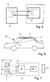
In Figur 6 ist ein Fahrzeug 12 gezeigt, bei dem im Dachbereich und an
der D-Säule jeweils ein Deformationselement 1l und 1ll schematisch
dargestellt sind. Weitere Deformationselemente können vorgesehen
sein. Die Deformationselemente 1l und 1II sind in die
Fahrzeugkonstruktion eingebaut. Im Bereich des Lenkrades ist eine
Leseeinheit 9 vorgesehen, die in der dargestellten Ausführungsform fest
mit dem Fahrzeug verbunden ist, d.h. stationär ist. In Figur 7 ist die
Funktionsweise des in Figur 6 dargestellten Dokumentationssystems
schematisch gezeigt. Von den Identifikationselementen 2l und 2ll, die in
den Deformationselementen 1l und 1II vorgesehen sind, werden Daten
mittels Antennen 7l und 7ll an die Antenne 8 der Leseeinheit 9
übertragen. Diese Leseeinheit 9 ist Teil der zentralen Einheit 14 des
Dokumentationssystems. Weitere Bestandteile der zentralen Einheit 14
können Bearbeitungseinheiten sein, in denen die Daten z.B. zu
optischen Signalen verarbeitet werden, oder mit anderen Werten
verglichen werden. In der dargestellten Ausführungsform ist die zentrale
Einheit 14 mit einer Wegfahrsperre 13 verbunden. Die von den
Deformationselementen 1l, 1ll, etc. empfangenen Daten werden hierbei
in der zentralen Einheit 14 mit Soll-Daten verglichen. Stimmt eines der
empfangenen Merkmale nicht mit dem vorgegebenen Merkmal überein,
so wird die Wegfahrsperre 13 aktiviert und das Fahrzeug kann nicht
bewegt werden. Durch ein solches Dokumentationssystem kann
insbesondere sichergestellt werden, dass nach Reparaturarbeiten wieder
alle Deformationselemente 1 in der richtigen Position eingebaut wurden.
Wird die zentrale Einheit 14 als mobile Einheit gestaltet, so kann das
Dokumentationssystem ideal für die Überwachung der Montage von
Fahrzeugen verwendet werden. Dabei kann die zentrale Einheit 14 in die
Nähe der Deformationselemente 1l, 1ll, etc. gebracht werden und so
deren Präsenz und korrekter Einbau überprüft werden.In Figure 6, a
Claims (7)
Applications Claiming Priority (2)
| Application Number | Priority Date | Filing Date | Title |
|---|---|---|---|
| DE10048288 | 2000-09-29 | ||
| DE10048288A DE10048288C1 (en) | 2000-09-29 | 2000-09-29 | Energy-absorbing deformation element for automobile has incorporated passive inductive identification element with read-only function |
Publications (2)
| Publication Number | Publication Date |
|---|---|
| EP1193130A2 true EP1193130A2 (en) | 2002-04-03 |
| EP1193130A3 EP1193130A3 (en) | 2004-04-21 |
Family
ID=7658097
Family Applications (1)
| Application Number | Title | Priority Date | Filing Date |
|---|---|---|---|
| EP01120927A Withdrawn EP1193130A3 (en) | 2000-09-29 | 2001-08-31 | Deformable element and documentation system for deformable elements for use in a vehicle |
Country Status (3)
| Country | Link |
|---|---|
| US (1) | US6710712B2 (en) |
| EP (1) | EP1193130A3 (en) |
| DE (1) | DE10048288C1 (en) |
Families Citing this family (1)
| Publication number | Priority date | Publication date | Assignee | Title |
|---|---|---|---|---|
| DE102015106450A1 (en) * | 2015-04-27 | 2016-10-27 | Webasto SE | Arrangement for a vehicle roof |
Family Cites Families (11)
| Publication number | Priority date | Publication date | Assignee | Title |
|---|---|---|---|---|
| US4581524A (en) * | 1983-04-26 | 1986-04-08 | Minnesota Mining And Manufacturing Company | Flexible ferromagnetic marker for the detection of objects having markers secured thereto |
| DE4335308C2 (en) * | 1993-10-16 | 1995-12-14 | Daimler Benz Ag | Identification of vehicles to make theft and / or unauthorized sale more difficult |
| DE4340346A1 (en) * | 1993-11-26 | 1995-06-01 | Audi Ag | Application of plastics foam for vehicle filter |
| JP2697606B2 (en) * | 1994-05-10 | 1998-01-14 | 日産自動車株式会社 | Vehicle antitheft device |
| US5963132A (en) * | 1996-10-11 | 1999-10-05 | Avid Indentification Systems, Inc. | Encapsulated implantable transponder |
| US6464249B1 (en) * | 1997-05-15 | 2002-10-15 | Donald R. Lacroix | Selectively buffered dual stage air bag assembly, and method of using same |
| DE19830024A1 (en) * | 1998-07-04 | 2000-01-05 | Mannesmann Vdo Ag | Identification element for a vehicle |
| DE19831118A1 (en) * | 1998-07-11 | 2000-01-13 | Brueckle Christian | Automobile identification for theft prevention |
| US6031459A (en) * | 1998-07-22 | 2000-02-29 | Micron Technology, Inc. | Wireless communication devices, radio frequency identification devices, and methods of forming wireless communication devices and radio frequency identification devices |
| ES2333897T3 (en) * | 1998-08-14 | 2010-03-02 | 3M Innovative Properties Company | METHOD TO INTERROGATE A CONTAINER CARRYING AN RFID LABEL. |
| US6121880A (en) * | 1999-05-27 | 2000-09-19 | Intermec Ip Corp. | Sticker transponder for use on glass surface |
-
2000
- 2000-09-29 DE DE10048288A patent/DE10048288C1/en not_active Expired - Fee Related
-
2001
- 2001-08-31 EP EP01120927A patent/EP1193130A3/en not_active Withdrawn
- 2001-09-06 US US09/948,030 patent/US6710712B2/en not_active Expired - Lifetime
Non-Patent Citations (1)
| Title |
|---|
| None |
Also Published As
| Publication number | Publication date |
|---|---|
| US6710712B2 (en) | 2004-03-23 |
| EP1193130A3 (en) | 2004-04-21 |
| DE10048288C1 (en) | 2001-12-06 |
| US20020043794A1 (en) | 2002-04-18 |
Similar Documents
| Publication | Publication Date | Title |
|---|---|---|
| DE102017009055B4 (en) | Arrangement of a sensor-active surface having sensor on an external attachment of a vehicle | |
| EP1390238B1 (en) | Shock-absorbent lining element for the interior of a vehicle | |
| DE102006041588B4 (en) | Method for producing a motor vehicle | |
| EP1867559A2 (en) | Reinforcement piece for crash protection | |
| DE102007034313A1 (en) | Energy absorber for use as impact protection in a motor vehicle | |
| DE60317364T2 (en) | DEVICE FOR STARTER CONTROL OF AN AIRBAGING DEVICE | |
| EP1035283A2 (en) | Electronic security arrangement with range determination of an authentication element, especially vehicle locking system | |
| DE10048288C1 (en) | Energy-absorbing deformation element for automobile has incorporated passive inductive identification element with read-only function | |
| DE102017011968A1 (en) | Device for protecting battery modules in a motor vehicle | |
| EP1362771B1 (en) | Composite car body part | |
| DE102019115420B4 (en) | ENERGY ABSORBING Tread | |
| DE102014203512A1 (en) | Bumper unit for a motor vehicle | |
| DE102014208780A1 (en) | Method for monitoring a loading state and a loading or unloading process of a motor vehicle | |
| DE10026382B4 (en) | Method and device for setting user-specific settings in motor vehicles | |
| WO2020200604A1 (en) | Energy absorption device | |
| DE102018126219A1 (en) | Calculation means, arrangement and method for determining the position of an authentication means for a vehicle | |
| DE20321718U1 (en) | Access control for motor vehicles | |
| DE102009044707A1 (en) | Collision detecting device for vehicle, has vehicle bumper and chamber component, which is made of soft synthetic resin | |
| DE102007032030A1 (en) | Motor vehicle e.g. car, front end, has lower leg rest with deformation profile part, which extends over total width of vehicle and held at support structure of vehicle in rearward manner | |
| DE102020116559B4 (en) | Tail assembly | |
| DE102006059670A1 (en) | Rear bumpers for motor vehicle, particularly passenger car, has outer lining between two offset end sections and central section with loading edge, which has reduced height against end sections in mounted condition of rear bumper | |
| DE2620732B1 (en) | Method for coordinating individual parts of variable production units, in particular body parts during assembly in cycles | |
| DE3634559C1 (en) | Instrument panel for vehicles, especially passenger motor cars | |
| DE19604213A1 (en) | Impact absorbing equipment with chambered element, for use on vehicle | |
| WO2004052669A1 (en) | Protective cover for motor vehicles |
Legal Events
| Date | Code | Title | Description |
|---|---|---|---|
| PUAI | Public reference made under article 153(3) epc to a published international application that has entered the european phase |
Free format text: ORIGINAL CODE: 0009012 |
|
| AK | Designated contracting states |
Kind code of ref document: A2 Designated state(s): AT BE CH CY DE DK ES FI FR GB GR IE IT LI LU MC NL PT SE TR |
|
| AX | Request for extension of the european patent |
Free format text: AL;LT;LV;MK;RO;SI |
|
| PUAL | Search report despatched |
Free format text: ORIGINAL CODE: 0009013 |
|
| AK | Designated contracting states |
Kind code of ref document: A3 Designated state(s): AT BE CH CY DE DK ES FI FR GB GR IE IT LI LU MC NL PT SE TR |
|
| AX | Request for extension of the european patent |
Extension state: AL LT LV MK RO SI |
|
| RIC1 | Information provided on ipc code assigned before grant |
Ipc: 7B 60R 25/00 B Ipc: 7B 60R 13/10 B Ipc: 7B 60R 13/02 A |
|
| 17P | Request for examination filed |
Effective date: 20040414 |
|
| 17Q | First examination report despatched |
Effective date: 20041118 |
|
| AKX | Designation fees paid |
Designated state(s): DE FR GB IT |
|
| STAA | Information on the status of an ep patent application or granted ep patent |
Free format text: STATUS: THE APPLICATION HAS BEEN WITHDRAWN |
|
| 18W | Application withdrawn |
Effective date: 20080709 |