EP1193059A1 - Dispositif pour régler l'élargissement latéral d'une bande - Google Patents
Dispositif pour régler l'élargissement latéral d'une bande Download PDFInfo
- Publication number
- EP1193059A1 EP1193059A1 EP01121641A EP01121641A EP1193059A1 EP 1193059 A1 EP1193059 A1 EP 1193059A1 EP 01121641 A EP01121641 A EP 01121641A EP 01121641 A EP01121641 A EP 01121641A EP 1193059 A1 EP1193059 A1 EP 1193059A1
- Authority
- EP
- European Patent Office
- Prior art keywords
- fan
- web
- printing
- sleeve
- plate cylinder
- Prior art date
- Legal status (The legal status is an assumption and is not a legal conclusion. Google has not performed a legal analysis and makes no representation as to the accuracy of the status listed.)
- Granted
Links
Images


Classifications
-
- B—PERFORMING OPERATIONS; TRANSPORTING
- B41—PRINTING; LINING MACHINES; TYPEWRITERS; STAMPS
- B41F—PRINTING MACHINES OR PRESSES
- B41F13/00—Common details of rotary presses or machines
- B41F13/08—Cylinders
- B41F13/10—Forme cylinders
- B41F13/12—Registering devices
- B41F13/16—Registering devices with means for displacing the printing formes on the cylinders
-
- B—PERFORMING OPERATIONS; TRANSPORTING
- B41—PRINTING; LINING MACHINES; TYPEWRITERS; STAMPS
- B41P—INDEXING SCHEME RELATING TO PRINTING, LINING MACHINES, TYPEWRITERS, AND TO STAMPS
- B41P2227/00—Mounting or handling printing plates; Forming printing surfaces in situ
- B41P2227/10—Attaching several printing plates on one cylinder
- B41P2227/11—Attaching several printing plates on one cylinder in axial direction
Definitions
- the present invention relates to a method and an apparatus for minimizing the effects of the fan-out effect of the web in a web-fed rotary printing press according to the preamble of claims 1, 8 and 12.
- a web-fed rotary offset press typically prints four colors on one Web of material such as paper. While the web rubber blanket cylinder If it passes through printing units, it becomes damp, which can cause the web to stretch.
- the second printing unit must Print images or the print on the web correctly registered, i.e. be aligned, thus, for example, registering a second color as desired on a printed image is applied that has already been printed by the first printing unit.
- So-called multi-plate plate cylinders are used for some printing applications which can be applied a plurality of axially spaced-apart pressure plates. to Correct alignment of each printing plate allows the plates to be used independently be movable.
- US 4,207,815 discloses a two-plate plate cylinder.
- a plate lies against one Large diameter section and another plate is on a rotatable and sleeve axially movable with respect to the large diameter portion.
- the sleeve is attached to a stepped shaft.
- For setting the axial and circumferential register of the Helical teeth are provided for the plates.
- This arrangement requires one complicated plate cylinder with double diameter and a complicated Gearing and can only be used with a two-platen configuration.
- the device described in the mentioned document also has the disadvantage that there are no sensors to sense the different sections of the web, e.g. the front and back of the web.
- the device also has the disadvantage of that a complex helical gear mechanism the circumferential and lateral adjustment controls the sleeve and therefore the device becomes more difficult and time consuming repair and maintenance.
- US 5,383,393 discloses a multi-color web-fed rotary offset printing machine which a plurality of printing sections arranged along a running line of a paper web, a variety of register adjustment devices, a paper chuck and includes a variety of width adjustment devices.
- Each of the print sections further comprises at least one divided plate cylinder, each divided Section of the same moves independently in the axial direction and / or in the circumferential direction becomes.
- the document also discloses one with each of the divided Plate cylinders mechanically connected in the printing sections Register setting device.
- the disclosed device further includes one Adjustment mechanism for moving the divided sections in response to the a sensor for detecting that of each of the printing sections on the paper web printed lines and pictures connected control unit.
- the device described in US 5,383,393 has the disadvantage that it is not there are several sensors for scanning the web at different points, which is why one Determination of the fan-out is omitted. Furthermore, the device does not have a third sleeve, thus the ability to adapt to different fan-out widths of the web is limited. The device also has the disadvantage that to compensate for the fan-out the width of the web and not the displacement of the printing plates is changed. The Changing the width of the web may result in the procedure not being for everyone Paper types work equally well. Furthermore, the device for approximation appears Web width complicated.
- Another object of the invention is a web-fed rotary printing press to provide, which has a reduced fan-out effect.
- a printing cylinder comprises at least one output signal generating fan-out sensor for scanning a web, a first rotatable section with a medium printed or printed image area on the surface, and a first and a second end, a first sleeve which extends around the circumference of the first end and a second sleeve which extends around the circumference of the second end is arranged, the first and second sleeve on their surfaces pressure surfaces or Have printed image areas and with respect to the average printing area depending on determined fan-out signal of the sensor can be moved in such a way that that of the sensor certain value for the respective fan-out or the deviation of the certain value of a given value is minimal.
- first and second sleeve axially with respect to the average pressure surface of the Present invention are movable, more precise adjustments of the printing surface to minimize printing errors caused by wider printing, the fan-out effect of the web.
- One printing plate can be placed on the middle printing surface and on the two on the side adjacent sleeves can be applied to two printing plates.
- the first and second sleeves can move axially from the medium pressure area away or moved towards this. Although this movement If the problems caused by fan-out are not completely corrected, she can However, significantly reduce the effects of fan-out, especially e.g. B. if the device according to the invention is used in newspapers in which a variety is arranged from newspaper pages across the width of the web.
- Two fan-out sensors are preferably provided on one side of the web.
- the Sensors are preferably near the edges of the web, but can also arranged in an unprinted area, preferably near the center of the sleeve his.
- At least one register sensor is preferably the correct one Overall register setting provided.
- two in register sensors located in the middle of the web are used, preferably a first register sensor on a first side of the web and a second register sensor a second side of the web is arranged.
- the middle printing area and the first and second sleeves can be lasered be writable.
- Laser-writable sleeves offer the advantage that a desired Printed image can be changed without mechanically removing a section of the sleeve or must be waited for the deletion and rewriting of the printed image, and therefore machine downtime can be reduced.
- the middle pressure surface and the first and second sleeves can also each have one Include gap or a channel for inserting a pressure plate.
- Providing one Spalts has the advantage of making a change to the desired print image can be removed by first removing the existing pressure plate and then the existing one Plate can be changed and reinserted or a plate with a different print image is added, especially for the so-called Imprint operation is of great advantage.
- a printing press comprises at least a first sensor for Scanning register marks, at least one second sensor for determining the fan-out and a rotatable cylinder having an axially with respect to a second portion adjustable first section.
- the extent of the fan-out can be determined automatically with the first and second sensors and can adjust the effects of the fan-out by adjusting the first and axial second section can be compensated.
- the adjustment offers the advantage of one more efficient printing.
- the first sensor or sensors preferably detect through the middle one Image area printed register marks and the second sensor detects through the sleeves Fan-out stamps printed on the web.
- the second sensor or sensors can be photocell detectors or video detectors include.
- the photocell or video detectors allow a comparison of the situation a printed image with the position of a previously printed further printed image. To this Way, the extent of the fan-out can be done without using brands on the web be determined. However, the use of fan-out brands on the web like for example registration marks, preferred.
- a method for correcting the fan-out in a web-fed rotary printing press comprises the following steps: Scanning register marks for the entire circumferential and / or side register setting of a printing cylinder; Scanning a portion of the web that contains no register marks to provide fan-out information, and changing a lateral position of a first part of the printing cylinder with respect to a second part of the printing cylinder depending on the fan-out information so that the fan -Out the web is minimized.
- the first part of the impression cylinder is a sleeve and the second part of the Printing cylinder an image surface of a cylinder carrying a printed image, the sleeve can be moved axially to minimize the fan-out effect.
- the sleeves can be made in a manner similar to that in U.S. Patent Application No. 09 / 627,639 described manner can be moved.
- Fig. 1 shows a simplified schematic view of a printing cylinder 1 with a middle printed image area 2, a first end 4 and a second end 6.
- a first Sleeve 8 is arranged around the circumference of the first end 4, and a second sleeve 10 is arranged around the circumference of the second end 6.
- the first sleeve 8 and the second sleeves 10 are non-rotatably attached to the first end 4 and the second end 6, for example by flanges 14.
- the first sleeve 8 and the second sleeve 10 are both axially displaceable with respect to the middle printed image area 2.
- Embodiment is located in a radially lower recess of the end 4th rotatable and axially displaceable arm 15 in an axially fixed, but rotatably decoupled with respect to a gear 19 by a bearing, not shown Position, wherein the gear 19 normally with a drive shaft 21 of the Cylinder 2 rotates.
- the gear wheel 19 is threaded on the drive shaft 21 held in such a way that there is a rotation between gear 19 and Drive shaft 21 moves axially with respect to cylinder 2 and drive shaft 21 when a fan-out register setting device 17 for the first sleeve 8 is actuated.
- the Gear 19 is engaged on an outer portion with a gear 27, which is connected by a coupling 25 to a servomotor 23 of the device 17.
- a gear 27 is connected by a coupling 25 to a servomotor 23 of the device 17.
- the clutch 25 is engaged or closed and the motor 23 rotates the gear 27 to the gear 19 with respect to To move shaft 21 axially.
- This movement pulls or pushes the flange 14, and thereby the sleeve 8, axially with respect to the middle printed image section 2.
- the coupling 25 is then disengaged so that the gear 19 and the shaft 21 e.g. by virtue of of friction turn back together.
- a further clutch can be provided be to either lock the gear 19 and shaft 21 together or rotatably to couple with each other.
- An overall register actuator 29 can preferably move the entire cylinder 2 axially and in Move circumferentially in a conventional manner. If the overall register is set, the clutch 25 is disengaged and the gear 27 is axially related of the gear 19 slidably.
- the second sleeve 10 can be a device similar to the fan-out register setting device 17 have.
- first sleeve 8 and the second sleeve 10 can be moved axially by flanges as described in U.S. Patent Application No. 09 / 627,639.
- the rotation of the printing cylinder 2 makes the first sleeve 8 and the second sleeve 10 by the flanges 14 or by other supporting devices, which also include the first sleeve 8 and stabilize the second sleeve 10 with respect to the impression cylinder 2, rotated.
- the first Sleeve 8 and second sleeve 10 each comprise a plurality of gaps or channels 16 for inserting plates so that pre-imaged plates can be attached.
- the first sleeve 8 and the second sleeve 10 could also be directly laser-writable or be coated with a laser-writable material.
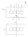
- Fig. 2 and Fig. 3 show a printing unit 60 of an offset printing press, which in the same Has a first printing unit 58.
- the printing unit 60 comprises a first one Printing cylinder 20 and a second printing cylinder 22, each similar to that in Fig. 1st described pressure cylinder 1 are formed.
- a print image is made from the first Transfer cylinder 20 to a first blanket cylinder 24 to a first surface 41 to print a web 28.
- Another print image is from the second Transfer cylinder 22 to a second blanket cylinder 26 to a second Surface 42 of the web 28 to be printed.
- a large number of first sensors 30 monitor this Axial and circumferential register for the web 28 by scanning marks on the web 28.
- a plurality of second sensors 32 scans additional brands, the conclusions on the Enable fan-out of the web 28 at the edge areas 43 and 44 of the web.
- the data obtained from the first sensors 30 and the second sensors 32 become axial Moving a first sleeve 34, a second sleeve 36, a third sleeve 38 and one fourth sleeve 40 is used to adjust the printing area by the fan-out of the To minimize web 28 caused printing errors.
- the sensors 32 provide information regarding the by the first printing unit 58 caused fan-out. If the fan-out register marks due to fan-out, sleeves 38, 40 and 34, 36 by respective fan-out register setting devices with respect to the middle ones Print image areas are moved outwards to minimize the fan-out. If the For example, fan-out marks have shifted by 1 mm 0.5 mm outwards.
- the sensors 32 can be automatic Provide feedback to a controller that controls the fan-out register setting devices 17 controls.
Landscapes
- Engineering & Computer Science (AREA)
- Mechanical Engineering (AREA)
- Inking, Control Or Cleaning Of Printing Machines (AREA)
- Folding Of Thin Sheet-Like Materials, Special Discharging Devices, And Others (AREA)
- Photosensitive Polymer And Photoresist Processing (AREA)
Applications Claiming Priority (2)
| Application Number | Priority Date | Filing Date | Title |
|---|---|---|---|
| US675494 | 2000-09-29 | ||
| US09/675,494 US6553908B1 (en) | 2000-09-29 | 2000-09-29 | Web fanout control system |
Publications (2)
| Publication Number | Publication Date |
|---|---|
| EP1193059A1 true EP1193059A1 (fr) | 2002-04-03 |
| EP1193059B1 EP1193059B1 (fr) | 2006-06-14 |
Family
ID=24710742
Family Applications (1)
| Application Number | Title | Priority Date | Filing Date |
|---|---|---|---|
| EP01121641A Expired - Lifetime EP1193059B1 (fr) | 2000-09-29 | 2001-09-13 | Dispositif pour régler l'élargissement latéral d'une bande |
Country Status (5)
| Country | Link |
|---|---|
| US (1) | US6553908B1 (fr) |
| EP (1) | EP1193059B1 (fr) |
| JP (1) | JP2002160346A (fr) |
| AT (1) | ATE329758T1 (fr) |
| DE (2) | DE10145016A1 (fr) |
Cited By (3)
| Publication number | Priority date | Publication date | Assignee | Title |
|---|---|---|---|---|
| US6796233B2 (en) | 2002-11-20 | 2004-09-28 | Heidelberger Druckmaschinen Ag | Plate cylinder with splined shell |
| US7320282B2 (en) | 2002-08-12 | 2008-01-22 | Koenig & Bauer Aktiengesellschaft | Cylinders of a web-fed printing press with axially displaceable holding device |
| DE202016102779U1 (de) * | 2016-05-25 | 2017-08-28 | Bobst Bielefeld Gmbh | Vorrichtung zur Betätigung einer hydraulischen Trägerstange einer Rotationsdruckmaschine |
Families Citing this family (13)
| Publication number | Priority date | Publication date | Assignee | Title |
|---|---|---|---|---|
| US6868783B2 (en) * | 2001-09-07 | 2005-03-22 | Goss International Americas, Inc. | Printing press with multiple-image-carrying cylinder |
| US6851362B2 (en) * | 2002-03-22 | 2005-02-08 | Goss International Americas, Inc. | Printing cylinder with fanout compensation |
| DE10225199B4 (de) * | 2002-06-06 | 2004-05-06 | Maschinenfabrik Wifag | Fluidbeaufschlagter FanOut-Kompensator |
| DE10352619B4 (de) * | 2003-07-11 | 2012-09-27 | Koenig & Bauer Aktiengesellschaft | Verfahren und Vorrichtung zur Beeinflussung des Fan-Out-Effektes |
| DE10340569A1 (de) * | 2003-09-01 | 2005-04-07 | Koenig & Bauer Ag | Verfahren zur Reduktion von Passerfehlern auf einer in einer bahnverarbeitenden Vorrichtung und ein Druckwerk |
| WO2006104830A2 (fr) | 2005-03-30 | 2006-10-05 | Goss International Americas, Inc. | Presse a imprimer offset sur papier sans fin pourvue d'une lame plieuse articulee |
| WO2006104828A2 (fr) | 2005-03-30 | 2006-10-05 | Goss International Americas, Inc. | Mecanisme elevateur de cylindre porte-blanchet en porte-a-faux |
| EP2441584B1 (fr) * | 2005-03-30 | 2014-04-30 | Goss International Americas, Inc. | Presse rotative d'ompression offset avec calage automatique |
| CN101495313B (zh) * | 2005-03-30 | 2011-11-09 | 高斯国际美洲公司 | 具有胶印滚筒脱开支撑表面的印刷单元 |
| US8037818B2 (en) * | 2005-04-11 | 2011-10-18 | Goss International Americas, Inc. | Print unit with single motor drive permitting autoplating |
| US8733249B2 (en) * | 2007-02-20 | 2014-05-27 | Goss International Americas, Inc. | Real-time print product status |
| US20110155006A1 (en) * | 2009-12-31 | 2011-06-30 | Bryce Corporation | Interlocking printing sleeves |
| JP6934707B2 (ja) * | 2016-07-13 | 2021-09-15 | グローリー株式会社 | 有価証券の文字/番号検査装置及び文字/番号検査方法 |
Citations (2)
| Publication number | Priority date | Publication date | Assignee | Title |
|---|---|---|---|---|
| US4207815A (en) * | 1977-04-27 | 1980-06-17 | Kabushiki Kaisha Tokyo Kikai Seisakusho | Rotary press with means for adjusting the positions of printing plates on plate cylinders |
| US5383393A (en) * | 1992-07-29 | 1995-01-24 | Kabushikigaisha Tokyo Kikai Seisakusho | Multicolor lithographic rotary press |
Family Cites Families (5)
| Publication number | Priority date | Publication date | Assignee | Title |
|---|---|---|---|---|
| GB8729197D0 (en) | 1987-12-15 | 1988-01-27 | Ciba Geigy Ag | Preparation of polymeric colour couplers |
| JP2602488B2 (ja) * | 1989-05-30 | 1997-04-23 | 株式会社 東京機械製作所 | 両面多色印刷機 |
| JP2726716B2 (ja) | 1989-10-26 | 1998-03-11 | 三菱重工業株式会社 | 輪転印刷機の分割版胴 |
| US5365847A (en) | 1993-09-22 | 1994-11-22 | Rockwell International Corporation | Control system for a printing press |
| DE29718968U1 (de) * | 1996-10-25 | 1997-12-18 | Koenig & Bauer Albert Ag | Anordnung zur Korrektur des Fan-Out-Effektes an Rollenrotationsdruckmaschinen |
-
2000
- 2000-09-29 US US09/675,494 patent/US6553908B1/en not_active Expired - Fee Related
-
2001
- 2001-09-13 AT AT01121641T patent/ATE329758T1/de not_active IP Right Cessation
- 2001-09-13 DE DE10145016A patent/DE10145016A1/de not_active Withdrawn
- 2001-09-13 EP EP01121641A patent/EP1193059B1/fr not_active Expired - Lifetime
- 2001-09-13 DE DE50110129T patent/DE50110129D1/de not_active Expired - Lifetime
- 2001-09-27 JP JP2001297569A patent/JP2002160346A/ja active Pending
Patent Citations (2)
| Publication number | Priority date | Publication date | Assignee | Title |
|---|---|---|---|---|
| US4207815A (en) * | 1977-04-27 | 1980-06-17 | Kabushiki Kaisha Tokyo Kikai Seisakusho | Rotary press with means for adjusting the positions of printing plates on plate cylinders |
| US5383393A (en) * | 1992-07-29 | 1995-01-24 | Kabushikigaisha Tokyo Kikai Seisakusho | Multicolor lithographic rotary press |
Cited By (4)
| Publication number | Priority date | Publication date | Assignee | Title |
|---|---|---|---|---|
| US7320282B2 (en) | 2002-08-12 | 2008-01-22 | Koenig & Bauer Aktiengesellschaft | Cylinders of a web-fed printing press with axially displaceable holding device |
| US6796233B2 (en) | 2002-11-20 | 2004-09-28 | Heidelberger Druckmaschinen Ag | Plate cylinder with splined shell |
| DE202016102779U1 (de) * | 2016-05-25 | 2017-08-28 | Bobst Bielefeld Gmbh | Vorrichtung zur Betätigung einer hydraulischen Trägerstange einer Rotationsdruckmaschine |
| US11001052B2 (en) | 2016-05-25 | 2021-05-11 | Bobst Bielefeld Gmbh | Apparatus for actuating a hydraulic carrier rod of a rotary printing machine |
Also Published As
| Publication number | Publication date |
|---|---|
| DE50110129D1 (de) | 2006-07-27 |
| DE10145016A1 (de) | 2002-07-25 |
| US6553908B1 (en) | 2003-04-29 |
| EP1193059B1 (fr) | 2006-06-14 |
| ATE329758T1 (de) | 2006-07-15 |
| JP2002160346A (ja) | 2002-06-04 |
Similar Documents
| Publication | Publication Date | Title |
|---|---|---|
| EP1193059B1 (fr) | Dispositif pour régler l'élargissement latéral d'une bande | |
| EP1666252B1 (fr) | Dispositif et procédé de réglage de l'image d'impression dans une machine d'impression flexographique | |
| EP0782919B1 (fr) | Unité d'impression pour une presse rotative pour bandes | |
| CH667425A5 (de) | Rotationsdruckerpresse, insbesondere fuer mehrfarbendruck. | |
| EP0806294B1 (fr) | Procédé et dispositif pour le réglage du registre circonférentiel dans une presse rotative comprenant un cylindre porte-cliché muni d'un manchon porte-cliché | |
| EP1291175B1 (fr) | Cylindre porte-plaque pour plusieurs images | |
| EP2014470B1 (fr) | Procédé destiné à la régulation automatique du repérage entre les impressions dans une presse rotative multicolore | |
| WO2006081950A1 (fr) | Procede de reperage | |
| EP0895857B1 (fr) | Dispositif et procédé pour changer l'image d'impression pendant l'opération d'une machine d'impression | |
| EP1176008B1 (fr) | Machine d'impression à plusieurs couleurs avec un cylindre de blanchet commun | |
| EP1050404B1 (fr) | Presse offset pour imprimer deux bandes | |
| EP0606861B1 (fr) | Dispositif d'encrage pour une machine à imprimer rotative | |
| DE3112775C2 (de) | Rotationsdruckmaschine in Reihenbauweise | |
| EP0534160B1 (fr) | Machine à imprimer rotative | |
| EP0995596B1 (fr) | Dispositif et procédé pour la mise en oeuvre d'un changement de plaques en marche | |
| DE4410132C2 (de) | Flexodruckmaschine, insbesondere für Mehrfarbendruck | |
| EP1457334A1 (fr) | Procédé et dispositif pour régler le registre dans une machine à imprimer | |
| EP1005981B1 (fr) | Dispositif et méthode pour la compensation de la glissade d'un cliché d' impression tubulaire | |
| EP0726146B1 (fr) | Dispositif de commande pour une machine à imprimer | |
| DE4426992A1 (de) | Verfahren und Vorrichtung zur Zustandsüberwachung einer umstellbaren Bogendruckmaschine | |
| EP1156382B1 (fr) | Méthode et appareil pour l'ajustement de registre dans une imprimante couleur | |
| DE3115141A1 (de) | Vorrichtung zum diagonalverstellen eines zylinders einer druckmaschine, vorzugsweise des plattenzylinders einer bogenrotations-offsetdruckmaschine | |
| EP1264691A1 (fr) | Groupe d'impression | |
| EP1132204A1 (fr) | Unité d'impression pour l'impression offset | |
| DE3633997C2 (fr) |
Legal Events
| Date | Code | Title | Description |
|---|---|---|---|
| PUAI | Public reference made under article 153(3) epc to a published international application that has entered the european phase |
Free format text: ORIGINAL CODE: 0009012 |
|
| AK | Designated contracting states |
Kind code of ref document: A1 Designated state(s): AT BE CH CY DE DK ES FI FR GB GR IE IT LI LU MC NL PT SE TR |
|
| AX | Request for extension of the european patent |
Free format text: AL;LT;LV;MK;RO;SI |
|
| 17P | Request for examination filed |
Effective date: 20020128 |
|
| AKX | Designation fees paid |
Free format text: AT BE CH CY DE DK ES FI FR GB GR IE IT LI LU MC NL PT SE TR |
|
| RAP1 | Party data changed (applicant data changed or rights of an application transferred) |
Owner name: GOSS INTERNATIONAL AMERICAS, INC. |
|
| GRAP | Despatch of communication of intention to grant a patent |
Free format text: ORIGINAL CODE: EPIDOSNIGR1 |
|
| GRAS | Grant fee paid |
Free format text: ORIGINAL CODE: EPIDOSNIGR3 |
|
| GRAA | (expected) grant |
Free format text: ORIGINAL CODE: 0009210 |
|
| AK | Designated contracting states |
Kind code of ref document: B1 Designated state(s): AT BE CH CY DE DK ES FI FR GB GR IE IT LI LU MC NL PT SE TR |
|
| PG25 | Lapsed in a contracting state [announced via postgrant information from national office to epo] |
Ref country code: NL Free format text: LAPSE BECAUSE OF FAILURE TO SUBMIT A TRANSLATION OF THE DESCRIPTION OR TO PAY THE FEE WITHIN THE PRESCRIBED TIME-LIMIT Effective date: 20060614 Ref country code: GB Free format text: LAPSE BECAUSE OF FAILURE TO SUBMIT A TRANSLATION OF THE DESCRIPTION OR TO PAY THE FEE WITHIN THE PRESCRIBED TIME-LIMIT Effective date: 20060614 Ref country code: IE Free format text: LAPSE BECAUSE OF FAILURE TO SUBMIT A TRANSLATION OF THE DESCRIPTION OR TO PAY THE FEE WITHIN THE PRESCRIBED TIME-LIMIT Effective date: 20060614 Ref country code: FI Free format text: LAPSE BECAUSE OF FAILURE TO SUBMIT A TRANSLATION OF THE DESCRIPTION OR TO PAY THE FEE WITHIN THE PRESCRIBED TIME-LIMIT Effective date: 20060614 Ref country code: IT Free format text: LAPSE BECAUSE OF FAILURE TO SUBMIT A TRANSLATION OF THE DESCRIPTION OR TO PAY THE FEE WITHIN THE PRESCRIBED TIME-LIMIT;WARNING: LAPSES OF ITALIAN PATENTS WITH EFFECTIVE DATE BEFORE 2007 MAY HAVE OCCURRED AT ANY TIME BEFORE 2007. THE CORRECT EFFECTIVE DATE MAY BE DIFFERENT FROM THE ONE RECORDED. Effective date: 20060614 |
|
| REG | Reference to a national code |
Ref country code: GB Ref legal event code: FG4D Free format text: NOT ENGLISH |
|
| REG | Reference to a national code |
Ref country code: CH Ref legal event code: EP |
|
| REG | Reference to a national code |
Ref country code: CH Ref legal event code: NV Representative=s name: KIRKER & CIE SA |
|
| REG | Reference to a national code |
Ref country code: IE Ref legal event code: FG4D Free format text: LANGUAGE OF EP DOCUMENT: GERMAN |
|
| REF | Corresponds to: |
Ref document number: 50110129 Country of ref document: DE Date of ref document: 20060727 Kind code of ref document: P |
|
| PG25 | Lapsed in a contracting state [announced via postgrant information from national office to epo] |
Ref country code: DK Free format text: LAPSE BECAUSE OF FAILURE TO SUBMIT A TRANSLATION OF THE DESCRIPTION OR TO PAY THE FEE WITHIN THE PRESCRIBED TIME-LIMIT Effective date: 20060914 Ref country code: SE Free format text: LAPSE BECAUSE OF FAILURE TO SUBMIT A TRANSLATION OF THE DESCRIPTION OR TO PAY THE FEE WITHIN THE PRESCRIBED TIME-LIMIT Effective date: 20060914 |
|
| PGFP | Annual fee paid to national office [announced via postgrant information from national office to epo] |
Ref country code: FR Payment date: 20060918 Year of fee payment: 6 |
|
| PG25 | Lapsed in a contracting state [announced via postgrant information from national office to epo] |
Ref country code: ES Free format text: LAPSE BECAUSE OF FAILURE TO SUBMIT A TRANSLATION OF THE DESCRIPTION OR TO PAY THE FEE WITHIN THE PRESCRIBED TIME-LIMIT Effective date: 20060925 |
|
| PGFP | Annual fee paid to national office [announced via postgrant information from national office to epo] |
Ref country code: GB Payment date: 20060925 Year of fee payment: 6 |
|
| PG25 | Lapsed in a contracting state [announced via postgrant information from national office to epo] |
Ref country code: MC Free format text: LAPSE BECAUSE OF NON-PAYMENT OF DUE FEES Effective date: 20060930 Ref country code: BE Free format text: LAPSE BECAUSE OF NON-PAYMENT OF DUE FEES Effective date: 20060930 |
|
| PG25 | Lapsed in a contracting state [announced via postgrant information from national office to epo] |
Ref country code: PT Free format text: LAPSE BECAUSE OF FAILURE TO SUBMIT A TRANSLATION OF THE DESCRIPTION OR TO PAY THE FEE WITHIN THE PRESCRIBED TIME-LIMIT Effective date: 20061114 |
|
| NLV1 | Nl: lapsed or annulled due to failure to fulfill the requirements of art. 29p and 29m of the patents act | ||
| GBV | Gb: ep patent (uk) treated as always having been void in accordance with gb section 77(7)/1977 [no translation filed] |
Effective date: 20060614 |
|
| REG | Reference to a national code |
Ref country code: IE Ref legal event code: FD4D |
|
| PLBE | No opposition filed within time limit |
Free format text: ORIGINAL CODE: 0009261 |
|
| STAA | Information on the status of an ep patent application or granted ep patent |
Free format text: STATUS: NO OPPOSITION FILED WITHIN TIME LIMIT |
|
| EN | Fr: translation not filed | ||
| 26N | No opposition filed |
Effective date: 20070315 |
|
| PG25 | Lapsed in a contracting state [announced via postgrant information from national office to epo] |
Ref country code: AT Free format text: LAPSE BECAUSE OF NON-PAYMENT OF DUE FEES Effective date: 20060913 |
|
| BERE | Be: lapsed |
Owner name: GOSS INTERNATIONAL AMERICAS, INC. Effective date: 20060930 |
|
| PG25 | Lapsed in a contracting state [announced via postgrant information from national office to epo] |
Ref country code: GR Free format text: LAPSE BECAUSE OF FAILURE TO SUBMIT A TRANSLATION OF THE DESCRIPTION OR TO PAY THE FEE WITHIN THE PRESCRIBED TIME-LIMIT Effective date: 20060915 Ref country code: FR Free format text: LAPSE BECAUSE OF FAILURE TO SUBMIT A TRANSLATION OF THE DESCRIPTION OR TO PAY THE FEE WITHIN THE PRESCRIBED TIME-LIMIT Effective date: 20070309 |
|
| PG25 | Lapsed in a contracting state [announced via postgrant information from national office to epo] |
Ref country code: TR Free format text: LAPSE BECAUSE OF FAILURE TO SUBMIT A TRANSLATION OF THE DESCRIPTION OR TO PAY THE FEE WITHIN THE PRESCRIBED TIME-LIMIT Effective date: 20060614 Ref country code: LU Free format text: LAPSE BECAUSE OF NON-PAYMENT OF DUE FEES Effective date: 20060913 |
|
| PG25 | Lapsed in a contracting state [announced via postgrant information from national office to epo] |
Ref country code: CY Free format text: LAPSE BECAUSE OF FAILURE TO SUBMIT A TRANSLATION OF THE DESCRIPTION OR TO PAY THE FEE WITHIN THE PRESCRIBED TIME-LIMIT Effective date: 20060614 |
|
| PGFP | Annual fee paid to national office [announced via postgrant information from national office to epo] |
Ref country code: CH Payment date: 20100930 Year of fee payment: 10 |
|
| PGFP | Annual fee paid to national office [announced via postgrant information from national office to epo] |
Ref country code: DE Payment date: 20100929 Year of fee payment: 10 |
|
| REG | Reference to a national code |
Ref country code: CH Ref legal event code: PL |
|
| PG25 | Lapsed in a contracting state [announced via postgrant information from national office to epo] |
Ref country code: LI Free format text: LAPSE BECAUSE OF NON-PAYMENT OF DUE FEES Effective date: 20110930 Ref country code: CH Free format text: LAPSE BECAUSE OF NON-PAYMENT OF DUE FEES Effective date: 20110930 |
|
| REG | Reference to a national code |
Ref country code: DE Ref legal event code: R119 Ref document number: 50110129 Country of ref document: DE Effective date: 20130403 |
|
| PG25 | Lapsed in a contracting state [announced via postgrant information from national office to epo] |
Ref country code: DE Free format text: LAPSE BECAUSE OF NON-PAYMENT OF DUE FEES Effective date: 20130403 |