EP1193032A2 - Polishing apparatus and polishing method - Google Patents
Polishing apparatus and polishing method Download PDFInfo
- Publication number
- EP1193032A2 EP1193032A2 EP01308087A EP01308087A EP1193032A2 EP 1193032 A2 EP1193032 A2 EP 1193032A2 EP 01308087 A EP01308087 A EP 01308087A EP 01308087 A EP01308087 A EP 01308087A EP 1193032 A2 EP1193032 A2 EP 1193032A2
- Authority
- EP
- European Patent Office
- Prior art keywords
- substrate
- axis
- polishing
- polishing pad
- rotating shaft
- Prior art date
- Legal status (The legal status is an assumption and is not a legal conclusion. Google has not performed a legal analysis and makes no representation as to the accuracy of the status listed.)
- Withdrawn
Links
Images



Classifications
-
- B—PERFORMING OPERATIONS; TRANSPORTING
- B24—GRINDING; POLISHING
- B24B—MACHINES, DEVICES, OR PROCESSES FOR GRINDING OR POLISHING; DRESSING OR CONDITIONING OF ABRADING SURFACES; FEEDING OF GRINDING, POLISHING, OR LAPPING AGENTS
- B24B37/00—Lapping machines or devices; Accessories
- B24B37/04—Lapping machines or devices; Accessories designed for working plane surfaces
- B24B37/042—Lapping machines or devices; Accessories designed for working plane surfaces operating processes therefor
Definitions
- the present invention relates to a polishing apparatus and a polishing method, in which a substrate to be polished such as a silicon substrate is polished by CMP (Chemical Mechanical Polishing).
- CMP Chemical Mechanical Polishing
- a semiconductor substrate such as a silicon substrate (hereinafter referred to as a substrate) with buried interconnections and interlayer insulating films formed has protruded portions and recessed portions on a surface of the substrate.
- a substrate silicon substrate
- pattern disconnection of upper interconnections and defocus at a step of exposure for forming a resist pattern result from steps or level differences, significantly reducing production yield.
- the polishing method referred to as CMP has been used, in order to planarize the substrate surface.
- Figs. 6A, 6B and 6C These figures represent positional relation between a polishing pad and the substrate when the substrate is polished by the conventional polishing apparatus and polishing method, time sequentially, for each unit time.
- a polishing pad 100 fixed on a surface plate rotates about a surface plate axis A.
- liquid (not shown) referred to as slurry containing abrasive grains such as silica is supplied to an upper surface of polishing pad 100.
- a substrate 101 held by suction, for example, is pressed against polishing pad 100 while it is rotated about a substrate axis B, whereby an object of polishing on the substrate surface is polished.
- the number of rotation of the polishing pad 100 is set to be higher than the number of rotation of substrate 101.
- the polishing rate depends on the characteristics of the chemicals and the abrasive grains with respect to the material of the film formed on the surface of substrate 101, and on the area at which the small area Q and polishing pad 100 are in contact with each other per unit time (hereinafter referred to as "contact area"). Accordingly, when the numbers of rotation of polishing pad 100 and substrate 101 are increased, contact area increases, and therefore, the polishing rate increases.
- abrasive grain of polishing pad 100 The direction at which the abrasive grain contacts with the direction of rotation of substrate 101 is limited.
- an abrasive grain existing on a virtual arc 102 close to an outer periphery of polishing pad 100 moves in the 5:00 detection (direction of arrow S with respect to arrow R), 6:00 direction and 7:00 direction (direction of arrow U with respect to arrow T) relative to the direction of rotation of substrate 101, and brought into contact from these directions.
- an abrasive grain extending on a virtual arc 103 in the middle of the outer periphery and the center of polishing pad 100 moves in the 4:00 direction (direction of arrow W with respect to arrow B, 6:00 direction and 8:00 direction and is brought into contact from these directions.
- an abrasive grain existing on a virtual arc 104 close to the center of polishing pad 100 moves in the 2:00 direction (direction of arrow Y with respect to arrow X), 12:00 direction and 10:00 direction and is brought into contact from these directions.
- each abrasive grain is brought into contact only from a specific range of directions with respect to the direction of rotation of substrate 100.
- each of the abrasive grains existing on virtual arcs 102, 103 and 104 on polishing pad 100 is brought into contact with each small area of substrate 101 from a prescribed range of directions.
- This means that individual abrasive grain tends to wear in a biased manner (uneven wear), and therefore, even when the numbers of rotation of polishing pad 100 and substrate 101 are increased, increase in the polishing rate stops after a while.
- the small area Q only moderately move, drawing a simple arc with the substrate axis B being the center, with respect to polishing pad 100.
- each small area of substrate 101 moves moderately, drawing an arcuate orbit. Therefore, when fragments of abrasive grains dropping out from the upper surface of polishing pad 100 or fragments removed from the surface of substrate 100 cause a clogging, it is difficult to remove the clogging, as each small area of substrate 101 moves arcuately. This makes it difficult to increase the polishing rate.
- the present invention was made to solve the above described problems, and its object is to provide a polishing apparatus and polishing method that can increase the polishing rate.
- the present invention provides a polishing apparatus in which a substrate to be polished rotated by a substrate shaft is pressed against a polishing pad with a prescribed pressure, while slurry is supplied to an upper surface of the polishing pad rotated by a surface plate shaft, so that the surface of the target substrate is polished, including a rotating mechanism that rotates at least one of a surface plate axis as a rotation central axis of the surface plate shaft and a substrate axis as a rotation central axis of the substrate rotating shaft about a corresponding prescribed eccentric axis.
- each abrasive grain held by the polishing pad comes to be brought into contact with a small area of the substrate to be polished, from various and many directions as compared with the conventional polishing. Accordingly, first, bias wear of each abrasive grain is prevented. Next, on the upper surface of the polishing pad, it becomes easier to remove any clogging caused by fractions of the abrasive grains dropped off from the surface or fragments removed from the surface of the target substrate.
- angular velocity of rotation of at least one of the surface plate axis and the substrate axis about the corresponding eccentric axis is made larger than that of the angular velocity of rotation of the target substrate about the substrate axis.
- At least one of the polishing pad and the substrate to be polished revolves about the eccentric axis, at an angular velocity larger than the rotation about the substrate axis. Therefore, the slurry can be diffused uniformly with high efficiency between the polishing pad and the substrate to be polished.
- the present invention provides a polishing method in which slurry is supplied to an upper surface of a polishing pad rotated by a surface plate rotating shaft, a substrate to be polished is rotated by a substrate rotating shaft and the substrate to be polished is pressed against the polishing pad with a prescribed pressure, so that the surface of the target substrate is polished, including the step of rotating, at least on of surface plate axis as a rotation central axis of the surface plate rotating shaft and a substrate axis as a rotation central axis of the substrate rotating shaft, about a corresponding prescribed eccentric axis.
- the distance of movement of the small area held by the substrate to be polished is increased and, hence, the contact area between the small area and the polishing pad can be increased.
- each abrasive grain held by the polishing pad comes to be brought into contact with a small area of the substrate to be polished from various and many directions as compared with the conventional polishing. Accordingly, first, bias wear of each abrasive grain can be prevented. Further, on the upper surface of the polishing pad, it becomes easier to remove any clogging generated by fragments of the abrasive grains dropped out from the surface or fragments removed from the surface of the target substrate.
- At least one of the surface plate axis and the substrate axis is rotated about the corresponding prescribed eccentric axis at an angular velocity larger than that of rotation of the target substrate about the substrate axis.
- At least one of the polishing pad and the substrate to be polished is revolved around the eccentric axis at an angular velocity larger than that of the rotation about the substrate axis. Therefore, it is possible to diffuse the slurry uniformly with high efficiency between the polishing pad and the substrate to be polished.
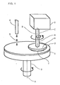
- Fig. 1 is a perspective view of the polishing apparatus in accordance with the present embodiment.
- a polishing pad 2 is adhered on a surface plate 1.
- Surface plate 1 is rotated by surface plate rotating shaft 3 that rotates about a surface plate axis A.
- a slurry duct 4 drops slurry 5 onto polishing pad 2.
- a substrate holding mechanism 6 holds a substrate 7 by suction, for example, and is rotated about substrate axis 8, by a substrate rotating shaft 8.
- Rotating mechanism 9 rotates substrate rotating shaft 8 about the substrate axis 8, and rotates the substrate axis B itself about an eccentric axis C.
- Fig. 2 is a front view of the rotating mechanism of the polishing apparatus shown in Fig. 1.
- substrate rotating shaft 8 is connected to the rotating shaft of substrate rotating motor M1 by means of a universal joint 10.
- a pulley P1 is eccentrically fixed on substrate rotating shaft 8, while a pulley P2 is fixed centered with the rotating shaft of an eccentric rotating motor M2.
- Pulley P1 and pulley P2 are linked by means of a belt 11.
- Pulleys P1, P2, universal joint 10, belt 11, substrate rotating motor M1 and eccentric rotating motor M2 constitute the rotating mechanism 9.
- substrate rotating shaft 8 rotates about the substrate axis B, through universal joint 10. Accordingly, substrate 7 held by substrate holding mechanism 6 rotates about the substrate axis B.
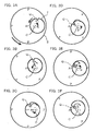
- Figs. 3A to 3F represent positional relations between the polishing pad and the substrate when the substrate is polished by the polishing apparatus and the polishing method of the present embodiment, time sequentially for the unit time period.
- polishing pad 2 rotates about the surface plate axis A.
- the reference character P is a virtual reference character to represent the state of rotation of polishing pad 2.
- the small area Q moves as represented by the thick dotted line of Fig. 3E.
- the small area Q moves in an arcuate manner as represented by the thin arrow of Fig. 3E.
- the present invention has the following characteristics.
- polishing rate increases.
- the small area Q is brought into contact with each of the abrasive grains of polishing pad 2 from various and many directions, different from the conventional polishing. Accordingly, bias wear of each abrasive grain is prevented. Further, it becomes easier to remove any clogging of the upper surface of polishing pad 2 caused by fragments of abrasive grains dropped out from the surface or fractions removed from the surface of the substrate 7. Therefore, on the upper surface of polishing pad 2, bias wear of the abrasive grains can be prevented and the clogging can be suppressed, whereby the polishing rate can be increased.
- substrate 7 revolving around the eccentric axis C at an angular velocity larger than that of rotation about the substrate axis B diffuses slurry 5 uniformly with higher efficiency.
- new abrasive grains and new chemicals can be supplied with high efficiency to each area of substrate 7, increasing the polishing rate.
- the contact area between the small area Q and polishing pad 2 increases. Further, bias wear of the abrasive grains on polishing pad 2 is prevented. Further, clogging of polishing pad 2 is suppressed. In addition, new abrasive grains and new chemicals are supplied with high efficiency to each area of substrate 7. From these factors, it becomes possible to increase the polishing rate.
- substrate axis B as an axis of the substrate rotating shaft 8 is rotated about the eccentric axis C.
- the surface plate axis A as an axis of surface plate rotating shaft 3 may be rotated about a prescribed eccentric axis D, as shown in Fig. 4.
- both the substrate axis B and the surface plate axis A may be rotated about corresponding eccentric axes (C, D), as shown in Fig. 5. This arrangement can also attain the effect of increasing the polishing rate.
- the object of processing is not limited to a silicon substrate on which buried interconnections and interlayer insulating films are formed.
- a silicon substrate on which buried interconnections and interlayer insulating films are formed may be an SOI (Silicon On Insulator) substrate, a compound semiconductor substrate, a glass substrate, a ceramic substrate or the like.
- SOI Silicon On Insulator
- the present invention is also applicable to the substrate mentioned above before the buried interconnections or films such as the interlayer insulating films are formed.
- circular rotation has been described as the rotation about the eccentric axis, it is not limiting, and elliptical rotation may be utilized.
- the polishing apparatus in accordance with the present embodiment, on the polishing pad, distance of movement of a small area of the substrate to be polished increases, and hence, the contact area between the small area and the polishing pad increases.
- the small area of the substrate to be polished is brought into contact with the polishing pad from various and many directions as compared with the conventional polishing. Accordingly, on the upper surface of the polishing pad, bias wear of abrasive grains can be prevented, and it becomes easier to remove clogging caused by fractions of abrasive grains dropped out from the upper surface of the polishing pad or fractions removed from the surface of the substrate to be polished.
- At least one of the polishing pad and the substrate to be polished revolves around an eccentric axis, at an angular velocity larger than that of rotation about the substrate axis. Therefore, slurry can be diffused uniformly with high efficiency between the polishing pad and the substrate to be polished.
- the present invention provides superior practical effects that a polishing apparatus and a polishing method that can increase the polishing rate are provided.
Landscapes
- Engineering & Computer Science (AREA)
- Mechanical Engineering (AREA)
- Finish Polishing, Edge Sharpening, And Grinding By Specific Grinding Devices (AREA)
- Mechanical Treatment Of Semiconductor (AREA)
Abstract
Description
Claims (10)
- A polishing apparatus in which a substrate to be polished (7) rotated by a substrate rotating shaft (8) is pressed against a polishing pad with a prescribed pressure while slurry (5) is supplied to an upper surface of said polishing pad (2) rotated by a surface plate rotating shaft (3), so as to polish a surface of said substrate to be polished, comprising
a rotating mechanism (9, 19) rotating at least one of a surface plate axis (A) as a rotation central axis of said surface plate rotating shaft and a substrate axis (B) as a rotation central axis of said substrate rotating shaft about corresponding prescribed eccentric axes (C, D). - The polishing apparatus according to claim 1, wherein
angular velocity of rotation of at least one of said surface plate axis (A) and said substrate axis (B) about said eccentric axes (C, D) is larger than angular velocity of rotation of said substrate to be polished (7) about said substrate axis (B). - The polishing apparatus according to claim 1, comprising
rotating mechanism (9) rotating only the substrate axis (B) of said substrate rotating shaft about a prescribed eccentric axis (C). - The polishing apparatus according to claim 1, comprising
rotating mechanism (19) rotating only the surface plate axis (A) of said surface plate rotating shaft about a prescribed eccentric axis (D). - The polishing apparatus according to claim 1, comprising
rotating mechanism (9, 19)rotating both the surface plate axis (A) of said surface plate rotating shaft and the substrate axis (B) of said substrate rotating shaft about corresponding prescribed eccentric axes (C, D). - A polishing method in which slurry (5) is supplied to an upper surface of a polishing pad (2) rotated by a surface plate rotating shaft (3), a substrate (7) to be polished is rotated by a substrate rotating shaft (8) and the substrate to be polished is pressed against said polishing pad with a prescribed pressure so that surface of said substrate to be polished is polished, comprising the step of
rotating at least on of a surface plate axis (A) as a rotation central axis of said surface plate rotating shaft and a substrate axis (B) as a rotation central axis of said substrate rotating shaft about a corresponding prescribed eccentric axes (C, D). - The polishing method according to claim 6, wherein
at least one of said surface plate axis (A) and said substrate axis (B) is rotated about corresponding said prescribed eccentric axes (C, D) with an angular velocity larger than angular velocity of rotation of said substrate to be polished (7) about said substrate axis (B). - The polishing method according to claim 6, wherein
said substrate axis (B) only is rotated about said prescribed eccentric axis (C). - The polishing method according to claim 6, wherein
said surface plate axis (A) only is rotated about said prescribed eccentric axis (D). - The polishing method according to claim 6, wherein both said surface plate axis (A) and said substrate axis (B) are rotated about corresponding prescribed eccentric axes (C, D).
Applications Claiming Priority (2)
| Application Number | Priority Date | Filing Date | Title |
|---|---|---|---|
| JP2000291728 | 2000-09-26 | ||
| JP2000291728A JP3663348B2 (en) | 2000-09-26 | 2000-09-26 | Polishing apparatus and polishing method |
Publications (2)
| Publication Number | Publication Date |
|---|---|
| EP1193032A2 true EP1193032A2 (en) | 2002-04-03 |
| EP1193032A3 EP1193032A3 (en) | 2003-12-10 |
Family
ID=18774766
Family Applications (1)
| Application Number | Title | Priority Date | Filing Date |
|---|---|---|---|
| EP01308087A Withdrawn EP1193032A3 (en) | 2000-09-26 | 2001-09-24 | Polishing apparatus and polishing method |
Country Status (3)
| Country | Link |
|---|---|
| US (1) | US6712674B2 (en) |
| EP (1) | EP1193032A3 (en) |
| JP (1) | JP3663348B2 (en) |
Cited By (2)
| Publication number | Priority date | Publication date | Assignee | Title |
|---|---|---|---|---|
| CN102019581A (en) * | 2009-09-18 | 2011-04-20 | 不二越机械工业株式会社 | Wafer grinding equipment and wafer manufacturing method |
| EP3479958A1 (en) * | 2017-11-07 | 2019-05-08 | Ebara Corporation | Substrate polishing device and polishing method |
Families Citing this family (13)
| Publication number | Priority date | Publication date | Assignee | Title |
|---|---|---|---|---|
| KR101800012B1 (en) * | 2009-09-17 | 2017-11-21 | 아사히 가라스 가부시키가이샤 | Apparatus and method for locally polishing glass substrate, and apparatus and method for producing glass product |
| CN102554758B (en) * | 2010-12-27 | 2016-06-29 | 旭硝子株式会社 | Lapping device |
| KR101552465B1 (en) | 2014-03-17 | 2015-09-10 | 한솔테크닉스(주) | Method of manufacturing substrate |
| US10076817B2 (en) | 2014-07-17 | 2018-09-18 | Applied Materials, Inc. | Orbital polishing with small pad |
| US10105812B2 (en) | 2014-07-17 | 2018-10-23 | Applied Materials, Inc. | Polishing pad configuration and polishing pad support |
| US10207389B2 (en) | 2014-07-17 | 2019-02-19 | Applied Materials, Inc. | Polishing pad configuration and chemical mechanical polishing system |
| TWI692385B (en) * | 2014-07-17 | 2020-05-01 | 美商應用材料股份有限公司 | Method, system and polishing pad for chemical mechancal polishing |
| JP6585445B2 (en) * | 2015-09-28 | 2019-10-02 | 株式会社荏原製作所 | Polishing method |
| US9873179B2 (en) | 2016-01-20 | 2018-01-23 | Applied Materials, Inc. | Carrier for small pad for chemical mechanical polishing |
| CN107186614A (en) * | 2016-03-13 | 2017-09-22 | 芜湖瑞德机械科技有限公司 | A kind of precise grinding polisher for aircraft engine seal face |
| WO2017165216A1 (en) | 2016-03-24 | 2017-09-28 | Applied Materials, Inc. | Textured small pad for chemical mechanical polishing |
| TWI837213B (en) * | 2018-11-21 | 2024-04-01 | 美商應用材料股份有限公司 | Polishing system, carrier head assembly, and method of polishing a substrate |
| US11764069B2 (en) * | 2021-06-01 | 2023-09-19 | Applied Materials, Inc. | Asymmetry correction via variable relative velocity of a wafer |
Family Cites Families (12)
| Publication number | Priority date | Publication date | Assignee | Title |
|---|---|---|---|---|
| US3172241A (en) | 1963-02-15 | 1965-03-09 | Carl J Habenicht | Lapping machine |
| DK155299B (en) | 1986-04-18 | 1989-03-20 | Struers As | APPLIANCE FOR GRINDING OR POLISHING TOPICS |
| US5554064A (en) * | 1993-08-06 | 1996-09-10 | Intel Corporation | Orbital motion chemical-mechanical polishing apparatus and method of fabrication |
| US5643053A (en) * | 1993-12-27 | 1997-07-01 | Applied Materials, Inc. | Chemical mechanical polishing apparatus with improved polishing control |
| US5624299A (en) * | 1993-12-27 | 1997-04-29 | Applied Materials, Inc. | Chemical mechanical polishing apparatus with improved carrier and method of use |
| US5820448A (en) * | 1993-12-27 | 1998-10-13 | Applied Materials, Inc. | Carrier head with a layer of conformable material for a chemical mechanical polishing system |
| US5672095A (en) * | 1995-09-29 | 1997-09-30 | Intel Corporation | Elimination of pad conditioning in a chemical mechanical polishing process |
| DE19710375C2 (en) | 1997-03-13 | 2002-11-07 | Micronas Semiconductor Holding | Process for the production of spatially structured components |
| JPH10329011A (en) * | 1997-03-21 | 1998-12-15 | Canon Inc | Precision polishing apparatus and method |
| KR100443330B1 (en) * | 1998-07-31 | 2004-08-09 | 쎄미콘테크 주식회사 | Method and apparatus for chemical mechanical polishing |
| US6184139B1 (en) * | 1998-09-17 | 2001-02-06 | Speedfam-Ipec Corporation | Oscillating orbital polisher and method |
| US6250994B1 (en) * | 1998-10-01 | 2001-06-26 | Micron Technology, Inc. | Methods and apparatuses for mechanical and chemical-mechanical planarization of microelectronic-device substrate assemblies on planarizing pads |
-
2000
- 2000-09-26 JP JP2000291728A patent/JP3663348B2/en not_active Expired - Fee Related
-
2001
- 2001-09-19 US US09/957,083 patent/US6712674B2/en not_active Expired - Fee Related
- 2001-09-24 EP EP01308087A patent/EP1193032A3/en not_active Withdrawn
Cited By (4)
| Publication number | Priority date | Publication date | Assignee | Title |
|---|---|---|---|---|
| CN102019581A (en) * | 2009-09-18 | 2011-04-20 | 不二越机械工业株式会社 | Wafer grinding equipment and wafer manufacturing method |
| CN102019581B (en) * | 2009-09-18 | 2015-03-25 | 不二越机械工业株式会社 | Wafer grinding equipment and wafer manufacturing method |
| EP3479958A1 (en) * | 2017-11-07 | 2019-05-08 | Ebara Corporation | Substrate polishing device and polishing method |
| US11331766B2 (en) | 2017-11-07 | 2022-05-17 | Ebara Corporation | Substrate polishing device and polishing method |
Also Published As
| Publication number | Publication date |
|---|---|
| US20020037685A1 (en) | 2002-03-28 |
| EP1193032A3 (en) | 2003-12-10 |
| JP2002103211A (en) | 2002-04-09 |
| US6712674B2 (en) | 2004-03-30 |
| JP3663348B2 (en) | 2005-06-22 |
Similar Documents
| Publication | Publication Date | Title |
|---|---|---|
| US6712674B2 (en) | Polishing apparatus and polishing method | |
| US5554064A (en) | Orbital motion chemical-mechanical polishing apparatus and method of fabrication | |
| US5216843A (en) | Polishing pad conditioning apparatus for wafer planarization process | |
| US5941758A (en) | Method and apparatus for chemical-mechanical polishing | |
| US6951512B2 (en) | Chemical mechanical polishing apparatus and method of chemical mechanical polishing | |
| KR100298823B1 (en) | Polishing apparatus and method | |
| JP2798347B2 (en) | Wafer notch polishing machine | |
| US6730191B2 (en) | Coaxial dressing for chemical mechanical polishing | |
| US20010000497A1 (en) | Method and apparatus for removing a material layer from a substrate | |
| US6180423B1 (en) | Method for wafer polishing and method for polishing pad dressing | |
| US6116991A (en) | Installation for improving chemical-mechanical polishing operation | |
| WO1996024467A1 (en) | Chemical-mechanical polishing using curved carriers | |
| US20020155795A1 (en) | Optical endpoint detection for buff module on CMP tool | |
| US20030077986A1 (en) | Front-reference carrier on orbital solid platen | |
| JP3360488B2 (en) | Polishing apparatus and polishing method using the same | |
| JP2004502311A (en) | Projection type gimbal point drive | |
| US6929533B2 (en) | Methods for enhancing within-wafer CMP uniformity | |
| JP3489272B2 (en) | Polishing apparatus and polishing method using the same | |
| US6733373B1 (en) | Polishing assembly for a linear chemical mechanical polishing apparatus and method for forming | |
| US6716299B1 (en) | Profiled retaining ring for chemical mechanical planarization | |
| JP2001009710A (en) | Wafer polishing equipment | |
| US6409587B1 (en) | Dual-hardness polishing pad for linear polisher and method for fabrication | |
| US6386960B1 (en) | Chemical-mechanical polishing method and apparatus | |
| KR100239752B1 (en) | Chemical mechanical polishing apparatus | |
| KR200267224Y1 (en) | Chemical Mechanical Polishing apparatus for semiconductor wafer |
Legal Events
| Date | Code | Title | Description |
|---|---|---|---|
| PUAI | Public reference made under article 153(3) epc to a published international application that has entered the european phase |
Free format text: ORIGINAL CODE: 0009012 |
|
| AK | Designated contracting states |
Kind code of ref document: A2 Designated state(s): AT BE CH CY DE DK ES FI FR GB GR IE IT LI LU MC NL PT SE TR |
|
| AX | Request for extension of the european patent |
Free format text: AL;LT;LV;MK;RO;SI |
|
| PUAL | Search report despatched |
Free format text: ORIGINAL CODE: 0009013 |
|
| AK | Designated contracting states |
Kind code of ref document: A3 Designated state(s): AT BE CH CY DE DK ES FI FR GB GR IE IT LI LU MC NL PT SE TR |
|
| AX | Request for extension of the european patent |
Extension state: AL LT LV MK RO SI |
|
| 17P | Request for examination filed |
Effective date: 20040121 |
|
| 17Q | First examination report despatched |
Effective date: 20040326 |
|
| AKX | Designation fees paid |
Designated state(s): DE GB NL |
|
| STAA | Information on the status of an ep patent application or granted ep patent |
Free format text: STATUS: THE APPLICATION IS DEEMED TO BE WITHDRAWN |
|
| 18D | Application deemed to be withdrawn |
Effective date: 20060403 |