EP1192972A2 - Elektrisch aktives Implantat - Google Patents
Elektrisch aktives Implantat Download PDFInfo
- Publication number
- EP1192972A2 EP1192972A2 EP01250337A EP01250337A EP1192972A2 EP 1192972 A2 EP1192972 A2 EP 1192972A2 EP 01250337 A EP01250337 A EP 01250337A EP 01250337 A EP01250337 A EP 01250337A EP 1192972 A2 EP1192972 A2 EP 1192972A2
- Authority
- EP
- European Patent Office
- Prior art keywords
- implant
- packaging
- energy
- specific data
- implant according
- Prior art date
- Legal status (The legal status is an assumption and is not a legal conclusion. Google has not performed a legal analysis and makes no representation as to the accuracy of the status listed.)
- Granted
Links
- 239000007943 implant Substances 0.000 title claims abstract description 166
- 230000003213 activating effect Effects 0.000 claims abstract description 11
- 238000004806 packaging method and process Methods 0.000 claims description 16
- 230000009849 deactivation Effects 0.000 claims description 8
- 230000000903 blocking effect Effects 0.000 claims description 6
- 238000004519 manufacturing process Methods 0.000 claims description 5
- 230000007420 reactivation Effects 0.000 claims description 5
- 239000003795 chemical substances by application Substances 0.000 claims description 3
- 230000004913 activation Effects 0.000 description 17
- 238000001994 activation Methods 0.000 description 17
- 238000002513 implantation Methods 0.000 description 11
- 235000014676 Phragmites communis Nutrition 0.000 description 9
- 230000005611 electricity Effects 0.000 description 7
- 238000004891 communication Methods 0.000 description 5
- 230000006870 function Effects 0.000 description 5
- 238000012790 confirmation Methods 0.000 description 2
- 230000001419 dependent effect Effects 0.000 description 2
- 238000010586 diagram Methods 0.000 description 2
- 239000000284 extract Substances 0.000 description 2
- 230000003993 interaction Effects 0.000 description 2
- 230000009467 reduction Effects 0.000 description 2
- 238000013475 authorization Methods 0.000 description 1
- 230000008901 benefit Effects 0.000 description 1
- 230000005540 biological transmission Effects 0.000 description 1
- 239000002981 blocking agent Substances 0.000 description 1
- 230000008859 change Effects 0.000 description 1
- 238000000605 extraction Methods 0.000 description 1
- 230000005764 inhibitory process Effects 0.000 description 1
- 238000007689 inspection Methods 0.000 description 1
- 230000002427 irreversible effect Effects 0.000 description 1
- 239000002184 metal Substances 0.000 description 1
- 238000000034 method Methods 0.000 description 1
- 230000008569 process Effects 0.000 description 1
- 230000002441 reversible effect Effects 0.000 description 1
- 230000001954 sterilising effect Effects 0.000 description 1
- 238000004659 sterilization and disinfection Methods 0.000 description 1
- 238000012360 testing method Methods 0.000 description 1
- 230000032258 transport Effects 0.000 description 1
- 230000001960 triggered effect Effects 0.000 description 1
- 230000002861 ventricular Effects 0.000 description 1
Images

Classifications
-
- A—HUMAN NECESSITIES
- A61—MEDICAL OR VETERINARY SCIENCE; HYGIENE
- A61N—ELECTROTHERAPY; MAGNETOTHERAPY; RADIATION THERAPY; ULTRASOUND THERAPY
- A61N1/00—Electrotherapy; Circuits therefor
- A61N1/18—Applying electric currents by contact electrodes
- A61N1/32—Applying electric currents by contact electrodes alternating or intermittent currents
- A61N1/36—Applying electric currents by contact electrodes alternating or intermittent currents for stimulation
- A61N1/372—Arrangements in connection with the implantation of stimulators
- A61N1/378—Electrical supply
-
- A—HUMAN NECESSITIES
- A61—MEDICAL OR VETERINARY SCIENCE; HYGIENE
- A61N—ELECTROTHERAPY; MAGNETOTHERAPY; RADIATION THERAPY; ULTRASOUND THERAPY
- A61N1/00—Electrotherapy; Circuits therefor
- A61N1/18—Applying electric currents by contact electrodes
- A61N1/32—Applying electric currents by contact electrodes alternating or intermittent currents
- A61N1/36—Applying electric currents by contact electrodes alternating or intermittent currents for stimulation
- A61N1/372—Arrangements in connection with the implantation of stimulators
Definitions
- the present invention relates to an electrically active implant that uses energy Components and activation means for activating the implant having.
- the implant After the completion of an implant such as a pacemaker or a defibrillator and before its implantation, the implant is usually stored.
- the typical power consumption is one in the
- the pacemaker in storage is about 8 ⁇ A after implantation depending on programming and degree of inhibition between 12 and 22 ⁇ A. It follows that two years of storage time is about a year of implantation correspond. As a result, the electricity consumed during storage cannot be used more during the implantation period, so the actual Useful life of the implant, namely the implantation time, is reduced.
- the current use-before date i.e. the date before which the implant must be put into operation depends on the date of the battery connection, the sterilization date, a product-specific period of time and also takes into account power consumption during storage.
- the Use-Before dates are implanted devices for resterilization to the Manufacturer sent back. It can happen that during the implants removed from storage are no longer regular sales products can be delivered. Apart from the battery condition essentially no reasons exist for a maximum use-before period of for example 24 months.
- the use-before period could be through Extended reduction in electricity consumed during storage the number of implants returned for resterilization and the number of units to be scrapped could be reduced.
- pacemakers and especially that of all defibrillators is temperature dependent. If during storage or transportation Temperatures below 5 ° C, for example, occur with a Mostly reversible but also irreversible errors can be expected. so damaged units can usually no longer be delivered regularly, since the power consumption after the error occurred and thus the battery condition cannot be determined with sufficient accuracy.
- An implant is known from US Pat. No. 5,522,856, which has selected circuit elements the implant in a power-saving mode until the Implant is implanted in a patient.
- the known implant also has a detector that determines whether the implant is connected for implantation becomes. If such an implantation is detected, the Circuit elements of the pacemaker in the normal current-consuming Operating mode offset.
- the implant can also be removed from the warehouse and tested for its function and then returned to the warehouse be brought back, the implant again in an energy-saving Stand-by mode is set to reduce power consumption during storage to reduce. Furthermore, the implant detects when the impedance to the Electrodes falls below a predetermined level. If this has occurred the implant remains permanently in the normal operating mode.
- US 5,350,407 discloses an implant which is both in a waiting state Dependency on an instruction from an external communication device as well as in an active state depending on removal of a Activation pen or depending on an activation instruction from one external communication device is operable. After manufacturing the The activation pin is inserted into the implant and the external one Communication device is triggered to issue a deactivation instruction to transmit the implant. The power supply for part of the Circuit elements of the implant are switched off while the power supply for those circuit elements are maintained which are used to activate the remaining circuit elements in connection with the communication operation required are. The implant is either transferred by a Activation instruction from an external communication device or by Activation pin removal activated.
- the invention is based on the idea of having an electrically active implant energy-consuming components and with activating agent to activate the To provide implants. Furthermore, the electrically active implant has deactivating means to deactivate the energy-consuming components of the implant on, taking the energy-consuming components of the implant during its storage can be deactivated by means of the deactivating means. Furthermore, the Implant a means for the non-volatile storage of implant-specific Dates on.
- the advantages associated with the invention are in particular that all energy-consuming components of the Implants can be deactivated or switched off, so that no current in the the implant flows during its storage. It also ensures that necessary implant-specific data even when all energy consuming devices are switched off Components of the implant are preserved.
- An embodiment of the invention provides that the means for storing one represent non-volatile electronic memory in which the implant-specific Data after the manufacture of the implant in the electronic non-volatile Memory can be written. Those in this electronic store saved data can be easily created after activation of the implant read out again.
- the means for storing a barcode depicted on the implant which shows the implant-specific Data included.
- the implant-specific data can also be entered here Extract again after activation of the implant.
- the Barcode containing implant-specific data also on the packaging of the Implants are attached.
- the activating means at least one wirelessly activated switch, which is used to reactivate the deactivated energy-consuming components.
- This switch can activated magnetically or telemetrically. With the help of wireless Activatable switch can be reactivated without intervention in the implant be performed.
- implant-specific data are located on the implant or a barcode on the packaging of the implant external barcode scanner read out, after which the implant-specific data be extracted and sent to the. using an external telemetric transmitter Implant are transmitted.
- the transmitted implant-specific data are stored in a memory in the implant. That way you can the implant-specific data is subsequently saved in the implant become.
- a particularly preferred embodiment comprises an implant with a magnetically activated switch and a packaging containing a magnet comprises, which is arranged so that the magnetically activated switch of the Implant is always activated when the implant packaging is removed. This enables the implant to be activated automatically removal from the packaging before implantation.
- the implant has a reactivation blocking means to block repeated activations or deactivation of the energy-consuming components of the implant. This is said to prevent that the implant is repeatedly activated or deactivated without authorization.
- FIG 1 is a first embodiment of an electrically active implant shown.
- the implant has a battery 1, activation / deactivation means 2 Reactivating blocking means 5, which is connected to the activating / deactivating means 2, conventional energy-consuming components 3 of the implant, and one non-volatile electronic memory 4.
- implant-specific data such as for example the serial number of the implant and the factory exit program stored in the non-volatile electronic memory 4.
- the data stored in the memory 4 remain even when the current and power supply, so that after activation of the Implants can be used again
- the implantation time i.e. the Time during which the implant is implanted in the body can be extended.
- the energy-consuming device is activated Components 3.
- the activation is done by means of a small one in the Blister pack carried magnets, which one in the implant located REED switch operated. When removing the implant from the The REED switch closes the blister pack and activates, for example Pacemaker function.
- the implant works in this function or operating mode in normal operation. In other words, the energy-consuming components 3 of the implant are powered by the battery 1, so that Implant can perform all functions and on which in the memory 4 stored implant-specific information.
- Implant a reactivating blocking means 5 controls the circuits of the implant in such a way that they are deactivated again the user is excluded and only used by the employee a special telemetric transmitter is possible.
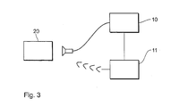
- FIGS. 2 and 3 show an implant according to a second exemplary embodiment (Fig. 2) and the interaction of its components (Fig. 3) shown.
- the implant has a battery 1, an activation / deactivation means 2, energy-consuming Components 3, a reactivation blocking means 5 and a memory 6 on.
- no data is sent after the factory exit check stored in the implant.
- the implant is completely switched off, see above that it does not consume electricity during storage.
- the implant-specific data are encoded and in a bar code converted. This barcode is then on the implant or on the Packaging of the implant attached.
- the battery 1 from the energy consuming Components 3 of the implant using the activation / deactivation agent 2 separate.
- This external programming device 12 has 3, a barcode scanner 10 and a telemetric transmitter 11.
- the barcode scanner reads on the implant or on the packaging of the Barcode, extracts the implant-specific data and sends this data telemetrically to the implant, where it is in memory 6 can be stored for further use.
- the transmitted by the transmitter 11 Information is received and received by a receiver 7 of the implant forwarded to memory 6 where they are stored.
- the barcode is constantly scanned during steps 1 to 6.
- Kick one Change to e.g. removal of the barcode, so the initialization process canceled immediately and without confirmation.
- the activation of the implant after delivery is similar to that Embodiment of FIG. 1 by a magnetic pad that a REED switch closes, whereby the energy-consuming components 3 of the implant the battery 1 can be coupled so as to be supplied with current and voltage become.
- the REED switch is permanently bridged achieved, for example, by a thermocouple.
- the thermocouple can be designed as a bi-metal switch. Through permanent bridging can prevent erroneous deactivation in the implanted state become.
- Such bridging of the REED switch can of course also in the first embodiment.
- the factory exit program and the serial number of the implant in a separate one Storage of the implant can be stored, which is continuously under tension is supplied. All other energy-consuming components of the implant such as CPU, charge pumps, output stages or the like, are completely deactivated or switched off after the factory exit test.
- a REED switch in the implant operated by a small magnet, which is in the blister.
- removing the implant from the Blister closes the REED switch and thus activates the normal operating mode of the Implant by adding the energy consuming components of the implant the battery are coupled, which provides them with current and voltage become.
- Another deactivation of the implant by opening the REED switch by a further application of a magnet is by a reactivating blocking agent prevented.
- This pen or connector when removed before implantation, causes in the Implant the ventricular different contact with the indifferent contact is briefly connected with low resistance. This signal is from the control electronics of the implant for permanent activation of the full functionality.
- the implant can be activated by a lying electrode is connected to the implant.
- the electronics of the implant record one external load, which is less than 3200 ohms, which means full functionality is permanently activated.
Landscapes
- Health & Medical Sciences (AREA)
- Engineering & Computer Science (AREA)
- Biomedical Technology (AREA)
- Nuclear Medicine, Radiotherapy & Molecular Imaging (AREA)
- Radiology & Medical Imaging (AREA)
- Life Sciences & Earth Sciences (AREA)
- Animal Behavior & Ethology (AREA)
- General Health & Medical Sciences (AREA)
- Public Health (AREA)
- Veterinary Medicine (AREA)
- Electrotherapy Devices (AREA)
- Prostheses (AREA)
- Pharmaceuticals Containing Other Organic And Inorganic Compounds (AREA)
- Compounds Of Unknown Constitution (AREA)
- Hybrid Cells (AREA)
- Connection Of Batteries Or Terminals (AREA)
Abstract
Description
- Figur 1
- ein schematisches Blockschaltbild eines Implantates gemäß einem ersten Ausführungsbeispiel,
- Figur 2
- ein schematisches Blockschaltbild eines Implantates gemäß einem zweiten Ausführungsbeispiel, und
- Figur 3
- eine Darstellung des Zusammenwirkens der Komponenten des zweiten Ausführungsbeispiels.
Claims (13)
- Elektrisch aktives Implantat mit energie-verbrauchenden Komponenten (3), und Aktiviermittel (2) zum Aktivieren des Implantats, gekennzeichnet durch Deaktiviermittel (2) zum Deaktivieren der energie-verbrauchenden Komponenten (3) des Implantats, wobei die energie-verbrauchenden Komponenten (3) des Implantats während seiner Lagerung mittels des Deaktiviermittels (2) deaktivierbar sind, und ein Mittel (4) zum nicht-flüchtigen Speichern von implantat-spezifischen Daten.
- Implantat nach Anspruch 1, dadurch gekennzeichnet, dass das Mittel zum Speichern (4) als nicht-flüchtiger elektronischer Speicher (4) ausgestaltet ist, wobei die implantat-spezifischen Daten nach der Herstellung das Implantats in dem elektronischen nicht-flüchtigen Speicher (4) einschreibbar sind.
- Implantat nach Anspruch 1, dadurch gekennzeichnet, dass das Mittel zum Speichern einen auf dem Implantat abgebildeten Strichcode enthält, welcher implantat-spezifische Daten beinhaltet.
- Implantat nach Anspruch 1 in einer Verpackungshülle, dadurch gekennzeichnet, dass das Speichermittel einen implantat-spezifische Daten enthaltenden Strichcode enthält, welcher an der Verpackung des Implantat anbringbar ausgestaltet ist.
- Implantat nach einem der vorherigen Ansprüche, dadurch gekennzeichnet, dass das Aktiviermittel (2) mindestens einen drahtlos aktivierbaren Schalter aufweist, welcher zur Reaktivierung der deaktivierten energie-verbrauchenden Komponenten (3) dient.
- Implantat nach Anspruch 5, dadurch gekennzeichnet, dass der Schalter magnetisch aktivierbar ist.
- Implantat nach Anspruch 5, dadurch gekennzeichnet, dass der Schalter telemetrisch aktivierbar ist.
- Implantat nach Anspruch 3 oder 4, dadurch gekennzeichnet, dass der Strichcode von einem externen Barcode-Scanner (10) gelesen wird, die implantat-spezifischen Daten extrahiert werden und mittels eines externen telemetrischen Senders (11) an des Implantat übermittelt wird, und die übermittelten implantat-spezifischen Daten in einem zweiten Speicher (6) in dem Implantat gespeichert werden.
- Implantat nach einem der Ansprüche 5 bis 8, gekennzeichnet durch ein Reaktivier-Sperrmittel (5) zum Sperren von wiederholten Reaktivierungen der energie-verbrauchenden Komponenten (3) des Implantats.
- Implantat nach einem der vorherigen Ansprüche, dadurch gekennzeichnet, dass das Deaktiviermittel (2) mindestens einen drahtlos aktivierbaren Schalter aufweist.
- Implantat nach einem der vorherigen Ansprüche, wobei das Aktiviermittel und das Deaktiviermittel als ein einzelnes Mittel (2) ausgebildet ist.
- Implantat nach Anspruch 6 und Verpackung, dadurch gekennzeichnet, dass die Verpackung einen Magneten enthält, der so angeordnet ist, dass der Schalter beim Entnehmen des Implantates aus der Verpackung aktiviert wird.
- Verpackung für ein Implantat nach Anspruch 6, dadurch gekennzeichnet, dass die Verpackung einen Magneten enthält, der angeordnet ist, einen Schalter des Implantates zu aktivieren, während dieses aus der Verpackung entnommen wird.
Applications Claiming Priority (2)
| Application Number | Priority Date | Filing Date | Title |
|---|---|---|---|
| DE10049727A DE10049727A1 (de) | 2000-09-28 | 2000-09-28 | Elektrisch aktives Implantat |
| DE10049727 | 2000-09-28 |
Publications (3)
| Publication Number | Publication Date |
|---|---|
| EP1192972A2 true EP1192972A2 (de) | 2002-04-03 |
| EP1192972A3 EP1192972A3 (de) | 2003-02-05 |
| EP1192972B1 EP1192972B1 (de) | 2006-06-14 |
Family
ID=7659012
Family Applications (1)
| Application Number | Title | Priority Date | Filing Date |
|---|---|---|---|
| EP01250337A Expired - Lifetime EP1192972B1 (de) | 2000-09-28 | 2001-09-25 | Elektrisch aktives Implantat |
Country Status (4)
| Country | Link |
|---|---|
| US (1) | US6917831B2 (de) |
| EP (1) | EP1192972B1 (de) |
| AT (1) | ATE329652T1 (de) |
| DE (2) | DE10049727A1 (de) |
Cited By (9)
| Publication number | Priority date | Publication date | Assignee | Title |
|---|---|---|---|---|
| EP1277493A3 (de) * | 2001-07-20 | 2003-04-23 | BIOTRONIK Mess- und Therapiegeräte GmbH & Co Ingenieurbüro Berlin | Medizinisches Einweggerät |
| US9615788B2 (en) | 2012-08-31 | 2017-04-11 | Nuvectra Corporation | Method and system of producing 2D representations of 3D pain and stimulation maps and implant models on a clinician programmer |
| US9767255B2 (en) | 2012-09-05 | 2017-09-19 | Nuvectra Corporation | Predefined input for clinician programmer data entry |
| US9776007B2 (en) | 2012-08-31 | 2017-10-03 | Nuvectra Corporation | Method and system of quick neurostimulation electrode configuration and positioning |
| US9901740B2 (en) | 2012-08-31 | 2018-02-27 | Nuvectra Corporation | Clinician programming system and method |
| US10083261B2 (en) | 2012-08-31 | 2018-09-25 | Nuvectra Corporation | Method and system of simulating a pulse generator on a clinician programmer |
| US10141076B2 (en) | 2012-08-31 | 2018-11-27 | Nuvectra Corporation | Programming and virtual reality representation of stimulation parameter groups |
| US10376701B2 (en) | 2012-08-31 | 2019-08-13 | Nuvectra Corporation | Touch screen safety controls for clinician programmer |
| US10668276B2 (en) | 2012-08-31 | 2020-06-02 | Cirtec Medical Corp. | Method and system of bracketing stimulation parameters on clinician programmers |
Families Citing this family (24)
| Publication number | Priority date | Publication date | Assignee | Title |
|---|---|---|---|---|
| US7470288B2 (en) * | 2003-07-11 | 2008-12-30 | Depuy Products, Inc. | Telemetric tibial tray |
| US7190273B2 (en) * | 2003-07-11 | 2007-03-13 | Depuy Products, Inc. | Joint endoprosthesis with ambient condition sensing |
| US7195645B2 (en) * | 2003-07-11 | 2007-03-27 | Depuy Products, Inc. | In vivo joint space measurement device and method |
| US7571008B2 (en) * | 2003-08-18 | 2009-08-04 | Medtronic, Inc. | System and apparatus for remote activation of implantable medical devices |
| US8014872B2 (en) * | 2003-08-18 | 2011-09-06 | Medtronic, Inc. | System and apparatus for controlled activation of acute use medical devices |
| US9205255B2 (en) | 2004-06-10 | 2015-12-08 | Medtronic Urinary Solutions, Inc. | Implantable pulse generator systems and methods for providing functional and/or therapeutic stimulation of muscles and/or nerves and/or central nervous system tissue |
| US8165692B2 (en) * | 2004-06-10 | 2012-04-24 | Medtronic Urinary Solutions, Inc. | Implantable pulse generator power management |
| US9308382B2 (en) | 2004-06-10 | 2016-04-12 | Medtronic Urinary Solutions, Inc. | Implantable pulse generator systems and methods for providing functional and/or therapeutic stimulation of muscles and/or nerves and/or central nervous system tissue |
| US9480846B2 (en) | 2006-05-17 | 2016-11-01 | Medtronic Urinary Solutions, Inc. | Systems and methods for patient control of stimulation systems |
| WO2013067538A1 (en) | 2011-11-04 | 2013-05-10 | Nevro Corporation | Medical device communication and charding assemblies for use with implantable signal generators |
| US9227076B2 (en) | 2011-11-04 | 2016-01-05 | Nevro Corporation | Molded headers for implantable signal generators, and associated systems and methods |
| US8611995B2 (en) | 2012-04-19 | 2013-12-17 | Cochlear Limited | Enabling device for implantable medical devices |
| US8983616B2 (en) | 2012-09-05 | 2015-03-17 | Greatbatch Ltd. | Method and system for associating patient records with pulse generators |
| US8761897B2 (en) | 2012-08-31 | 2014-06-24 | Greatbatch Ltd. | Method and system of graphical representation of lead connector block and implantable pulse generators on a clinician programmer |
| US9180302B2 (en) | 2012-08-31 | 2015-11-10 | Greatbatch Ltd. | Touch screen finger position indicator for a spinal cord stimulation programming device |
| US8868199B2 (en) | 2012-08-31 | 2014-10-21 | Greatbatch Ltd. | System and method of compressing medical maps for pulse generator or database storage |
| US9594877B2 (en) | 2012-08-31 | 2017-03-14 | Nuvectra Corporation | Virtual reality representation of medical devices |
| US8812125B2 (en) | 2012-08-31 | 2014-08-19 | Greatbatch Ltd. | Systems and methods for the identification and association of medical devices |
| US8757485B2 (en) | 2012-09-05 | 2014-06-24 | Greatbatch Ltd. | System and method for using clinician programmer and clinician programming data for inventory and manufacturing prediction and control |
| EP3903875A1 (de) | 2014-05-20 | 2021-11-03 | Nevro Corporation | Implantierte pulsgeneratoren mit reduziertem leistungsverbrauch über signalstärke-/signaldauereigenschaften sowie entsprechende systeme und verfahren |
| EP3191176B1 (de) * | 2014-10-22 | 2024-04-10 | Nevro Corp. | Systeme und verfahren zur verlängerung der lebensdauer einer implantierten pulserzeugungsbatterie |
| US9517344B1 (en) | 2015-03-13 | 2016-12-13 | Nevro Corporation | Systems and methods for selecting low-power, effective signal delivery parameters for an implanted pulse generator |
| EP3737459A4 (de) | 2018-01-30 | 2021-10-20 | Nevro Corp. | Effiziente verwendung einer implantierbaren pulsgeneratorbatterie und zugehörige systeme und verfahren |
| US10933238B2 (en) | 2019-01-31 | 2021-03-02 | Nevro Corp. | Power control circuit for sterilized devices, and associated systems and methods |
Citations (2)
| Publication number | Priority date | Publication date | Assignee | Title |
|---|---|---|---|---|
| US5350407A (en) | 1992-12-30 | 1994-09-27 | Telectronics Pacing Systems, Inc. | Implantable stimulator having quiescent and active modes of operation |
| US5522856A (en) | 1994-09-20 | 1996-06-04 | Vitatron Medical, B.V. | Pacemaker with improved shelf storage capacity |
Family Cites Families (12)
| Publication number | Priority date | Publication date | Assignee | Title |
|---|---|---|---|---|
| US5080096A (en) | 1990-07-06 | 1992-01-14 | Medtronic, Inc. | Method and apparatus for accessing a nonvolatile memory |
| DE4139122C1 (de) | 1991-11-28 | 1993-04-08 | Fenzlein, Paul-Gerhard, 8500 Nuernberg, De | |
| EP0560470A1 (de) | 1992-03-07 | 1993-09-15 | Oxley Developments Company Limited | Sicherheitssystem |
| SE9201745D0 (sv) * | 1992-06-05 | 1992-06-05 | Siemens Elema Ab | Pacemaker |
| US5342408A (en) * | 1993-01-07 | 1994-08-30 | Incontrol, Inc. | Telemetry system for an implantable cardiac device |
| WO1995016313A1 (en) * | 1993-12-08 | 1995-06-15 | Michael Jeremy Kew | A communications system and associated apparatus |
| DE19758393B4 (de) * | 1997-12-23 | 2006-04-20 | Biotronik Meß- und Therapiegeräte GmbH & Co. Ingenieurbüro Berlin | Anordnung zur Patientenüberwachung |
| FR2781905B1 (fr) | 1998-07-30 | 2002-09-13 | Claude Perles | Procede de suivi operatoire lors de la pose d'implants |
| US6016448A (en) * | 1998-10-27 | 2000-01-18 | Medtronic, Inc. | Multilevel ERI for implantable medical devices |
| AU4335700A (en) | 1999-04-07 | 2000-10-23 | Endonetics, Inc. | Implantable monitoring probe |
| US6285897B1 (en) | 1999-04-07 | 2001-09-04 | Endonetics, Inc. | Remote physiological monitoring system |
| IL132944A (en) | 1999-11-15 | 2009-05-04 | Arkady Glukhovsky | Method for running a photo collection process |
-
2000
- 2000-09-28 DE DE10049727A patent/DE10049727A1/de not_active Withdrawn
-
2001
- 2001-09-25 DE DE50110127T patent/DE50110127D1/de not_active Expired - Lifetime
- 2001-09-25 AT AT01250337T patent/ATE329652T1/de not_active IP Right Cessation
- 2001-09-25 US US09/963,109 patent/US6917831B2/en not_active Expired - Lifetime
- 2001-09-25 EP EP01250337A patent/EP1192972B1/de not_active Expired - Lifetime
Patent Citations (2)
| Publication number | Priority date | Publication date | Assignee | Title |
|---|---|---|---|---|
| US5350407A (en) | 1992-12-30 | 1994-09-27 | Telectronics Pacing Systems, Inc. | Implantable stimulator having quiescent and active modes of operation |
| US5522856A (en) | 1994-09-20 | 1996-06-04 | Vitatron Medical, B.V. | Pacemaker with improved shelf storage capacity |
Cited By (11)
| Publication number | Priority date | Publication date | Assignee | Title |
|---|---|---|---|---|
| EP1277493A3 (de) * | 2001-07-20 | 2003-04-23 | BIOTRONIK Mess- und Therapiegeräte GmbH & Co Ingenieurbüro Berlin | Medizinisches Einweggerät |
| US7236827B2 (en) | 2001-07-20 | 2007-06-26 | Biotronik Mess- Und Therapiegeraete Gmbh & Co. Ingenieurbuero Berlin | Single-use medical device |
| US9615788B2 (en) | 2012-08-31 | 2017-04-11 | Nuvectra Corporation | Method and system of producing 2D representations of 3D pain and stimulation maps and implant models on a clinician programmer |
| US9776007B2 (en) | 2012-08-31 | 2017-10-03 | Nuvectra Corporation | Method and system of quick neurostimulation electrode configuration and positioning |
| US9901740B2 (en) | 2012-08-31 | 2018-02-27 | Nuvectra Corporation | Clinician programming system and method |
| US10083261B2 (en) | 2012-08-31 | 2018-09-25 | Nuvectra Corporation | Method and system of simulating a pulse generator on a clinician programmer |
| US10141076B2 (en) | 2012-08-31 | 2018-11-27 | Nuvectra Corporation | Programming and virtual reality representation of stimulation parameter groups |
| US10347381B2 (en) | 2012-08-31 | 2019-07-09 | Nuvectra Corporation | Programming and virtual reality representation of stimulation parameter groups |
| US10376701B2 (en) | 2012-08-31 | 2019-08-13 | Nuvectra Corporation | Touch screen safety controls for clinician programmer |
| US10668276B2 (en) | 2012-08-31 | 2020-06-02 | Cirtec Medical Corp. | Method and system of bracketing stimulation parameters on clinician programmers |
| US9767255B2 (en) | 2012-09-05 | 2017-09-19 | Nuvectra Corporation | Predefined input for clinician programmer data entry |
Also Published As
| Publication number | Publication date |
|---|---|
| DE50110127D1 (de) | 2006-07-27 |
| US6917831B2 (en) | 2005-07-12 |
| DE10049727A1 (de) | 2002-04-11 |
| US20020068956A1 (en) | 2002-06-06 |
| EP1192972A3 (de) | 2003-02-05 |
| ATE329652T1 (de) | 2006-07-15 |
| EP1192972B1 (de) | 2006-06-14 |
Similar Documents
| Publication | Publication Date | Title |
|---|---|---|
| EP1192972B1 (de) | Elektrisch aktives Implantat | |
| DE10117241B4 (de) | Vorrichtung zur Ermöglichung einer unmittelbaren Abfrage von Informationen und einer Identifikation von einer implantierbaren medizinischen Vorrichtung mit einer verbrauchten Energiequelle | |
| DE69405869T2 (de) | Fehlertolerante elective ersetzungsindikation für medizinische implantierbare vorrichtung | |
| DE69008516T2 (de) | In ein lebewesen implantierbares elektromedizinisches gerät. | |
| DE69417609T2 (de) | Räumlich getrennte Kontrollvorrichtung für einen implantierbaren Stimulator für das Gewebewachstum | |
| DE69123429T2 (de) | Implantierbarer Defibrillator mit Mitteln zum Erfassen von Leckströmen | |
| DE60014107T2 (de) | Detektion des zustandes einer batterie | |
| DE69820015T2 (de) | Apparat zur Wartung der Batterie für tragbare elektronische Einrichtungen | |
| DE69404844T2 (de) | Telemetriesystem für einen herzschrittmacher | |
| DE69311658T2 (de) | Kontaktloses Übertragungssystem | |
| DE69633211T2 (de) | Implantierbare Herzstimulationseinrichtung | |
| DE60035195T3 (de) | System zur übermittlung von betriebsdaten zwischen einer elektrischen zahnbürste und einer separaten bedieneinheit | |
| DE3145149C2 (de) | ||
| EP0811398B1 (de) | Implantierbares Stimulationsgerät | |
| DE69122484T2 (de) | Verfahren und gerät zum zugreifen auf einen nichtflüchtigen speicher | |
| DE69019139T2 (de) | Intelligentes System für eine Batterie. | |
| DE3850744T2 (de) | Tragbares Medium mit elektrischer Stromversorgung. | |
| DE69325411T2 (de) | Batteriebetriebener Rechner mit Batteriestandmesser und Vorrichtung zur Messung des Ladestandes einer Batterie | |
| DE69304996T2 (de) | Herzschrittmacher | |
| DE3801699C2 (de) | ||
| DE69817543T2 (de) | Automatische Datenrückgewinnung in Chipkarten | |
| DE69830203T2 (de) | Implantierbare medizinische vorrichtung mit hochfrequenz-einkopplung zum aufladen der energiequelle | |
| DE20022651U1 (de) | Vorrichtung zum Erfassen der Temperatur bei einer implantierbaren Pumpe | |
| DE3218733A1 (de) | Einpflanzbare einrichtung mit mikroprozessorsteuerung | |
| DE60312704T2 (de) | Elektronische Datenverarbeitungseinrichtung |
Legal Events
| Date | Code | Title | Description |
|---|---|---|---|
| PUAI | Public reference made under article 153(3) epc to a published international application that has entered the european phase |
Free format text: ORIGINAL CODE: 0009012 |
|
| AK | Designated contracting states |
Kind code of ref document: A2 Designated state(s): AT BE CH CY DE DK ES FI FR GB GR IE IT LI LU MC NL PT SE TR |
|
| AX | Request for extension of the european patent |
Free format text: AL;LT;LV;MK;RO;SI |
|
| PUAL | Search report despatched |
Free format text: ORIGINAL CODE: 0009013 |
|
| AK | Designated contracting states |
Designated state(s): AT BE CH CY DE DK ES FI FR GB GR IE IT LI LU MC NL PT SE TR |
|
| AX | Request for extension of the european patent |
Extension state: AL LT LV MK RO SI |
|
| 17P | Request for examination filed |
Effective date: 20030402 |
|
| AKX | Designation fees paid |
Designated state(s): AT BE CH CY DE DK ES FI FR GB GR IE IT LI LU MC NL PT SE TR |
|
| 17Q | First examination report despatched |
Effective date: 20040423 |
|
| GRAP | Despatch of communication of intention to grant a patent |
Free format text: ORIGINAL CODE: EPIDOSNIGR1 |
|
| GRAS | Grant fee paid |
Free format text: ORIGINAL CODE: EPIDOSNIGR3 |
|
| GRAA | (expected) grant |
Free format text: ORIGINAL CODE: 0009210 |
|
| RAP1 | Party data changed (applicant data changed or rights of an application transferred) |
Owner name: BIOTRONIK GMBH & CO. KG |
|
| AK | Designated contracting states |
Kind code of ref document: B1 Designated state(s): AT BE CH CY DE DK ES FI FR GB GR IE IT LI LU MC NL PT SE TR |
|
| PG25 | Lapsed in a contracting state [announced via postgrant information from national office to epo] |
Ref country code: IE Free format text: LAPSE BECAUSE OF FAILURE TO SUBMIT A TRANSLATION OF THE DESCRIPTION OR TO PAY THE FEE WITHIN THE PRESCRIBED TIME-LIMIT Effective date: 20060614 Ref country code: FI Free format text: LAPSE BECAUSE OF FAILURE TO SUBMIT A TRANSLATION OF THE DESCRIPTION OR TO PAY THE FEE WITHIN THE PRESCRIBED TIME-LIMIT Effective date: 20060614 |
|
| REG | Reference to a national code |
Ref country code: GB Ref legal event code: FG4D Free format text: NOT ENGLISH |
|
| REG | Reference to a national code |
Ref country code: CH Ref legal event code: EP |
|
| REG | Reference to a national code |
Ref country code: IE Ref legal event code: FG4D Free format text: LANGUAGE OF EP DOCUMENT: GERMAN |
|
| REF | Corresponds to: |
Ref document number: 50110127 Country of ref document: DE Date of ref document: 20060727 Kind code of ref document: P |
|
| REG | Reference to a national code |
Ref country code: SE Ref legal event code: TRGR |
|
| PG25 | Lapsed in a contracting state [announced via postgrant information from national office to epo] |
Ref country code: DK Free format text: LAPSE BECAUSE OF FAILURE TO SUBMIT A TRANSLATION OF THE DESCRIPTION OR TO PAY THE FEE WITHIN THE PRESCRIBED TIME-LIMIT Effective date: 20060914 |
|
| GBT | Gb: translation of ep patent filed (gb section 77(6)(a)/1977) |
Effective date: 20060824 |
|
| PG25 | Lapsed in a contracting state [announced via postgrant information from national office to epo] |
Ref country code: ES Free format text: LAPSE BECAUSE OF FAILURE TO SUBMIT A TRANSLATION OF THE DESCRIPTION OR TO PAY THE FEE WITHIN THE PRESCRIBED TIME-LIMIT Effective date: 20060925 |
|
| PG25 | Lapsed in a contracting state [announced via postgrant information from national office to epo] |
Ref country code: BE Free format text: LAPSE BECAUSE OF NON-PAYMENT OF DUE FEES Effective date: 20060930 Ref country code: MC Free format text: LAPSE BECAUSE OF NON-PAYMENT OF DUE FEES Effective date: 20060930 |
|
| PG25 | Lapsed in a contracting state [announced via postgrant information from national office to epo] |
Ref country code: PT Free format text: LAPSE BECAUSE OF FAILURE TO SUBMIT A TRANSLATION OF THE DESCRIPTION OR TO PAY THE FEE WITHIN THE PRESCRIBED TIME-LIMIT Effective date: 20061114 |
|
| ET | Fr: translation filed | ||
| REG | Reference to a national code |
Ref country code: IE Ref legal event code: FD4D |
|
| PLBE | No opposition filed within time limit |
Free format text: ORIGINAL CODE: 0009261 |
|
| STAA | Information on the status of an ep patent application or granted ep patent |
Free format text: STATUS: NO OPPOSITION FILED WITHIN TIME LIMIT |
|
| 26N | No opposition filed |
Effective date: 20070315 |
|
| PG25 | Lapsed in a contracting state [announced via postgrant information from national office to epo] |
Ref country code: AT Free format text: LAPSE BECAUSE OF NON-PAYMENT OF DUE FEES Effective date: 20060925 |
|
| BERE | Be: lapsed |
Owner name: BIOTRONIK G.M.B.H. & CO. KG Effective date: 20060930 |
|
| PG25 | Lapsed in a contracting state [announced via postgrant information from national office to epo] |
Ref country code: GR Free format text: LAPSE BECAUSE OF FAILURE TO SUBMIT A TRANSLATION OF THE DESCRIPTION OR TO PAY THE FEE WITHIN THE PRESCRIBED TIME-LIMIT Effective date: 20060915 |
|
| PG25 | Lapsed in a contracting state [announced via postgrant information from national office to epo] |
Ref country code: TR Free format text: LAPSE BECAUSE OF FAILURE TO SUBMIT A TRANSLATION OF THE DESCRIPTION OR TO PAY THE FEE WITHIN THE PRESCRIBED TIME-LIMIT Effective date: 20060614 Ref country code: LU Free format text: LAPSE BECAUSE OF NON-PAYMENT OF DUE FEES Effective date: 20060925 |
|
| PG25 | Lapsed in a contracting state [announced via postgrant information from national office to epo] |
Ref country code: CY Free format text: LAPSE BECAUSE OF FAILURE TO SUBMIT A TRANSLATION OF THE DESCRIPTION OR TO PAY THE FEE WITHIN THE PRESCRIBED TIME-LIMIT Effective date: 20060614 |
|
| PGFP | Annual fee paid to national office [announced via postgrant information from national office to epo] |
Ref country code: IT Payment date: 20080925 Year of fee payment: 8 Ref country code: NL Payment date: 20080922 Year of fee payment: 8 |
|
| REG | Reference to a national code |
Ref country code: NL Ref legal event code: V1 Effective date: 20100401 |
|
| PG25 | Lapsed in a contracting state [announced via postgrant information from national office to epo] |
Ref country code: NL Free format text: LAPSE BECAUSE OF NON-PAYMENT OF DUE FEES Effective date: 20100401 |
|
| PG25 | Lapsed in a contracting state [announced via postgrant information from national office to epo] |
Ref country code: IT Free format text: LAPSE BECAUSE OF NON-PAYMENT OF DUE FEES Effective date: 20090925 |
|
| REG | Reference to a national code |
Ref country code: DE Ref legal event code: R082 Ref document number: 50110127 Country of ref document: DE Representative=s name: RANDOLL, SOEREN, DIPL.-CHEM. UNIV. DR. RER. NA, DE |
|
| REG | Reference to a national code |
Ref country code: DE Ref legal event code: R081 Ref document number: 50110127 Country of ref document: DE Owner name: BIOTRONIK SE & CO. KG, DE Free format text: FORMER OWNER: BIOTRONIK GMBH & CO. KG, 12359 BERLIN, DE Effective date: 20111219 |
|
| PGFP | Annual fee paid to national office [announced via postgrant information from national office to epo] |
Ref country code: GB Payment date: 20120920 Year of fee payment: 12 Ref country code: SE Payment date: 20120920 Year of fee payment: 12 |
|
| PGFP | Annual fee paid to national office [announced via postgrant information from national office to epo] |
Ref country code: FR Payment date: 20121008 Year of fee payment: 12 |
|
| REG | Reference to a national code |
Ref country code: SE Ref legal event code: EUG |
|
| PG25 | Lapsed in a contracting state [announced via postgrant information from national office to epo] |
Ref country code: SE Free format text: LAPSE BECAUSE OF NON-PAYMENT OF DUE FEES Effective date: 20130926 |
|
| GBPC | Gb: european patent ceased through non-payment of renewal fee |
Effective date: 20130925 |
|
| REG | Reference to a national code |
Ref country code: FR Ref legal event code: ST Effective date: 20140530 |
|
| PG25 | Lapsed in a contracting state [announced via postgrant information from national office to epo] |
Ref country code: GB Free format text: LAPSE BECAUSE OF NON-PAYMENT OF DUE FEES Effective date: 20130925 |
|
| PG25 | Lapsed in a contracting state [announced via postgrant information from national office to epo] |
Ref country code: FR Free format text: LAPSE BECAUSE OF NON-PAYMENT OF DUE FEES Effective date: 20130930 |
|
| PGFP | Annual fee paid to national office [announced via postgrant information from national office to epo] |
Ref country code: DE Payment date: 20160923 Year of fee payment: 16 Ref country code: CH Payment date: 20160926 Year of fee payment: 16 |
|
| REG | Reference to a national code |
Ref country code: DE Ref legal event code: R119 Ref document number: 50110127 Country of ref document: DE |
|
| REG | Reference to a national code |
Ref country code: CH Ref legal event code: PL |
|
| PG25 | Lapsed in a contracting state [announced via postgrant information from national office to epo] |
Ref country code: LI Free format text: LAPSE BECAUSE OF NON-PAYMENT OF DUE FEES Effective date: 20170930 Ref country code: DE Free format text: LAPSE BECAUSE OF NON-PAYMENT OF DUE FEES Effective date: 20180404 Ref country code: CH Free format text: LAPSE BECAUSE OF NON-PAYMENT OF DUE FEES Effective date: 20170930 |