EP1192388B1 - Material for the controlled vaporization of a liquid cryogen - Google Patents
Material for the controlled vaporization of a liquid cryogen Download PDFInfo
- Publication number
- EP1192388B1 EP1192388B1 EP00939416A EP00939416A EP1192388B1 EP 1192388 B1 EP1192388 B1 EP 1192388B1 EP 00939416 A EP00939416 A EP 00939416A EP 00939416 A EP00939416 A EP 00939416A EP 1192388 B1 EP1192388 B1 EP 1192388B1
- Authority
- EP
- European Patent Office
- Prior art keywords
- tube
- shaped article
- cryogenic fluid
- garment
- article
- Prior art date
- Legal status (The legal status is an assumption and is not a legal conclusion. Google has not performed a legal analysis and makes no representation as to the accuracy of the status listed.)
- Expired - Lifetime
Links
- 239000007788 liquid Substances 0.000 title claims description 115
- 239000000463 material Substances 0.000 title claims description 56
- 238000009834 vaporization Methods 0.000 title description 2
- 230000008016 vaporization Effects 0.000 title 1
- IJGRMHOSHXDMSA-UHFFFAOYSA-N Atomic nitrogen Chemical compound N#N IJGRMHOSHXDMSA-UHFFFAOYSA-N 0.000 claims description 182
- 229910052757 nitrogen Inorganic materials 0.000 claims description 91
- 239000012530 fluid Substances 0.000 claims description 52
- 238000001816 cooling Methods 0.000 claims description 40
- 238000000034 method Methods 0.000 claims description 37
- 229920001343 polytetrafluoroethylene Polymers 0.000 claims description 24
- 239000004810 polytetrafluoroethylene Substances 0.000 claims description 24
- XKRFYHLGVUSROY-UHFFFAOYSA-N Argon Chemical compound [Ar] XKRFYHLGVUSROY-UHFFFAOYSA-N 0.000 claims description 18
- 239000012528 membrane Substances 0.000 claims description 16
- 239000007792 gaseous phase Substances 0.000 claims description 14
- 239000007791 liquid phase Substances 0.000 claims description 11
- 229920002313 fluoropolymer Polymers 0.000 claims description 10
- 239000004811 fluoropolymer Substances 0.000 claims description 10
- 229910052786 argon Inorganic materials 0.000 claims description 9
- 238000001704 evaporation Methods 0.000 claims description 8
- XLYOFNOQVPJJNP-UHFFFAOYSA-N water Substances O XLYOFNOQVPJJNP-UHFFFAOYSA-N 0.000 claims description 8
- 229920000642 polymer Polymers 0.000 claims description 7
- 230000008020 evaporation Effects 0.000 claims description 6
- 230000008569 process Effects 0.000 claims description 6
- 230000002787 reinforcement Effects 0.000 claims description 4
- 229920000295 expanded polytetrafluoroethylene Polymers 0.000 claims description 3
- 239000000203 mixture Substances 0.000 claims description 3
- 239000001307 helium Substances 0.000 claims description 2
- 229910052734 helium Inorganic materials 0.000 claims description 2
- SWQJXJOGLNCZEY-UHFFFAOYSA-N helium atom Chemical compound [He] SWQJXJOGLNCZEY-UHFFFAOYSA-N 0.000 claims description 2
- -1 polytetrafluoroethylene Polymers 0.000 claims description 2
- 229920001577 copolymer Polymers 0.000 claims 4
- BFKJFAAPBSQJPD-UHFFFAOYSA-N tetrafluoroethene Chemical group FC(F)=C(F)F BFKJFAAPBSQJPD-UHFFFAOYSA-N 0.000 claims 4
- BZPCMSSQHRAJCC-UHFFFAOYSA-N 1,2,3,3,4,4,5,5,5-nonafluoro-1-(1,2,3,3,4,4,5,5,5-nonafluoropent-1-enoxy)pent-1-ene Chemical compound FC(F)(F)C(F)(F)C(F)(F)C(F)=C(F)OC(F)=C(F)C(F)(F)C(F)(F)C(F)(F)F BZPCMSSQHRAJCC-UHFFFAOYSA-N 0.000 claims 2
- HCDGVLDPFQMKDK-UHFFFAOYSA-N hexafluoropropylene Chemical group FC(F)=C(F)C(F)(F)F HCDGVLDPFQMKDK-UHFFFAOYSA-N 0.000 claims 2
- 239000012809 cooling fluid Substances 0.000 claims 1
- 238000012360 testing method Methods 0.000 description 48
- KFZMGEQAYNKOFK-UHFFFAOYSA-N Isopropanol Chemical compound CC(C)O KFZMGEQAYNKOFK-UHFFFAOYSA-N 0.000 description 24
- 238000010276 construction Methods 0.000 description 21
- 239000007789 gas Substances 0.000 description 16
- 230000035699 permeability Effects 0.000 description 10
- 229910000831 Steel Inorganic materials 0.000 description 9
- 239000010959 steel Substances 0.000 description 9
- 238000005259 measurement Methods 0.000 description 8
- 239000004812 Fluorinated ethylene propylene Substances 0.000 description 7
- 229920009441 perflouroethylene propylene Polymers 0.000 description 7
- OKKJLVBELUTLKV-UHFFFAOYSA-N Methanol Chemical compound OC OKKJLVBELUTLKV-UHFFFAOYSA-N 0.000 description 6
- 239000012466 permeate Substances 0.000 description 6
- 150000003839 salts Chemical class 0.000 description 6
- 239000011148 porous material Substances 0.000 description 5
- CURLTUGMZLYLDI-UHFFFAOYSA-N Carbon dioxide Chemical compound O=C=O CURLTUGMZLYLDI-UHFFFAOYSA-N 0.000 description 4
- 230000003287 optical effect Effects 0.000 description 4
- 230000001105 regulatory effect Effects 0.000 description 4
- 239000000523 sample Substances 0.000 description 4
- 239000000853 adhesive Substances 0.000 description 3
- 230000001070 adhesive effect Effects 0.000 description 3
- 230000008901 benefit Effects 0.000 description 3
- 230000008859 change Effects 0.000 description 3
- 238000013461 design Methods 0.000 description 3
- 238000010438 heat treatment Methods 0.000 description 3
- 239000012071 phase Substances 0.000 description 3
- 239000000047 product Substances 0.000 description 3
- 238000001878 scanning electron micrograph Methods 0.000 description 3
- 229910001220 stainless steel Inorganic materials 0.000 description 3
- 239000010935 stainless steel Substances 0.000 description 3
- 238000005452 bending Methods 0.000 description 2
- 229910002092 carbon dioxide Inorganic materials 0.000 description 2
- 239000001569 carbon dioxide Substances 0.000 description 2
- 239000000919 ceramic Substances 0.000 description 2
- 230000006835 compression Effects 0.000 description 2
- 238000007906 compression Methods 0.000 description 2
- 239000002826 coolant Substances 0.000 description 2
- 238000005516 engineering process Methods 0.000 description 2
- HQQADJVZYDDRJT-UHFFFAOYSA-N ethene;prop-1-ene Chemical group C=C.CC=C HQQADJVZYDDRJT-UHFFFAOYSA-N 0.000 description 2
- 238000009413 insulation Methods 0.000 description 2
- 230000007246 mechanism Effects 0.000 description 2
- 230000008018 melting Effects 0.000 description 2
- 238000002844 melting Methods 0.000 description 2
- 238000012986 modification Methods 0.000 description 2
- 230000004048 modification Effects 0.000 description 2
- 238000012544 monitoring process Methods 0.000 description 2
- 239000002243 precursor Substances 0.000 description 2
- 230000001681 protective effect Effects 0.000 description 2
- 238000013022 venting Methods 0.000 description 2
- AIURIRUDHVDRFQ-UHFFFAOYSA-N 1,2,3,4-tetrachloro-5-(2-chlorophenyl)benzene Chemical compound ClC1=CC=CC=C1C1=CC(Cl)=C(Cl)C(Cl)=C1Cl AIURIRUDHVDRFQ-UHFFFAOYSA-N 0.000 description 1
- QVWUJLANSDKRAH-UHFFFAOYSA-N 1,2,4-trichloro-3-(2,3-dichlorophenyl)benzene Chemical compound ClC1=CC=CC(C=2C(=C(Cl)C=CC=2Cl)Cl)=C1Cl QVWUJLANSDKRAH-UHFFFAOYSA-N 0.000 description 1
- CRCBRZBVCDKPGA-UHFFFAOYSA-N 1,2,5-trichloro-3-(2,5-dichlorophenyl)benzene Chemical compound ClC1=CC=C(Cl)C(C=2C(=C(Cl)C=C(Cl)C=2)Cl)=C1 CRCBRZBVCDKPGA-UHFFFAOYSA-N 0.000 description 1
- RYGMFSIKBFXOCR-UHFFFAOYSA-N Copper Chemical compound [Cu] RYGMFSIKBFXOCR-UHFFFAOYSA-N 0.000 description 1
- 229920000742 Cotton Polymers 0.000 description 1
- 229920004934 Dacron® Polymers 0.000 description 1
- 241000321461 Mycteroperca phenax Species 0.000 description 1
- BQCADISMDOOEFD-UHFFFAOYSA-N Silver Chemical compound [Ag] BQCADISMDOOEFD-UHFFFAOYSA-N 0.000 description 1
- 238000009825 accumulation Methods 0.000 description 1
- 230000015572 biosynthetic process Effects 0.000 description 1
- 238000009530 blood pressure measurement Methods 0.000 description 1
- 238000009835 boiling Methods 0.000 description 1
- 229910002091 carbon monoxide Inorganic materials 0.000 description 1
- 238000005253 cladding Methods 0.000 description 1
- 239000011248 coating agent Substances 0.000 description 1
- 238000000576 coating method Methods 0.000 description 1
- 239000002131 composite material Substances 0.000 description 1
- 230000001010 compromised effect Effects 0.000 description 1
- 239000004020 conductor Substances 0.000 description 1
- 230000001595 contractor effect Effects 0.000 description 1
- 238000013270 controlled release Methods 0.000 description 1
- 230000003247 decreasing effect Effects 0.000 description 1
- 230000032798 delamination Effects 0.000 description 1
- 238000011161 development Methods 0.000 description 1
- 229910001873 dinitrogen Inorganic materials 0.000 description 1
- 230000000694 effects Effects 0.000 description 1
- 230000007613 environmental effect Effects 0.000 description 1
- 238000007710 freezing Methods 0.000 description 1
- 230000008014 freezing Effects 0.000 description 1
- 230000008642 heat stress Effects 0.000 description 1
- 239000001257 hydrogen Substances 0.000 description 1
- 150000002431 hydrogen Chemical class 0.000 description 1
- 229910052739 hydrogen Inorganic materials 0.000 description 1
- 230000002401 inhibitory effect Effects 0.000 description 1
- 239000003915 liquefied petroleum gas Substances 0.000 description 1
- 230000014759 maintenance of location Effects 0.000 description 1
- 229910052754 neon Inorganic materials 0.000 description 1
- GKAOGPIIYCISHV-UHFFFAOYSA-N neon atom Chemical compound [Ne] GKAOGPIIYCISHV-UHFFFAOYSA-N 0.000 description 1
- QJGQUHMNIGDVPM-UHFFFAOYSA-N nitrogen group Chemical group [N] QJGQUHMNIGDVPM-UHFFFAOYSA-N 0.000 description 1
- 239000005022 packaging material Substances 0.000 description 1
- 239000002245 particle Substances 0.000 description 1
- 239000004033 plastic Substances 0.000 description 1
- 230000005855 radiation Effects 0.000 description 1
- 230000009467 reduction Effects 0.000 description 1
- 239000003507 refrigerant Substances 0.000 description 1
- 230000029058 respiratory gaseous exchange Effects 0.000 description 1
- 229910052709 silver Inorganic materials 0.000 description 1
- 239000004332 silver Substances 0.000 description 1
- 238000002791 soaking Methods 0.000 description 1
- 239000011343 solid material Substances 0.000 description 1
- 239000007790 solid phase Substances 0.000 description 1
- 230000035882 stress Effects 0.000 description 1
- 230000007704 transition Effects 0.000 description 1
- GPRLSGONYQIRFK-MNYXATJNSA-N triton Chemical compound [3H+] GPRLSGONYQIRFK-MNYXATJNSA-N 0.000 description 1
- 238000009736 wetting Methods 0.000 description 1
Images


Classifications
-
- A—HUMAN NECESSITIES
- A41—WEARING APPAREL
- A41D—OUTERWEAR; PROTECTIVE GARMENTS; ACCESSORIES
- A41D13/00—Professional, industrial or sporting protective garments, e.g. surgeons' gowns or garments protecting against blows or punches
- A41D13/002—Professional, industrial or sporting protective garments, e.g. surgeons' gowns or garments protecting against blows or punches with controlled internal environment
- A41D13/005—Professional, industrial or sporting protective garments, e.g. surgeons' gowns or garments protecting against blows or punches with controlled internal environment with controlled temperature
- A41D13/0053—Cooled garments
-
- F—MECHANICAL ENGINEERING; LIGHTING; HEATING; WEAPONS; BLASTING
- F17—STORING OR DISTRIBUTING GASES OR LIQUIDS
- F17C—VESSELS FOR CONTAINING OR STORING COMPRESSED, LIQUEFIED OR SOLIDIFIED GASES; FIXED-CAPACITY GAS-HOLDERS; FILLING VESSELS WITH, OR DISCHARGING FROM VESSELS, COMPRESSED, LIQUEFIED, OR SOLIDIFIED GASES
- F17C7/00—Methods or apparatus for discharging liquefied, solidified, or compressed gases from pressure vessels, not covered by another subclass
- F17C7/02—Discharging liquefied gases
- F17C7/04—Discharging liquefied gases with change of state, e.g. vaporisation
-
- F—MECHANICAL ENGINEERING; LIGHTING; HEATING; WEAPONS; BLASTING
- F17—STORING OR DISTRIBUTING GASES OR LIQUIDS
- F17C—VESSELS FOR CONTAINING OR STORING COMPRESSED, LIQUEFIED OR SOLIDIFIED GASES; FIXED-CAPACITY GAS-HOLDERS; FILLING VESSELS WITH, OR DISCHARGING FROM VESSELS, COMPRESSED, LIQUEFIED, OR SOLIDIFIED GASES
- F17C2201/00—Vessel construction, in particular geometry, arrangement or size
- F17C2201/01—Shape
- F17C2201/0128—Shape spherical or elliptical
-
- F—MECHANICAL ENGINEERING; LIGHTING; HEATING; WEAPONS; BLASTING
- F17—STORING OR DISTRIBUTING GASES OR LIQUIDS
- F17C—VESSELS FOR CONTAINING OR STORING COMPRESSED, LIQUEFIED OR SOLIDIFIED GASES; FIXED-CAPACITY GAS-HOLDERS; FILLING VESSELS WITH, OR DISCHARGING FROM VESSELS, COMPRESSED, LIQUEFIED, OR SOLIDIFIED GASES
- F17C2201/00—Vessel construction, in particular geometry, arrangement or size
- F17C2201/01—Shape
- F17C2201/0138—Shape tubular
-
- F—MECHANICAL ENGINEERING; LIGHTING; HEATING; WEAPONS; BLASTING
- F17—STORING OR DISTRIBUTING GASES OR LIQUIDS
- F17C—VESSELS FOR CONTAINING OR STORING COMPRESSED, LIQUEFIED OR SOLIDIFIED GASES; FIXED-CAPACITY GAS-HOLDERS; FILLING VESSELS WITH, OR DISCHARGING FROM VESSELS, COMPRESSED, LIQUEFIED, OR SOLIDIFIED GASES
- F17C2201/00—Vessel construction, in particular geometry, arrangement or size
- F17C2201/05—Size
- F17C2201/058—Size portable (<30 l)
-
- F—MECHANICAL ENGINEERING; LIGHTING; HEATING; WEAPONS; BLASTING
- F17—STORING OR DISTRIBUTING GASES OR LIQUIDS
- F17C—VESSELS FOR CONTAINING OR STORING COMPRESSED, LIQUEFIED OR SOLIDIFIED GASES; FIXED-CAPACITY GAS-HOLDERS; FILLING VESSELS WITH, OR DISCHARGING FROM VESSELS, COMPRESSED, LIQUEFIED, OR SOLIDIFIED GASES
- F17C2203/00—Vessel construction, in particular walls or details thereof
- F17C2203/06—Materials for walls or layers thereof; Properties or structures of walls or their materials
- F17C2203/0602—Wall structures; Special features thereof
- F17C2203/0604—Liners
-
- F—MECHANICAL ENGINEERING; LIGHTING; HEATING; WEAPONS; BLASTING
- F17—STORING OR DISTRIBUTING GASES OR LIQUIDS
- F17C—VESSELS FOR CONTAINING OR STORING COMPRESSED, LIQUEFIED OR SOLIDIFIED GASES; FIXED-CAPACITY GAS-HOLDERS; FILLING VESSELS WITH, OR DISCHARGING FROM VESSELS, COMPRESSED, LIQUEFIED, OR SOLIDIFIED GASES
- F17C2203/00—Vessel construction, in particular walls or details thereof
- F17C2203/06—Materials for walls or layers thereof; Properties or structures of walls or their materials
- F17C2203/0634—Materials for walls or layers thereof
- F17C2203/0636—Metals
- F17C2203/0639—Steels
-
- F—MECHANICAL ENGINEERING; LIGHTING; HEATING; WEAPONS; BLASTING
- F17—STORING OR DISTRIBUTING GASES OR LIQUIDS
- F17C—VESSELS FOR CONTAINING OR STORING COMPRESSED, LIQUEFIED OR SOLIDIFIED GASES; FIXED-CAPACITY GAS-HOLDERS; FILLING VESSELS WITH, OR DISCHARGING FROM VESSELS, COMPRESSED, LIQUEFIED, OR SOLIDIFIED GASES
- F17C2205/00—Vessel construction, in particular mounting arrangements, attachments or identifications means
- F17C2205/03—Fluid connections, filters, valves, closure means or other attachments
- F17C2205/0302—Fittings, valves, filters, or components in connection with the gas storage device
- F17C2205/0338—Pressure regulators
-
- F—MECHANICAL ENGINEERING; LIGHTING; HEATING; WEAPONS; BLASTING
- F17—STORING OR DISTRIBUTING GASES OR LIQUIDS
- F17C—VESSELS FOR CONTAINING OR STORING COMPRESSED, LIQUEFIED OR SOLIDIFIED GASES; FIXED-CAPACITY GAS-HOLDERS; FILLING VESSELS WITH, OR DISCHARGING FROM VESSELS, COMPRESSED, LIQUEFIED, OR SOLIDIFIED GASES
- F17C2209/00—Vessel construction, in particular methods of manufacturing
- F17C2209/21—Shaping processes
- F17C2209/2154—Winding
- F17C2209/2163—Winding with a mandrel
-
- F—MECHANICAL ENGINEERING; LIGHTING; HEATING; WEAPONS; BLASTING
- F17—STORING OR DISTRIBUTING GASES OR LIQUIDS
- F17C—VESSELS FOR CONTAINING OR STORING COMPRESSED, LIQUEFIED OR SOLIDIFIED GASES; FIXED-CAPACITY GAS-HOLDERS; FILLING VESSELS WITH, OR DISCHARGING FROM VESSELS, COMPRESSED, LIQUEFIED, OR SOLIDIFIED GASES
- F17C2221/00—Handled fluid, in particular type of fluid
- F17C2221/01—Pure fluids
- F17C2221/012—Hydrogen
-
- F—MECHANICAL ENGINEERING; LIGHTING; HEATING; WEAPONS; BLASTING
- F17—STORING OR DISTRIBUTING GASES OR LIQUIDS
- F17C—VESSELS FOR CONTAINING OR STORING COMPRESSED, LIQUEFIED OR SOLIDIFIED GASES; FIXED-CAPACITY GAS-HOLDERS; FILLING VESSELS WITH, OR DISCHARGING FROM VESSELS, COMPRESSED, LIQUEFIED, OR SOLIDIFIED GASES
- F17C2221/00—Handled fluid, in particular type of fluid
- F17C2221/01—Pure fluids
- F17C2221/014—Nitrogen
-
- F—MECHANICAL ENGINEERING; LIGHTING; HEATING; WEAPONS; BLASTING
- F17—STORING OR DISTRIBUTING GASES OR LIQUIDS
- F17C—VESSELS FOR CONTAINING OR STORING COMPRESSED, LIQUEFIED OR SOLIDIFIED GASES; FIXED-CAPACITY GAS-HOLDERS; FILLING VESSELS WITH, OR DISCHARGING FROM VESSELS, COMPRESSED, LIQUEFIED, OR SOLIDIFIED GASES
- F17C2221/00—Handled fluid, in particular type of fluid
- F17C2221/01—Pure fluids
- F17C2221/016—Noble gases (Ar, Kr, Xe)
- F17C2221/017—Helium
-
- F—MECHANICAL ENGINEERING; LIGHTING; HEATING; WEAPONS; BLASTING
- F17—STORING OR DISTRIBUTING GASES OR LIQUIDS
- F17C—VESSELS FOR CONTAINING OR STORING COMPRESSED, LIQUEFIED OR SOLIDIFIED GASES; FIXED-CAPACITY GAS-HOLDERS; FILLING VESSELS WITH, OR DISCHARGING FROM VESSELS, COMPRESSED, LIQUEFIED, OR SOLIDIFIED GASES
- F17C2221/00—Handled fluid, in particular type of fluid
- F17C2221/03—Mixtures
- F17C2221/031—Air
-
- F—MECHANICAL ENGINEERING; LIGHTING; HEATING; WEAPONS; BLASTING
- F17—STORING OR DISTRIBUTING GASES OR LIQUIDS
- F17C—VESSELS FOR CONTAINING OR STORING COMPRESSED, LIQUEFIED OR SOLIDIFIED GASES; FIXED-CAPACITY GAS-HOLDERS; FILLING VESSELS WITH, OR DISCHARGING FROM VESSELS, COMPRESSED, LIQUEFIED, OR SOLIDIFIED GASES
- F17C2223/00—Handled fluid before transfer, i.e. state of fluid when stored in the vessel or before transfer from the vessel
- F17C2223/01—Handled fluid before transfer, i.e. state of fluid when stored in the vessel or before transfer from the vessel characterised by the phase
- F17C2223/0146—Two-phase
- F17C2223/0153—Liquefied gas, e.g. LPG, GPL
- F17C2223/0161—Liquefied gas, e.g. LPG, GPL cryogenic, e.g. LNG, GNL, PLNG
-
- F—MECHANICAL ENGINEERING; LIGHTING; HEATING; WEAPONS; BLASTING
- F17—STORING OR DISTRIBUTING GASES OR LIQUIDS
- F17C—VESSELS FOR CONTAINING OR STORING COMPRESSED, LIQUEFIED OR SOLIDIFIED GASES; FIXED-CAPACITY GAS-HOLDERS; FILLING VESSELS WITH, OR DISCHARGING FROM VESSELS, COMPRESSED, LIQUEFIED, OR SOLIDIFIED GASES
- F17C2223/00—Handled fluid before transfer, i.e. state of fluid when stored in the vessel or before transfer from the vessel
- F17C2223/03—Handled fluid before transfer, i.e. state of fluid when stored in the vessel or before transfer from the vessel characterised by the pressure level
- F17C2223/033—Small pressure, e.g. for liquefied gas
-
- F—MECHANICAL ENGINEERING; LIGHTING; HEATING; WEAPONS; BLASTING
- F17—STORING OR DISTRIBUTING GASES OR LIQUIDS
- F17C—VESSELS FOR CONTAINING OR STORING COMPRESSED, LIQUEFIED OR SOLIDIFIED GASES; FIXED-CAPACITY GAS-HOLDERS; FILLING VESSELS WITH, OR DISCHARGING FROM VESSELS, COMPRESSED, LIQUEFIED, OR SOLIDIFIED GASES
- F17C2223/00—Handled fluid before transfer, i.e. state of fluid when stored in the vessel or before transfer from the vessel
- F17C2223/04—Handled fluid before transfer, i.e. state of fluid when stored in the vessel or before transfer from the vessel characterised by other properties of handled fluid before transfer
- F17C2223/042—Localisation of the removal point
- F17C2223/046—Localisation of the removal point in the liquid
- F17C2223/047—Localisation of the removal point in the liquid with a dip tube
-
- F—MECHANICAL ENGINEERING; LIGHTING; HEATING; WEAPONS; BLASTING
- F17—STORING OR DISTRIBUTING GASES OR LIQUIDS
- F17C—VESSELS FOR CONTAINING OR STORING COMPRESSED, LIQUEFIED OR SOLIDIFIED GASES; FIXED-CAPACITY GAS-HOLDERS; FILLING VESSELS WITH, OR DISCHARGING FROM VESSELS, COMPRESSED, LIQUEFIED, OR SOLIDIFIED GASES
- F17C2227/00—Transfer of fluids, i.e. method or means for transferring the fluid; Heat exchange with the fluid
- F17C2227/01—Propulsion of the fluid
- F17C2227/0192—Propulsion of the fluid by using a working fluid
-
- F—MECHANICAL ENGINEERING; LIGHTING; HEATING; WEAPONS; BLASTING
- F17—STORING OR DISTRIBUTING GASES OR LIQUIDS
- F17C—VESSELS FOR CONTAINING OR STORING COMPRESSED, LIQUEFIED OR SOLIDIFIED GASES; FIXED-CAPACITY GAS-HOLDERS; FILLING VESSELS WITH, OR DISCHARGING FROM VESSELS, COMPRESSED, LIQUEFIED, OR SOLIDIFIED GASES
- F17C2265/00—Effects achieved by gas storage or gas handling
- F17C2265/03—Treating the boil-off
- F17C2265/031—Treating the boil-off by discharge
-
- Y—GENERAL TAGGING OF NEW TECHNOLOGICAL DEVELOPMENTS; GENERAL TAGGING OF CROSS-SECTIONAL TECHNOLOGIES SPANNING OVER SEVERAL SECTIONS OF THE IPC; TECHNICAL SUBJECTS COVERED BY FORMER USPC CROSS-REFERENCE ART COLLECTIONS [XRACs] AND DIGESTS
- Y02—TECHNOLOGIES OR APPLICATIONS FOR MITIGATION OR ADAPTATION AGAINST CLIMATE CHANGE
- Y02E—REDUCTION OF GREENHOUSE GAS [GHG] EMISSIONS, RELATED TO ENERGY GENERATION, TRANSMISSION OR DISTRIBUTION
- Y02E60/00—Enabling technologies; Technologies with a potential or indirect contribution to GHG emissions mitigation
- Y02E60/30—Hydrogen technology
- Y02E60/32—Hydrogen storage
Definitions
- the present invention relates to a fluoropolymer material used to facilitate the delivery and controlled evaporation of a liquid cryogen.
- Shaped articles of the present invention are capable of containing and delivering a cryogenic fluid. These articles have a porous structure that restricts the passage of cryogenic fluid in the liquid phase while permitting the passage of cryogenic fluid in the gaseous phase.
- Such fluids may include nitrogen, helium, hydrogen, argon, neon and air as well as liquefied petroleum gas or low temperature liquids.
- restrictive in this context is meant that while gas can exit a material of the present invention through its exterior surface, liquid will enter into the thickness of the material but will not pass as a liquid through its exterior surface under specific operating conditions (e.g., temperature, humidity, pressure, etc.).
- low temperature in this context is meant a temperature substantially below 0°C.
- liquid nitrogen for example, is liquid at temperature of approximately 77 Kelvin (-196°C) at an atmospheric pressure of one atmosphere.
- Two primary technologies are used for the transport or storage of cold liquids or liquids with a low heat of vaporisation, namely, those utilising vacuum insulation and those that operate by dry gas retention. Unlike articles of the present invention, neither of these technologies controls the release of gaseous cryogenic fluid through the exterior surface of the container or conduit.
- US Patent No. 5,511,542 discloses a garment incorporating a conduit constituted by, for example, a Dacron® tube surrounded by a sheath of non-woven cotton.
- the conduit is stated to be impermeable to liquids but permeable to gases.
- a conduit of this nature is unlike conduits in accordance with embodiments of the present invention.
- Crygenic liquids enter the structure of conduits of the present invention and at high enough pressures liquid cryogens leak thorugh the conduit walls. At pressure lower than those that cause liquid leakage through the walls, cryogenic fluid in the gaseous phase exits the exterior surface of the conduit as evidenced by a plume of water condensate.
- Cooling garments such as the Cooling Suit supplied by Aerospace Design and Development, Inc. Niwot, CO, as part of the SCAMP® (supercritical air mobility pack) model number 547-000-06 require the use of a coolant that primarily remains in a liquid phase. These garments require a fluid control and heat exchange system, which is heavy. In addition to the extra weight to be carried, such a system has the significant disadvantages of high purchase and service costs. Cooling garments of the present invention possess advantages over cooling garments in the prior art. These advantages include lower weight, lower volumes of liquid coolant used, simpler system control requirements and no need for pumps or fans and their associated power and control requirements.
- porous polytetrafluoroethylene is known to retain strength and flexibility at low temperatures, particularly in the form of porous expanded PTFE (ePTFE) constituted by nodes interconnected by fibrils as described in US Patent No. 3,953,566 to Gore.
- ePTFE porous expanded PTFE
- Such ePTFE is not normally suitable for the transport or storage of cryogenic liquids because of its porosity, which allows cryogenic liquids to have ready passage into and through the ePTFE material.
- US-A-4,571,954 relates to a waveguide phase conjugate mirror for high power radiation at 10.6 ⁇ m.
- An optical waveguide of liquid nitrogen is disclosed having a gaseous nitrogen cladding.
- US-A-4,738,119 relates to an integral cooling garment for protection against heat stress characterised by a pair of separate linings stitched together to form tube-receiving chambers comprising microporous tubes which are detachably connectable to a source of liquid carbon dioxide which converts to a solid phase and then gradually sublimates to carbon dioxide gas. The gas is released into the chambers for cooling a wearer of the article of clothing.
- US-A-5,520,682 relates to a closed end surgical cryoprobe instrument which has a probe shaft diameter of 3 mm or less and which can achieve and maintain freezing zone temperatures close to that of the liquid cryogenic refrigerant.
- GB 1,458,357 relates to a fire-fighting suit which has a cold gas within the suit.
- Temperature gradients affecting materials used in systems such as those involving cryogens are such that thermal expansion and contraction effects cause early mechanical failure in components.
- Preferred embodiments of this invention in addition to possessing certain permeation characteristics, relate to materials that retain flexibility and strength at low temperatures, typically 77 Kelvin.
- a shaped article capable of at least one of containing and delivering a cryogenic fluid, said article formed from a fluoropolymer having a porous structure and a liquid nitrogen leak pressure of greater than or equal to about 0.002 MPa (0.3 psi) that restricts the passage of cryogenic fluid in the liquid phase while permitting the passage of cryogenic fluid in the gaseous phase.
- the porous structure allows a liquid cryogenic fluid to enter through a first surface of the material into the thickness of the material but restricts leakage of liquid cryogenic fluid through the exterior, or second, surface.
- the first and second surfaces are separated by the thickness.
- the restriction may occur within the thickness of the material and/or at the exterior surface at the first and/or or interior surface.
- the material preferably also controls passage of the cryogenic fluid in gaseous phase through the exterior surface of the material.
- the invention provides a liquid permeation restriction material that preferably is lightweight and flexible at low temperatures. It allows evaporative cooling using liquid cryogenic fluids, which affords more efficient cooling than by simply transporting and delivering a gaseous cryogenic fluid. Articles formed of material of embodiments of the present invention afford the ability to transport a liquid cryogen to a specific site, then cool that site by means of conduction from the cold material and convection of a cold gas. The heat loss is greatly enhanced by the phase change of the evaporating liquid.
- a garment incorporating a conduit of a material with permeation qualities as set out in the preceding paragraphs.
- the material of the present invention is in the form of a tube.
- a plurality of layers of material are superimposed on each other to provide a multi-layered composite material possessing a spiral-shaped cross-section, formed from one or more sheets of film.
- a tube possessing a spiral-shaped cross-section may be comprised of more than one type of film.
- the porous material of the invention results in a product which preferably has a high restriction to the through flow of liquid through the wall of the material whilst having a low content of solid material.
- This preferred material provides improved mechanical and permeation characteristics particularly when used in a multi-layered construction.
- a multi-layered construction may result in an article that exhibits low bending stresses, thereby increasing its fatigue life.
- the summation of several layers of material may also increase the pressure required to force liquid cryogen through to the exterior surface.
- the material of the present invention may be utilised to restrict liquid cryogen permeation through the material to a rate that will facilitate heat loss through liquid to vapour phase change within the material and at the external surface of the material.
- Cryogenic fluid permeation articles made from material of the present invention enable the passage of the gaseous phase of cryogenic fluids across the thickness direction of the article, while inhibiting the passage of the liquid phase of the fluids across the thickness direction.
- the mass flow rate of the liquid phase of a cryogenic fluid flowing through the wall in the thickness direction is less than or equal to the mass evaporation rate of the liquid at the outer wall surface.
- the material may be modified to alter the restriction of liquid phase cryogenic fluid passage and the controlled release of gaseous phase cryogenic fluid through the exterior of the material.
- the article is in the form of a cryogenic fluid permeation tube which has a liquid nitrogen leak pressure (LNLP) (based on the test described below) of at least 0.3 psi (0.002 MPa).
- LNLP liquid nitrogen leak pressure
- Such a tube performs satisfactorily in a cryogenic cooling garment, tested in a manner described below.
- the tube does not leak liquid nitrogen during the 15 minute test duration.
- Tubes for use in a cryogenic cooling garment possess a LNLP of at least 0.3 psi (0.002 MPa) and do not fracture during flexure at cryogenic temperatures. Tubes having higher values for LNLP and that do not fracture at these temperatures are preferred for use in this application; a preferable tube for use in a cooling garment possesses a liquid nitrogen leak pressure (LNLP) such as 0.45 psi (0.003 MPa).
- LNLP liquid nitrogen leak pressure
- ePTFE porous expanded PTFE
- ePTFE porous expanded PTFE
- PTFE-based articles of embodiments of the present invention are also preferred because of the low thermal conductivity of PTFE, which is about 0.232 Watts/m.K. Porous articles of PFTE exhibit even lower thermal conductivity. The use of low thermal conductivity materials may result in safer articles with regard to issues such as potential for cold burns. Cryogenic fluid systems will benefit from lower thermal energy ingress and resulting reduction in gas generation within the fluid transport lines. PTFE additionally has a low heat capacity,1047 kJ/kg K.
- the choice of precursor ePTFE film material is a function of the desired number of layers in the final tube, tube wall thickness, air permeability and pore size of the final tube. Pore size may be assessed by isopropanol bubble points (IBP) measurements. Films possessing high IBP values appear to produce final tubes with higher values for LNLP. The use of smaller pore size films appears to increase the LNLP of the final tube. Increased number of layers and increased film thickness may also increase the LNLP of the final tube.
- the number of layers is preferably between 8 and 48, more preferably between 12 and 24.
- the LNLP is preferably between 0.003 and 0.075 MPa, more preferably between 0.04 and 0.06 MPa.
- An ePTFE base tube may also be part of the construction, but the inclusion of a base tube appears not to be critically important.
- a suitable tube has been constructed using a porous ePTFE film possessing a thickness of 0.0035 inch (0.09 mm), a 39.5 Gurley number and 48.5 psi (0.334 MPa) IBP.
- Externally applied reinforcement in the form of rings or helically applied beading or filament or other configurations or materials may be incorporated into the tube construction in order to provide kink and/or compression resistance to the article.
- An article in accordance with an aspect of the invention in the form of a membrane suitable for allowing the passage of the gaseous phase of a cryogenic fluid while restricting the passage of the liquid phase of the same cryogen may be produced by a similar process.
- Multiple layers of film may be wrapped onto a large diameter mandrel, the ends restrained and the assembly placed in an oven in order to bond the layers together using the films and process temperatures described in the examples below.
- the large diameter tube thus produced may be slit longitudinally to provide a flat membrane.
- Other techniques may be employed to bond film layers to produce a membrane.
- the resultant membrane may be used to create more complex shapes, such as pouches, flat constructions with predefined conduits therein or as a liner for storage tanks.
- Figure 1 illustrates a first method of producing a tubular article from the material of an embodiment of the invention.
- one or more layers of film 10 such as porous expanded polytetrafluoroethylene (ePTFE) film
- ePTFE porous expanded polytetrafluoroethylene
- the ends of the tube 12 thus formed are secured and the assembly is subjected to temperatures above the crystalline melt point of PTFE.
- the tube 12 should be sufficiently strong in the longitudinal direction to enable its removal from the mandrel 11 without suffering damage. Helical wrapping in two directions may impart different properties to the tube.
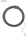
- Figure 2 illustrates a second method of producing a tubular article from material of an embodiment of the invention.
- the method is the same as that for the tube 12 of Figure 1 except that the wrapping is not carried out in a helical fashion but is effected by circumferential wrapping of a long length of porous_film (such as ePTFE) film 13 about the longitudinal axis of a mandrel 14 to form a tube 15.
- a long length of porous_film such as ePTFE
- Either the longitudinal or transverse direction of the film 13 may be wrapped onto the mandrel 14.
- Circumferential wrapping of long length film 13 such that the film is wrapped directly from the takeoff of a film spool on to the mandrel 14 limits the final tube length to the width of the precursor film 13.
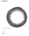
- the tubes 12 and 15 of Figures 1 to 3 may be provided with a porous base tube 17 as shown in Figure 4.
- the base tube 17 forms a luminal surface.
- the base tube 17 is applied to the mandrel before one or more layers of film, such as porous ePTFE is or are wrapped around the exterior surface of the base tube 17.
- the finished tube may be constituted by layers comprising a combination of both helical and circumferential wrapping.
- inventive article such as a tube as described with reference to Figures 1 to 4
- inventive article may be constituted by a single sheet of porous film it may be preferred that the articles of the invention, including the tubes of Figures 1 to 4, are constituted by multiple sheets of porous film.
- the multi-layered film assembly is heated at sufficient temperature and a long enough time to ensure bonding of the layers. Insufficient heating may result in a tube prone to delamination.
- the number of film layers may be varied in order to optimise tube wall thickness and tube flexibility.
- the diameter of the mandrel may be varied to produce a tube of a desired inner diameter.
- FIG. 1 to 4 are in the form of tubes, it will be readily apparent to those of skill in the art that articles in accordance with embodiments of the present invention may take forms other than tubular.
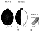
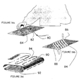
- a pouch 18 of porous ePTFE may be formed as shown in Figure 5.
- the porous material may form other containers in a variety of shapes, conduits, container liners, membranes or the like which are intended to facilitate the containment during transport or storage of a low temperature, low surface energy fluid such as cryogenic liquid.
- a membrane suitable for forming the pouch 18 as shown in Figure 5 multiple layers of film are wrapped onto a large diameter mandrel, the ends restrained and the assembly placed in an oven in order to bond the layers together using the films and process temperatures described in the examples below.
- the large diameter tube thus produced is slit longitudinally to provide a flat membrane and the resultant membrane formed into a pouch 18, the multi-layered nature of the membrane 19 being evident from Figures 5b and 5c.
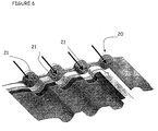
- a membrane may be formed into other shapes and forms, such as a flat construction 20 with predetermined conduits 21, as illustrated in Figure 6.
- Figures 7 and 8 illustrate a particular embodiment of the present invention in which a conduit in the form of a tube of porous ePTFE capable of containing a cryogenic fluid such as liquid nitrogen, argon, or liquid air and which will allow the gaseous phase of the fluid to permeate to the exterior of the tube is incorporated in a protective garment such as may be worn by a firefighter or the like.
- a cryogenic fluid such as liquid nitrogen, argon, or liquid air
- Figures 7 and 8 are respectively front and back views of a fire-fighting garment 22.
- the garment 22 incorporates a container 23 for containing liquid nitrogen or liquid air (in this example reference will be made to liquid nitrogen) connected to distribution tubes 24 forming a network of tubes for distributing the liquid nitrogen throughout the garment.
- the system of tubes 24 is located between an insulation layer of the garment and an inner lining.
- the container 23 for holding liquid nitrogen comprises an insulated pressure vessel for holding the liquid nitrogen and a valve mechanism 25 controlled by a valve-trigger 26 for allowing passage of liquid nitrogen into the tubes 24.
- the tubes 24 are connected to the valve-trigger mechanism 26 via a restriction orifice, the restriction of which determines the cooling rate.
- the valve-trigger 26 allows the flow to be turned on and off or to be regulated.
- the liquid nitrogen container 23 contains a 0.5 kg charge which lasts for approximately 35 minutes at full gas delivery. Over this time period, 0.5 kg of liquid nitrogen provides approximately 100 watts of cooling.
- the container 23 is of a suitable shape to be located in a pocket inside or more preferably outside the garment where it may be manually controlled by the wearer.
- the nitrogen permeates through the wall of the tubes to emerge from the outer surface of the tubes in gaseous phase.
- the evaporative transition of the nitrogen from the liquid to gaseous phase provides a cooling effect at the outer tube surface which is transmitted to the wearer of the garment.
- the flow is regulated by an electronic control means responsive to temperatures within the garment, so that the garment temperature is maintained thermostatically to a constant value.
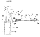
- a liquid nitrogen leak pressure test was developed to measure the pressure at which liquid nitrogen permeates through a cryogen tube wall. Liquid nitrogen is added to the lumen of tested tubes and pressurised. The tube is examined to ensure the permeation of gaseous nitrogen through the tube wall. The pressure at which liquid nitrogen leaks through the walls of the tube is noted and recorded. This pressure corresponds to the pressure at which the mass flow rate of liquid nitrogen flowing through the wall in the radial direction exceeds the mass evaporation rate of the liquid at the outer wall surface.
- a schematic representation of the test apparatus appears in Figure 9. A 0.5 Litre Dewar flask (Cryo Jem. Cryomedical Instruments Ltd.
- Air pressure is applied to the top of the liquid nitrogen reservoir.
- the pressure is regulated via a precision regulator (Moore. Model 41-100) 32.
- a pressure monitoring tap is included in the line entering the flask for safety reasons.
- the Dewar flask 30 inlet pressure is measured with a multi-port pressure transducer (Heise, model PM. Newtown.CT) or gauge 33.
- Liquid nitrogen is forced out of the flask through a 0.062 inch (1.58 mm) inner diameter stainless steel dip tube 34 that extends from near the bottom of the flask to an opening in the flask lid 31.
- a lever valve 35 at the head controls the exit flow.
- the dip tube 34 extends beyond this valve 35, enclosed in a larger plastic conduit 36.
- Threaded fittings 37 are attached to the larger conduit 36.
- Another pressure monitoring tap is included in the line in order to measure the inlet pressure to the tested tube (using the same pressure monitor as described above or guage 38).
- a standard barb fitting 40 is screwe
- the tube 39 to be tested is cut to a length of 180 mm.
- the test length is about 135 mm since portions of the ends are attached over fittings 40, 42.
- One end of the tube 39 is attached over the barb fitting 40 and secured by wrapping silver plated copper wire 41 tightly around the outside of the tube 39.
- the other end of the tube 39 is fitted with a barb fitting 42 and secured in the same manner.
- the outlet of this barb 42 fitting is fitted with a 0.50 inch (12.7 mm) long PTFE cylindrical plug 43.
- the plug 43 has a 0.062 inch (1.58 mm) diameter, 0.075 inch (1.90 mm) long hole 44 drilled through its centre, which is counter-bored to 0.125 inch (3.18 mm) diameter for a length of 0.425 inch (10.8 mm).
- outlet orifice diameter and dip tube inside diameter are specified to match. These are the smallest flow restrictions in the line exiting the flask. This choice of outlet orifice 44 and dip tube inside diameter enables a sufficient test duration before exhausting the liquid nitrogen from the flask. Venting the outlet to atmosphere enhances the flow of liquid nitrogen into the tube to be tested.
- the tube 39 is positioned horizontally.
- the test is performed under a hood at ambient conditions: room temperature is 19.6°C, relative humidity is about 46% and in essentially still air.
- the nitrogen exiting the end of the tube is directed outside of the hood in order not to disturb the air flow under the hood.
- the tube 39 is tested in the following manner.
- the Dewar flask lever valve 35 is opened.
- the pressure regulator 32 is adjusted until liquid nitrogen exits the orifice 44 at the end of the test sample tube.
- the discharge of liquid nitrogen is readily confirmed by placing an expanded PTFE membrane in the path of the exiting nitrogen and noting wetting of the membrane. All fittings and connection are examined to ensure that no leaks are present.
- the tube 39 is then examined for gaseous permeation of nitrogen through its wall, along the length of the tube as evidenced by a plume of condensed water vapour in the vicinity of the tube.
- the applied pressure is adjusted until such a steady plume is observed. A steady plume indicates both gas permeation and that the air is still in the test environment.
- the plume as described demonstrates that gaseous nitrogen is exiting along the length of the tube 39, which is indicative of distributed evaporative cooling. Note that the pressure increase in the Dewar flask 30 resulting from the evaporation of the nitrogen alone may be sufficient to pressurise the tube 39.
- the tube under test is allowed to chill for a period of 30 seconds prior to further pressure adjustment.
- the pressure is increased until the first droplet of liquid nitrogen appears on the outer surface of the tested tube 39.
- the pressure regulator 32 is slowly and slightly opened and closed to ensure that this is the pressure corresponding to the formation of the first stable droplet.
- a stable droplet is one that under constant pressure, remains about the same size during testing for at least 5 seconds, without dripping. By decreasing the pressure the droplet will evaporate. With increasing pressure, the droplet size increases past stability until liquid is first dripping rapidly and then running out of the tube wall.
- the pressure measured at the entrance to the tested tube 39 is recorded. This average of three pressure readings, taken at intervals of at least 20 seconds as measured with the pressure gauge 38 is recorded as the liquid nitrogen leak pressure in Table 2.
- Venting the tube 39 to atmosphere via the use of the plug 43 with the 0.062 inch (1.58 mm) orifice 44 is important to achieve the distribution of liquid nitrogen across the length of the tube 39.
- Tubes in accordance with the preferred embodiments of the present invention permeate the most gas when liquid cryogen is present on the interior surface. Boiling of the liquid inside the tube appears to enhance gaseous permeation.
- test was developed specifically for testing tubes, the same principles may be applied to create a test for the examination of the properties of other shapes of materials.
- the important elements of the test include: controlled application of pressure and ability to measure the pressure required to force a mass of liquid nitrogen sufficient to form a stable drop of liquid on the outside wall of the test article, through the thickness of the article while the internal surface of the article is in contact with liquid.
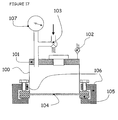
- a liquid nitrogen leak pressure test can also be performed on a flat sheet article of the present invention.
- a schematic representation of the test apparatus appears in Figure 17.
- a cylinder 100 is equipped with a fill lid 101 and pressure relief valve 102, a pressurization means 103,and a pressure measurement guage107.
- the flat sheet article 104 is attached to the bottom of the cylinder by a ring 105 and clamps 106.
- the cylinder is filled with liquid nitrogen to cover the sheet sample and the lid 101 is screwed on slowly to allow excess nitrogen to boil off.
- Air pressure is applied to the top of the cylinder and is regulated and monitored as previously described for the liquid nitrogen leak pressure testing of tubes.
- the test is also conducted as previously described. During these tests the article under test must be exposed to the same environmental temperature and humidity conditions as stated previously, allowing stable convection and evaporation conditions at the outer surface of the test article.
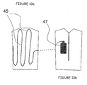
- a tube 45 is placed inside a vest and connected at one end to a Dewar flask 47 containing liquid nitrogen as indicated in Figures10a and 10b. The other end of the tube 45 is vented to atmosphere.
- a subject wears the vest over a shirt and wears a fire jacket over the vest. The subject walks on a treadmill set at a rate of 3 miles (4.8 km)/hour at a 5% incline. The test is conducted in a room at ambient conditions: room temperature is 21°C, relative humidity is about 41% and essentially still air.
- the cooling system is worn over underwear and under a heavy, insulated jacket, minimum weight 1.5 kg, during test.
- the tubes are mounted to barbed luer fittings and secured with clamps and tested intact.
- the values of three samples per tube are obtained and averaged for the isopropanol (IPA) bubble point and the thickness measurements.
- IPA isopropanol
- One Gurley air permeability measurement is made per tube.
- IBP isopropanol bubble points
- the air permeability measurement is determined using a Gurley Densometer (Model 4110, W. & L.E. Gurley, Troy, NY) fitted with an adapter plate that allows the testing of a length of tubing. A one foot length of tubing is tested, unless otherwise noted.
- the average internal surface area is calculated from the measurements utilising a Ram Optical Instrument (OMIS II 6 x12, Ram Optical Instrumentation Inc., 15192 Triton Lane, Huntington Beach, CA).
- the Gurley Densometer measures the time it takes for 100 cc of air to pass through the wall of the tube under 4.88 inches (12.40 cm) of water head of pressure.
- the air permeability value is calculated as the inverse of the product of the Gurley number and the internal surface area of the tube expressed in units of cc/min cm 2 .
- the wall thickness and inner diameter of the tube are measured using the same OMIS II optical system.
- Bubble point of films is measured according to the procedures of ASTM F31 6-86.
- the film is wetted with isopropanol or methanol, as noted in the examples.
- Film thickness is measured with a snap gauge (Mitutoyo, model 2804-10, Japan).
- the tube is placed in a 1.5 L Dewar flask filled with liquid nitrogen for a period of 30 seconds.
- the tube is removed and quickly wrapped around a hollow steel cylinder having an outer diameter of 1.5 inch (38.1 mm) and a wall thickness of 0.05 inch (1.27 mm).
- the tube is visually examined for evidence of fracture, to determine if the wrapping had compromised the ability of the tube to hold liquid (liquid argon is used in testing the tubes of Example 8).
- a tube that does not fracture during this test is considered to be flexible.
- Expanded PTFE film is obtained in a 42 inch (106.7 mm) width possessing a thickness of 0.0035 inch (0.09 mm), a Gurley number of 39.5 seconds and an isopropanol bubble point of 48.5 psi (0.334 MPa). All measurements are made in accordance with the procedures previously described, unless otherwise indicated.
- the film is circumferentially wrapped around a 0.25 inch (6.4 mm) stainless steel mandrel such that the width of the film becomes the length of the resultant tube as depicted in Figure 2. Twelve layers of film are wrapped around the mandrel.
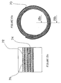
- the cross-sectional geometry of the layered construction is spiral-shaped as indicated in Figures 3 and 4. The construction parameters for this and other examples appear in Table 1.
- the ends of the layered film construction are restrained by suitable means to prevent shrinkage in the longitudinal direction of the construction (the longitudinal axis of the mandrel) during subsequent heat treatment.
- the restrained construction is submerged in a 365°C molten salt bath oven for 1.5 minutes in order to bond the ePTFE layers and impart dimensional stability to the tube.
- the tube is allowed to cool then washed in ambient temperature water to remove residual salt.
- the clamps are removed and the tube is removed over the end of the mandrel.
- the tube is measured for inner diameter, wall thickness, Gurley number, and IBP in accordance with the techniques previously described.
- the tube is also tested to determine if it serves as an effective conduit for the transport of liquid nitrogen while allowing the passage of gaseous nitrogen through the wall. Further tests are performed to determine the pressure at which the tube passes liquid nitrogen through the wall. The test results for this and other examples appear in Table 2.
- the tube controls the passage of gaseous nitrogen and inhibits the passage of liquid nitrogen at an average LNLP of 6.0 psi (0.041 MPa).
- the individual pressure readings are 5.8 psi (0.040 MPa), 5.8 psi (0.040 MPa) and 6.4 psi (0.044 MPa).
- a portion of the tube is dipped in liquid nitrogen for 30 seconds then quickly wrapped around the outside of a 1.5 inch (38.1 mm) outer diameter, 0.05 inch (1.27 mm) wall thickness steel hollow cylinder to demonstrate the flexibility of the cold tube.
- the tube does not fracture under these conditions.
- a scanning electron micrograph of the tube cross-section (a view taken transverse from the longitudinal axis of the tube) appears in Figure 11.
- a 10 micrometer reference bar appears at the bottom right of the figure.
- This tube is tested as a cooling garment tube as described above. A 36 inch length of this tube is used to create a cryogenic cooling garment as illustrated in Figure 10. The subject walks on the treadmill while wearing the garment. The tube and garment perform satisfactorily. The tube does not leak liquid nitrogen and permeates enough gaseous nitrogen to keep the subject cool throughout the test.
- This tube is also tested to measure the flow rate of gaseous nitrogen permeating through the wall.
- the test set up described for measuring the liquid nitrogen leak pressure is slightly modified from that of Figure 9, and is illustrated in Figure 12.
- the change consists of enclosing the tube 50 inside a cylindrical enclosure 52 of about 1.5 inch (38.1 mm) inner diameter such that the tube 50 still vents to atmosphere. All of the gas permeating through the wall of the tube 50, however, is contained within the enclosure 52.
- An air flow meter (range 2-20 standard cubic feet per hour (scfh) [0.06-0.6 standard cubic meters per hour (scmh)], King Instrument Co.) 54 is connected to a port in the wall of the enclosure 52. The flow rate of the permeating gas is measured.
- a thin longitudinally expanded PTFE tube is obtained possessing a wall thickness of 0.119 mm, an inner diameter of 3.0 mm, and an IBP of 1.0 psi (0.007 MPa). This tube is snugly slipped over the 0.25 inch (6.4 mm) diameter mandrel.
- the ePTFE film of Example 1 is then applied over the thin ePTFE base tube in the same manner as the film is applied to the mandrel in Example 1.
- the construction is restrained then heated in a 365°C molten salt bath for 2 minutes, cooled, washed in ambient water, then removed from the mandrel. In all examples, the presence of a base tube results in easier removal of the tube from the mandrel.
- the tube is tested as described in Example 1 and the results appear in Table 2.
- the tube controls the passage of gaseous nitrogen and inhibits the passage of liquid nitrogen at an average LNLP of 0.4 psi (0.003 MPa).
- the three individual pressure readings are all 0.4 psi.
- Another portion of the same tube is tested. All three liquid nitrogen leak pressures are 0.7 psi (0.005 MPa).
- a portion of the tube is dipped in liquid nitrogen for 30 seconds then quickly wrapped around the outside of a 1.5 inch (38.1 mm) outer diameter, 0.05 inch (1.27 mm) wall thickness steel hollow cylinder to demonstrate the flexibility of the cold tube. The tube does not fracture under these conditions.
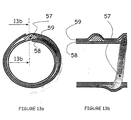
- Example 2 Another tube is created in this same manner as Example 2 except that 1/8 inch (3.18 mm) PTFE dry paste-extruded beading is applied in a helical fashion to the base tube prior to the application of the film.
- the beading is applied with a 3 ⁇ 4 inch (19.05 mm) lead.
- the purpose of the beading is to impart greater compression resistance and kink resistance to the final tube upon bending.
- FIG. 13a and 13b An example of a tube including such beading is illustrated in Figures 13a and 13b, although in the illustrated tube the beading 57 is provided between two wrapped films 58 and 59, rather than between a base tube and a wrapped film.
- the tube is tested as described in Example 1 and the results appear in Table 2.
- the tube controls the passage of gaseous nitrogen and inhibits the passage of liquid nitrogen at an average LNLP of 6.6 psi (0.046 MPa).
- the individual pressure readings are all 6.6 psi (0.046 MPa).
- a portion of the tube is dipped in liquid nitrogen for 30 seconds then quickly wrapped around the outside of a 1.5 inch (38.1 mm) outer diameter, 0.05 inch (1.27 mm) wall thickness steel hollow cylinder to demonstrate the flexibility of the cold tube. The tube does not fracture under these conditions.
- a tube is made using the film of Example 1.
- the film is slit to provide a width of 0.875-inch (22.2 mm) and is helically applied over the base tube of Example 2.
- the film is applied with approximately 50% overlap to provide about 18 layers of film over the base tube.
- the restrained construction is placed in a 366°C molten salt bath for 2 minutes.
- the tube enables the passage of gaseous nitrogen and inhibits the passage of liquid nitrogen at an average LNLP of 10.9 psi (0.075 MPa).
- the individual pressure readings are 9.0 psi (0.062 MPa), 9.0 psi (0.062 MPa) and 14.8 psi (0.102 MPa).
- a portion of the tube is dipped in liquid nitrogen for 30 seconds then quickly wrapped around the outside of a 1.5 inch (38.1 mm) outer diameter, 0.05 inch (1.27 mm) wall thickness steel hollow cylinder to demonstrate the flexibility of the cold tube.
- the tube does not fracture under these conditions.
- a tube is made in accordance with the same steps and materials as described in Example I and Table 1 except for the differences noted as follows.
- Example 1 The film of Example 1 is circumferentially wrapped around a 0.25 inch (6.4 mm) stainless steel mandrel such that the length of the film becomes the length of the resultant tube. As in Example 1, twelve layers of film are wrapped around the mandrel. This method of construction enables the creation of a length of tube that is not limited to the width of the film. The restrained construction is submerged in a 366°C molten salt bath oven for 1.5 minutes in order to bond the ePTFE layers and impart dimensional stability to the tube.
- the tube controls the passage of gaseous nitrogen and inhibits the passage of liquid nitrogen at an average LNLP of 8.2 psi (0.057 MPa).
- the individual pressure readings are 8.2 psi (0.057 MPa), 8.2 psi (0.057 MPa) and 8.3 psi (0.057 MPa).
- a portion of the tube is dipped in liquid nitrogen for 30 seconds then quickly wrapped around the outside of a 1.5 inch (38.1 mm) outer diameter, 0.05 inch (1.27 mm) wall thickness steel hollow cylinder to demonstrate the flexibility of the cold tube.
- the tube does not fracture under these conditions.
- a tube is made from three components, combining the construction methods of Examples 1 and 4. That is, a base tube is placed over a 4.0 mm outer diameter mandrel, followed by circumferentially wrapping a film over the base tube, and finally wrapping yet another film helically atop the circumferential layers.
- the base tube is a longitudinally expanded PTFE tube possessing a wall thickness of about 0.410 mm, an inner diameter of 3.9 mm, and an IBP of 1.1 psi (0.008 MPa).
- the circumferentially wrapped film is an expanded PTFE film approximately 0.0017 inch (0.04 mm) thick, having an IBP of about 29.1 psi (0.201 MPa) and a Gurley number of about 17.7 sec. Eight layers of this film are applied such that the transverse direction (width) of the film is oriented in the longitudinal direction of the mandrel.
- This film is a fluorinated ethylene propylene-coated porous ePTFE film.
- This film is made by a process that comprises the steps of:
- This film has an MBP of 1.7 psi (0.012 MPa) and a thickness of 0.0004 inch (0.01 mm).
- the MBP is measured in the same manner as is IBP for film, except that methanol is substituted for isopropanol.
- This film is slit to a 0.5 inch (12.7 mm) width and then applied helically in multiple traverse passes up and down the length of the mandrel at angles 15° off perpendicular in order to apply 48 layers.
- the restrained construction is placed in a convection oven set at 380°C for 4.9 minutes in order to bond the ePTFE layers and impart dimensional stability to the tube.
- the tube controls the passage of gaseous nitrogen and inhibits the passage of liquid nitrogen at an average LNLP of 0.4 psi (0.003 MPa).
- the individual pressure readings are 0.3 psi (0.002 MPa), 0.3 psi (0.002 MPa) and 0.4 psi (0.003 MPa).
- the length of sample used for the isopropanol bubble point and Gurley air permeability testing is 6.0 inch (15.2 cm).
- a portion of the tube is dipped in liquid nitrogen for 30 seconds then quickly wrapped around the outside of a 1.5 inch (38.1 mm) outer diameter, 0.05 inch (1.27 mm) wall thickness steel hollow cylinder to demonstrate the flexibility of the cold tube.
- the tube does not fracture under these conditions.
- This tube is tested as a cooling garment tube as described above.
- a 43.25 inch (109.8 cm) length of this tube is used to create a cryogenic cooling garment.
- the subject walks on the treadmill while wearing the garment.
- the tube and garment perform satisfactorily.
- the tube does not leak liquid nitrogen and permeates enough gaseous nitrogen to keep the subject cool throughout the test.
- a commercially available rigid ceramic tube was obtained (FERRO Ceramic WFAO-NAJADE (800), Rochester, NY) and tested.
- the tube dimensions are measured using a digital calliper.
- the inner and outer diameters are 14.8 mm and 22.1 mm, respectively.
- the tube is tested for LNLP as described above. The test cannot be performed as required because the tube leaks prior to increasing the pressure enough to enable liquid nitrogen to exit the downstream orifice. Therefore, a value for LNLP cannot be obtained.
- a plume of gaseous nitrogen along the length of the tube, absent liquid nitrogen leakage through the exterior surface, does result at low pressures, namely at 0.2 psi (0.001 MPa).
- Two tubes are made in accordance with the process described in Example 1, except as noted in Table 1.
- the tubes are made with a different number of layers and placed in a molten salt bath set at a different temperature, for a different period of time as compared to the tube of Example 1.
- the tubes are tested for leak pressure in the manner described above except that argon is used as the cryogenic liquid instead of nitrogen. The results appear in Table 2.
- the length of samples used for the isopropanol bubble point and Gurley air permeability testing is 4.8 inch (12.2 cm) and 5.7 inch (14.5 cm) for Examples 8a and 8b, respectively.
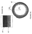
- Figures 14a and 14b illustrate a tube 60 which has been formed by wrapping two sheets 62, 64 of different material around a mandrel.
- Figures 15a and 15b illustrate a tube 70 which has been formed by wrapping a sheet of material 72 around a mandrel.
- the sheet of material 72 is comprised of two materials 74, 76 bonded together, Either or both materials 74, 76 may be adhesive materials.
- Tubes may also be constructed from two or more sheet materials wrapped together around a mandrel. These sheet materials may or may not be bonded together.
- tubes formed in accordance with embodiments of the invention may be used in a wide variety of transport, storage and cooling applications, and a number of possible cooling arrangements are illustrated in Figures 16a, 16b and 16c.
- a tube 80 is shown passing around an individual component 82 mounted on a PCB 84.
- a tube 84 may be arranged to pass around a PCB 86 carrying a number of components 88.
- Figure 16c illustrates a sheet 90, similar to that shown in Figure 6, wrapped around a PCB 92, with conduits 94 formed between appropriate membrane sheets.
- liquid nitrogen, liquid air, or another cryogenic fluid is passed through the tubes in liquid form, the tubes providing cooling by conduction from the "cold" tubes and by convection by the cold gas evaporating at or from the walls of the tubes.
- Cooling arrangements may be provided for use by workers experiencing elevated temperatures in the course of their work, such as fire-fighters, miners working deep underground, operators in steelworks, racing car drivers and the like. Such cooling arrangements may also be of assistance to workers who must wear heavy or warm protective clothing. The consequential flow of gaseous fluid around the wearer's body may also assist in preventing or minimising the build-up of perspiration beneath the wearer's clothes, which may be waterproof or of a construction or arrangement which limits circulation of air.
- the arrangement may utilise liquid air and an arrangement for ensuring a supply of air reaches the wearer and thus provides a supply of cool air for breathing.
- Such cooling arrangements may also be of assistance in medical or veterinary applications, for example where it is useful for a patient's body, or part of a patient's body, to be cooled.
- cooling sheets or enclosures may be utilised to facilitate storage of foodstuffs and other temperature sensitive supplies.
- Articles may be produced in accordance with the present invention with a wide variety of possible designs and properties to suit particular applications.
- specific design modifications that may be contemplated within the scope of the present invention include: providing a conduit that has various permeabilities along its length (for instance, regions ranging from permitting no liquid entry into the material to regions permitting liquid leakage through the exterior surface of the material); having conduits that have various permeabilities around their circumference, so that gas leakage occurs only at pre-determined places around the circumference; having modified segments along the conduit (e.g., being wider or narrower or having modified shapes, etc.) to provide specific delivery properties; etc.
Landscapes
- Engineering & Computer Science (AREA)
- Mechanical Engineering (AREA)
- General Engineering & Computer Science (AREA)
- Environmental & Geological Engineering (AREA)
- Health & Medical Sciences (AREA)
- General Health & Medical Sciences (AREA)
- Physical Education & Sports Medicine (AREA)
- Textile Engineering (AREA)
- Laminated Bodies (AREA)
- Filling Or Discharging Of Gas Storage Vessels (AREA)
- Rigid Pipes And Flexible Pipes (AREA)
- Thermotherapy And Cooling Therapy Devices (AREA)
Applications Claiming Priority (3)
| Application Number | Priority Date | Filing Date | Title |
|---|---|---|---|
| US327808 | 1999-06-08 | ||
| US09/327,808 US6427451B2 (en) | 1999-06-08 | 1999-06-08 | Material for the controlled vaporization of a liquid cryogen |
| PCT/US2000/014876 WO2000075558A2 (en) | 1999-06-08 | 2000-05-30 | Material for the controlled vaporization of a liquid cryogen |
Publications (2)
| Publication Number | Publication Date |
|---|---|
| EP1192388A2 EP1192388A2 (en) | 2002-04-03 |
| EP1192388B1 true EP1192388B1 (en) | 2005-10-26 |
Family
ID=23278155
Family Applications (1)
| Application Number | Title | Priority Date | Filing Date |
|---|---|---|---|
| EP00939416A Expired - Lifetime EP1192388B1 (en) | 1999-06-08 | 2000-05-30 | Material for the controlled vaporization of a liquid cryogen |
Country Status (7)
| Country | Link |
|---|---|
| US (7) | US6427451B2 (enExample) |
| EP (1) | EP1192388B1 (enExample) |
| JP (1) | JP2003501603A (enExample) |
| AU (1) | AU5450500A (enExample) |
| CA (1) | CA2371236C (enExample) |
| DE (1) | DE60023499T2 (enExample) |
| WO (1) | WO2000075558A2 (enExample) |
Families Citing this family (27)
| Publication number | Priority date | Publication date | Assignee | Title |
|---|---|---|---|---|
| US7327387B2 (en) * | 2000-02-21 | 2008-02-05 | Fujifilm Corporation | Image pick-up information transmitting system and remote control method for an information transmitting system |
| GB0004174D0 (en) * | 2000-02-22 | 2000-04-12 | Gore & Ass | Cryogenic fluid transfer tube |
| US7266965B2 (en) * | 2000-06-21 | 2007-09-11 | Blackstone Ralf W | Air cooling device |
| US20080066484A1 (en) * | 2001-06-21 | 2008-03-20 | Blackstone Ralf W | Air cooling device |
| US20090044932A1 (en) * | 2001-06-21 | 2009-02-19 | Blackstone Ralf W | Air cooling device |
| US20040024392A1 (en) * | 2002-08-05 | 2004-02-05 | Lewis James D. | Apparatus and method for cryosurgery |
| US7010931B2 (en) * | 2002-09-20 | 2006-03-14 | Clemie Lee | Nanoclimate clothing and apparel |
| GB2394528A (en) * | 2002-10-22 | 2004-04-28 | Gore Enterprise Holdings Inc | Cryogenic pressure building device |
| US6737158B1 (en) * | 2002-10-30 | 2004-05-18 | Gore Enterprise Holdings, Inc. | Porous polymeric membrane toughened composites |
| DE10315607B4 (de) * | 2003-05-13 | 2005-12-08 | Dräger Safety AG & Co. KGaA | Belüftungssystem für Schutzbekleidung |
| US8499367B2 (en) * | 2004-07-02 | 2013-08-06 | Createc Consulting, Llc | Cooling garment having phase change material in its extremity portions |
| US20060064147A1 (en) * | 2004-07-02 | 2006-03-23 | Almqvist Hans O | Cooling garment having phase change material in its extremity portions |
| US7308803B2 (en) * | 2004-07-21 | 2007-12-18 | Owens Corning Intellectual Capital, Llc | Insulation system with condensate wicking for vertical applications |
| US20060036130A1 (en) * | 2004-08-12 | 2006-02-16 | International Polymer Engineering, Inc. | Endoscopic working channel and method of making same |
| US7716850B2 (en) * | 2006-05-03 | 2010-05-18 | Georgia-Pacific Consumer Products Lp | Energy-efficient yankee dryer hood system |
| KR101186761B1 (ko) | 2006-08-28 | 2012-10-08 | 에어 프로덕츠 앤드 케미칼스, 인코오포레이티드 | 극저온 액체 분사용 분사 장치 및 이 장치와 관련된 분사 방법 |
| WO2008053227A1 (en) * | 2006-11-01 | 2008-05-08 | Remploy Limited | Material cooling system |
| US20100256445A1 (en) * | 2006-12-07 | 2010-10-07 | International Polymer Engineering, Inc. | Endoscopic Working Channel and Method of Making Same |
| US20080139887A1 (en) * | 2006-12-07 | 2008-06-12 | International Polymer Engineering, Inc. | Endoscopic working channel and method of making same |
| WO2009023756A2 (en) * | 2007-08-15 | 2009-02-19 | Johnson Controls Technology Company | Vapor compression system and frost control |
| GB2458097A (en) * | 2007-10-30 | 2009-09-09 | Wolfgang Obert | Cooling using cryogenic liquids |
| US10337761B2 (en) | 2007-12-21 | 2019-07-02 | Ralf W. Blackstone | Microenvironmental cooling system |
| US20090255274A1 (en) * | 2008-04-14 | 2009-10-15 | Ungar Eugene K | System and method for recharging a high pressure gas storage container by transport of a low pressure cryogenic fluid |
| EP2276966B1 (en) * | 2008-05-16 | 2012-10-17 | Lawrence Livermore National Security, LLC | Cryogenic capable high pressure containers for compact storage of hydrogen onboard vehicles |
| US9308121B2 (en) * | 2011-02-07 | 2016-04-12 | Roger Clemente | Helical air distribution system |
| JP2017503884A (ja) * | 2013-12-19 | 2017-02-02 | ダブリュ.エル.ゴア アンド アソシエイツ,インコーポレイティドW.L. Gore & Associates, Incorporated | 断熱延伸ポリテトラフルオロエチレン物品 |
| TWI546559B (zh) | 2015-05-19 | 2016-08-21 | 長興材料工業股份有限公司 | 增光穿透塗料組合物及由其所形成之塗層 |
Family Cites Families (20)
| Publication number | Priority date | Publication date | Assignee | Title |
|---|---|---|---|---|
| US2969092A (en) * | 1955-10-21 | 1961-01-24 | Herrick L Johnston Inc | Method and apparatus for containing a liquified gas |
| US3206939A (en) * | 1962-12-26 | 1965-09-21 | Union Carbide Corp | Cryogenic fluid transfer system |
| US3295563A (en) * | 1963-12-27 | 1967-01-03 | Gen Dynamics Corp | Method and apparatus for handling cryogenic liquids |
| US3699775A (en) * | 1969-12-11 | 1972-10-24 | Sub Marine Systems Inc | Gas and liquid processing system |
| US3777501A (en) * | 1971-03-12 | 1973-12-11 | Martin Marietta Corp | Capillary insulation |
| GB1458357A (en) * | 1973-02-05 | 1976-12-15 | Marshall D A G | Fire-fighting suit |
| SU474173A1 (ru) * | 1973-05-03 | 1975-11-15 | Всесоюзный научно-исследовательский институт горноспасательного дела | Газотеплозащитный костюм |
| US4082893A (en) * | 1975-12-24 | 1978-04-04 | Sumitomo Electric Industries, Ltd. | Porous polytetrafluoroethylene tubings and process of producing them |
| US4571954A (en) | 1984-12-04 | 1986-02-25 | The United States Of America As Represented By The Secretary Of The Army | Waveguide phase conjugate mirror |
| DE3531407A1 (de) * | 1985-09-03 | 1987-03-12 | Mansour Almassi | Vorrichtung zum wenigstens teilweisen bedecken des menschlichen koerpers |
| US4738119A (en) | 1987-02-09 | 1988-04-19 | Westinghouse Electric Corp. | Integral cooling garment for protection against heat stress |
| US4745760A (en) | 1987-07-21 | 1988-05-24 | Ncr Corporation | Cryogenic fluid transfer conduit |
| US5520682A (en) | 1991-09-06 | 1996-05-28 | Cryomedical Sciences, Inc. | Cryosurgical instrument with vent means and method using same |
| US5400602A (en) | 1993-07-08 | 1995-03-28 | Cryomedical Sciences, Inc. | Cryogenic transport hose |
| US5511542A (en) | 1994-03-31 | 1996-04-30 | Westinghouse Electric Corporation | Lox breathing system with gas permeable-liquid impermeable heat exchange and delivery hose |
| US5533354A (en) * | 1994-09-20 | 1996-07-09 | Texan Corporation | Personal comfort apparatus |
| US5572880A (en) * | 1995-04-21 | 1996-11-12 | Figgie International Inc. | Apparatus for providing a conditioned airflow inside a microenvironment and method |
| EP0797752B1 (fr) * | 1995-10-06 | 2000-02-09 | Manufacture De Vetements Paul Boye S.A. | Procede et dispositif frigorigenes |
| US5946931A (en) | 1998-02-25 | 1999-09-07 | The United States Of America As Represented By The Administrator Of The National Aeronautics And Space Administration | Evaporative cooling membrane device |
| GB2336782A (en) * | 1998-04-30 | 1999-11-03 | Spembly Medical Ltd | Cryosurgical apparatus |
-
1999
- 1999-06-08 US US09/327,808 patent/US6427451B2/en not_active Expired - Lifetime
-
2000
- 2000-05-30 EP EP00939416A patent/EP1192388B1/en not_active Expired - Lifetime
- 2000-05-30 DE DE60023499T patent/DE60023499T2/de not_active Expired - Lifetime
- 2000-05-30 CA CA002371236A patent/CA2371236C/en not_active Expired - Fee Related
- 2000-05-30 AU AU54505/00A patent/AU5450500A/en not_active Abandoned
- 2000-05-30 JP JP2001501798A patent/JP2003501603A/ja active Pending
- 2000-05-30 WO PCT/US2000/014876 patent/WO2000075558A2/en not_active Ceased
-
2002
- 2002-07-11 US US10/193,528 patent/US6622512B1/en not_active Expired - Lifetime
- 2002-07-11 US US10/192,912 patent/US6622493B1/en not_active Expired - Lifetime
- 2002-07-11 US US10/193,440 patent/US6644040B1/en not_active Expired - Lifetime
- 2002-07-11 US US10/193,527 patent/US6526761B1/en not_active Expired - Lifetime
- 2002-07-11 US US10/193,535 patent/US6688128B1/en not_active Expired - Lifetime
- 2002-07-11 US US10/193,436 patent/US6644042B1/en not_active Expired - Lifetime
Also Published As
| Publication number | Publication date |
|---|---|
| WO2000075558A3 (en) | 2002-01-17 |
| US6688128B1 (en) | 2004-02-10 |
| CA2371236A1 (en) | 2000-12-14 |
| CA2371236C (en) | 2007-03-13 |
| US6622493B1 (en) | 2003-09-23 |
| US6427451B2 (en) | 2002-08-06 |
| JP2003501603A (ja) | 2003-01-14 |
| US6644042B1 (en) | 2003-11-11 |
| US20020014080A1 (en) | 2002-02-07 |
| US6622512B1 (en) | 2003-09-23 |
| EP1192388A2 (en) | 2002-04-03 |
| US6644040B1 (en) | 2003-11-11 |
| US6526761B1 (en) | 2003-03-04 |
| DE60023499T2 (de) | 2006-07-20 |
| DE60023499D1 (de) | 2005-12-01 |
| WO2000075558A2 (en) | 2000-12-14 |
| AU5450500A (en) | 2000-12-28 |
Similar Documents
| Publication | Publication Date | Title |
|---|---|---|
| EP1192388B1 (en) | Material for the controlled vaporization of a liquid cryogen | |
| CA2493726A1 (en) | Improved apparatus and method for cryosurgery | |
| RU2546483C2 (ru) | Слоистая структура, обеспечивающая адаптивную тепловую изоляцию | |
| US20030106325A1 (en) | Cryogenic fluid transfer tube | |
| US20090036971A1 (en) | Ptfe layers and methods of manufacturing | |
| US6513521B1 (en) | Cryogenic mixed gas single phase storage and delivery | |
| EP2193307B1 (en) | Apparatus and method for providing condensation-and frost-free surfaces on cryogenic components | |
| KR20150034247A (ko) | 적응적 단열을 제공하는 라미나 구조체용 엔벨로프 | |
| KR20150034286A (ko) | 적응적 단열을 제공하는 라미나 구조체용 엔벨로프 | |
| CA2408755A1 (en) | Cryogenic fluid transfer and storage | |
| WO2002055924A1 (en) | Cryogenic liquid delivery system with microporous phase separator | |
| KR20200070059A (ko) | 액화 공기를 이용하는 착용형 냉각장치 및 호흡장치 | |
| WO2004038280A1 (en) | Cryogenic pressure-building device comprising a porous membrane | |
| AU2002225133A1 (en) | Cryogenic liquid delivery system with microporous phase separator | |
| WO1996012521A1 (en) | Heat exchange in a mixed gas delivery system for body cooling and gas conditioning |
Legal Events
| Date | Code | Title | Description |
|---|---|---|---|
| PUAI | Public reference made under article 153(3) epc to a published international application that has entered the european phase |
Free format text: ORIGINAL CODE: 0009012 |
|
| 17P | Request for examination filed |
Effective date: 20020108 |
|
| AK | Designated contracting states |
Kind code of ref document: A2 Designated state(s): AT BE CH CY DE DK ES FI FR GB GR IE IT LI LU MC NL PT SE |
|
| AX | Request for extension of the european patent |
Free format text: AL;LT;LV;MK;RO;SI |
|
| 17Q | First examination report despatched |
Effective date: 20030701 |
|
| RBV | Designated contracting states (corrected) |
Designated state(s): CH DE FR GB IT LI SE |
|
| GRAP | Despatch of communication of intention to grant a patent |
Free format text: ORIGINAL CODE: EPIDOSNIGR1 |
|
| GRAS | Grant fee paid |
Free format text: ORIGINAL CODE: EPIDOSNIGR3 |
|
| GRAA | (expected) grant |
Free format text: ORIGINAL CODE: 0009210 |
|
| AK | Designated contracting states |
Kind code of ref document: B1 Designated state(s): CH DE FR GB IT LI SE |
|
| PG25 | Lapsed in a contracting state [announced via postgrant information from national office to epo] |
Ref country code: CH Free format text: LAPSE BECAUSE OF FAILURE TO SUBMIT A TRANSLATION OF THE DESCRIPTION OR TO PAY THE FEE WITHIN THE PRESCRIBED TIME-LIMIT Effective date: 20051026 Ref country code: LI Free format text: LAPSE BECAUSE OF FAILURE TO SUBMIT A TRANSLATION OF THE DESCRIPTION OR TO PAY THE FEE WITHIN THE PRESCRIBED TIME-LIMIT Effective date: 20051026 |
|
| REG | Reference to a national code |
Ref country code: GB Ref legal event code: FG4D |
|
| REG | Reference to a national code |
Ref country code: CH Ref legal event code: EP |
|
| REF | Corresponds to: |
Ref document number: 60023499 Country of ref document: DE Date of ref document: 20051201 Kind code of ref document: P |
|
| REG | Reference to a national code |
Ref country code: SE Ref legal event code: TRGR |
|
| REG | Reference to a national code |
Ref country code: CH Ref legal event code: PL |
|
| ET | Fr: translation filed | ||
| PLBE | No opposition filed within time limit |
Free format text: ORIGINAL CODE: 0009261 |
|
| STAA | Information on the status of an ep patent application or granted ep patent |
Free format text: STATUS: NO OPPOSITION FILED WITHIN TIME LIMIT |
|
| 26N | No opposition filed |
Effective date: 20060727 |
|
| REG | Reference to a national code |
Ref country code: FR Ref legal event code: PLFP Year of fee payment: 16 |
|
| REG | Reference to a national code |
Ref country code: GB Ref legal event code: 732E Free format text: REGISTERED BETWEEN 20150723 AND 20150729 |
|
| REG | Reference to a national code |
Ref country code: DE Ref legal event code: R082 Ref document number: 60023499 Country of ref document: DE Representative=s name: KLUNKER, SCHMITT-NILSON, HIRSCH, DE Ref country code: DE Ref legal event code: R081 Ref document number: 60023499 Country of ref document: DE Owner name: W.L. GORE & ASSOCIATES (UK) LTD., GB Free format text: FORMER OWNERS: GORE ENTERPRISE HOLDINGS, INC., NEWARK, DEL., US; W.L. GORE & ASSOCIATES (UK) LTD., WEST LOTHIAN, GB Ref country code: DE Ref legal event code: R081 Ref document number: 60023499 Country of ref document: DE Owner name: W.L. GORE & ASSOCIATES, INC., NEWARK, US Free format text: FORMER OWNERS: GORE ENTERPRISE HOLDINGS, INC., NEWARK, DEL., US; W.L. GORE & ASSOCIATES (UK) LTD., WEST LOTHIAN, GB Ref country code: DE Ref legal event code: R082 Ref document number: 60023499 Country of ref document: DE Representative=s name: KLUNKER IP PATENTANWAELTE PARTG MBB, DE |
|
| REG | Reference to a national code |
Ref country code: FR Ref legal event code: PLFP Year of fee payment: 17 |
|
| REG | Reference to a national code |
Ref country code: FR Ref legal event code: TP Owner name: W.L. GORE & ASSOCIATES, INC., US Effective date: 20160510 |
|
| REG | Reference to a national code |
Ref country code: FR Ref legal event code: PLFP Year of fee payment: 18 |
|
| PGFP | Annual fee paid to national office [announced via postgrant information from national office to epo] |
Ref country code: DE Payment date: 20170420 Year of fee payment: 18 Ref country code: FR Payment date: 20170421 Year of fee payment: 18 Ref country code: GB Payment date: 20170426 Year of fee payment: 18 |
|
| REG | Reference to a national code |
Ref country code: DE Ref legal event code: R082 Ref document number: 60023499 Country of ref document: DE Representative=s name: KLUNKER IP PATENTANWAELTE PARTG MBB, DE |
|
| PGFP | Annual fee paid to national office [announced via postgrant information from national office to epo] |
Ref country code: SE Payment date: 20170425 Year of fee payment: 18 Ref country code: IT Payment date: 20170421 Year of fee payment: 18 |
|
| REG | Reference to a national code |
Ref country code: DE Ref legal event code: R119 Ref document number: 60023499 Country of ref document: DE |
|
| REG | Reference to a national code |
Ref country code: SE Ref legal event code: EUG |
|
| GBPC | Gb: european patent ceased through non-payment of renewal fee |
Effective date: 20180530 |
|
| PG25 | Lapsed in a contracting state [announced via postgrant information from national office to epo] |
Ref country code: SE Free format text: LAPSE BECAUSE OF NON-PAYMENT OF DUE FEES Effective date: 20180531 |
|
| PG25 | Lapsed in a contracting state [announced via postgrant information from national office to epo] |
Ref country code: GB Free format text: LAPSE BECAUSE OF NON-PAYMENT OF DUE FEES Effective date: 20180530 Ref country code: IT Free format text: LAPSE BECAUSE OF NON-PAYMENT OF DUE FEES Effective date: 20180530 Ref country code: FR Free format text: LAPSE BECAUSE OF NON-PAYMENT OF DUE FEES Effective date: 20180531 Ref country code: DE Free format text: LAPSE BECAUSE OF NON-PAYMENT OF DUE FEES Effective date: 20181201 |