EP1191998B1 - Verfahren und vorrichtung zur herstellung von teilchen - Google Patents
Verfahren und vorrichtung zur herstellung von teilchen Download PDFInfo
- Publication number
- EP1191998B1 EP1191998B1 EP00930027A EP00930027A EP1191998B1 EP 1191998 B1 EP1191998 B1 EP 1191998B1 EP 00930027 A EP00930027 A EP 00930027A EP 00930027 A EP00930027 A EP 00930027A EP 1191998 B1 EP1191998 B1 EP 1191998B1
- Authority
- EP
- European Patent Office
- Prior art keywords
- mixing chamber
- vehicle system
- substance
- fluid
- fluid gas
- Prior art date
- Legal status (The legal status is an assumption and is not a legal conclusion. Google has not performed a legal analysis and makes no representation as to the accuracy of the status listed.)
- Expired - Lifetime
Links
Images




Classifications
-
- B—PERFORMING OPERATIONS; TRANSPORTING
- B01—PHYSICAL OR CHEMICAL PROCESSES OR APPARATUS IN GENERAL
- B01J—CHEMICAL OR PHYSICAL PROCESSES, e.g. CATALYSIS OR COLLOID CHEMISTRY; THEIR RELEVANT APPARATUS
- B01J19/00—Chemical, physical or physico-chemical processes in general; Their relevant apparatus
- B01J19/26—Nozzle-type reactors, i.e. the distribution of the initial reactants within the reactor is effected by their introduction or injection through nozzles
-
- A—HUMAN NECESSITIES
- A61—MEDICAL OR VETERINARY SCIENCE; HYGIENE
- A61K—PREPARATIONS FOR MEDICAL, DENTAL OR TOILETRY PURPOSES
- A61K9/00—Medicinal preparations characterised by special physical form
- A61K9/14—Particulate form, e.g. powders, Processes for size reducing of pure drugs or the resulting products, Pure drug nanoparticles
- A61K9/16—Agglomerates; Granulates; Microbeadlets ; Microspheres; Pellets; Solid products obtained by spray drying, spray freeze drying, spray congealing,(multiple) emulsion solvent evaporation or extraction
- A61K9/1682—Processes
- A61K9/1688—Processes resulting in pure drug agglomerate optionally containing up to 5% of excipient
-
- A—HUMAN NECESSITIES
- A61—MEDICAL OR VETERINARY SCIENCE; HYGIENE
- A61K—PREPARATIONS FOR MEDICAL, DENTAL OR TOILETRY PURPOSES
- A61K9/00—Medicinal preparations characterised by special physical form
- A61K9/14—Particulate form, e.g. powders, Processes for size reducing of pure drugs or the resulting products, Pure drug nanoparticles
- A61K9/16—Agglomerates; Granulates; Microbeadlets ; Microspheres; Pellets; Solid products obtained by spray drying, spray freeze drying, spray congealing,(multiple) emulsion solvent evaporation or extraction
- A61K9/1682—Processes
- A61K9/1694—Processes resulting in granules or microspheres of the matrix type containing more than 5% of excipient
-
- B—PERFORMING OPERATIONS; TRANSPORTING
- B01—PHYSICAL OR CHEMICAL PROCESSES OR APPARATUS IN GENERAL
- B01D—SEPARATION
- B01D11/00—Solvent extraction
- B01D11/04—Solvent extraction of solutions which are liquid
- B01D11/0403—Solvent extraction of solutions which are liquid with a supercritical fluid
-
- B—PERFORMING OPERATIONS; TRANSPORTING
- B01—PHYSICAL OR CHEMICAL PROCESSES OR APPARATUS IN GENERAL
- B01D—SEPARATION
- B01D11/00—Solvent extraction
- B01D11/04—Solvent extraction of solutions which are liquid
- B01D11/0403—Solvent extraction of solutions which are liquid with a supercritical fluid
- B01D11/0407—Solvent extraction of solutions which are liquid with a supercritical fluid the supercritical fluid acting as solvent for the solute
-
- B—PERFORMING OPERATIONS; TRANSPORTING
- B01—PHYSICAL OR CHEMICAL PROCESSES OR APPARATUS IN GENERAL
- B01D—SEPARATION
- B01D11/00—Solvent extraction
- B01D11/04—Solvent extraction of solutions which are liquid
- B01D11/0403—Solvent extraction of solutions which are liquid with a supercritical fluid
- B01D11/0411—Solvent extraction of solutions which are liquid with a supercritical fluid the supercritical fluid acting as solvent for the solvent and as anti-solvent for the solute, e.g. formation of particles from solutions
-
- B—PERFORMING OPERATIONS; TRANSPORTING
- B01—PHYSICAL OR CHEMICAL PROCESSES OR APPARATUS IN GENERAL
- B01D—SEPARATION
- B01D11/00—Solvent extraction
- B01D11/04—Solvent extraction of solutions which are liquid
- B01D11/0488—Flow sheets
-
- B—PERFORMING OPERATIONS; TRANSPORTING
- B01—PHYSICAL OR CHEMICAL PROCESSES OR APPARATUS IN GENERAL
- B01F—MIXING, e.g. DISSOLVING, EMULSIFYING OR DISPERSING
- B01F25/00—Flow mixers; Mixers for falling materials, e.g. solid particles
- B01F25/40—Static mixers
- B01F25/44—Mixers in which the components are pressed through slits
- B01F25/441—Mixers in which the components are pressed through slits characterised by the configuration of the surfaces forming the slits
-
- B—PERFORMING OPERATIONS; TRANSPORTING
- B01—PHYSICAL OR CHEMICAL PROCESSES OR APPARATUS IN GENERAL
- B01J—CHEMICAL OR PHYSICAL PROCESSES, e.g. CATALYSIS OR COLLOID CHEMISTRY; THEIR RELEVANT APPARATUS
- B01J2/00—Processes or devices for granulating materials, e.g. fertilisers in general; Rendering particulate materials free flowing in general, e.g. making them hydrophobic
- B01J2/02—Processes or devices for granulating materials, e.g. fertilisers in general; Rendering particulate materials free flowing in general, e.g. making them hydrophobic by dividing the liquid material into drops, e.g. by spraying, and solidifying the drops
- B01J2/04—Processes or devices for granulating materials, e.g. fertilisers in general; Rendering particulate materials free flowing in general, e.g. making them hydrophobic by dividing the liquid material into drops, e.g. by spraying, and solidifying the drops in a gaseous medium
-
- B—PERFORMING OPERATIONS; TRANSPORTING
- B01—PHYSICAL OR CHEMICAL PROCESSES OR APPARATUS IN GENERAL
- B01J—CHEMICAL OR PHYSICAL PROCESSES, e.g. CATALYSIS OR COLLOID CHEMISTRY; THEIR RELEVANT APPARATUS
- B01J3/00—Processes of utilising sub-atmospheric or super-atmospheric pressure to effect chemical or physical change of matter; Apparatus therefor
- B01J3/008—Processes carried out under supercritical conditions
-
- B—PERFORMING OPERATIONS; TRANSPORTING
- B01—PHYSICAL OR CHEMICAL PROCESSES OR APPARATUS IN GENERAL
- B01F—MIXING, e.g. DISSOLVING, EMULSIFYING OR DISPERSING
- B01F2101/00—Mixing characterised by the nature of the mixed materials or by the application field
- B01F2101/22—Mixing of ingredients for pharmaceutical or medical compositions
-
- B—PERFORMING OPERATIONS; TRANSPORTING
- B01—PHYSICAL OR CHEMICAL PROCESSES OR APPARATUS IN GENERAL
- B01J—CHEMICAL OR PHYSICAL PROCESSES, e.g. CATALYSIS OR COLLOID CHEMISTRY; THEIR RELEVANT APPARATUS
- B01J2219/00—Chemical, physical or physico-chemical processes in general; Their relevant apparatus
- B01J2219/00049—Controlling or regulating processes
- B01J2219/00051—Controlling the temperature
-
- B—PERFORMING OPERATIONS; TRANSPORTING
- B01—PHYSICAL OR CHEMICAL PROCESSES OR APPARATUS IN GENERAL
- B01J—CHEMICAL OR PHYSICAL PROCESSES, e.g. CATALYSIS OR COLLOID CHEMISTRY; THEIR RELEVANT APPARATUS
- B01J2219/00—Chemical, physical or physico-chemical processes in general; Their relevant apparatus
- B01J2219/00049—Controlling or regulating processes
- B01J2219/00162—Controlling or regulating processes controlling the pressure
Definitions
- This invention relates to a method for forming particles of a substance. It also relates to a mixing chamber for use in forming particles of a substance.
- supercritical fluids in particle forming processes has been described in several documents.
- a supercritical fluid can be defined as a fluid at or above its critical pressure and critical temperature simultaneously.
- Such fluids are interesting in particle formation since their solving power of different substances undergoes large changes as a result of changes in the physical characteristics of the surroundings, which characteristics can be relatively easily controlled, such as pressure.
- This property make supercritical fluid a medium highly appreciated for having a solving power being controllable by pressure and temperature changes, which is particularly useful in extraction and atomization of different substances, such as substances used in pharmacy.
- supercritical fluids are normally gases under ambient condition, which eliminates the evaporation step needed in conventional liquid extraction.
- SEDS solution enhanced dispersion by supercritical fluid
- the method described in the aforementioned document is particularly developed for use in Gas Anti Solvent (GAS) techniques. These techniques are useful in situations where the solid of interest does not dissolve in, or has very low solubility in a supercritical fluid.
- GAS Gas Anti Solvent
- the solute is therefore in a first step dissolved in a conventional solvent.
- the solution of the solvent and the substance is commonly known under the term "vehicle system".
- vehicle is herein a fluid, which dissolves a solid or solids to form a solution, or which forms a suspension of a solid or solids, which do not dissolve or have a low solubility in the fluid.
- the vehicle can be composed of one or more fluids.
- the vehicle is extracted by the supercritical fluid, which has a sufficient solubility for the vehicle in concern when held in a supercritical condition.
- extraction and droplet formation of the vehicle occurs substantially simultaneously by the action of the supercritical fluid.
- the particles thus formed by the substance previously carried in the vehicle system are collected in a particle vessel and the remaining supercritical fluid and vehicle products can optionally be brought through a cleaning system for possible reuse.
- the term "particle” as used herein can include products in a single-component or multi-component, as mixtures of one component in a matrix of another form.
- WO95/01221 is further an apparatus for performing the method described.
- the apparatus is provided with means for co-introduction of the vehicle system and the supercritical fluid into the particle formation vessel.
- This means consists of a nozzle, having coaxial passages serving to carry the flow of the vehicle system and of the supercritical flow, respectively.
- the outlet end of the particle formation chamber is conical, with an angle of taper typically in the range of 10 to 50 degrees.
- an increase in the angle may be used for increasing the velocity of the super-critical fluid introduced to the nozzle and hence the amount of physical contact between the supercritical fluid and the vehicle system.
- control of parameters such as size and shape in the resulting particulate product will be dependent upon variables including the flow rates of the supercritical fluid and/or the vehicle system comprising the substance, the concentration of the substance in the vehicle system, and the temperature and pressure inside the particle formation vessel.
- the method is improved by introducing a second vehicle, which is both substantially miscible with the first vehicle and substantially soluble in the supercritical fluid.
- the corresponding apparatus is consequently provided with at least three coaxial passages. These passages terminate adjacent or substantially adjacent to one another at the outlet end of the nozzle, which end is communicating with a particle formation vessel.
- the outlet of at least one of the inner nozzle passages is located a small distance upstream (in use) of the outlet of one of its surrounding passages. This allows a degree of mixing to occur within the nozzle between the solution or suspension, that is the first vehicle system, and the second vehicle. This pre-mixing of the solution and the second vehicle does not involve the supercritical fluid.
- the high velocity supercritical fluid emerging from the outer passage of the nozzle causes the fluids from the inner passages to be broken up into fluid elements. From these fluid elements the vehicles are extracted by the supercritical fluid, which results in the formation of particles of the solid previously solved in the first vehicle.
- the useful maximal taper of the conical end is in this document also augmented up to 60 degrees.
- the method involves passing the fluid dispersion through a first passageway and a first passageway outlet into a precipitation zone, which contains an antisolvent in a near- or supercritical condition. Simultaneously an energizing gas stream is passed along and through a second passageway outlet proximal to the first fluid dispersion outlet. The passage of the energizing gas stream generates high frequency waves of the energizing gas adjacent to the first passageway outlet in order to break up the fluid dispersion into small droplets.
- the disclosed prior art of producing small particles by use of supercritical fluid as an antisolvent to release a desired substance from a solution or suspension do all try to achieve control over parameters such as pressure and temperature, in order to control the morphology, size and size distribution of the particles formed of the substance concerned.
- the requests from for example the pharmaceutical industry for production of small particles with a narrow size distribution and a specialized morphology do however invoke the need for even better particle formation techniques than those mentioned in the disclosed prior art.
- New substances with new behavior in particle formation do also require new and improved methods for controlling and industrially accomplishing the particularization needed.
- the aim of this invention is to provide a method and a mixing chamber for production of small particles with a narrow size-distribution and uniform morphology.
- the present invention relates to a method for forming particles of a substance, comprising the step of introducing into a mixing chamber (8), in which the temperature and pressure are controlled, a fluid gas selected from supercritical, near-supercritical and compressed gas (4); and at least one vehicle system (1) comprising at least one substance in solution or suspension such that droplet formation and extraction of the vehicle occur substantially simultaneously by the action of the fluid gas (4); wherein turbulence is induced in at least one of said fluid gas (4) and said vehicle system (1) so as to create a controlled disorder in the flow of the at least one of the fluid gas (4) or the vehicle system (1) in order to control the particle formation in said mixing chamber (8), said controlled disorder being created by at least one flow perturbation means (11) within the interior of the mixing chamber (8) or arranged in at least one of the passageways leading the fluids to the mixing chamber, characterised in that the flow perturbation means comprises a projecting member that creates an obstacle to the flow.
- a fluid gas includes material in its supercritical and near-supercritical state as well as compressed gases.
- the fluid gas can be, but is not limited to, carbon dioxide, nitrous oxide, sulphur hexafluoride, xenon, ethane, ethylene, propane, chlorotrifluoromethane, and trifluoromethane.
- the lower temperature limit for a near super-critical state is for carbon dioxide 0.65 x Tc and for propane 0.30 x Tc, where Tc is the critical temperature for the specific substance.
- Turbulence is known to be an extremely sensitive condition, in which the local pressures are difficult to describe in detail even in the case of ideal, incompressible gases.
- creation of turbulence in the fluid gas or the vehicle system before introduction into the particle formation chamber has a remarkable and stable effect on particle size and distribution.
- the turbulence is controlled so as to form the desired particles of the at least one, specific substance.
- the turbulence does probably need to be adjusted to different substances and vehicles so as to create particles with the properties wanted.
- the controlled disorder can advantageously be created by the interaction of at least one of said fluids with the interior of the mixing chamber.
- the design of the mixing chamber should then be adapted to create a controlled disorder in at least one of the fluids, when said fluid encounters the interior of the mixing chamber.
- turbulence in at least one of said fluid gas and said vehicle system is occurring in a region near or adjacent to an outlet orifice of said mixing chamber, where nucleation is believed to occur.
- the effect on the created particles seems to be related to the altered crystallization environment that is established when at least one of the fluid flows is somewhat disturbed. It might also increase intermixing of the different fluids and hence the overall surfaces available for reaction between fluids.
- the invention also relates to a particle formation chamber or mixing chamber according to the preamble and wherein at least one flow perturbation means is disposed for interacting with at least one of the fluid gas or vehicle system supplied by the at least one supply member so as to induce turbulence in the at least one of the fluid gas or vehicle system for creating a controlled disorder in the flow of the at least one of the fluid gas or the vehicle system in order to control the particle formation in said mixing chamber.
- the flow perturbation device is meant to constitute an obstacle for the flow in the passage of either of the fluids, and thus create the turbulence required, which in turn will affect the physical properties of the particles formed in the particle formation chamber.
- said flow perturbation means is designed so as to induce a turbulence that is controlled so as to form the desired particles of the at least one, specific substance.
- Different substances with varying properties appear to need different kinds and amounts of turbulence in order to optimize the particle formation.
- the flow perturbation means can be formed in the interior of the mixing chamber. The fluids entering the mixing chamber will thus encounter the perturbation means inside of the mixing chamber.
- the flow perturbation means are disposed so as to create turbulence in at least one of said supercritical fluid and said vehicle system, in a region near or adjacent to said outlet part of said mixing chamber, where nucleation is believed to occur.
- the flow perturbation means comprises a projecting member in the interior of the chamber. Such a member will constitute an effective obstacle for the flow, and thus create turbulence.
- said flow perturbation means are constituted by at least one shelf in the wall of the mixing chamber, said shelf opposing the direction of said flow, when in use.
- a shelf will efficiently return the kinetic energy of the flow in a back-flow direction thus creating turbulence in the area around said shelf.
- the flow perturbation means is constituted by at least two separate members.
- Such members can be two shelves in the wall of the mixing chamber or one shelf and at least one baffle extending from said mixing chamber wall.
- the choice of flow perturbation means is preferably adapted to the substance of which particles are to be formed.
- the mixing chamber can comprise first and second body parts, which are detachably coupled to each other.
- FIG. 1 a schematic system for particle production is shown as known from prior art.
- a vehicle system 1 consisting of a solution or suspension containing a substance of which particles is to be formed, is introduced through a nozzle 7 to a mixing chamber or particle formation chamber 8 through a first passage 2.
- An antisolvent 4 in form of a fluid gas is co-introduced to the mixing chamber 8 through the nozzle 7 by a second passage 5.
- the mixing chamber 8 is located in an oven and has an orifice opening to a vessel 6 for collecting the particles formed by the method according to the invention.
- the antisolvent 4 extracts the vehicle from the vehicle system 1 when intermixing under controlled temperature and pressure conditions, in which the antisolvent 4 is in a fluid gas state, inside the mixing chamber 8.
- the vehicle is extracted by the anti solvent 4, leading to rapid particle formation of said substance carried in the vehicle system 1.
- the particles are collected in the vessel 6 while the antisolvent 4 and the extracted solvent emerge through a back-pressure regulator.
- the nozzle 7 in this kind of apparatus could be a two- or a three-component nozzle 7 according to prior art.
- the nozzle means 7 could be formed according to prior art as in fig 2, with a first passage 2 for the solution or vehicle system 1 and a second passage 5 for the antisolvent 4, being coaxially arranged, for substantially simultaneous introduction of the fluids 1, 4 to the mixing chamber 8. As illustrated in the example in fig 2, the central second passage 5 could be arranged to extend further into the mixing chamber 8 than the surrounding first passage 2.
- the nozzle means 7 also consists of a connector portion 9 for attachment to the mixing chamber 8.
- Fig 3 shows a mixing chamber 8 according to one preferred embodiment of the invention.
- the external shape of the mixing chamber 8 is simply adapted to be received by the connector portion 9 of the nozzle means 7.
- the mixing chamber 8 is correspondingly provided with a bore 10 for receiving the first 5 and the second passage 2.
- the mixing chamber 8 is also provided with flow perturbation means 11 for, when in use, disturbing the fluid flows from the first 5 and the second passage 2.
- two chamfered shelves 12 in the wall of the mixing chamber 8 constitute the flow perturbation means 11.
- a mixing chamber 8 is shown, which is similar to the mixing chamber of fig 3, but that is made out of two separate pieces, an inlet end piece 13, and an outlet end piece 14. These two pieces 13, 14 are detachably connectable to one another, and are supposed to be interconnected in use, constituting a functional mixing chamber 8.
- the possibility of separating the inlet end piece 13 and the outlet end piece 14, provides the advantage of easier cleaning of the mixing chamber 8, in which outlet end particles tend to clog together, sealing the narrow passage to the vessel 6.
- a further advantage is that outlet end pieces 14 and inlet end pieces 13 having various designs can be easily interchangeable.
- FIG. 6 Another embodiment of a mixing chamber 8 according to the invention is shown in fig 6. It consists of an outlet end piece 14 and an inlet end piece 13, in the same way as the aforementioned embodiment.
- the flow perturbation means 11 is constituted by a plug 15, which is sealingly introduced in the open end of the outlet end piece 13.
- the plug 15 is further provided with a central throughout bore 16, which bore 16 provides a passage that is inclined with respect of the central axes of the mixing chamber 8, which is also the direction in which the fluids-emerge from the nozzle 7.
- the bore 16 will create shear forces, acting on the fluid flow so as to rotate the bypassing fluid and thus create turbulence spreading inside of the mixing chamber 8.
- the plug 15 provided with the bore 16 thus realizes the flow perturbation means 11 in this particular embodiment.
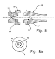
- FIG. 8 Yet another embodiment of a mixing chamber 8 according to the invention is shown in fig 8.
- This mixing chamber 8 has an inlet end piece 13 and an outlet end piece 14.
- the flow perturbation means 11 is constituted by two separate means.
- the outlet end piece 14, is provided with two chamfered shelves 12, similar to the shelves in fig 2, constituting a first flow perturbation means.
- the inlet end piece is provided with a second flow perturbation means 11, comprising two baffles 17, extending from the wall of the mixing chamber 8.
- the baffles 17 only extend just so far as to let the central passage 5 pass between them.
- the baffles 17 are further arranged in an angle against the central axes of the mixing chamber 8 in order to increase their effect on the flow.
- a third experiment was made using felodipine and the mixing chamber from fig 6.
- the test conditions were the same as in the first experiment with felodipine.
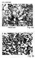
- both morphology and size of the particles are clearly different from the experiment using prior art, as seen from the SEM-graphs (fig 10a and b).
- the morphology obtained by using the mixing chamber from fig 6 is highly preferable to the morphology of prior art particles, since the particles are more uniform and considerably smoother.
- the size distributions using felodipine with different mixing chambers are shown in fig 13. Both of the mixing chambers according to the invention show a narrower size distribution that is also translated towards smaller particle sizes. As seen, for this particular substance, the mixing chamber according to fig 8 shows a better result than the mixing chamber according to fig 6. For an optimal result, each substance should be used together with a mixing chamber specifically adapted for that substance and the desired particle formation of said substance.
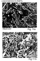
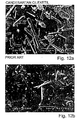
- candesartan cilexetil was used in similar experiments using the mixing chamber from fig 5 and fig 6.
- the resulting SEM-graphs are shown in fig 11a and b and 12 a and b, respectively.
- the running conditions in these experiments were 210 bar and 64 degrees C.
- the flow of the antisolvent (CO 2 ) was 12 ml/min and the flow rate of the solvent (acetone) was 0,3 ml/min.
- the differences between the resulting particles when using prior art and when using the different embodiments of the mixing chamber according to the invention is remarkable, as clearly seen in the SEM-graphs. Again, the morphology and the size distribution of the particles are advantageously affected by the controlled disorder in the fluid flow or flows. -
- the fluid perturbation means can for example be shaped like baffles extending from the walls of the mixing chamber, like grooves or protuberances in the mixing chamber wall or be constituted by the insertion of channels in such way to set the fluid inside the mixing chamber in rotation.
- the turbulence to be created before entering the mixing chamber, in the passages of the nozzle.
- the outer form of the mixing chamber can evidently have many different shapes adjusted to the shape of the nozzle used.
- Different flow perturbation means in the front or the end part of the mixing chamber can be put together as required for forming particles of a certain substance.
- the length of the passages 2, 5 entering the mixing chamber 8 might have an impact on the creation of turbulence.
Landscapes
- Chemical & Material Sciences (AREA)
- Chemical Kinetics & Catalysis (AREA)
- Health & Medical Sciences (AREA)
- Engineering & Computer Science (AREA)
- Bioinformatics & Cheminformatics (AREA)
- Organic Chemistry (AREA)
- Public Health (AREA)
- Pharmacology & Pharmacy (AREA)
- Animal Behavior & Ethology (AREA)
- General Health & Medical Sciences (AREA)
- Epidemiology (AREA)
- Veterinary Medicine (AREA)
- Medicinal Chemistry (AREA)
- Life Sciences & Earth Sciences (AREA)
- Dispersion Chemistry (AREA)
- Accessories For Mixers (AREA)
- Physical Or Chemical Processes And Apparatus (AREA)
- Mixers With Rotating Receptacles And Mixers With Vibration Mechanisms (AREA)
- Glanulating (AREA)
- Manufacturing Of Micro-Capsules (AREA)
Claims (21)
- Verfahren zum Bilden von Teilchen aus einer Substanz, umfassend den Schritt des Einbringens in eine Mischkammer (8), in der die Temperatur und der Druck kontrolliert werden, eines fluiden Gases, ausgewählt aus superkritischem, nahezu superkritischem und komprimiertem Gas (4); und mindestens eines Vehikelsystems (1), das mindestens eine Substanz in Lösung oder Suspension derart aufweist, dass Tröpfchenbildung und -extraktion aus dem Vehikel durch die Wirkung des fluiden Gases (4) im Wesentlichen gleichzeitig erfolgen; wobei in mindestens einem des fluiden Gases (4) und des Vehikelsystems (1) eine Turbulenz ausgelöst wird, so dass eine kontrollierte Störung in der Strömung von mindestens einem des fluiden Gases (4) oder des Vehikelsystems (1) ausgelöst wird, um die Teilchenbildung in der Mischkammer (8) zu kontrollieren, wobei die kontrollierte Störung durch mindestens ein Strömungsstörmittel (11) im Inneren der Mischkammer (8) oder angeordnet in mindestens einem der Durchgangswege, die die Fluide in die Mischkammer einspeisen, erzeugt wird, dadurch gekennzeichnet, dass das Strömungsstörmittel ein abstehendes Element umfasst, das für die Strömung ein Hindernis erzeugt.
- Verfahren nach Anspruch 1, wobei die Turbulenz oder Störung von mindestens einem des fluiden Gases (4) und des Vehikelsystems (1) durch das Fluid erzeugt wird, das mit mindestens einem Strömungsstörmittel (11), das im Inneren der Mischkammer (8) ausgebildet ist, wechselwirkt.
- Verfahren nach Anspruch 1 oder 2, wobei das fluide Gas ein superkritisches oder nahezu superkritisches Gas ist.
- Verfahren nach einem der Ansprüche 1 bis 3, wobei die Turbulenz kontrolliert wird, so dass die gewünschten Teilchen aus der mindestens einen speziellen Substanz gebildet werden.
- Verfahren nach einem der Ansprüche 1 bis 4, wobei die kontrollierte Störung durch das Fluid erzeugt wird, das mit dem Inneren der Mischkammer (8) wechselwirkt.
- Verfahren nach einem der Ansprüche 1 bis 5, wobei die kontrollierte Störung in mindestens einem des fluiden Gases (4) und des Vehikelsystems (1) in einem Bereich in der Nähe von oder im Anschluss an eine Auslassöffnung der Mischkammer (8) ausgelöst wird.
- Mischkammer (8) zur Verwendung bei der Bildung von Teilchen aus einer Substanz, wobei die Mischkammer (8) eine Kammer mit einem Einlass zur Aufnahme von mindestens einem ersten Zufuhrelement (5) mit einem Auslass zum Zuführen eines fluiden Gases, ausgewählt aus superkritischem, nahezu superkritischem und komprimiertem Gas (4), und mindestens einem zweiten Zufuhrelement (2) mit einem Auslass zum Zuführen eines Vehikelsystems (1), aufweisend mindestens eine Substanz in Lösung oder Suspension, und einem Auslass zum Absaugen der darin gebildeten Teilchen einschließt, und wobei mindestens ein Strömungsstörmittel (11) im Inneren der Mischkammer oder in mindestens einem der Durchgangswege, die die Fluide in die Mischkammer einspeisen, angeordnet ist, zur Wechselwirkung mit mindestens einem des fluiden Gases (4) oder des Vehikelsystems (1), das durch das mindestens eine Zufuhrelement (4, 5) bereitgestellt wird, so dass in dem mindestens einen des fluiden Gases (4) oder des Vehikelsystems (1) eine Turbulenz ausgelöst wird, um eine kontrollierte Störung in der Strömung des mindestens einen des fluiden Gases (4) oder des Vehikelsystems (1) zu erzeugen, um die Teilchenbildung in der Mischkammer (8) zu kontrollieren, dadurch gekennzeichnet, dass das Strömungsstörmittel ein abstehendes Element umfasst, das ein Hindernis für die Strömung erzeugt.
- Mischkammer nach Anspruch 7, wobei das Strömungsstörmittel (11) zur Auslösung einer Turbulenz ausgelegt ist, die kontrolliert wird, so dass die gewünschten Teilchen der mindestens einen speziellen Substanz gebildet werden.
- Mischkammer nach einem der Ansprüche 7 und 8, wobei das abstehende Element in der Mischkammer (8) angeordnet ist.
- Mischkammer nach Anspruch 9, wobei das abstehende Element im Umfang der inneren Wände der Kammer ausgebildet ist.
- Mischkammer nach einem der Ansprüche 9 bis 10, wobei das abstehende Element von mindestens einem Brett (12) in der Wand der Mischkammer (8) aufgebaut ist.
- Mischkammer nach einem der Ansprüche 9 bis 10, wobei das abstehende Element von mindestens einem Prallblech (17), das von der Mischkammerwand absteht, aufgebaut ist.
- Mischkammer nach einem der Ansprüche 7 bis 11, wobei das abstehende Element so angeordnet ist, dass eine Turbulenz in mindestens einem des fluiden Gases (4) und des Vehikelsystems (1) in einem Bereich in der Nähe oder im Anschluss an den Auslassteil der Mischkammer (8) hervorgerufen wird.
- Mischkammer nach einem der Ansprüche 9 bis 13, wobei das abstehende Element von einem Stöpsel (15) aufgebaut ist, der in der Mischkammer angeordnet ist, wobei der Stöpsel (15) mit einem Kanal (16) versehen ist.
- Mischkammer nach Anspruch 14, wobei die Richtung des Kanals (16) in dem Stöpsel (15) bezüglich der Richtung der Fluidströmungen in der Mischkammer (8) geneigt ist.
- Mischkammer nach Anspruch 12, wobei das abstehende Element aus zwei Prallblechen (17) aufgebaut ist, die von den gegenüberliegenden Wänden der Mischkammer abstehen.
- Mischkammer nach Anspruch 12 oder 16, wobei das Prallblech (17) bezüglich der zentralen Achsen der Mischkammer (8) geneigt ist.
- Mischkammer nach einem der Ansprüche 7 bis 17, wobei die Mischkammer (8) erste und zweite Körperteile (13, 14) umfasst, die lösbar miteinander gekoppelt sind.
- Anlage zur Erzeugung von teilchenförmigen Produkten, bestehend aus einer Vehikelsystem-Zufuhr, einer Fluidgas-Zufuhr, einer Mischkammer (8) nach einem der Ansprüche 7 bis 18, einem ersten und einem zweiten Durchgang zum gemeinsamen Einleiten eines Vehikelsystems und eines fluiden Gases in die Mischkammer.
- Verwendung der Anlage nach Anspruch 7 zur Herstellung eines teilchenförmigen Produkts aus einer Substanz, wobei die Substanz Felodipin oder Candesartan-cilexetil ist.
- Verfahren nach Anspruch 1 zur Herstellung eines teilchenförmigen Produkts aus einer Substanz, wobei die Substanz Felodipin oder Candesartan-cilexetil ist.
Applications Claiming Priority (3)
| Application Number | Priority Date | Filing Date | Title |
|---|---|---|---|
| SE9901667 | 1999-05-07 | ||
| SE9901667A SE9901667D0 (sv) | 1999-05-07 | 1999-05-07 | Method and device for forming particles |
| PCT/SE2000/000877 WO2000067892A1 (en) | 1999-05-07 | 2000-05-04 | Method and device for forming particles |
Publications (2)
| Publication Number | Publication Date |
|---|---|
| EP1191998A1 EP1191998A1 (de) | 2002-04-03 |
| EP1191998B1 true EP1191998B1 (de) | 2005-08-24 |
Family
ID=20415513
Family Applications (1)
| Application Number | Title | Priority Date | Filing Date |
|---|---|---|---|
| EP00930027A Expired - Lifetime EP1191998B1 (de) | 1999-05-07 | 2000-05-04 | Verfahren und vorrichtung zur herstellung von teilchen |
Country Status (13)
| Country | Link |
|---|---|
| US (1) | US6551532B1 (de) |
| EP (1) | EP1191998B1 (de) |
| JP (1) | JP2002543961A (de) |
| KR (1) | KR20020013871A (de) |
| CN (1) | CN1350475A (de) |
| AT (1) | ATE302647T1 (de) |
| AU (1) | AU759786B2 (de) |
| CA (1) | CA2368087A1 (de) |
| DE (1) | DE60022195T2 (de) |
| MX (1) | MXPA01011099A (de) |
| NZ (1) | NZ515146A (de) |
| SE (1) | SE9901667D0 (de) |
| WO (1) | WO2000067892A1 (de) |
Families Citing this family (17)
| Publication number | Priority date | Publication date | Assignee | Title |
|---|---|---|---|---|
| GB0027357D0 (en) | 2000-11-09 | 2000-12-27 | Bradford Particle Design Plc | Particle formation methods and their products |
| ATE274995T1 (de) | 2001-02-26 | 2004-09-15 | Dompe Spa | Apparat und methode zur bildung von mikro- und submikropartikeln |
| FR2824754B1 (fr) * | 2001-05-15 | 2004-05-28 | Separex Sa | Procede d'obtention de particules solides a partir d'au moins un produit hydrosoluble |
| GB0208742D0 (en) | 2002-04-17 | 2002-05-29 | Bradford Particle Design Ltd | Particulate materials |
| EP1494796B1 (de) * | 2002-04-12 | 2014-06-04 | Feyecon B.V. | Verfahren zur herstellung von kleinen teilchen |
| US7582284B2 (en) | 2002-04-17 | 2009-09-01 | Nektar Therapeutics | Particulate materials |
| US6998051B2 (en) * | 2002-07-03 | 2006-02-14 | Ferro Corporation | Particles from supercritical fluid extraction of emulsion |
| WO2004098561A2 (en) | 2003-05-08 | 2004-11-18 | Nektar Therapeutics Uk Ltd | Particulate materials |
| US7098342B2 (en) * | 2003-10-16 | 2006-08-29 | Teva Pharmaceutical Industries Ltd. | Preparation of candesartan cilexetil |
| WO2005077941A2 (en) * | 2004-02-11 | 2005-08-25 | Teva Pharmaceutical Industries Ltd. | Candesartan cilexetil polymorphs |
| CN1953973A (zh) * | 2004-05-05 | 2007-04-25 | 特瓦制药工业有限公司 | 高纯度坎地沙坦酯的制备 |
| WO2005123720A1 (en) * | 2004-06-18 | 2005-12-29 | Ranbaxy Laboratories Limited | Fine particles of the angiotensin ii antagonist candesartan cilexetil and process for production thereof |
| JP2008505935A (ja) * | 2005-05-10 | 2008-02-28 | テバ ファーマシューティカル インダストリーズ リミティド | 超微粉砕された安定性カンデサルタンシレキセチル及びその調製方法 |
| CA2667890C (en) * | 2006-10-31 | 2015-01-27 | Surmodics Pharmaceuticals, Inc. | Spheronized polymer particles |
| DK2425820T3 (en) | 2007-02-11 | 2015-07-13 | Map Pharmaceuticals Inc | A method for the therapeutic administration of DHE in order to enable quick relief of migraine, while minimizing the adverse event profile |
| ES2326402B1 (es) * | 2008-04-07 | 2010-08-10 | Activery Biotech, S.L. | Procedimiento para la preparacion de combinaciones amorfas de antagonistas del receptor de angiotensina ii y diureticos. |
| US9808030B2 (en) | 2011-02-11 | 2017-11-07 | Grain Processing Corporation | Salt composition |
Family Cites Families (22)
| Publication number | Priority date | Publication date | Assignee | Title |
|---|---|---|---|---|
| NL7402981A (de) | 1973-03-16 | 1974-09-18 | ||
| JPS5243163A (en) * | 1975-10-02 | 1977-04-04 | Matsushita Electric Ind Co Ltd | Mixer for fluid |
| US4179222A (en) | 1978-01-11 | 1979-12-18 | Systematix Controls, Inc. | Flow turbulence generating and mixing device |
| ES481924A1 (es) * | 1978-06-28 | 1980-09-01 | Gen Foods Ltd | Un procedimiento mejorado para obtener un producto alimenti-cio secado por pulverizacion, tal como cafe, destrina y si- milares. |
| NL8001874A (nl) * | 1980-03-29 | 1981-11-02 | Stamicarbon | Inrichting voor het versproeien van een vloeistof met behulp van een gas. |
| US4606939A (en) * | 1983-06-22 | 1986-08-19 | The Ohio State University Research Foundation | Small particle formation |
| JPS61138529A (ja) * | 1984-12-10 | 1986-06-26 | Idemitsu Petrochem Co Ltd | サイズ用乳化液の製造方法 |
| US4606940A (en) * | 1984-12-21 | 1986-08-19 | The Ohio State University Research Foundation | Small particle formation and encapsulation |
| CH669336A5 (de) * | 1985-12-11 | 1989-03-15 | Sulzer Ag | |
| DE3851106T2 (de) * | 1987-07-13 | 1994-12-01 | Kinematica Gmbh | Vorrichtung zum Mischen fliessfähiger Medien. |
| SE462704B (sv) | 1987-12-09 | 1990-08-20 | Hg Tech Ab | Foerfarande vid atomisering av vaetskor och anordning foer genomfoerande av foerfarandet |
| DE3744329A1 (de) | 1987-12-28 | 1989-07-06 | Schwarz Pharma Gmbh | Verfahren zur herstellung einer mindestens einen wirkstoff und einen traeger umfassenden zubereitung |
| AU624421B2 (en) | 1988-10-05 | 1992-06-11 | Pharmacia & Upjohn Company | Finely divided solid crystalline powders via precipitation into an anti-solvent |
| US5178325A (en) | 1991-06-25 | 1993-01-12 | Union Carbide Chemicals & Plastics Technology Corporation | Apparatus and methods for application of coatings with compressible fluids as diluent by spraying from an orifice |
| US5891471A (en) * | 1993-11-23 | 1999-04-06 | Euro-Celtique, S.A. | Pharmaceutical multiparticulates |
| GB9413202D0 (en) | 1994-06-30 | 1994-08-24 | Univ Bradford | Method and apparatus for the formation of particles |
| AU709384B2 (en) * | 1996-03-01 | 1999-08-26 | University Of Kansas, The | Methods and apparatus for particle precipitation and coating using near-critical and supercritical antisolvents |
| AU729905B2 (en) * | 1996-10-18 | 2001-02-15 | Alza Corporation | Multiple flow path device for oral delivery of discrete units |
| GB9703673D0 (en) * | 1997-02-21 | 1997-04-09 | Bradford Particle Design Ltd | Method and apparatus for the formation of particles |
| TW580397B (en) * | 1997-05-27 | 2004-03-21 | Takeda Chemical Industries Ltd | Solid preparation |
| US6342250B1 (en) * | 1997-09-25 | 2002-01-29 | Gel-Del Technologies, Inc. | Drug delivery devices comprising biodegradable protein for the controlled release of pharmacologically active agents and method of making the drug delivery devices |
| WO1999021534A1 (en) * | 1997-10-27 | 1999-05-06 | Merck Patent Gmbh | Solid state solutions and dispersions of poorly water soluble drugs |
-
1999
- 1999-05-07 SE SE9901667A patent/SE9901667D0/xx unknown
-
2000
- 2000-05-04 AU AU47923/00A patent/AU759786B2/en not_active Ceased
- 2000-05-04 WO PCT/SE2000/000877 patent/WO2000067892A1/en not_active Ceased
- 2000-05-04 CN CN00807307A patent/CN1350475A/zh active Pending
- 2000-05-04 JP JP2000616911A patent/JP2002543961A/ja active Pending
- 2000-05-04 US US09/600,068 patent/US6551532B1/en not_active Expired - Fee Related
- 2000-05-04 CA CA002368087A patent/CA2368087A1/en not_active Abandoned
- 2000-05-04 EP EP00930027A patent/EP1191998B1/de not_active Expired - Lifetime
- 2000-05-04 AT AT00930027T patent/ATE302647T1/de not_active IP Right Cessation
- 2000-05-04 KR KR1020017014121A patent/KR20020013871A/ko not_active Withdrawn
- 2000-05-04 NZ NZ515146A patent/NZ515146A/en unknown
- 2000-05-04 DE DE60022195T patent/DE60022195T2/de not_active Expired - Lifetime
- 2000-05-04 MX MXPA01011099A patent/MXPA01011099A/es unknown
Also Published As
| Publication number | Publication date |
|---|---|
| AU4792300A (en) | 2000-11-21 |
| EP1191998A1 (de) | 2002-04-03 |
| JP2002543961A (ja) | 2002-12-24 |
| WO2000067892A1 (en) | 2000-11-16 |
| US6551532B1 (en) | 2003-04-22 |
| AU759786B2 (en) | 2003-05-01 |
| CA2368087A1 (en) | 2000-11-16 |
| KR20020013871A (ko) | 2002-02-21 |
| ATE302647T1 (de) | 2005-09-15 |
| DE60022195T2 (de) | 2006-06-29 |
| DE60022195D1 (de) | 2005-09-29 |
| CN1350475A (zh) | 2002-05-22 |
| MXPA01011099A (es) | 2002-06-04 |
| SE9901667D0 (sv) | 1999-05-07 |
| NZ515146A (en) | 2003-07-25 |
Similar Documents
| Publication | Publication Date | Title |
|---|---|---|
| US6551532B1 (en) | Method and device for forming particles | |
| US8167279B2 (en) | Device, method and use for the formation of small particles | |
| US7635442B2 (en) | Apparatus and method for micron and submicron particle formation | |
| CA2447494A1 (en) | Method for manufacture of fine particles | |
| US20060279011A1 (en) | Particle formation | |
| US20050051917A1 (en) | Devices and methods for the production of particles | |
| Suo et al. | Micronization of the natural pigment-bixin by the SEDS process through prefilming atomization | |
| GB2398241A (en) | Particle formation | |
| WO2004110603A2 (en) | Method for preparation of particles from solution-in-supercritical fluid or compressed gas emulsions | |
| He et al. | Supercritical antisolvent micronization of natural carotene by the SEDS process through prefilming atomization | |
| EP1494796B1 (de) | Verfahren zur herstellung von kleinen teilchen | |
| JP2004148174A (ja) | 超臨界流体を利用して微粒子を製造する方法および装置 |
Legal Events
| Date | Code | Title | Description |
|---|---|---|---|
| PUAI | Public reference made under article 153(3) epc to a published international application that has entered the european phase |
Free format text: ORIGINAL CODE: 0009012 |
|
| 17P | Request for examination filed |
Effective date: 20011207 |
|
| AK | Designated contracting states |
Kind code of ref document: A1 Designated state(s): AT BE CH CY DE DK ES FI FR GB GR IE IT LI LU MC NL PT SE |
|
| AX | Request for extension of the european patent |
Free format text: AL;LT;LV;MK;RO;SI PAYMENT 20011207 |
|
| 17Q | First examination report despatched |
Effective date: 20030923 |
|
| GRAP | Despatch of communication of intention to grant a patent |
Free format text: ORIGINAL CODE: EPIDOSNIGR1 |
|
| GRAS | Grant fee paid |
Free format text: ORIGINAL CODE: EPIDOSNIGR3 |
|
| GRAA | (expected) grant |
Free format text: ORIGINAL CODE: 0009210 |
|
| RIN1 | Information on inventor provided before grant (corrected) |
Inventor name: GLAD, HAKAN Inventor name: BOISSIER, CATHERINE |
|
| AK | Designated contracting states |
Kind code of ref document: B1 Designated state(s): AT BE CH CY DE DK ES FI FR GB GR IE IT LI LU MC NL PT SE |
|
| AX | Request for extension of the european patent |
Extension state: SI |
|
| PG25 | Lapsed in a contracting state [announced via postgrant information from national office to epo] |
Ref country code: FI Free format text: LAPSE BECAUSE OF FAILURE TO SUBMIT A TRANSLATION OF THE DESCRIPTION OR TO PAY THE FEE WITHIN THE PRESCRIBED TIME-LIMIT Effective date: 20050824 Ref country code: BE Free format text: LAPSE BECAUSE OF FAILURE TO SUBMIT A TRANSLATION OF THE DESCRIPTION OR TO PAY THE FEE WITHIN THE PRESCRIBED TIME-LIMIT Effective date: 20050824 Ref country code: AT Free format text: LAPSE BECAUSE OF FAILURE TO SUBMIT A TRANSLATION OF THE DESCRIPTION OR TO PAY THE FEE WITHIN THE PRESCRIBED TIME-LIMIT Effective date: 20050824 Ref country code: NL Free format text: LAPSE BECAUSE OF FAILURE TO SUBMIT A TRANSLATION OF THE DESCRIPTION OR TO PAY THE FEE WITHIN THE PRESCRIBED TIME-LIMIT Effective date: 20050824 |
|
| REG | Reference to a national code |
Ref country code: GB Ref legal event code: FG4D |
|
| REG | Reference to a national code |
Ref country code: CH Ref legal event code: EP |
|
| REG | Reference to a national code |
Ref country code: IE Ref legal event code: FG4D |
|
| REF | Corresponds to: |
Ref document number: 60022195 Country of ref document: DE Date of ref document: 20050929 Kind code of ref document: P |
|
| REG | Reference to a national code |
Ref country code: SE Ref legal event code: TRGR |
|
| PG25 | Lapsed in a contracting state [announced via postgrant information from national office to epo] |
Ref country code: DK Free format text: LAPSE BECAUSE OF FAILURE TO SUBMIT A TRANSLATION OF THE DESCRIPTION OR TO PAY THE FEE WITHIN THE PRESCRIBED TIME-LIMIT Effective date: 20051124 Ref country code: GR Free format text: LAPSE BECAUSE OF FAILURE TO SUBMIT A TRANSLATION OF THE DESCRIPTION OR TO PAY THE FEE WITHIN THE PRESCRIBED TIME-LIMIT Effective date: 20051124 |
|
| REG | Reference to a national code |
Ref country code: CH Ref legal event code: NV Representative=s name: PATENTANWAELTE SCHAAD, BALASS, MENZL & PARTNER AG |
|
| PG25 | Lapsed in a contracting state [announced via postgrant information from national office to epo] |
Ref country code: PT Free format text: LAPSE BECAUSE OF FAILURE TO SUBMIT A TRANSLATION OF THE DESCRIPTION OR TO PAY THE FEE WITHIN THE PRESCRIBED TIME-LIMIT Effective date: 20060124 |
|
| NLV1 | Nl: lapsed or annulled due to failure to fulfill the requirements of art. 29p and 29m of the patents act | ||
| PG25 | Lapsed in a contracting state [announced via postgrant information from national office to epo] |
Ref country code: IE Free format text: LAPSE BECAUSE OF NON-PAYMENT OF DUE FEES Effective date: 20060504 |
|
| ET | Fr: translation filed | ||
| PG25 | Lapsed in a contracting state [announced via postgrant information from national office to epo] |
Ref country code: MC Free format text: LAPSE BECAUSE OF NON-PAYMENT OF DUE FEES Effective date: 20060531 |
|
| PLBE | No opposition filed within time limit |
Free format text: ORIGINAL CODE: 0009261 |
|
| STAA | Information on the status of an ep patent application or granted ep patent |
Free format text: STATUS: NO OPPOSITION FILED WITHIN TIME LIMIT |
|
| 26N | No opposition filed |
Effective date: 20060526 |
|
| REG | Reference to a national code |
Ref country code: IE Ref legal event code: MM4A |
|
| PG25 | Lapsed in a contracting state [announced via postgrant information from national office to epo] |
Ref country code: LU Free format text: LAPSE BECAUSE OF NON-PAYMENT OF DUE FEES Effective date: 20060504 |
|
| PG25 | Lapsed in a contracting state [announced via postgrant information from national office to epo] |
Ref country code: CY Free format text: LAPSE BECAUSE OF FAILURE TO SUBMIT A TRANSLATION OF THE DESCRIPTION OR TO PAY THE FEE WITHIN THE PRESCRIBED TIME-LIMIT Effective date: 20050824 |
|
| PG25 | Lapsed in a contracting state [announced via postgrant information from national office to epo] |
Ref country code: ES Free format text: LAPSE BECAUSE OF NON-PAYMENT OF DUE FEES Effective date: 20060531 |
|
| PGFP | Annual fee paid to national office [announced via postgrant information from national office to epo] |
Ref country code: FR Payment date: 20100525 Year of fee payment: 11 |
|
| PGFP | Annual fee paid to national office [announced via postgrant information from national office to epo] |
Ref country code: IT Payment date: 20100513 Year of fee payment: 11 Ref country code: DE Payment date: 20100531 Year of fee payment: 11 |
|
| PGFP | Annual fee paid to national office [announced via postgrant information from national office to epo] |
Ref country code: CH Payment date: 20100430 Year of fee payment: 11 |
|
| PGFP | Annual fee paid to national office [announced via postgrant information from national office to epo] |
Ref country code: SE Payment date: 20100507 Year of fee payment: 11 Ref country code: GB Payment date: 20100401 Year of fee payment: 11 |
|
| REG | Reference to a national code |
Ref country code: CH Ref legal event code: PL |
|
| REG | Reference to a national code |
Ref country code: SE Ref legal event code: EUG |
|
| GBPC | Gb: european patent ceased through non-payment of renewal fee |
Effective date: 20110504 |
|
| PG25 | Lapsed in a contracting state [announced via postgrant information from national office to epo] |
Ref country code: LI Free format text: LAPSE BECAUSE OF NON-PAYMENT OF DUE FEES Effective date: 20110531 Ref country code: CH Free format text: LAPSE BECAUSE OF NON-PAYMENT OF DUE FEES Effective date: 20110531 |
|
| REG | Reference to a national code |
Ref country code: FR Ref legal event code: ST Effective date: 20120131 |
|
| PG25 | Lapsed in a contracting state [announced via postgrant information from national office to epo] |
Ref country code: IT Free format text: LAPSE BECAUSE OF NON-PAYMENT OF DUE FEES Effective date: 20110504 |
|
| REG | Reference to a national code |
Ref country code: DE Ref legal event code: R119 Ref document number: 60022195 Country of ref document: DE Effective date: 20111201 |
|
| PG25 | Lapsed in a contracting state [announced via postgrant information from national office to epo] |
Ref country code: FR Free format text: LAPSE BECAUSE OF NON-PAYMENT OF DUE FEES Effective date: 20110531 |
|
| PG25 | Lapsed in a contracting state [announced via postgrant information from national office to epo] |
Ref country code: GB Free format text: LAPSE BECAUSE OF NON-PAYMENT OF DUE FEES Effective date: 20110504 |
|
| PG25 | Lapsed in a contracting state [announced via postgrant information from national office to epo] |
Ref country code: SE Free format text: LAPSE BECAUSE OF NON-PAYMENT OF DUE FEES Effective date: 20110505 |
|
| PG25 | Lapsed in a contracting state [announced via postgrant information from national office to epo] |
Ref country code: DE Free format text: LAPSE BECAUSE OF NON-PAYMENT OF DUE FEES Effective date: 20111201 |