EP1191727A2 - Modular erweiterbares optisches ADD-DROP-modul - Google Patents
Modular erweiterbares optisches ADD-DROP-modul Download PDFInfo
- Publication number
- EP1191727A2 EP1191727A2 EP01119845A EP01119845A EP1191727A2 EP 1191727 A2 EP1191727 A2 EP 1191727A2 EP 01119845 A EP01119845 A EP 01119845A EP 01119845 A EP01119845 A EP 01119845A EP 1191727 A2 EP1191727 A2 EP 1191727A2
- Authority
- EP
- European Patent Office
- Prior art keywords
- add
- channels
- drop
- drop module
- channel
- Prior art date
- Legal status (The legal status is an assumption and is not a legal conclusion. Google has not performed a legal analysis and makes no representation as to the accuracy of the status listed.)
- Granted
Links
Images

Classifications
-
- H—ELECTRICITY
- H04—ELECTRIC COMMUNICATION TECHNIQUE
- H04Q—SELECTING
- H04Q11/00—Selecting arrangements for multiplex systems
- H04Q11/0001—Selecting arrangements for multiplex systems using optical switching
- H04Q11/0005—Switch and router aspects
-
- H—ELECTRICITY
- H04—ELECTRIC COMMUNICATION TECHNIQUE
- H04J—MULTIPLEX COMMUNICATION
- H04J14/00—Optical multiplex systems
- H04J14/02—Wavelength-division multiplex systems
- H04J14/0201—Add-and-drop multiplexing
- H04J14/0202—Arrangements therefor
- H04J14/0209—Multi-stage arrangements, e.g. by cascading multiplexers or demultiplexers
-
- H—ELECTRICITY
- H04—ELECTRIC COMMUNICATION TECHNIQUE
- H04J—MULTIPLEX COMMUNICATION
- H04J14/00—Optical multiplex systems
- H04J14/02—Wavelength-division multiplex systems
- H04J14/0201—Add-and-drop multiplexing
- H04J14/0202—Arrangements therefor
- H04J14/021—Reconfigurable arrangements, e.g. reconfigurable optical add/drop multiplexers [ROADM] or tunable optical add/drop multiplexers [TOADM]
- H04J14/0212—Reconfigurable arrangements, e.g. reconfigurable optical add/drop multiplexers [ROADM] or tunable optical add/drop multiplexers [TOADM] using optical switches or wavelength selective switches [WSS]
-
- H—ELECTRICITY
- H04—ELECTRIC COMMUNICATION TECHNIQUE
- H04J—MULTIPLEX COMMUNICATION
- H04J14/00—Optical multiplex systems
- H04J14/02—Wavelength-division multiplex systems
- H04J14/0201—Add-and-drop multiplexing
- H04J14/0202—Arrangements therefor
- H04J14/0213—Groups of channels or wave bands arrangements
-
- H—ELECTRICITY
- H04—ELECTRIC COMMUNICATION TECHNIQUE
- H04J—MULTIPLEX COMMUNICATION
- H04J14/00—Optical multiplex systems
- H04J14/02—Wavelength-division multiplex systems
- H04J14/0201—Add-and-drop multiplexing
- H04J14/0215—Architecture aspects
- H04J14/0219—Modular or upgradable architectures
-
- H—ELECTRICITY
- H04—ELECTRIC COMMUNICATION TECHNIQUE
- H04Q—SELECTING
- H04Q11/00—Selecting arrangements for multiplex systems
- H04Q11/0001—Selecting arrangements for multiplex systems using optical switching
- H04Q11/0005—Switch and router aspects
- H04Q2011/0007—Construction
- H04Q2011/0016—Construction using wavelength multiplexing or demultiplexing
-
- H—ELECTRICITY
- H04—ELECTRIC COMMUNICATION TECHNIQUE
- H04Q—SELECTING
- H04Q11/00—Selecting arrangements for multiplex systems
- H04Q11/0001—Selecting arrangements for multiplex systems using optical switching
- H04Q11/0005—Switch and router aspects
- H04Q2011/0007—Construction
- H04Q2011/0024—Construction using space switching
-
- H—ELECTRICITY
- H04—ELECTRIC COMMUNICATION TECHNIQUE
- H04Q—SELECTING
- H04Q11/00—Selecting arrangements for multiplex systems
- H04Q11/0001—Selecting arrangements for multiplex systems using optical switching
- H04Q11/0005—Switch and router aspects
- H04Q2011/0052—Interconnection of switches
Definitions
- the invention relates to a modularly expandable optical ADD-DROP module.
- Wavelength division multiplex systems WDM systems and DWDM systems (D-Dense) are, for cost reasons, as purely optical Systems implemented. These systems require ADD-DROP multiplexer for decoupling individual ones Channels (more precisely: signals of a certain wavelength) and for adding channels (signals of the same wavelength) provided. To respond flexibly to customer requirements , the coupling and decoupling of wavelengths must be remotely configurable be and with minimal intervention in the system can be carried out.
- An ADD-DROP multiplexer is made by Marconi manufactured, in which a supplied WDM signal in parallel Channels are split, which are either switched through or be coupled in and out. Be through a WDM multiplexer the channels are combined again on the output side.
- An extension the ADD-DROP capacity is not with this concept possible.
- the object of the invention is an expandable ADD-DROP module to be specified with low insertion loss.
- the particular advantage of the ADD-DROP module is that the "to be looped through" the non-ADD drop switching units Signals are only slightly attenuated. This can at least one more via a cascade switching unit ADD-DROP module of approximately the same structure become.
- An ADD-DROP module with branch options is particularly advantageous for two channels. This ADD-DROP capacity is enough already in very many cases, and an extension with another module results in almost always sufficient ADD-DROP capacity of four channels.
- A can be used as a filter unit to select the ADD-DROP channels Wavelength demultiplexers are used that differ has wide pass bands. This can also can advantageously be realized from optical individual filters, preferably as a Bragg grating. In these, the reflected Waveband only slightly damped and can therefore the cascaded ADD-DROP module.
- 2 switches are preferably used as optical switching units, in which the signals from two inputs can be switched through to two outputs as desired .
- optical attenuators in the signal paths. This is especially true for the signal path of the branches to be looped through. Particularly advantageous there is an optical in the signal path of these channels Insert attenuator with constant value and the ADD-DROP switching units upstream variable attenuators.
- An additional filter can be used to select the branched channels be further improved.
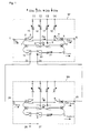
- FIG. 1 two ADD-DROP modules M1 and M2 are shown. Both modules have the same structure, which is why only the components of the first module have been given reference symbols.
- a WDM signal C N with N channels is fed to a WDM signal input 1. This reaches a first channel filter 2, which causes a channel Ca to be switched through and feeds the remaining Na channels to a further channel filter 7. This selects a further channel Cb, while the remaining Nab channels C Na, b are fed to a cascading switching unit 19, 20.
- Each channel Ca, Cb which can be branched off is in each case an ADD drop switching device 3, 4 and 8, 9 respectively.
- the first switch 3 enables branching of the channel Ca, which is then designated as DROP channel CDa or switching through this channel.
- the switch 4 enables the insertion of an ADD channel CAa or switching through (looping through) the channel approx.
- the channels C Na, b to be looped through are routed via the cascading switching unit 19, 20 and - in the switch position shown - via an attenuator 21 and ADD filter 10 and 5 (WDM multiplexer), where they are connected to the branched or inserted channels be combined to form the WDM output signal Co N and then arrive at the WDM signal output 6.
- WDM multiplexer WDM multiplexer
- an optical attenuator 21 is arranged in the signal branch of the channels C Na, b to be looped through.
- the levels of the DROP and ADD channels can be adjusted by attenuators 15 to 18.
- the WDM signal input 24 and the WDM signal output 25 of a further module M2 of essentially the same structure are connected to the cascading connections 22, 23 of the first module M1.
- the channels C Na, b to be looped through now reach the input 24 of the second module M2.
- two further channels Cc, Cd are fed to two further ADD-DROP devices, which can either branch off or switch these channels through.
- the ADD channels switched through or newly inserted are combined with the channels C Na, b, c, d to be looped through to form a multiplex signal Co Na, b , fed to the cascading connection 23 of the first module and via the ADD filters 10 and 5 combined to the newly configured WDM output signal Co N.
- a further one can be connected via connections 26 and 27 of the second module Cascading can be made.
- FIG. 2 shows a preferred embodiment of the invention.
- the switches 3 and 4 or 8 and 9 are replaced by 2: 2 switches 3, 4 and 3, 9, respectively.
- the channels C Na, b to be looped through in the first module are passed through a further filter 30, which serves as a bandpass filter and improves the attenuation of the channels Ca and Cb which can be branched off.
- the optical attenuator 21 is inserted between the switches 19 and 20 as an attenuator with a fixed value.
- the other channel levels are adjusted by means of variable attenuators 28 and 29 which are connected upstream of the ADD-DROP switching devices 3, 4 and 8, 9.
- the cascading switching device 31, 32 of the second module can be dispensed with and the channels to be looped through can be guided directly via an attenuator 33.
- the cascading connections 26, 27 are then also not required.
Landscapes
- Engineering & Computer Science (AREA)
- Computer Networks & Wireless Communication (AREA)
- Signal Processing (AREA)
- Optical Communication System (AREA)
Abstract
Description
- Figur 1
- ein Prinzipschaltbild der Erfindung und
- Figur 2
- ein bevorzugtes Ausführungsbeispiel.
Claims (8)
- Modular erweiterbares optisches ADD-DROP-Modul (M1), das enthälteine erste Filteranordnung (2, 7), der ein WDM-Signal (CN) zugeführt wird und die mindestens einen abzweigbaren Kanal (Ca) selektiert,mindestens eine ADD-Drop-Schalteinrichtung (3, 4), der der abzweigbare Kanal (Ca) zugeführt wird und die Umschalter (3 und 4) zum Durchschalten dieses Kanals (Ca) oder zum Abzweigen und zum Einfügen eines entsprechenden Kanals (CAa) aufweist,eine Kaskadier-Schalteinheit (19, 20), der von der ersten Filteranordnung (2, 7) durchzuschleifende Kanäle (CN-a,b) zugeführt werden und die diese entweder durchschaltet oder einem zweiten im Wesentlichen gleichen ADD-DROP-Modul (M2) zuführt und dessen WDM-Ausgangssignal (CoN-a,b) empfängt,eine ADD-Filteranordnung (5, 10) zum Zusammenfassen der abzweigbaren Kanäle (Ca, Cb) und der durchzuschleifenden Kanäle (CN-a,b) des ersten ADD-DROP-Moduls (M1) und bei einem kaskadierten weiteren Modul (M2) gegebenenfalls der abzweigbaren Kanäle (Ca, Cb, Cc, Cd) und der durchzuschleifenden Kanäle (CN-a,b,c,d) des ersten ADD-DROP-Moduls (M1) und des zweiten ADD-DROP-Moduls (M2) zu einem neu konfigurierten WDM-Ausgangssignal (CON).
- ADD-DROP-Modul nach Anspruch 1,
dadurch gekennzeichnet, dass eine Filteranordnung (2, 7) vorgesehen ist, die zwei Kanäle (Ca, Cb) selektiert. - ADD-DROP-Modul nach Anspruch 1 oder Anspruch 2,
dadurch gekennzeichnet, dass als erste Filtereinheit (2, 7) und/oder als ADD-Filtereinheit (5, 10) kaskadierte Einzelfilter vorgesehen sind. - ADD-DROP-Modul nach einem der vorhergehenden Ansprüche,
dadurch gekennzeichnet, dass als ADD-Drop-Schalteinrichtung (3, 4; 8, 9)) ein optischer 2:2-Schalter vorgesehen ist. - ADD-DROP-Modul nach einem der vorhergehenden Ansprüche,
dadurch gekennzeichnet, dass im Signalpfad der durchzuschleifenden Kanäle (CN-a,b) ein optisches Dämpfungsglied (21) angeordnet ist. - ADD-DROP-Modul nach einem der vorhergehenden Ansprüche,
dadurch gekennzeichnet, dass einstellbare Dämpfungsglieder (28, 29) den ADD-Drop-Schalteinrichtungen (3, 4; 8, 9) vorgeschaltet sind. - ADD-DROP-Modul nach einem der vorhergehenden Ansprüche,
dadurch gekennzeichnet, dass ein weiteres Filter (30) zur Dämpfung der abzweigbaren Kanäle (Ca, Cb) der Kaskadier-Schalteinrichtung (19, 20) vorgeschaltet ist. - ADD-DROP-Modul nach einem der vorhergehenden Ansprüche,
dadurch gekennzeichnet, dass das optisches Dämpfungsglied (21) zwischen einem ersten Ausgang eines ersten Umschalters (19) und eines zweiten Umschalter (20) der Kaskadier-Schalteinrichtung (19, 20) eingeschaltet ist.
Applications Claiming Priority (2)
| Application Number | Priority Date | Filing Date | Title |
|---|---|---|---|
| DE10046585 | 2000-09-20 | ||
| DE10046585A DE10046585B4 (de) | 2000-09-20 | 2000-09-20 | Modular erweiterbares optisches ADD-DROP-Modul |
Publications (3)
| Publication Number | Publication Date |
|---|---|
| EP1191727A2 true EP1191727A2 (de) | 2002-03-27 |
| EP1191727A3 EP1191727A3 (de) | 2006-06-28 |
| EP1191727B1 EP1191727B1 (de) | 2008-03-12 |
Family
ID=7656965
Family Applications (1)
| Application Number | Title | Priority Date | Filing Date |
|---|---|---|---|
| EP01119845A Expired - Lifetime EP1191727B1 (de) | 2000-09-20 | 2001-08-16 | Modular erweiterbares optisches ADD-DROP-modul |
Country Status (3)
| Country | Link |
|---|---|
| US (1) | US6795606B2 (de) |
| EP (1) | EP1191727B1 (de) |
| DE (2) | DE10046585B4 (de) |
Cited By (1)
| Publication number | Priority date | Publication date | Assignee | Title |
|---|---|---|---|---|
| CN100395971C (zh) * | 2003-04-25 | 2008-06-18 | 波若威科技股份有限公司 | 波长选择切换器 |
Families Citing this family (3)
| Publication number | Priority date | Publication date | Assignee | Title |
|---|---|---|---|---|
| US8442040B2 (en) * | 2005-06-30 | 2013-05-14 | Infinera Corporation | Modular adaptation and configuration of a network node architecture |
| US8774790B2 (en) * | 2006-02-15 | 2014-07-08 | Alcatel Lucent | Method and apparatus for improving wireless network reliability |
| US20070280688A1 (en) * | 2006-04-21 | 2007-12-06 | Matisse Networks | Upgradeable optical hub and hub upgrade |
Family Cites Families (10)
| Publication number | Priority date | Publication date | Assignee | Title |
|---|---|---|---|---|
| DE4337089C2 (de) * | 1993-10-29 | 2003-09-25 | Siemens Ag | Optisches, transparentes Ringnetz mit wahlweiser Durchschaltung oder Aus- und Einkopplung von Signalen in den Ringknoten |
| FR2720883B1 (fr) * | 1994-06-07 | 1997-01-10 | Cit Alcatel | Multiplexeur spectral optique à insertion-extraction. |
| FR2755253B1 (fr) * | 1996-10-24 | 1998-11-27 | Alsthom Cge Alcatel | Dispositif d'extraction-insertion de canaux de multiplex de longueurs d'onde |
| FI112569B (fi) * | 1997-05-13 | 2003-12-15 | Nokia Corp | Optinen add/drop-laite |
| CA2238606A1 (en) * | 1997-06-26 | 1998-12-26 | Michael Anthony Scobey | Cascaded optical multiplexing devices |
| AU9491398A (en) * | 1997-09-18 | 1999-04-05 | Corning Incorporated | Wavelength-selective optical switching apparatus, optical communications apparatus using the same, and method for use in the optical communications apparatus |
| FR2782588B1 (fr) * | 1998-08-24 | 2002-12-20 | Alsthom Cge Alkatel | Dispositif d'insertion/extraction de signaux optiques multiplexes en longueur d'onde |
| US6429974B1 (en) * | 2000-05-12 | 2002-08-06 | Mahi Networks | Add-drop multiplexer |
| US20020015552A1 (en) * | 2000-08-01 | 2002-02-07 | Link Gayle R. | Optical wavelength router |
| US6788899B2 (en) * | 2000-09-11 | 2004-09-07 | Winston I. Way | Dynamic wavelength add/drop multiplexer for UDWDM optical communication system |
-
2000
- 2000-09-20 DE DE10046585A patent/DE10046585B4/de not_active Expired - Fee Related
-
2001
- 2001-08-16 DE DE50113721T patent/DE50113721D1/de not_active Expired - Lifetime
- 2001-08-16 EP EP01119845A patent/EP1191727B1/de not_active Expired - Lifetime
- 2001-09-20 US US09/957,367 patent/US6795606B2/en not_active Expired - Lifetime
Cited By (1)
| Publication number | Priority date | Publication date | Assignee | Title |
|---|---|---|---|---|
| CN100395971C (zh) * | 2003-04-25 | 2008-06-18 | 波若威科技股份有限公司 | 波长选择切换器 |
Also Published As
| Publication number | Publication date |
|---|---|
| US20020044735A1 (en) | 2002-04-18 |
| DE10046585B4 (de) | 2007-10-25 |
| EP1191727A3 (de) | 2006-06-28 |
| DE50113721D1 (de) | 2008-04-24 |
| US6795606B2 (en) | 2004-09-21 |
| DE10046585A1 (de) | 2002-04-04 |
| EP1191727B1 (de) | 2008-03-12 |
Similar Documents
| Publication | Publication Date | Title |
|---|---|---|
| DE3856531T2 (de) | Zeit- und Wellenlängenmultiplex-Umschaltsystem | |
| DE60204542T2 (de) | Verschachtler und Entschachtler | |
| DE69938225T2 (de) | Querverbindungseinrichtung und Verfahren zur auf Raumvermittlung und Gruppierung von Kanälen basierte Vermittlung | |
| DE69736099T2 (de) | Vorrichtung zum Ein-und Ausfügen von Wellenlängenmultiplexkanälen | |
| DE10036700A1 (de) | Modularer optischer Netzwerkknoten | |
| EP1079248B1 (de) | Abstimmbares add-drop-continue-modul | |
| DE10046585B4 (de) | Modular erweiterbares optisches ADD-DROP-Modul | |
| DE102006008404B4 (de) | Optische Schaltungsstrukturen zur Realisierung eines Knotens höherer Ordnung in einem optischen Übertragungsnetzwerk sowie Basis- und Erweiterungsschaltungsstruktur | |
| DE60129936T2 (de) | Vorrichtung und verfahren zur wellenlängenselektiven schaltung | |
| EP1602188B1 (de) | Add-drop-einrichtung und cross-connect-einrichtung fuer wellenlaengen-multiplexsignale | |
| EP1151568B1 (de) | Netzknoten mit optischen add/drop-modulen | |
| DE19821245C1 (de) | Optischer Multiplexer und optischer Demultiplexer | |
| EP1997345B1 (de) | Wellenlängenselektiver schalter und verfahren zum kanalweisen schalten für einen wellenlängenselektiven schalter | |
| DE10212649B4 (de) | Cross-Connector für optische Signale | |
| EP1751896B1 (de) | Schaltung zur signalübertragung in einem netzwerkknoten, insbesondere für eine kanalkarte für eine optische wdm-signalübertragungseinrichtung | |
| DE69934058T2 (de) | Vorrichtung zum Ein-Ausfügen eines optischen Wellenlängenmultiplexsignales | |
| DE19906813C2 (de) | Add-Drop-Multiplexeinrichtung und optisches Wellenlängen-Multiplex-Übertragungssystem | |
| DE19518295C1 (de) | Optische Verstärkeranordnung | |
| DE10055476A1 (de) | Optisches Koppelfeld | |
| DE10309616A1 (de) | Optische Cross-Connect-Einrichtung | |
| WO2004066534A1 (de) | Optische filteranordnung für ein optisches wellenlängenmultiplex-übertragungssystem | |
| DE10300934B4 (de) | Optische Filteranordnung für ein optisches Wellenlängenmultiplex-Übertragungssystem | |
| EP1077552A2 (de) | Anordnung zum Abzweigen von optischen Signalen | |
| DE4203174A1 (de) | Kanalauswahlschaltung | |
| DE4213095A1 (de) | Optisches Schaltnetzwerk |
Legal Events
| Date | Code | Title | Description |
|---|---|---|---|
| PUAI | Public reference made under article 153(3) epc to a published international application that has entered the european phase |
Free format text: ORIGINAL CODE: 0009012 |
|
| AK | Designated contracting states |
Kind code of ref document: A2 Designated state(s): AT BE CH CY DE DK ES FI FR GB GR IE IT LI LU MC NL PT SE TR |
|
| AX | Request for extension of the european patent |
Free format text: AL;LT;LV;MK;RO;SI |
|
| PUAL | Search report despatched |
Free format text: ORIGINAL CODE: 0009013 |
|
| AK | Designated contracting states |
Kind code of ref document: A3 Designated state(s): AT BE CH CY DE DK ES FI FR GB GR IE IT LI LU MC NL PT SE TR |
|
| AX | Request for extension of the european patent |
Extension state: AL LT LV MK RO SI |
|
| 17P | Request for examination filed |
Effective date: 20061206 |
|
| AKX | Designation fees paid |
Designated state(s): DE FR GB IT |
|
| 17Q | First examination report despatched |
Effective date: 20070326 |
|
| RAP1 | Party data changed (applicant data changed or rights of an application transferred) |
Owner name: NOKIA SIEMENS NETWORKS GMBH & CO. KG |
|
| GRAP | Despatch of communication of intention to grant a patent |
Free format text: ORIGINAL CODE: EPIDOSNIGR1 |
|
| RAP3 | Party data changed (applicant data changed or rights of an application transferred) |
Owner name: NOKIA SIEMENS NETWORKS S.P.A. |
|
| RAP3 | Party data changed (applicant data changed or rights of an application transferred) |
Owner name: NOKIA SIEMENS NETWORKS GMBH & CO. KG |
|
| GRAS | Grant fee paid |
Free format text: ORIGINAL CODE: EPIDOSNIGR3 |
|
| GRAA | (expected) grant |
Free format text: ORIGINAL CODE: 0009210 |
|
| AK | Designated contracting states |
Kind code of ref document: B1 Designated state(s): DE FR GB IT |
|
| REG | Reference to a national code |
Ref country code: GB Ref legal event code: FG4D Free format text: NOT ENGLISH |
|
| REF | Corresponds to: |
Ref document number: 50113721 Country of ref document: DE Date of ref document: 20080424 Kind code of ref document: P |
|
| ET | Fr: translation filed | ||
| PLBE | No opposition filed within time limit |
Free format text: ORIGINAL CODE: 0009261 |
|
| STAA | Information on the status of an ep patent application or granted ep patent |
Free format text: STATUS: NO OPPOSITION FILED WITHIN TIME LIMIT |
|
| 26N | No opposition filed |
Effective date: 20081215 |
|
| REG | Reference to a national code |
Ref country code: DE Ref legal event code: R082 Ref document number: 50113721 Country of ref document: DE Representative=s name: BOEHMERT & BOEHMERT, DE |
|
| REG | Reference to a national code |
Ref country code: DE Ref legal event code: R081 Ref document number: 50113721 Country of ref document: DE Owner name: XIEON NETWORKS S.A.R.L., LU Free format text: FORMER OWNER: NOKIA SIEMENS NETWORKS GMBH & CO. KG, 81541 MUENCHEN, DE Effective date: 20131106 Ref country code: DE Ref legal event code: R082 Ref document number: 50113721 Country of ref document: DE Representative=s name: BOEHMERT & BOEHMERT, DE Effective date: 20131106 Ref country code: DE Ref legal event code: R082 Ref document number: 50113721 Country of ref document: DE Representative=s name: BOEHMERT & BOEHMERT ANWALTSPARTNERSCHAFT MBB -, DE Effective date: 20131106 |
|
| REG | Reference to a national code |
Ref country code: GB Ref legal event code: 732E Free format text: REGISTERED BETWEEN 20131212 AND 20131218 |
|
| REG | Reference to a national code |
Ref country code: GB Ref legal event code: 732E Free format text: REGISTERED BETWEEN 20140130 AND 20140205 |
|
| REG | Reference to a national code |
Ref country code: FR Ref legal event code: TP Owner name: XIEON NETWORKS S.A.R.L., LU Effective date: 20140408 Ref country code: FR Ref legal event code: GC Effective date: 20140408 |
|
| REG | Reference to a national code |
Ref country code: FR Ref legal event code: GC Effective date: 20150922 |
|
| REG | Reference to a national code |
Ref country code: FR Ref legal event code: PLFP Year of fee payment: 16 |
|
| PGFP | Annual fee paid to national office [announced via postgrant information from national office to epo] |
Ref country code: IT Payment date: 20160825 Year of fee payment: 16 |
|
| REG | Reference to a national code |
Ref country code: FR Ref legal event code: PLFP Year of fee payment: 17 |
|
| PGFP | Annual fee paid to national office [announced via postgrant information from national office to epo] |
Ref country code: GB Payment date: 20170822 Year of fee payment: 17 Ref country code: FR Payment date: 20170822 Year of fee payment: 17 Ref country code: DE Payment date: 20170822 Year of fee payment: 17 |
|
| PG25 | Lapsed in a contracting state [announced via postgrant information from national office to epo] |
Ref country code: IT Free format text: LAPSE BECAUSE OF NON-PAYMENT OF DUE FEES Effective date: 20170816 |
|
| REG | Reference to a national code |
Ref country code: DE Ref legal event code: R119 Ref document number: 50113721 Country of ref document: DE |
|
| GBPC | Gb: european patent ceased through non-payment of renewal fee |
Effective date: 20180816 |
|
| PG25 | Lapsed in a contracting state [announced via postgrant information from national office to epo] |
Ref country code: DE Free format text: LAPSE BECAUSE OF NON-PAYMENT OF DUE FEES Effective date: 20190301 |
|
| PG25 | Lapsed in a contracting state [announced via postgrant information from national office to epo] |
Ref country code: FR Free format text: LAPSE BECAUSE OF NON-PAYMENT OF DUE FEES Effective date: 20180831 |
|
| PG25 | Lapsed in a contracting state [announced via postgrant information from national office to epo] |
Ref country code: GB Free format text: LAPSE BECAUSE OF NON-PAYMENT OF DUE FEES Effective date: 20180816 |