EP1191709A1 - Spread spectrum receiving apparatus - Google Patents
Spread spectrum receiving apparatus Download PDFInfo
- Publication number
- EP1191709A1 EP1191709A1 EP01921922A EP01921922A EP1191709A1 EP 1191709 A1 EP1191709 A1 EP 1191709A1 EP 01921922 A EP01921922 A EP 01921922A EP 01921922 A EP01921922 A EP 01921922A EP 1191709 A1 EP1191709 A1 EP 1191709A1
- Authority
- EP
- European Patent Office
- Prior art keywords
- path
- signal
- interference
- paths
- beams
- Prior art date
- Legal status (The legal status is an assumption and is not a legal conclusion. Google has not performed a legal analysis and makes no representation as to the accuracy of the status listed.)
- Granted
Links
Images



Classifications
-
- H—ELECTRICITY
- H04—ELECTRIC COMMUNICATION TECHNIQUE
- H04B—TRANSMISSION
- H04B7/00—Radio transmission systems, i.e. using radiation field
- H04B7/02—Diversity systems; Multi-antenna system, i.e. transmission or reception using multiple antennas
- H04B7/04—Diversity systems; Multi-antenna system, i.e. transmission or reception using multiple antennas using two or more spaced independent antennas
- H04B7/08—Diversity systems; Multi-antenna system, i.e. transmission or reception using multiple antennas using two or more spaced independent antennas at the receiving station
- H04B7/0891—Space-time diversity
- H04B7/0897—Space-time diversity using beamforming per multi-path, e.g. to cope with different directions of arrival [DOA] at different multi-paths
-
- H—ELECTRICITY
- H04—ELECTRIC COMMUNICATION TECHNIQUE
- H04B—TRANSMISSION
- H04B1/00—Details of transmission systems, not covered by a single one of groups H04B3/00 - H04B13/00; Details of transmission systems not characterised by the medium used for transmission
- H04B1/69—Spread spectrum techniques
- H04B1/707—Spread spectrum techniques using direct sequence modulation
- H04B1/7097—Interference-related aspects
- H04B1/711—Interference-related aspects the interference being multi-path interference
- H04B1/7115—Constructive combining of multi-path signals, i.e. RAKE receivers
- H04B1/712—Weighting of fingers for combining, e.g. amplitude control or phase rotation using an inner loop
-
- H—ELECTRICITY
- H04—ELECTRIC COMMUNICATION TECHNIQUE
- H04B—TRANSMISSION
- H04B1/00—Details of transmission systems, not covered by a single one of groups H04B3/00 - H04B13/00; Details of transmission systems not characterised by the medium used for transmission
- H04B1/69—Spread spectrum techniques
- H04B1/707—Spread spectrum techniques using direct sequence modulation
- H04B1/7097—Interference-related aspects
- H04B1/711—Interference-related aspects the interference being multi-path interference
- H04B1/7113—Determination of path profile
Definitions
- the present invention relates to a spectrum spread receiver that uses a Code Division Multiple Access (CDMA) System which adopts a spectrum spread modulation system. More particularly, this invention relates to a spectrum spread receiver that carries out communications by using a transfer path in which a frequency selective fading is generated.
- CDMA Code Division Multiple Access
- Fig. 6 shows the construction of the conventional spectrum spread receiver.
- reference numerals 500, 501, ..., 502 are antennas the number of which is representedbyN (a natural number)
- 510, 511, ..., 512 are band-path filters (BPFs)
- 520, 521, ..., 522 are reverse spread sections
- 530, 531, ..., 532 are beam forming sections for individually forming beams from L (a natural number) paths generated based upon a signal after the reverse spread that has been subjected to an influence from a multi-path waveform
- 540 is a path detector
- 550, 551, ..., 552 are complex multipliers
- 553 is a delay unit
- 560 is a weight controlling section
- 561 is an adder
- 562 is a complex multiplier
- 563 is a complex conjugate calculator
- 564 is a subtracter
- 565 is a complex multiplier
- signals received from a mobile station by the N antennas 500, 501,..., 502 are filtered by the BPFs 510, 511, ..., 512, and subjected to desired band-width limitations.
- the signals after having been subjected to the band-width limitations are input into the reverse spread sections 520, 521, ..., 522 at which they are subjected to reverse spreads by the same sequence as the spread code sequence (corresponding to the PN sequence) that have been used on the transmission side.
- the path detector 540 selects L paths from a specific one of the signals that have been subjected to the reverse spread signal that has been influenced by the multi-path wave. A detailed explanation will be given of the operation of the path detector 540.
- Fig. 7 shows the construction of the path detector 540.
- reference numeral 600 is a transfer path estimating section
- 601 is an average power-value calculator
- 602 is a threshold value calculator
- 603 is a judgment section
- 604 is a path selector.
- the transfer path estimating section 600 adds all the symbols within one slot in the same phase based upon a pilot symbol (known signal) placed at a slot unit, and outputs a spontaneous transfer-path estimating value as a result.
- the average power value calculator 601 carries out an averaging operation of power over several slots by using the received transfer path estimating value, thereby calculating the average power delay profile as the result of the operation.
- the judgment section 603 compares the average power delay profile and the threshold value, and all the paths having average power values greater than the threshold value are set as the multi-paths corresponding to desired signals. Further, it outputs the time-sequential positional information of these paths and the power values of these paths.
- each beam forming section carries out a signal processing only on L paths preliminarily determined due to the limitations of H/W and S/W, the L paths are selected in the descending order from the greatest average power value.
- the time-sequential position corresponding to each path is output as the path position information.
- Fig. 8 shows the processes in the threshold value calculator 602, the judgment section 603 and the path selector 604.
- the beam forming sections 530, 531,..., 532 form beams by signal processes based upon an applicable algorithm.
- the beam forming section 530 is used for carrying out signal processing on the path having the greatest signal power
- the beam forming sections 531, ..., 532 are used for carrying out signal processing on the paths having the second greatest signal power to the L-th greatest signal power. The following description will discuss the operation of the beam forming section 530 in detail.
- the reverse spread signal from the reverse spread section 520 is separated by the path detector 540 into each path unit, and input into the beam forming section 530. Therefore, in each beam forming section, the beam is formed on a path unit basis that has been detected.
- the calculation of weight is carried out based upon an adaptive algorithm such as LMS (Least Mean Square), and in each of the complex multipliers 550, 551,..., 552, the signal received by each antenna is multiplied by a complex weight for forming a beam on the basis of a path. Then, the adder 561 combines the respective receiving signals that have been multiplied by the complex weights, and outputs the results of the combined as an antenna combined signal having directivity.
- LMS Least Mean Square
- the transfer path estimating section 570 estimates the transfer path. More specifically, for example, by using pilot symbols of a known sequence that are provided for the respective slots, a transfer path estimation value (complex value) with respect to the first path is calculated.
- Fig. 9 shows the slot construction.
- the complex conjugate calculator 563 calculates the complex conjugate value of the transfer path estimation value calculated in the transfer path estimating section 570. Then, the complex conjugate value is input into the complex multiplier 562 in which it is multiplied by the antenna combined signal, thus, a weighting process is carried out in proportion to the signal amplitude, and a signal from which a phase variation has been removed is output.
- the delay units 580, 581,..., 582 respectively add amounts of delay D 1 , D 2 , ..., D L thereto so that all the paths from the first path to the L-th path have the same timing.
- the adder 585 adds the signals which have been allowed to have the same phase on the basis of a path.
- the data decision section 590 performs a hard determination on the data.
- the result of the hard determination is output as demodulation data of the receiver.
- the delay units 583 to 584 respectively carry out delay adjustments so that, for example, amounts of delay, D L - D 1 , D L - D 2 , ..., 0 (where the L-th path is not subjected to a delay) are added thereto.
- the output of the delay unit 584 is multiplied by the transfer path estimation value in the complex multiplier 565, to form a reference signal. Thereafter, in the subtracter 564, the antenna combined signal is subtracted from the reference signal to generate an error signal e 1 (k) to be adaptive to the first path. Then, the weight controlling section 560 updates/determines the weight in accordance with equation (1) that indicates the normalization LMS.
- W 1 (k+1) W 1 (k)+ ⁇ X 1 (k- ⁇ ) X 1 (k- ⁇ ) 2 e 1 (k)
- the denominator of the second term on the right side of equation (1) represents a norm
- the initial value w 1 (0) of W 1 (k) [1, 0, ..., 0] T
- ⁇ represents the step size
- ⁇ represents a delay time (amount of delay).
- the conventional spectrum spread receiver with respect to L paths detected from the receiving signals received from a plurality of antennas, beams are individually formed (by using adaptive algorithms), that is, the SIR (signal to interference power ratio) with respect to a desired signal is improved while directing a null set to the interference signal by carrying out a weighting combining (Rake combining) in accordance with the transfer path estimation value.
- the conventional spectrum spread receiver is allowed to have an optimal channel capacity in the case when the positional distribution of mobile stations within a cell to which a base station can provide services is uniform and in the case when the beam interference power of beams formed on the basis of a path is the same.
- the selection of the path is carried out by utilizing a single antenna as described above.
- the resulting problem is that, in the case of using the single antenna, it is not possible to detect paths with high precision, in a transfer path under a great effect of interference.
- the weight is set to each receiving signal.
- a long period of time is required until the beam has been formed based upon the adaptive algorithm, and on the transmission side of the mobile station, much transmission signal power is required until the beam formation has been finished, in order to satisfy the predetermined quality on the base station. Consequently, an instantaneous increase occurs in the interference power, causing a failure to obtain an optimal channel capacity.
- the spectrum spread receiver which carries out a reverse spreading process on a signal received by a single antenna or a plurality of antennas, and also carries out a data demodulation process based upon the reverse spread signal, comprises: a path detection unit (corresponding to a path detector 140 which is described in the embodiments that will be described later) which detects a plurality of multi-path waves from the reverse spread signal, which have satisfied a predetermined standard and for outputting time-sequential positional information of the paths; a plurality of beam forming units (corresponding to complex multipliers 150 to 152 and an adder 161) which form beams by using an adaptive algorithm based upon the time-sequential positional information that is received on the basis of the path; a plurality of transfer path estimation units (corresponding to a transfer path estimating section 170 and a complex conjugate calculator 163) which calculate a transfer path estimation value based upon a receiving signal obtained on the basis of a beam, and carries out a weighting process in accordance
- the interference amount extraction unit calculates the amount of interference based upon a known sequence added to the transmission signal.
- the path detection unit comprises : a plurality of beam generating units (corresponding to a plurality of beams generating section 141) which generate a plurality of beams required for covering areas that are the service areas; a path detection unit (corresponding to path detectors 200, 210 and 220 on the basis of a beam) which detects all the paths having power values not less than a predetermined threshold value on the basis of a beam, and for normalizing the power value that has been detected based upon the interference power calculated for each of the beams; and a path selection unit (corresponding to a pass selector 330) which selects a predetermined number of paths among the paths that have been detected in a descending order from the biggest power value.
- the beam forming unit uses the weight obtained at the time of beam formation by the plurality of beam generating units.
- the adaptive algorithm is allowed to calculate an error signal by subtracting the received signal from the reference signal generated from the results of the determination, and also to generate a new error signal by carrying out an integral process by using a weighting coefficient on the error signal.
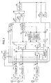
- Fig. 1 shows the construction of a spectrum spread receiver of a first embodiment of the present invention
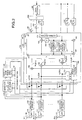
- Fig. 2 shows the construction of a spectrum spread receiver of a third embodiment of the present invention
- Fig. 3 shows a state in which a service area is covered by a plurality of beams
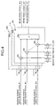
- Fig. 4 shows the construction of a beams generator
- Fig. 5 shows the construction of a time-space area path detector
- Fig. 6 shows the construction of a conventional spectrum spread receiver
- Fig. 7 shows the construction of a path detector
- Fig. 8 shows processes in a threshold-value calculator, a judgment section and a path selector
- Fig. 9 shows the construction of slots.
- the first embodiment is related to a spectrum spread receiver in which an adaptive array antenna is used.
- Fig. 1 shows the construction of a spectrum spread receiver in accordance with the first embodiment.
- reference numerals 100, 101, ..., 102 are antennas the number of which is represented by N (a natural number); 110, 111, ..., 112 are band-pass filters (BPFs) ; 120, 121, ..., 122 are reverse spread sections; 130, 131, ..., 132 are beam forming sections for individually forming beams based upon L (a natural number) paths generated by signals that have been subjected to the reverse spread under an influence of a multi-path wave; 140 is a path detector; 150, 151, ..., 152 are complex multipliers; 153 is a delay unit; 160 is a weight controlling section; 161 is an adder; 162 is a complex multiplier; 163 is a complex conjugate calculator; 164 is a substracter; 165 is a complex multiplier; 170 is a
- signals from mobile stations, received through N-number of antennas 100 to 102 are respectively wave-filtered by BPFs 110, 111, ..., 112 and subjected to desired band-width limitations.
- the signals that have been subjected to the band-width limitations are input into reverse spread sections 120, 121, ..., 122; and in this case, the reverse spreading operation is carried out by using the same sequence as the spread code sequence (corresponding to the PN-sequence) used in the transmission side.
- the path detector 140 selects L paths from one reverse spread signal that has been subjected to the influence of the multi-path wave, in the same manner as the conventional technique (see Fig. 7). More specifically, in the respective beam forming sections which will be described later, only L paths, which have been preliminarily defined based upon the limitations in H/W and S/W, are subjected to signal processing. Therefore, for example, L paths are selected from all the paths in the descending order from the one having the biggest average power value, and time-sequential positions corresponding to the respective paths are output as path position information.
- the beam forming sections 130, 131, ..., 132 form beams by the signal processing in the adaptive algorithm.
- he beam forming section 130 carries out the signal processing on the path having the greatest signal power in the same manner as the conventional device, and with respect to beam forming sections 131, ..., 132 also, they carry out the signal processing on the paths from the second greatest to the L-th greatest in the signal power, in the same manner as the conventional arrangement.
- the reverse spread signal from the above-mentioned reverse spread section 120 is separated by the path detector 140 on the basis of a path, and input into the beam forming section 130. Therefore, in each of the beam forming sections, a beam is formed on the basis of a detected path.
- the calculation of weight is carried out based upon an adaptive algorithm such as LMS (Least Mean Square), and in each of the complex multipliers 150 to 152, the signal received by each antenna is multiplied by a complex weight for forming a beam on the basis of a path. Then, the adder 161 combines the respective receiving signals that have been multiplied by the complex weights, and outputs the results of the combining as an antenna combined signal having directivity.
- LMS Least Mean Square
- the transfer path estimating section 170 estimates the transfer path. More specifically, by using pilot symbols (see Fig. 9) of a known sequence that are provided for the respective slots, a transfer path estimation value (complex value) with respect to the first path is calculated. Thereafter, in the complex conjugate calculator 163, a complex conjugate value of the transfer path estimation value calculated by the transfer path estimating section 170 is calculated. Then, this complex conjugate value is input into the complex multiplier 162 at which it is multiplied by the antenna combined signal; thus, a weighting process is carried out in proportion to the signal amplitude, and a signal from which a phase variation has been removed is output.
- the interference amount estimating section 171 calculates the interference amount from the output y 1 (k s , j ) of the adder 161 that is an antenna combined signal.
- k s indicates the order of the slots
- j represents the order of pilot symbols in the k s -th numbered slot.
- the interference amount estimating section 171 adds the pilot symbols P s (k s , j) within the k s -th slot corresponding to all the symbols in the same phase (here,
- 1), thereby calculating the transfer path estimation value ⁇ 1 (k s ).
- ⁇ 1 (k s ) is a complex number.
- the interference estimating section 171 calculates the interference amount ⁇ 1 2 (k s ) of the k s -th slot, by using the transfer path estimation value ⁇ 1 (k s ) and the output y 1 (k s , j) of the adder 161.
- P s *(k s , j) is a complex conjugate value of P s (k s , j), and P represents the number of pilot symbols within one slot.
- the interference amount estimating section 171 carries out an averaging process over a plurality of slots in accordance with equation (3), with respect to the interference amount ⁇ 1 2 (k s ) of the resulting k s -th slot; thus, the interference amount estimation value I 1 (k s ) of the k-th slot in the beam formed from the first path.
- S represents the number of slots used in the averaging process.
- the normalizing section 172 divides the signal that has been subjected to the weighting/phase variation removing process, that is, the output of the complex multiplier 162, by the interference amount estimation value I 1 (k s ), that is, the output of the interference amount estimating section 171, and outputs a normalized signal on the basis of a beam.
- the delay units 180, 181, ..., 182 respectively add amounts of delay D 1 , D 2 , ..., D L thereto so that all the paths from the first path to the L-th path have the same timing.
- the adder 185 signals which have been allowed to have the same phase on the basis of a path are combined, and in the data decision section 190, a hard determining process is carried out on the data; thus, the result of the hard determination is output as demodulation data of the receiver.
- the delay units 183 to 184 respectively carry out delay adjustments so that, for example, amounts of delay, D L - D 1 , D L - D 2 , ..., 0 (where the L-th path is not subjected to a delay) are added thereto.
- the beam forming section 130 receives the hard determination data to which the above-mentioned amounts of delay have been added, thereby determining the weights to be added to the respective receiving signals.
- known adaptive algorithms are used for forming the beams.
- the output of the delay unit 184 is multiplied by the transfer path estimation value by the complex multiplier 165 to form a reference signal. Thereafter, the subtracter 164 subtracts the antenna combined signal from the reference signal, thereby generating an error signal e 1 (k) for the first path. Then, the weight controlling section 160 updates/determines weights in accordance with the above-mentioned equation (1) representing the normalization LMS.
- the signal after the weighting process/the phase variation removing process which is the output from the complex multiplier 162 is combined after having been subjected to the weighting process in accordance with the interference amount, that is, after having been subjected to the normalization. Therefore, the SIR can be optimized, making it possible to obtain a superior bit error characteristic; consequently, it is possible to obtain an optimal channel capacity.
- the LMS is used for determining weights so as to determine beams.
- the adaptive algorithm is not intended to be limited by this, and for example, a known algorithm such as RLS may be used.
- the second embodiment carries out calculations of weights based upon an adaptive algorithm such as LMS; however, it is also characterized by carrying out an integral process in which a weighting process is applied to the error signal e 1 (k).
- an adaptive algorithm such as LMS
- those parts that are the same as those shown in Fig. 1 of the first embodiment are indicated by the same reference numerals, and the description thereof is omitted. Therefore, the following description will discuss the operation of the weight controlling section 160.
- the weight controlling section 160 receives the error signal e 1 (k) from the subtracter, and carries out an integral process on the error signal e 1 (k) by using a weighting coefficient ⁇ .
- E 1 (k+1) E 1 (k) + ⁇ e 1 (k)
- E 1 (k) is a complex number value.
- the weight controlling section 160 updates/determines the weight in accordance with equation (5) that indicates the normalization LMS.
- W 1 (k+1) W 1 (k)+ ⁇ X 1 (k- ⁇ ) X 1 (k- ⁇ ) 2 ⁇ (e 1 (k)+E 1 (k))
- the denominator of the second term on the right side of equation (5) represents a norm
- ⁇ represents the step size
- ⁇ represents a delay time (amount of delay).
- the second embodiment it is possible to obtain the same effects as the first embodiment, and also to carry out an integral process on the error signal e 1 (k) by using weighting coefficient ⁇ , consequently to emphasize its characteristics. Therefore, even in the case when the mobile station that is a communication target is shifted, and when the shifting speed is high, it is possible for the base station to direct a beam to the mobile station with high precision.
- FIG. 2 shows the construction of the second embodiment of a spectrum spread receiver in accordance with the present invention.
- those parts that are the same as those shown in the first or second embodiment are indicated by the same reference numerals, and the description thereof is omitted.
- reference numerals 130, 131, ..., 132 are beam forming sections for individually forming beams based upon L-number (natural number) of paths generated by signals that have been subjected to the reverse spreading process under an influence of multi-path waves
- reference numeral 141 is a beams generator
- 142 is a weight vector setting section
- 143 is a time space area path detector.
- the beams generator 141 covers the service areas by using the plurality of beams based upon the reverse spread signals received from the respective reverse spread sections.
- Fig. 3 shows a state in which the service areas are covered with the plurality of beams, and in this case, the covering is made by H-number (natural number) of beams.
- Fig. 4 shows the construction of the beams generator 141.
- reference numerals 200, 210, ..., 220 are beam forming sections
- 201, 202, ..., 203 are complex multipliers
- 204 is an adder.
- this beams generator 141 in order to form a beam corresponding to the first path in the H-number of beams, the multipliers 201 to 203 multiply a weight for forming the first beam that is output from the weight vector setting section 142 on the respective reverse spread signals . Then, the adder 204 adds all the results of the multiplications, and outputs a beam corresponding to the first path to the time space area path detector 143.
- the beams generator 141 in the same manner as described above, in order to form beams corresponding to the second to H-numbered path in the H-number of beams, weights for forming the second to H-numbered beams, output from the weight vector setting section 142, are multiplied on the respective reverse spread signals.
- a path detection is carried out on the basis of a beam.
- Fig. 5 shows the construction of the time space area path detector 143.
- reference numerals 300, 310, ..., 320 are beam-based path detectors for carrying out a path detection on the basis of a beam
- 301 is a transfer path estimating section
- 302 is an average power value calculator
- 303 is a threshold value calculator
- 304 is a determining section for determining the path
- 305 is an interference power value calculator
- 306 is a normalization section
- 330 is a path selector.
- the transfer path estimating section 301 estimates the transfer path based upon a beam-based signal #1 corresponding to the first beam. More specifically, the transfer path estimating section 301 adds all the symbols within one slot in the same phase by using pilot symbols that are provided on a slot basis to find an instantaneous transfer path estimation value.
- the average power value calculator 302 carries out an averaging operation of power over several slots by using the received transfer path estimating value, thereby calculating the average power delay profile as the result of the operation. Thereafter, in the threshold value calculator 303, among the received average power delay profiles, the path having the smallest power is regarded as noise or interference power, and the power value that is greater than the power by ⁇ dB is output as a threshold value used for the path selection.
- the determining section 304 compares the average power delay profile and the threshold value, and the paths having average power values greater than the threshold value are set as the multi-paths corresponding to desired signals. Further, it outputs the time-sequential positional information of these paths and the power values of these paths. The time-wise positional information on the path is output to the path selector 330, and the power value information of the path is on the other hand output to the normalization section for normalizing the interference power, respectively.
- the average power delay profile, the time-wise positional information and power value information of the path are input into the interference power value calculator 305, and the interference amount is estimated based upon the time-wise positional information and power value information of the path. More specifically, the interference power value calculator 305 adds all the average power profiles that have not been determined to have a path in a predetermined monitoring time range, and also averages this by the number of additions, thereby calculating the interference power of the beam.
- the normalizing section 306 divides the power value of the path by the beam interference power, and outputs the result of the division as a normalized power value.
- the path selector 330 first discriminates H-number of beam-based path detector output, based upon the beam discrimination information for discriminating which beam a piece of path information is derived from, that is, based upon the time-wise positional information of the path and the normalized power value. Then, since each beam forming section carries out a signal processing only on L paths preliminarily determined due to the limitations of H/W and S/W, the L paths are selected in the descending order from the greatest average power value. Moreover, the path selector 330 outputs the time-wise positional information of the selected path to each of the beam forming sections, and also outputs the time-wise positional information to the weight vector setting section 142. Here, the same processes are carried out on the second to the L-th paths.
- the weight vector setting section 142 sets the initial weight with respect to each of the beam forming sections on the basis of a path, based upon the result of the path detection by the time space area path detector 143.
- the initial weight set for each beam forming section it is designed that the weight at the time of the beam formation by the beams generator 141 is used so that the weight of the beam at the time when the path is detected by the time space area path detector 143 is set as the initial value of the beam on the basis of a path.
- the same setting method is carried out.
- the same effects as the first and second embodiments are obtained, and in the initial state in which the adaptive array antennas are used for forming a beam, the service area is covered by using a plurality of beams having predetermined directivities and the path detection is carried out based upon the interference power so that the interference power within the beamis suppressed. Therefore, even in a transfer path with a great influence of interference, it is possible to carry out the path detection with high precision.
- the beam discriminating information for discriminating which beam the path information is derived from is utilized and the weight at the time of the beam formation by the beams generator 141 is set as the initial value of the weight for the adaptive antennas.
- the LMS is used for determining weights so as to determine beams.
- the adaptive algorithm is not intended to be limited by this, and for example, a known algorithm such as RLS may be used.
- the signal after the weighting process/the phase variation removing process is combined after having been subjected to the weighting process in accordance with the interference amount, that is, after having been subjected to the normalization. Therefore, the SIR can be optimized, making it possible to obtain a superior bit error characteristic; consequently, it is possible to obtain a spectrum spread receiver that can achieve an optimal channel capacity.
- the service area is covered by using a plurality of beams having predetermined directivities and the path detection is carried out based upon the interference power so that the interference power within the beam is suppressed. Therefore, for example, it is possible to obtain a spectrum spread receiver which, even in a transfer path with a great influence of interference, can carry out the path detection with high precision.
- the beam discriminating information for discriminating which beam the path information is derived from the plurality of beams having the predetermined directivities is utilized so that the weight at the time of the beam formation by the plurality of beams generation step is set as the initial value of the weight of the adaptive antennas.
- the characteristic is emphasized by carrying out the integral process using consequently to emphasize its characteristics. Therefore, even in the case when the mobile station that is a communication target is shifted, and when the shifting speed is high, it is possible to provide a spectrum spread receiver which can direct a beam to the mobile station with high precision.
- the spectrum spread receiver in accordance with the present invention is suitable for carrying out communications by using a transfer path in which frequency selective fading is generated, and even in the case when the mobile station that is a communication target is shifted, and when the shifting speed is high, it is possible for the base station to direct a beam to the mobile station with high precision.
Landscapes
- Engineering & Computer Science (AREA)
- Computer Networks & Wireless Communication (AREA)
- Signal Processing (AREA)
- Radio Transmission System (AREA)
- Variable-Direction Aerials And Aerial Arrays (AREA)
- Mobile Radio Communication Systems (AREA)
- Synchronisation In Digital Transmission Systems (AREA)
- Digital Transmission Methods That Use Modulated Carrier Waves (AREA)
Abstract
Description


Claims (5)
- A spectrum spread receiver, which carries out a reverse spreading process on a signal received by a single antenna or a plurality of antennas, and also carries out a data demodulation process based upon the reverse spread signal, characterized by comprising:a path detection unit which detects a plurality of multi-path waves from the reverse spread signal, which have satisfied a predetermined standard and for outputting time-sequential positional information of the paths;a plurality of beam forming units which forms beams by using an adaptive algorithmbased upon the time-sequential positional information that is received on the basis of the path;a plurality of transfer path estimation units which calculate a transfer path estimation value based upon a receiving signal obtained on the basis of a beam, and carry out a weighting process in accordance with the signal amplitude and a removing process on the phase variation, based upon the results of the estimation;an interference amount extraction unit which extracts an amount of interference based upon the received signal obtained on the basis of a beam;a plurality of normalizing units which normalize the signals that have been subjected to the phase variation removing process based upon the amount of interference;a combining unit which combines all the signals that have been normalized; anda determining unit which determines the signal after the combining by the combining unit.
- The spectrum spread receiver according to claim 1, wherein the interference amount extraction unit calculates the amount of interference based upon a known sequence added to the transmission signal.
- The spectrum spread receiver according to claim 1, wherein the path detection unit comprises:a plurality of beam generating units which generate a plurality of beams required for covering areas that are the service areas;a path detection unit which detects all the paths having power values not less than a predetermined threshold value on the basis of a beam, and for normalizing the power value that has been detected based upon the interference power calculated for each of the beams; anda path selection unit which selects a predetermined number of paths among the paths that have been detected in a descending order from the biggest power value.
- The spectrum spread receiver according to claim 3, wherein, with respect to the initial value of the weight required for forming a beam using the adaptive algorithm, each of said beam forming unit uses the weight obtained at the time of beam formation by the plurality of beam generating units.
- The spectrum spread receiver according to claim 1, wherein the adaptive algorithm is allowed to calculate an error signal by subtracting the received signal from the reference signal generated from the results of the determination, and also to generate a new error signal by carrying out an integral process by using a weighting coefficient on the error signal.
Applications Claiming Priority (3)
| Application Number | Priority Date | Filing Date | Title |
|---|---|---|---|
| JP2000126467A JP4509297B2 (en) | 2000-04-26 | 2000-04-26 | Spread spectrum receiver |
| JP2000126467 | 2000-04-26 | ||
| PCT/JP2001/003365 WO2001082501A1 (en) | 2000-04-26 | 2001-04-19 | Spread spectrum receiving apparatus |
Publications (3)
| Publication Number | Publication Date |
|---|---|
| EP1191709A1 true EP1191709A1 (en) | 2002-03-27 |
| EP1191709A4 EP1191709A4 (en) | 2003-07-16 |
| EP1191709B1 EP1191709B1 (en) | 2007-06-13 |
Family
ID=18636246
Family Applications (1)
| Application Number | Title | Priority Date | Filing Date |
|---|---|---|---|
| EP01921922A Expired - Lifetime EP1191709B1 (en) | 2000-04-26 | 2001-04-19 | Spread spectrum receiving apparatus |
Country Status (6)
| Country | Link |
|---|---|
| US (1) | US6882681B2 (en) |
| EP (1) | EP1191709B1 (en) |
| JP (1) | JP4509297B2 (en) |
| CN (1) | CN1188963C (en) |
| DE (1) | DE60128874T2 (en) |
| WO (1) | WO2001082501A1 (en) |
Cited By (3)
| Publication number | Priority date | Publication date | Assignee | Title |
|---|---|---|---|---|
| EP1365521A1 (en) * | 2002-05-21 | 2003-11-26 | Nec Corporation | Path timing detection method for and adaptive array antenna system |
| EP1580843A4 (en) * | 2002-12-31 | 2006-02-15 | Zte Corp | Smart antenna, method and device for forming |
| CN104767553A (en) * | 2014-01-07 | 2015-07-08 | 瑞昱半导体股份有限公司 | Antenna diversity mechanism and beamforming mechanism coexistence control method |
Families Citing this family (36)
| Publication number | Priority date | Publication date | Assignee | Title |
|---|---|---|---|---|
| JP4081982B2 (en) * | 2001-01-30 | 2008-04-30 | 日本電気株式会社 | CDMA mobile communication demodulation circuit and demodulation method |
| JP3558053B2 (en) * | 2001-06-06 | 2004-08-25 | 日本電気株式会社 | Adaptive antenna receiver |
| JP2003008483A (en) * | 2001-06-18 | 2003-01-10 | Nec Corp | Adaptive array antenna receiver |
| US6947715B2 (en) * | 2002-03-30 | 2005-09-20 | Broadcom Corporation | VOFDM receiver correlation matrix processing using factorization |
| JP3895228B2 (en) * | 2002-05-07 | 2007-03-22 | 松下電器産業株式会社 | Wireless communication apparatus and direction of arrival estimation method |
| JP4008783B2 (en) * | 2002-08-23 | 2007-11-14 | 株式会社エヌ・ティ・ティ・ドコモ | Wireless communication system, wireless communication method, and base station suitable for these |
| WO2004021587A1 (en) * | 2002-08-29 | 2004-03-11 | Bae Systems Information And Electronic Systems Integration, Inc. | Method for separating interferering signals and computing arrival angles |
| WO2004021581A2 (en) * | 2002-08-29 | 2004-03-11 | Zyray Wireless, Inc. | Adaptive pilot interference cancellation in cdma systems |
| JP3955249B2 (en) * | 2002-09-13 | 2007-08-08 | 京セラ株式会社 | Array antenna system, directivity control method thereof, and mobile terminal |
| US7072635B2 (en) * | 2002-10-08 | 2006-07-04 | Freescale Semiconductor, Inc. | Method for combining data from phase indeterminate data streams for raking |
| US7596408B2 (en) * | 2002-12-09 | 2009-09-29 | Medtronic, Inc. | Implantable medical device with anti-infection agent |
| JP4096724B2 (en) * | 2002-12-12 | 2008-06-04 | 日本電気株式会社 | Multi-beam antenna receiving apparatus and multi-beam receiving method |
| US7783258B2 (en) * | 2003-02-14 | 2010-08-24 | Nortel Networks Limited | Wireless communication |
| US7558350B2 (en) * | 2003-03-04 | 2009-07-07 | Nec Corporation | Adaptive antenna reception device having excellent initial directional beam reception quality |
| CN100444531C (en) * | 2003-03-31 | 2008-12-17 | 富士通株式会社 | receiving device |
| KR100965721B1 (en) * | 2003-06-30 | 2010-06-24 | 삼성전자주식회사 | Apparatus and method for receiving data in mobile communication system using adaptive antenna array method |
| US7437135B2 (en) | 2003-10-30 | 2008-10-14 | Interdigital Technology Corporation | Joint channel equalizer interference canceller advanced receiver |
| US7308286B2 (en) * | 2003-11-20 | 2007-12-11 | Telefonaktiebolaget Lm Ericsson (Publ) | Multi-dimensional joint searcher and channel estimators |
| US7400692B2 (en) | 2004-01-14 | 2008-07-15 | Interdigital Technology Corporation | Telescoping window based equalization |
| JP2005260502A (en) * | 2004-03-10 | 2005-09-22 | Nec Corp | Communication equipment and communication control method |
| JP3895344B2 (en) * | 2004-09-09 | 2007-03-22 | 株式会社東芝 | Receiver |
| US8018930B2 (en) * | 2004-10-01 | 2011-09-13 | Qualcomm Incorporated | Apparatus and method for receiving packet data on a subset of carrier frequencies in a wireless communication system |
| US7787520B2 (en) * | 2004-10-06 | 2010-08-31 | Broadcom Corporation | Method and system for channel estimation in a single channel (SC) single-input multiple-output (SIMO) system |
| US20060269024A1 (en) * | 2005-05-27 | 2006-11-30 | Francis Dominique | Initial multi-path acquisition of random access channels |
| JP4449836B2 (en) * | 2005-06-27 | 2010-04-14 | 日本電気株式会社 | Adaptive antenna transceiver |
| US7929499B2 (en) * | 2005-07-13 | 2011-04-19 | Alcatel-Lucent Usa Inc. | Methods of multipath acquisition for dedicated traffic channels |
| JP4633600B2 (en) * | 2005-10-28 | 2011-02-16 | 京セラ株式会社 | Wireless communication apparatus and signal processing method thereof |
| US9231797B2 (en) * | 2007-11-28 | 2016-01-05 | Go Net Systems Ltd. | Dynamic threshold detector |
| TWI404380B (en) | 2010-04-30 | 2013-08-01 | Mstar Semiconductor Inc | Signal selection apparatus and method thereof |
| CN102255622B (en) * | 2010-05-17 | 2014-07-09 | 晨星软件研发(深圳)有限公司 | Signal selecting device and method |
| JP5609509B2 (en) * | 2010-10-04 | 2014-10-22 | 富士通株式会社 | Instruction system, instruction method, and storage control device. |
| WO2018051454A1 (en) * | 2016-09-15 | 2018-03-22 | 三菱電機株式会社 | Wireless reception device and desired signal detection method |
| JP6906966B2 (en) * | 2017-01-27 | 2021-07-21 | ラピスセミコンダクタ株式会社 | Signal detection circuit and signal detection method |
| DE102017110063A1 (en) * | 2017-03-02 | 2018-09-06 | Friedrich-Alexander-Universität Erlangen-Nürnberg | Method and device for environment detection |
| JP6992704B2 (en) * | 2018-08-22 | 2022-01-13 | 株式会社デンソー | Object detection device |
| US10693529B1 (en) * | 2019-09-30 | 2020-06-23 | Aeroantenna Technology, Inc. | Method and apparatus for multiplexing several antenna subsystem signals onto a single RF coaxial cable |
Family Cites Families (14)
| Publication number | Priority date | Publication date | Assignee | Title |
|---|---|---|---|---|
| JP2541503B2 (en) * | 1994-04-28 | 1996-10-09 | 日本電気株式会社 | Interference wave remover |
| SE503893C2 (en) * | 1994-07-15 | 1996-09-30 | Ericsson Telefon Ab L M | Method and apparatus for frequency hopping in a radio communication system |
| US6067292A (en) * | 1996-08-20 | 2000-05-23 | Lucent Technologies Inc | Pilot interference cancellation for a coherent wireless code division multiple access receiver |
| JPH10190495A (en) | 1996-12-20 | 1998-07-21 | Fujitsu Ltd | Interference canceller |
| JPH10303794A (en) * | 1997-02-27 | 1998-11-13 | Mitsubishi Electric Corp | Known sequence detector |
| JP2853742B2 (en) * | 1997-06-10 | 1999-02-03 | 日本電気株式会社 | Direct Spread / Code Division Multiplexing Interference Cancellation Receiver |
| JP2914445B2 (en) * | 1997-08-05 | 1999-06-28 | 日本電気株式会社 | CDMA adaptive receiver |
| JP3302634B2 (en) * | 1997-12-16 | 2002-07-15 | 松下電器産業株式会社 | Data communication device and method |
| JP2991179B2 (en) | 1998-01-08 | 1999-12-20 | 日本電気株式会社 | CDMA multi-user receiver |
| JPH11266180A (en) | 1998-03-18 | 1999-09-28 | Fujitsu Ltd | Array antenna system for wireless base station |
| JP3768350B2 (en) * | 1998-03-30 | 2006-04-19 | 松下電器産業株式会社 | Wireless receiving apparatus and method |
| JP3465739B2 (en) | 1998-04-07 | 2003-11-10 | 日本電気株式会社 | CDMA adaptive antenna receiving apparatus and communication system |
| JP2965202B1 (en) * | 1998-04-07 | 1999-10-18 | 日本電気株式会社 | Multi-user receiving apparatus and CDMA communication system |
| JP2000068910A (en) * | 1998-08-18 | 2000-03-03 | Kokusai Electric Co Ltd | Diversity receiver |
-
2000
- 2000-04-26 JP JP2000126467A patent/JP4509297B2/en not_active Expired - Fee Related
-
2001
- 2001-04-19 WO PCT/JP2001/003365 patent/WO2001082501A1/en not_active Ceased
- 2001-04-19 US US10/018,999 patent/US6882681B2/en not_active Expired - Fee Related
- 2001-04-19 DE DE2001628874 patent/DE60128874T2/en not_active Expired - Lifetime
- 2001-04-19 EP EP01921922A patent/EP1191709B1/en not_active Expired - Lifetime
- 2001-04-19 CN CNB018010970A patent/CN1188963C/en not_active Expired - Fee Related
Cited By (4)
| Publication number | Priority date | Publication date | Assignee | Title |
|---|---|---|---|---|
| EP1365521A1 (en) * | 2002-05-21 | 2003-11-26 | Nec Corporation | Path timing detection method for and adaptive array antenna system |
| EP1580843A4 (en) * | 2002-12-31 | 2006-02-15 | Zte Corp | Smart antenna, method and device for forming |
| CN104767553A (en) * | 2014-01-07 | 2015-07-08 | 瑞昱半导体股份有限公司 | Antenna diversity mechanism and beamforming mechanism coexistence control method |
| CN104767553B (en) * | 2014-01-07 | 2017-11-28 | 瑞昱半导体股份有限公司 | Control method and medium coexists with beam forming mechanism in antenna diversity mechanism |
Also Published As
| Publication number | Publication date |
|---|---|
| DE60128874D1 (en) | 2007-07-26 |
| DE60128874T2 (en) | 2008-02-21 |
| EP1191709B1 (en) | 2007-06-13 |
| US6882681B2 (en) | 2005-04-19 |
| US20020181561A1 (en) | 2002-12-05 |
| JP4509297B2 (en) | 2010-07-21 |
| JP2001308764A (en) | 2001-11-02 |
| WO2001082501A1 (en) | 2001-11-01 |
| EP1191709A4 (en) | 2003-07-16 |
| CN1366742A (en) | 2002-08-28 |
| CN1188963C (en) | 2005-02-09 |
Similar Documents
| Publication | Publication Date | Title |
|---|---|---|
| US6882681B2 (en) | Spread spectrum receiving apparatus | |
| US6064338A (en) | Array antenna system of wireless base station | |
| US6385181B1 (en) | Array antenna system of wireless base station | |
| JP4531969B2 (en) | Adaptive antenna receiver | |
| US7031368B1 (en) | Adaptive transmitter/receiver | |
| US7209512B2 (en) | CDMA receiver, and searcher in a CDMA receiver | |
| US6956841B1 (en) | Receiver and method of receiving a desired signal | |
| US20030069047A1 (en) | Adaptive array antenna directivity control system | |
| KR100451278B1 (en) | Adaptive antenna receiving apparatus | |
| US7161976B2 (en) | Interference canceller | |
| RU2232485C2 (en) | Procedure to form directivity pattern of antenna and device for its realization | |
| US7010023B1 (en) | Path search circuit for simultaneously performing antenna directivity control and path search | |
| US6968169B2 (en) | Receiver | |
| US20070189362A1 (en) | Method and system for channel estimation, related receiver and computer program product | |
| EP1365521B1 (en) | Path timing detection method for and adaptive array antenna system | |
| JP4183134B2 (en) | Smart antenna and beam forming method and apparatus thereof | |
| US7505509B2 (en) | Receiving communication apparatus using array antenna | |
| US7558350B2 (en) | Adaptive antenna reception device having excellent initial directional beam reception quality | |
| JP2004080191A (en) | Weight estimation method, weight estimation apparatus, interference cancellation apparatus and receiver having the same | |
| Kim et al. | Performance of antenna arrays with reverse-link synchronous transmission technique for DS-CDMA system in multipath fading channels |
Legal Events
| Date | Code | Title | Description |
|---|---|---|---|
| PUAI | Public reference made under article 153(3) epc to a published international application that has entered the european phase |
Free format text: ORIGINAL CODE: 0009012 |
|
| 17P | Request for examination filed |
Effective date: 20011214 |
|
| AK | Designated contracting states |
Kind code of ref document: A1 Designated state(s): AT BE CH CY DE DK ES FI FR GB GR IE IT LI LU MC NL PT SE TR |
|
| A4 | Supplementary search report drawn up and despatched |
Effective date: 20030602 |
|
| 17Q | First examination report despatched |
Effective date: 20031016 |
|
| RBV | Designated contracting states (corrected) |
Designated state(s): DE FR GB |
|
| RAP1 | Party data changed (applicant data changed or rights of an application transferred) |
Owner name: MITSUBISHI DENKI KABUSHIKI KAISHA |
|
| GRAP | Despatch of communication of intention to grant a patent |
Free format text: ORIGINAL CODE: EPIDOSNIGR1 |
|
| GRAS | Grant fee paid |
Free format text: ORIGINAL CODE: EPIDOSNIGR3 |
|
| GRAA | (expected) grant |
Free format text: ORIGINAL CODE: 0009210 |
|
| AK | Designated contracting states |
Kind code of ref document: B1 Designated state(s): DE FR GB |
|
| REG | Reference to a national code |
Ref country code: GB Ref legal event code: FG4D |
|
| REF | Corresponds to: |
Ref document number: 60128874 Country of ref document: DE Date of ref document: 20070726 Kind code of ref document: P |
|
| ET | Fr: translation filed | ||
| PLBE | No opposition filed within time limit |
Free format text: ORIGINAL CODE: 0009261 |
|
| STAA | Information on the status of an ep patent application or granted ep patent |
Free format text: STATUS: NO OPPOSITION FILED WITHIN TIME LIMIT |
|
| 26N | No opposition filed |
Effective date: 20080314 |
|
| PGFP | Annual fee paid to national office [announced via postgrant information from national office to epo] |
Ref country code: GB Payment date: 20100325 Year of fee payment: 10 |
|
| PGFP | Annual fee paid to national office [announced via postgrant information from national office to epo] |
Ref country code: FR Payment date: 20100521 Year of fee payment: 10 |
|
| PGFP | Annual fee paid to national office [announced via postgrant information from national office to epo] |
Ref country code: DE Payment date: 20100430 Year of fee payment: 10 |
|
| GBPC | Gb: european patent ceased through non-payment of renewal fee |
Effective date: 20110419 |
|
| REG | Reference to a national code |
Ref country code: FR Ref legal event code: ST Effective date: 20111230 |
|
| PG25 | Lapsed in a contracting state [announced via postgrant information from national office to epo] |
Ref country code: FR Free format text: LAPSE BECAUSE OF NON-PAYMENT OF DUE FEES Effective date: 20110502 Ref country code: DE Free format text: LAPSE BECAUSE OF NON-PAYMENT OF DUE FEES Effective date: 20111101 |
|
| REG | Reference to a national code |
Ref country code: DE Ref legal event code: R119 Ref document number: 60128874 Country of ref document: DE Effective date: 20111101 |
|
| PG25 | Lapsed in a contracting state [announced via postgrant information from national office to epo] |
Ref country code: GB Free format text: LAPSE BECAUSE OF NON-PAYMENT OF DUE FEES Effective date: 20110419 |