JP4183134B2 - Smart antenna and beam forming method and apparatus thereof - Google Patents
Smart antenna and beam forming method and apparatus thereof Download PDFInfo
- Publication number
- JP4183134B2 JP4183134B2 JP2004538647A JP2004538647A JP4183134B2 JP 4183134 B2 JP4183134 B2 JP 4183134B2 JP 2004538647 A JP2004538647 A JP 2004538647A JP 2004538647 A JP2004538647 A JP 2004538647A JP 4183134 B2 JP4183134 B2 JP 4183134B2
- Authority
- JP
- Japan
- Prior art keywords
- signal
- delay
- beam forming
- pilot
- multiradius
- Prior art date
- Legal status (The legal status is an assumption and is not a legal conclusion. Google has not performed a legal analysis and makes no representation as to the accuracy of the status listed.)
- Expired - Fee Related
Links
Images


Classifications
-
- H—ELECTRICITY
- H04—ELECTRIC COMMUNICATION TECHNIQUE
- H04B—TRANSMISSION
- H04B7/00—Radio transmission systems, i.e. using radiation field
- H04B7/02—Diversity systems; Multi-antenna system, i.e. transmission or reception using multiple antennas
- H04B7/04—Diversity systems; Multi-antenna system, i.e. transmission or reception using multiple antennas using two or more spaced independent antennas
- H04B7/08—Diversity systems; Multi-antenna system, i.e. transmission or reception using multiple antennas using two or more spaced independent antennas at the receiving station
- H04B7/0837—Diversity systems; Multi-antenna system, i.e. transmission or reception using multiple antennas using two or more spaced independent antennas at the receiving station using pre-detection combining
- H04B7/0842—Weighted combining
- H04B7/0848—Joint weighting
- H04B7/0854—Joint weighting using error minimizing algorithms, e.g. minimum mean squared error [MMSE], "cross-correlation" or matrix inversion
-
- H—ELECTRICITY
- H01—ELECTRIC ELEMENTS
- H01Q—ANTENNAS, i.e. RADIO AERIALS
- H01Q25/00—Antennas or antenna systems providing at least two radiating patterns
-
- H—ELECTRICITY
- H01—ELECTRIC ELEMENTS
- H01Q—ANTENNAS, i.e. RADIO AERIALS
- H01Q3/00—Arrangements for changing or varying the orientation or the shape of the directional pattern of the waves radiated from an antenna or antenna system
- H01Q3/26—Arrangements for changing or varying the orientation or the shape of the directional pattern of the waves radiated from an antenna or antenna system varying the relative phase or relative amplitude of energisation between two or more active radiating elements; varying the distribution of energy across a radiating aperture
- H01Q3/2605—Array of radiating elements provided with a feedback control over the element weights, e.g. adaptive arrays
-
- H—ELECTRICITY
- H04—ELECTRIC COMMUNICATION TECHNIQUE
- H04B—TRANSMISSION
- H04B7/00—Radio transmission systems, i.e. using radiation field
- H04B7/02—Diversity systems; Multi-antenna system, i.e. transmission or reception using multiple antennas
- H04B7/04—Diversity systems; Multi-antenna system, i.e. transmission or reception using multiple antennas using two or more spaced independent antennas
- H04B7/08—Diversity systems; Multi-antenna system, i.e. transmission or reception using multiple antennas using two or more spaced independent antennas at the receiving station
- H04B7/0837—Diversity systems; Multi-antenna system, i.e. transmission or reception using multiple antennas using two or more spaced independent antennas at the receiving station using pre-detection combining
- H04B7/0842—Weighted combining
- H04B7/086—Weighted combining using weights depending on external parameters, e.g. direction of arrival [DOA], predetermined weights or beamforming
Description
本発明は、無線通信領域に関するものであり、特に、スマートアンテナのビーム形成技術に関する。 The present invention relates to a wireless communication area, and more particularly, to a beam forming technique for a smart antenna.
世界中の携帯通信システムの発展に従って、第三世代携帯通信システムの重要な技術の一つとしてのスマートアンテナ技術は、ますます人々に重視されている。通常の場合、スマートアンテナから受信した時空(Space−Time)信号を利用して、ビームを形成する時、最も重要な任務は、異なる経路のディレイを推定するものであり、もし、正確なディレイパラメータがなければ、アダプティブビーム形成を行うことができない。ディレイはビーム形成前に推定する。即ち、ディレイを推定する時、ビームを利用してビーム以外の希望しないユーザーを制御することができない。全ての利用可能なユーザー(あるセクター)の信号が受信されて、お互いに干渉する。スマートアンテナが無い基地局において、収納できる同時に利用可能なユーザーの最大数は確定されている。上記最大数を超過すると、ディレイの推定は困難である。その場合、スマートアンテナを有する基地局であっても、ビームを形成する前に、他の措置を講じなければ、スマートアンテナが無い基地局と差異がない。即ち、収納できるユーザーの最大数が、スマートアンテナが無い基地局とほぼ同じである。明らかに、スマートアンテナは、基地局の容量を拡大させる機能を展開することができない。従って、利用可能なユーザー数が通常の基地局の数を超過する場合、ディレイの推定が正常的に行われるように、ディレイの推定に他の有効的な措置を講じる必要がある。 With the development of mobile communication systems around the world, smart antenna technology as one of the important technologies of third generation mobile communication systems is increasingly focused on people. In the usual case, when using the space-time signal received from the smart antenna to form a beam, the most important task is to estimate the delay of the different paths, if the exact delay parameters Without this, adaptive beam forming cannot be performed. The delay is estimated before beam formation. That is, when estimating the delay, it is impossible to control an undesired user other than the beam by using the beam. All available user (a sector) signals are received and interfere with each other. In base stations without smart antennas, the maximum number of simultaneously available users that can be stored is fixed. If the maximum number is exceeded, it is difficult to estimate the delay. In that case, even a base station having a smart antenna is not different from a base station having no smart antenna unless other measures are taken before forming a beam. That is, the maximum number of users that can be stored is almost the same as a base station without a smart antenna. Obviously, smart antennas cannot deploy a function that expands the capacity of a base station. Therefore, if the number of available users exceeds the number of normal base stations, it is necessary to take other effective measures for the delay estimation so that the delay estimation is performed normally.
現在、通常採用されているのは、アダプティブビーム計算法を用いるか、或いはディレイを既知のものと仮定するか、もしくは一つのアンテナ情報だけをサーチャーに入力して、関係エネルギーが大きいピーク値を求めて、これによりディレイ情報を決定するものである。アンテナアレイの空間領域情報を利用しなかったので、ディレイサーチの精度を保証することができない。公開番号がCN1198045である中国特許出願において、伝統的なアダプティブビームアンテナに対する改良方法を開示している。参照になるように、その内容をここに記載する。当該特許出願において、従来の方法に必要な設備構成と実行ステップ以外に、移動ユーザーの移動方向を推定するための1セットの第二制御信号に必要な設備を追加した。当該特許出願の発明は、アンテナの性能を改善するかもしれない。しかし、複素数重み係数に対する計算の従来の方法は以下のようなものであるため、計算速度に対する高い要求を減軽することができない。すなわち、第二制御信号と関係する設備を別に追加する必要があり、例えば、基地局において移動方向推定器と輻射方向図のローテイターを増加し、移動局にGPS受信機等の設備を増加して、システムのコストと維持費用を増加したと言う問題点がある。 Currently, the commonly used method is to use the adaptive beam calculation method, assume that the delay is known, or input only one antenna information to the searcher to find the peak value with large related energy. Thus, the delay information is determined. Since the spatial area information of the antenna array is not used, the accuracy of the delay search cannot be guaranteed. In a Chinese patent application with publication number CN1198045, an improved method for a traditional adaptive beam antenna is disclosed. The contents are listed here for reference. In this patent application, in addition to the equipment configuration and execution steps necessary for the conventional method, equipment necessary for a set of second control signals for estimating the moving direction of the mobile user is added. The invention of this patent application may improve the performance of the antenna. However, since the conventional method for calculating the complex weight coefficient is as follows, it is not possible to reduce the high demand for the calculation speed. That is, it is necessary to add equipment related to the second control signal separately. For example, the base station increases the moving direction estimator and the radiation direction map rotator, and the mobile station increases the equipment such as a GPS receiver. There is a problem that the system cost and the maintenance cost are increased.
さらに、公開番号がCN1235391である中国特許出願において、まずビームを最適化してビーム形成したアダプティブアレイアンテナが開示されている。参照になるように、その内容をここに記載する。当該特許出願において、アダプティブ処理する時、複素数重み値の計算を二つの部分に分解する。即ち、初期重みの設定と実行重みの処理に分解する。その中で、初期重みの設定はアンテナシステムを構成する時完成して、アダプティブアンテナパターン(Antenna pattern)に対する成形と最適化を実現する。アンテナは、実行する時、実行重み位相の計算を行い、最適化された後のパターンのメインローブを有用な信号の到来方向へ回転させて、ローレベルのサイドローブに入るのを妨げ、それより干渉を抑制する。当該発明のアンテナは、実行過程において初期重みと実行重みの乗算を行う必要があり、計算量を増加したと同時に、初期重みに対する要求も高く、初期重みの設定誤差が最終的に結果に大きい影響を及ぼす。 Furthermore, in a Chinese patent application with a publication number of CN1235391, an adaptive array antenna in which a beam is first optimized and formed is disclosed. The contents are listed here for reference. In the patent application, when performing adaptive processing, the calculation of complex weight values is decomposed into two parts. That is, it is broken down into initial weight setting and execution weight processing. Among them, the initial weight setting is completed when the antenna system is configured, and the shaping and optimization for the adaptive antenna pattern is realized. When executing, the antenna performs an execution weight phase calculation and rotates the main lobe of the optimized pattern in the direction of arrival of the useful signal, preventing it from entering the low-level side lobe, Suppress interference. The antenna of the present invention needs to multiply the initial weight and the execution weight in the execution process, and at the same time the calculation amount is increased, the demand for the initial weight is high, and the setting error of the initial weight has a big influence on the result in the end. Effect.
本発明のある面によると、スマートアンテナのビーム形成方法を提供し、離散ビームを用いて受信信号に対してマルチラディウス走査を行い、マルチラディウスディレイ情報を獲得し;当該マルチラディウスディレイ情報によって、受信信号に対してディレイ調整し;及びディレイ調整した後の受信信号に対してアダプティブビームを形成することを含む。 According to an aspect of the present invention, a beam forming method for a smart antenna is provided, and a multiradius scan is performed on a received signal using a discrete beam to obtain multiradius delay information; reception is performed according to the multiradius delay information. Delay adjustment to the signal; and forming an adaptive beam for the received signal after the delay adjustment.
本発明の他の面によると、スマートアンテナのビーム形成装置を提供し、アンテナアレイから受信した信号に対してビーム形成を行うための空間領域ビーム形成モジュール、前記空間領域ビーム形成モジュールによりビーム形成した信号によって、転送したデータを獲得するための時間領域マッチングフィルターモジュール、及び前記時間領域マッチングフィルターモジュールから獲得したデータ情報によって、基準信号を生成し、前記空間領域ビーム形成モジュールにフィードバックするための再拡散(Re-spread)スクランブリング(scrambling)フィードバックモジュールを含む。その中で、前記空間領域ビーム形成モジュールは、マルチラディウス走査ディレイ調整ユニットを有しており、離散ビームでマルチラディウス走査を行うのに使用して、ディレイ情報を獲得し、且つアンテナアレイから受信した信号をディレイ調整する。 According to another aspect of the present invention, a beam forming apparatus for a smart antenna is provided, and a spatial domain beam forming module for performing beam forming on a signal received from an antenna array , and beam forming by the spatial domain beam forming module. A time domain matching filter module for acquiring the transferred data according to the signal, and a respreading for generating a reference signal based on the data information acquired from the time domain matching filter module and feeding back to the spatial domain beam forming module (Re-spread) Includes a scrambling feedback module. Among them, the spatial domain beam forming module has a multi-radius scanning delay adjustment unit, used to perform multi-radius scanning with a discrete beam, acquires delay information, and receives it from an antenna array Adjust the delay of the signal.
本発明のもう一つの面によると、スマートアンテナ装置を提供し、複数のアレイユニットからなるアンテナアレイと前記ビーム形成装置を含む。 According to another aspect of the present invention, a smart antenna device is provided, which includes an antenna array composed of a plurality of array units and the beam forming device.
この発明の上記及び他の目的、特徴、利点は、添付の図面と関連して理解されるこの発明に関する次の詳細な説明から明らかとなるであろう。 The above and other objects, features and advantages of the present invention will become apparent from the following detailed description of the present invention which is to be understood in connection with the accompanying drawings.
以下、図面に結合して本発明の具体的な実施態様に対して説明する。
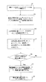
図1は、本発明のある実施例によるスマートアンテナのビーム形成方法を示すフローチャートである。アダプティブスマートアンテナにおいて、通常の基地局が収納できるユーザー数の上限を超過するユーザーが同時に利用可能となった時、ディレイの推定ができない現象を避けるために、本発明は離散ビームを利用して走査する。即ち、所定のセクター内で、スマートアンテナは、アダプティブスマートビームを形成してユーザーをトラックする機能を実現しながら、ビームにて繰り返して走査することにより、ユーザー調査の任務を完成する。
Hereinafter, specific embodiments of the present invention will be described with reference to the drawings.
FIG. 1 is a flowchart illustrating a beam forming method of a smart antenna according to an embodiment of the present invention. In the adaptive smart antenna, in order to avoid the phenomenon that the delay cannot be estimated when users exceeding the upper limit of the number of users that can be accommodated by a normal base station become available at the same time, the present invention scans using a discrete beam. To do. That is, within a given sector, the smart antenna completes the user research mission by repeatedly scanning with the beam while realizing the function of tracking the user by forming an adaptive smart beam.
図1に示すように、まず、ステップ101において、離散ビームを利用してマルチラディウス走査を行う。当該実施例において、単ビームを採用して、予め設定された角度の間隔で離散するように、所定の領域或いはセクター内で、走査を繰り返すことが好ましい。ある位置において希望するユーザーが走査された時、マッチングフィルター方法等を利用して、ディレイの推定を獲得して、それをアダプティブビーム形成の根拠とする。
As shown in FIG. 1, first, in
続いて、ステップ105において、マルチラディウス走査することにより獲得したディレイ情報に基づいて、受信した信号をディレイ調整し、既知の専用制御チャンネルのパイロット記号を基準信号とし、初期重み値を求める。パイロットビットがスペクトラム拡散、スクランブリングされた後の信号を基準信号dとして、アンテナアレイから受信したパイロット信号Xpと基準信号dの相関行列rxd=E[Xpd*]を求める。最小二乗誤差(MMSE)基準により求めたおよその値をアダプティブ初期重み値W=rxdとする。
Subsequently, in
ステップ110において、直前のステップにて算出された初期重み値によって、アレイから受信した信号に対して空間領域処理を行い、サーチされたマルチラディウス情報によって、ユーザーのマルチラディウスディレイ成分が大きいもの毎に対してそれぞれビーム形成を行い、アレイから受信したパイロットタイムセグメント信号に対してビーム形成Yp=WHXpし、アレイから受信した非パイロットタイムセグメント信号に対してビーム形成Yt=WHXtする。
In
次に、ステップ115において、空間領域処理後の信号に対して、逆スクランブル(descrambling)、逆拡散(des-spread)して、専用制御チャンネル情報の獲得を決定する。具体的に、制御部分のパイロットセグメントに対して逆スクランブルし(下記の式(数1)参照)、パイロットセグメントに対して逆拡散する(下記の式(数2)参照)。
Next, in
![]()
![]()

その中、kは何番目の情報記号であるかを表示し、SFは、専用制御チャンネルのスペクトラム拡散因子であり、Sdpch(・)は干渉コードであり、ccch(・)は専用制御チャンネルのスペクトラム拡散コードである。専用物理チャンネルにおいて、制御部分とデータ部分はコード分割多重(code division multiplexing)により送信する。専用物理チャンネルのマルチコード送信を考えない場合、その制御部分のスペクトラム拡散因子はSF=256に固定される。 Among them, k indicates the number of the information symbol, SF is the spread spectrum factor of the dedicated control channel, S dpch (•) is the interference code, and c cch (•) is the dedicated control channel. Spread spectrum code. In the dedicated physical channel, the control part and the data part are transmitted by code division multiplexing. If multi-code transmission of the dedicated physical channel is not considered, the spread spectrum factor of the control part is fixed to SF = 256.
パイロットセグメント情報を利用して逆スクランブルと逆拡散した結果、Rake結合l条目のマルチラディウスの複素数ゲイン(下記の式(数3)参照)、を推定する。 As a result of the descrambling and despreading using the pilot segment information, a multiradius complex gain (see the following equation (3)) of the Rake coupling l-th line is estimated.
その中、qはパイロットビットの数である。チャンネル補償を行い、ユーザーに制御情報を発送して、dcを決定する(下記の式(数4)参照)。上記式中、signは記号判定演算を表示し、imagは虚数部演算を表示する。 Among them, q is the number of pilot bits. Performs channel compensation, and ship the control information to the user, determines a d c (see equation (4) below). In the above formula, sign indicates a symbol determination operation, and imag indicates an imaginary part operation.
![]()
![]()
次に、ステップ120において、専用制御チャンネルの信号対干渉雑音比を計算し、且つ当該信号対干渉雑音比が要求を満たすのかどうかを判定する。当該判定は、獲得した信号対干渉雑音比と所定のしきい値と比べることで完成することができる。例えば、WCDMAシステムにとっては、当該しきい値は4-7dB以下であってもよい。信号対干渉雑音比が当該しきい値を超過した場合は、ステップ125へ進み、そうでない場合は、処理過程はステップ101に戻って、マルチラディウス走査を繰り返す。
Next, in
ステップ125において、専用制御チャンネル情報を再拡散、スクランブリングして、基準信号として、最適化重み値を求める。例えば、WCDMAシステムにおいて、制御部分の時間間隔中の10個記号ビットにおいて、前に有する3乃至8個は既知のパイロット記号である。従って、本発明の一つの実施例の中で、パイロットセグメント時間内で、判定結果の代わりにパイロット記号で再拡散、スクランブリングすることが好ましい。これにより、判定間違いにて発生した消極影響を克服し、重み値が最適重み値になるようにする。非パイロットセグメント時間内で、判定した非パイロットセグメント情報をスペクトラム拡散してからdd(t)=dc(t)cdch(t)、スクランブリングするds(t)=dd(t)Sdpch(t)。その後、新しい基準信号d1=[d・ds]を形成する。制御部分は、ずっとOVSFコードccch=Cch,256,0でスペクトラム拡散するので、当該スペクトラム拡散コードリストの256個データの全てが1である。これは、逆拡散、再拡散計算法の演算の複雑度を低下することに十分に有利である。最後に、新しい基準信号と新しいアレイを利用して信号X1=[Xp・Xt]を受信して、相関行列rxd=E[X1d1*]を計算する。最小二乗誤差(MMSE)基準により最適化重み値Wopt=rxdを求める。
In
最後に、ステップ130において、当該最適化重み値を利用して、ビーム形成して専用データチャンネルに対して処理する。制御部分とデータ部分の空間伝播経路が同じなので、制御部分により更新されて得た重み値は、データ部分に対しても適用される。このようにして、得られた最適化重み値によって対応するデータ情報が求められる。
Finally, in
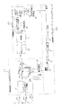
図2は、本発明のある実施例によるスマートアンテナ装置の構造を示す図である。図2に示すように、当該実施例によるスマートアンテナは、複数のアレイ単位(210.1-210.N)からなるアンテナアレイ、空間領域ビーム形成モジュール21、時間領域マッチングフィルターモジュール22、及び再拡散スクランブリングフィードバックモジュール23を含む。上記アンテナアレイ単位(210.1-210.N)は、夫々自分のアンテナ前端(図に示していない)を包括して、無線射周波信号を受信して、受信信号X=[x1,x2,・・・,xN]へと変換するように機能する。これは当該技術分野の技術者にとってはよく知られているものである。
FIG. 2 is a diagram illustrating a structure of a smart antenna device according to an embodiment of the present invention. As shown in FIG. 2, the smart antenna according to this embodiment includes an antenna array composed of a plurality of array units (210.1-210.N), a spatial domain beam forming module 21, a time domain matching
その中で、本発明の実施例によるスマートアンテナに使用されるビーム形成装置が、空間領域ビーム形成モジュール21、時間領域マッチングフィルターモジュール22、及び再拡散スクランブリングフィードバックモジュール23からなる。以下、図面と結合して、本発明の実施例によるスマートアンテナ及びビーム形成装置に対して詳細に説明する。
Among them, the beam forming apparatus used for the smart antenna according to the embodiment of the present invention includes a spatial domain beam forming module 21, a time domain matching
アンテナアレイの受信信号X=[x1,x2,・・・,xN]に対してビーム形成するように、空間領域ビーム形成モジュール21とアンテナアレイ(210.1-210.N)のアレイ単位毎がお互いに接続されている。空間領域ビーム形成モジュール21は、マルチラディウス走査時のディレイ調整ユニット211、重み値推定ユニット212、マルチプライヤ213.1-213.Nとアダー214を包括している。
Received signal X = antenna arrays [x1, x2, ···, xN ] to beamforming with respect to, each array unit of the spatial domain beam forming module 21 and the antenna array (210.1-210.N) are mutually It is connected. The spatial domain beam forming module 21 includes a
マルチラディウス走査時のディレイ調整ユニット211は、離散ビームでマルチラディウス走査を行うのに使用し、ディレイ情報を獲得し、且つアンテナアレイから受信した信号をディレイ調整する。符号分割多元接続システムのスマートアンテナの基地局から受信した時空信号に対してビーム形成する時、最も重要な任務は、異なる経路のディレイを推定するものであり、もし、正確なディレイパラメータがなければ、アダプティブビーム形成を行うことができない。ディレイはビーム形成前に推定する。即ち、ディレイを推定する時、ビームを利用してビーム以外の希望しないユーザーを抑制することができない。利用可能な全てのユーザー(あるセクター)の信号が受信されて、お互いに干渉する。当該問題を根本的に解決するために、本発明は、離散ビームを利用して走査する。即ち、所定のセクター内で、スマートアンテナは、アダプティブスマートビームを形成してユーザーをトラックする機能を実現しながら、ビームにて繰り返し走査することにより、ユーザー調査の任務を完成する。マルチラディウス走査時のディレイ調整ユニット211について、他の図面と併せ、以下で詳細に説明する。
The
ディレイ調整後の信号X=[x1,x2,・・・,xN]は、同時に対応する複数のマルチプライヤ213.1-213.Nと重み値推定ユニット212に伝送される。重み値推定ユニット212は、再拡散スクランブリングフィードバックモジュール23から生成した信号とアンテナアレイから受信した信号X=[x1,x2,・・・,xN]に従って、適当なビーム形成のための重み値w1,w2,・・・,wNを算出する。具体的には、上記基準信号とアンテナアレイの受信信号との相関行列を計算して、最小二乗誤差(MMSE)基準により当該相関行列のおよその値を求めて、重み値とする。マルチプライヤ213.1-213.Nは、夫々対応する重み値w1,w2,・・・,wNにより、乗算を行う。乗算の結果は、アダー214の中で合計されて、ビーム形成の結果として時間領域マッチングフィルターモジュール22に出力される。
The delay-adjusted signal X = [x1, x2,..., XN] is simultaneously transmitted to the corresponding multipliers 213.1 to 213.N and the weight
時間領域マッチングフィルターモジュール22は、逆スクランブルユニット221、逆拡散ユニット222、Rake結合ユニット223、データビット決定ユニット224と信号対干渉雑音比計算決定ユニット225からなる。逆スクランブルユニット221と逆拡散ユニット222は、ビーム形成後の信号に対して逆スクランブル、逆拡散するためのものである。Rake結合ユニットは、複数経路の信号をRake結合するためのものである。データビット決定ユニットはRake結合後の信号に対して、出力伝送したデータを決定するためのものである。信号対干渉雑音比計算決定ユニット225は、決定したデータと受信信号の信号対干渉雑音比を計算するためのものであり、算出した信号対干渉雑音比と予定のしきい値とを比べて要求を満たすのかどうかを判定する。
The time domain matching
再拡散スクランブリングフィードバックモジュール23は、スペクトラム拡散ユニット231とスクランブリングユニット232からなる。信号対干渉雑音比計算決定ユニット225から信号対干渉雑音比が要求を満たすと判定された時、スペクトラム拡散ユニット231とスクランブリングユニット232は、時間領域マッチングフィルターモジュール22は出力決定して得られたデータに対して、スペクトラム拡散、スクランブリングして、基準信号d(k)を生成する。信号対干渉雑音比計算決定ユニット225から信号対干渉雑音比が要求を満たさないことを判定した時、或いは、決定データがない場合、スペクトラム拡散ユニット231とスクランブリングユニット232は、既知の専用制御チャンネルパイロットビットを使用して、スペクトラム拡散とスクランブリングして、基準信号d(k)とする。
The respread scrambling
一つの移動設備ユーザーmを例として、本実施例の動作状況に対して説明する。 The operation situation of the present embodiment will be described by taking one mobile equipment user m as an example.
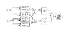
まず、ユーザーmのマルチラディウスディレイ成分が大きいもの毎に対して、それぞれ空間領域ビーム形成モジュール21において、ビーム形成を行う。ユーザーmのl条目のマルチラディウス成分の受信重みベクトルをwm,l=[w1,w2,・・・,wN]Tとし、入力成分x1,x2,・・・,xNと重み成分w1,w2,・・・,wNとをマルチプライヤ213.1、213.2、…213.Nにより対応的に掛け、各マルチプライヤの出力をアダー214に入力して得られたユーザーmのl条目のマルチラディウスのビーム形成器の出力は、式(数5)で示される。 First, beam forming is performed in the spatial region beam forming module 21 for each of the large multi-radius delay components of the user m. The reception weight vector of the multiradius component of the l-th item of user m is w m, l = [w 1 , w 2 ,..., W N ] T , and the input components x 1 , x 2 ,. And weight components w 1 , w 2 ,..., W N correspondingly multiplied by multipliers 213.1, 213.2,... 213.N, and the user m obtained by inputting the output of each multiplier to adder 214 The output of the multiradius beamformer of the 1st row is expressed by the following equation (Equation 5).
ユーザーmのl条目のマルチラディウスの空間領域ビーム形成モジュール21を通した出力を、逆スクランブルユニット221、逆拡散ユニット222の入力として、逆スクランブル、逆拡散する。 The output through the multiradius spatial domain beam forming module 21 of the l-th row of the user m is de-scrambled and de-spread as an input to the de-scramble unit 221 and the de-spread unit 222.
逆拡散ユニット222の出力をパイロット記号がRake結合ユニット223を補助する入力とし、パイロット記号がRake結合ユニット223を補助する場合、パイロット信号を利用して各条のマルチラディウスの複素数振幅を推定する。一つの時間間隔中にq個のパイロット記号を含有すると、希望ユーザーのマルチラディウス信号のパワーは、妨害と雑音の合計より最も大きくなる。パイロット記号を採用して同一時間間隔の非パイロットセグメントデータチャンネルの推定を獲得する簡単な平均推定法を採用して、ユーザーmのl条目のマルチラディウス成分のチャンネルの推定は、式(数7)で示される。
When the output of the despreading unit 222 is used as an input for the pilot symbol to assist the
各マルチラディウス成分のチャンネルの推定により、最大比基準により、相関Rakeの結合を行う。続いて、データビット決定ユニット24において決定する。nをデータビットディジットとすると、ユーザーmの出力を得ることができる。
Correlation Rake is combined based on the maximum ratio criterion by estimating the channel of each multiradius component. Subsequently, the data bit
最後に、信号対干渉雑音比計算決定ユニット225により信号対干渉雑音比のしきい判定を行い、しきい判定の要求を満たすデータビットを再拡散スクランブリングフィードバックモジュール23に入力する。
Finally, the signal-to-interference / noise ratio
制御部分とデータ部分の空間伝播経路が同じなので、そのように更新して得られた重み値はデータ部分にも適用できる。制御部分の毎時間間隔中の10個記号ビットにおいて、前に有する3乃至8個は既知のパイロット記号である。従って、パイロットセグメント時間内で、判定結果のかわりにパイロット記号で再拡散する。これにより、判定間違いにて発生した消極影響を克服し、重み値が最適重み値に接近するようにする。非パイロットタイム内に、あるユーザーの制御部分のn目のビットb(n)が正確に検出されると、ここで、b(n)は検出器の出力であり、このユーザーが時間空間[(n-1)Tb,nTb](Tbはビットサイクルであり、nは正整数である)内の信号波形は、このユーザーの制御部分のスペクトラム拡散コードccch(k)を採用して、再拡散して検出されたデータビットb(n)により得られる。スペクトラム拡散ユニット231とスクランブリングユニット232を通じて、夫々信号対干渉雑音比計算決定ユニット225の出力b(n)及び既知のパイロット記号(234)に対して、スペクトラム拡散とスクランブリングを完成する。コードシートフローを新しい基準信号233として、このユーザーの重み値を調整してビームを形成する。
Since the spatial propagation paths of the control portion and the data portion are the same, the weight value obtained by such update can be applied to the data portion. Of the 10 symbol bits in each time interval of the control part, the 3 to 8 that are preceding are known pilot symbols. Therefore, within the pilot segment time, respreading is performed with pilot symbols instead of determination results. As a result, the negative influence caused by the determination error is overcome, and the weight value approaches the optimum weight value. If the nth bit b (n) of a user's control part is accurately detected within a non-pilot time, then b (n) is the output of the detector and this user is the time space [( n-1) Tb, nTb] (where Tb is a bit cycle and n is a positive integer) is re-spread using the spread spectrum code c cch (k) of this user control part Is obtained by the detected data bit b (n). Through the
初めにユーザーからの信号を受信する時、決定出力b(n)は無い。再拡散スクランブリングフィードバックモジュール23は、既知のパイロット記号を再拡散スクランブリングして、基準信号とする。重み値推定ユニット212は、当該基準信号とアンテナアレイから受信したパイロット信号の相関行列を計算する。最小二乗誤差基準により求めた当該相関行列のおよその値を初期重み値とする。その以外、信号対干渉雑音比計算決定ユニット225から満たさないと判定される場合、再拡散スクランブリングフィードバックモジュール23も、既知のパイロット記号を再拡散スクランブリングして、基準信号とする。重み値推定ユニット212は、当該基準信号とアンテナアレイから受信したパイロット信号の相関行列を再び計算して、最小二乗誤差基準により求めた当該相関行列のおよその値を初期重み値とする。
When receiving a signal from the user for the first time, there is no decision output b (n). The respread scrambling
図3は、本発明のある実施例によるマルチラディウス走査ディレイ調整ユニットの構造を示すフローチャートである。図3に示されるように、ディレイ調整ユニット221は、走査ビーム形成ユニット2110、ディレイサーチャー2112とディレイ調整ユニット2114を含む。
FIG. 3 is a flowchart illustrating the structure of a multiradius scanning delay adjustment unit according to an embodiment of the present invention. As shown in FIG. 3, the delay adjustment unit 221 includes a scanning
アンテナ行列からの受信信号は、ディレイ調整ユニット2114と走査ビーム形成ユニット2110に同時に伝送される。走査ビーム形成ユニット2110は、受信信号に対して走査ビームを形成するためのものであり、そのビーム形成原理は前の説明と基本的に同じである。唯一の違いは、各アレイユニットの重み値が、事前に要求に応じて計算されることである。即ち、それらの既に計算した重み値が単ビームを形成して、所定の領域或いはセクター内で、予め設定された角度の間隔で離散走査する。ディレイサーチャー2112は、走査ビーム形成ユニット2110から形成したビーム信号に対して、マルチラディウスディレイをサーチする。ディレイ調整ユニット2114は、ディレイサーチャー2112からサーチされたマルチラディウスディレイに基づいて、アンテナアレイから受信されたマルチラディウス信号に対してディレイ調整して、対応するマルチプライヤ213.1-213.Nに出力する。
The received signal from the antenna matrix is transmitted to the
図4-6を結合して、ディレイサーチャー2112の構成及びディレイサーチ処理のプロセスに対して説明する。
The configuration of the
図4は受信信号の復調処理を示した。移動局から発射した信号が下記式(数9)で示すものであり、 FIG. 4 shows the demodulation process of the received signal. The signal emitted from the mobile station is shown by the following equation (Equation 9),
![]()
![]()
上記式中、ωcは搬送波周波数であり、Iは同相成分であり、Qは直交成分である。無線空間経路の減衰因子をαと、ディレイをτと、位相偏移φ=ωcτとすると、基地局のアンテナから受信した信号は、下記式(数10)で示すものある。 In the above equation, ω c is a carrier frequency, I is an in-phase component, and Q is a quadrature component. Assuming that the attenuation factor of the radio space path is α, the delay is τ, and the phase shift φ = ω c τ, the signal received from the antenna of the base station is expressed by the following equation (Equation 10).
![]()
![]()
図4で示すように、ラジオ周波数信号SR(t)はまず走査ビーム形成ユニット2110を通じてビーム形成した後、ダウン変換及びローパスフィルターを行う。その中で、
As shown in FIG. 4, the radio frequency signal S R (t) is first beam-formed through the scanning
上記の式(数11)より、ローパスフィルター後、下記式(数12)を得た。 From the above equation (Equation 11), the following equation (Equation 12) was obtained after the low pass filter.
![]()
![]()
同じように、下記式(数13)を得る。 Similarly, the following formula (Formula 13) is obtained.
![]()
![]()
図5は、ディレイサーチャーの構成の一つの例示を示す図である。図6は、コードフィルター構成の一つの例示を示す図である。その中で、TCはタイムサイクルである。コードフィルターは、bitインパルスを基準とし、8倍の過サンプルとし、専用データチャンネル(DPDCH)にスクランブリングする時、長い或いは短いスクランブリングコードのいずれを使用してもよい。レジスタ長をSF*8(SFはスペクトラム拡散因子である)とする。は干渉コードの実部を表示し、SQは干渉コードの虚部を表示する。長い干渉コードにとっては、非サイクルコードフィルターであり、短い干渉コードにとっては、サイクルコードフィルターである。コードフィルターの出力は、制御情報とは関係しているが、トラフィックチャンネル情報とは関係ない。四路コードフィルターの出力は、非相関処理を行った後、夫々(Z12)2と(Z34)2を加えて、ユーザー信号のエネルギー分布が得られる。ピーク値の検出により、ディレイの推定を得られる。異なるディレイのマルチラディウス信号に対しては、複数のピーク値を獲得することができる。ピーク値の高さは、当該ラディウス信号の強さ(即ち、ユーザー信号のエネルギー分布)を表示する。ピーク値が位置しているところにより、当該らディウスのディレイを確定することができる。 FIG. 5 is a diagram illustrating one example of the configuration of the delay searcher. FIG. 6 is a diagram illustrating one example of a code filter configuration. Among them, TC is a time cycle. The code filter is based on the bit impulse and is 8 times oversampled. When scrambling to the dedicated data channel (DPDCH), either a long or short scrambling code may be used. The register length is SF * 8 (SF is a spread spectrum factor). Displays the real part of the interference code, S Q displays the imaginary part of the interference code. For long interference codes, it is a non-cycle code filter, and for short interference codes, it is a cycle code filter. The output of the code filter is related to the control information but not the traffic channel information. The output of the four-way code filter is subjected to decorrelation processing, and then (Z12) 2 and (Z34) 2 are added to obtain the energy distribution of the user signal. Delay estimation can be obtained by detecting the peak value. Multiple peak values can be obtained for multiradius signals with different delays. The height of the peak value indicates the strength of the Radius signal (that is, the energy distribution of the user signal). Depending on where the peak value is located, the Dius delay can be determined.
サーチプロセスに対して説明する。例えば、WCDMA無線マルチラディウスチャンネルにおいて、ユーザーがL経路を利用すると、そのチャンネルの応答は、式(数14)である。 The search process will be described. For example, in the WCDMA wireless multiradius channel, when the user uses the L path, the response of the channel is expressed by the following equation (Equation 14).
![]()
![]()
上記式中、τl、αl、φlは夫々ユーザーのl条目経路のディレイ、減衰因子と位相であり、ディレイサーチはτlに対して推定を行う。マルチラディウス信号は複数の単ラディウスの積み重ね過程であるので、一般性を失うことが無い。単ユーザー且つ単ラディウスで、干渉がない条件で見ると、一般式(数12)と(数13)により、XI(t)とXQ(t)が得られる。以下の処理を行う。 In the above equation, τ l , α l , and φ l are the delay, attenuation factor, and phase of the user's l streak path, respectively, and the delay search estimates for τ l . Since the multiradius signal is a process of stacking a plurality of single radiuses, generality is not lost. X I (t) and X Q (t) can be obtained from the general formulas (Equation 12) and (Equation 13) when viewed with a single user and a single radius and no interference. The following processing is performed.
![]()
![]()
上記式中、SCQ(t)は干渉コードの虚部を表示し、t’は干渉コードのディレイ(t−τ’)を表示し、XI(t)・SCQ(t’)はチャンネル化コードCC(t)の濾過を通じて、分離した制御チャンネルを得ることができる。専用制御チャンネル(DPCCH)のチャンネル化コードの全てが1で、チャンネル化コードの直交性のため、下記式(数16)で示される。 In the above equation, S CQ (t) represents the imaginary part of the interference code, t ′ represents the delay (t−τ ′) of the interference code, and X I (t) · S CQ (t ′) represents the channel. A separate control channel can be obtained through filtration of the activation code C C (t). All of the channelization codes of the dedicated control channel (DPCCH) are 1, and due to the orthogonality of the channelization codes, they are expressed by the following equation (Equation 16).
同じように、 In the same way
もし、コードフィルターから経路がサーチされると、即ち、t’=t−τである時、且つコードフィルター長がG*8chipである時、下記式(数18)である。 If the path is searched from the code filter, that is, when t ′ = t−τ and the code filter length is G * 8 chip, the following equation (Equation 18) is obtained.
![]()
![]()
従って、一般式(数16)と(数17)により、さらに下記のものが得られる。 Therefore, the following can be obtained by the general formulas (Equation 16) and (Equation 17).
上記式中、Tbはビットサイクルであり、bc,nはbcのn目のビットであり、Gはスペクトラム拡散の倍数である。Z1、Z2を結合して、下記(数21)のものを得る。 In the above equation, T b is a bit cycle, b c, n is the nth bit of b c , and G is a multiple of spread spectrum. Z1 and Z2 are combined to obtain the following (Equation 21).
![]()
![]()
同じように、 In the same way
![]()
![]()
そこで、それぞれ(Z12)2と(Z34)2を加えて、ユーザー信号のエネルギー分布を得ることができる。ピーク値の検出により、ディレイτの推定を獲得する。 Therefore, the energy distribution of the user signal can be obtained by adding (Z12) 2 and (Z34) 2, respectively. An estimate of the delay τ is obtained by detecting the peak value.
理想的な状態において、t’=t−τであると、コードフィルターから得たZ値は0より大きい。t’≠t−τである時、コードフィルターから得たZ値はいつでも0である。このような場合、0ではないZ値の位置だけをサーチすれば、ディレイを確定することができる。しかしながら、干渉コードの自己相関性と相互相関性がまだ理想的ではないし、それに雑音の影響及び過サンプルに加えているため、Z値がt’≠t−τである時、大きいピーク値(ピークと簡称する)が出現することもある。これは、ディレイの推定に一定の問題と難度を招いた。ディレイを正確に推定するには、二つの問題を解決すべきある。一つは、偽ピークを除去するように、ピーク値のしきいを合理的に確定すること、もう一つは、ディレイを正確に推定する目的に達するように、ピーク値がしきいを超過する複数のZ値の中で、真ピーク値の位置を検出することである。 In an ideal state, if t ′ = t−τ, the Z value obtained from the code filter is greater than zero. When t ′ ≠ t−τ, the Z value obtained from the code filter is always zero. In such a case, the delay can be determined by searching only the position of the non-zero Z value. However, since the autocorrelation and cross-correlation of the interference code are not yet ideal and add to the influence of noise and oversampling, when the Z value is t ′ ≠ t−τ, a large peak value (peak May simply appear). This has led to certain problems and difficulty in delay estimation. To accurately estimate the delay, two problems should be solved. One is to reasonably establish the threshold of the peak value so as to eliminate false peaks, and the other is that the peak value exceeds the threshold to reach the purpose of accurately estimating the delay. It is to detect the position of the true peak value among a plurality of Z values.
本実施例において、Z値がフィルターする前の受信した全ての信号の平均パワーの4倍より大きい値をピーク値のしきいδとする。ピーク値検出において、最大値より左側の傾斜度は0より大きい、右側の傾斜度は0より小さい。ピーク値しきいの検出は下記の重要な部分から構成する。
(1) ピーク値の粗選択
Z値中において、ピーク値しきいより大きい点を予備ピーク値点として下記の式(数25)により設定する。
In this embodiment, the peak value threshold δ is a value that is greater than four times the average power of all received signals before the Z value is filtered. In peak value detection, the slope on the left side of the maximum value is greater than 0, and the slope on the right side is less than 0. The detection of the peak value threshold consists of the following important parts.
(1) Rough selection of peak value In the Z value, a point larger than the peak value threshold is set as a preliminary peak value point according to the following equation (Equation 25).
(数25)
![]()
![]()
Pは可能ピーク値点の集合であり、単位は1/8chipである。選択した予備ピーク値の中で、ピーク値点ではなく更に処理が行われるべき真ピーク付近の点を含むこともある。
(2)ピークを選択する前の前処理
ピークを選択する前に、左側の傾斜度の記号関数Dl(k)は、式(数26)で示される。
P is a set of possible peak value points, and the unit is 1/8 chip. Among the selected preliminary peak values, not the peak value points but also points near the true peak to be processed may be included.
(2) Before selecting a pre-processing peak before selecting a peak, the symbol function D l (k) of the left slope is expressed by Equation (Equation 26).
![]()
![]()
また、右側の傾斜度の記号関数Dr(k): Also, the symbol function D r (k) of the right slope:
![]()
![]()
(3)ピーク識別ロジック
ピークの特性により、上記前処理の基づいて、ビーク識別ロジックを容易に得られる。kがピーク値点である場合、
(3) Peak identification logic Based on the characteristics of the peak, the beak identification logic can be obtained easily. If k is the peak value point,
![]()
![]()
しかし、非ピーク値点である場合、 However, if it is a non-peak point,
![]()
![]()
一般式(数29)を満たす点の集合を検出して、1/8chipの持続時間を掛けると、要求するディレイτl(l=1,2,3,・・・,L)となり、Lは検出できる経路の数を表示する。 When a set of points satisfying the general formula (Equation 29) is detected and multiplied by the duration of 1/8 chip, the required delay τ l (l = 1, 2, 3,..., L) is obtained. Displays the number of paths that can be detected.
以上の本発明のスマートアンテナのビーム形成装置をなす各構成部分はハードウェアモジュールでも良く、ソフトフェアモジュールでも良い。それらのモジュールを専用チップ或いはFPGA中に配置しても良い。一部分のモジュールをDSPの中で、ソフトウェアで実現しても良い。 Each component constituting the smart antenna beam forming apparatus of the present invention may be a hardware module or a software module. Those modules may be arranged in a dedicated chip or FPGA. Some modules may be implemented by software in the DSP.
図7は、本発明の一つの実施例によるスマートアンテナの空間配置を示した。現在のところ、セルプロット内で指向性アンテナが多く採用されており、各プロットは三つのセクターに分けられている。図7で示す本発明の実施例において、アンテナアレイは三組の均一なラインアレイ(line array)ユニットからなる。即ち、第一組が3.101、3.102、3.103、3.104であり、第二組が3.201、3.202、3.203、3.204及び第三組が3.301、3.302、3.303、3.304である。各組のアンテナは120度範囲の空間を走査する。そのような走査は時間がかかりない、一つのセクターが120度であるため、アンテナアレイユニットの数は4である。その場合、波ローブの最小幅は25.25度ある。離散ビームの走査角度の間隔が25度である場合、一回の走査を完成するには、5回のビーム角度変換のみ必要とする。 FIG. 7 shows a spatial arrangement of smart antennas according to one embodiment of the present invention. Currently, many directional antennas are used in cell plots, and each plot is divided into three sectors. In the embodiment of the present invention shown in FIG. 7, the antenna array consists of three sets of uniform line array units. That is, the first set is 3.101, 3.102, 3.103, 3.104, the second set is 3.201, 3.202, 3.203, 3.204, and the third set is 3.301, 3.302, 3.303, 3.304. Each set of antennas scans a space in the 120 degree range. Such scanning does not take time, the number of antenna array units is 4 because one sector is 120 degrees. In that case, the minimum width of the wave lobe is 25.25 degrees. When the interval between the scan angles of the discrete beams is 25 degrees, only five beam angle conversions are required to complete one scan.
図8と図9は、本発明の実施例による入力―出力の信号対干渉雑音比の曲線図である。実験のシミュレーション条件は、4アレイユニットの均一なラインアレイで20個のユーザーで、各ユーザーは4条の強度が同じJackエクリプスマルチラディウスを有する。その中で、図8で示すものは、本発明の実施例によるスマートアンテナが、マクロ(Macro)において、20個のユーザー、20フレームデータ長、記号速度60kbit/s、移動局速度が30km/hである環境でのデータチャンネルの出力SINRである。横座標Eb/N0は信号対雑音比を表示し、変化範囲は4〜12dBであり、間隔は2dBである。図面から分かるように、入力信号対雑音比が8dBである場合、本発明の出力信号対雑音比は8.7dBに接近している。ビーム走査がない方法の出力信号雑音比はおよそ5.3dBである。3.5dBの差がある。出力信号対雑音比が4、6、10と12dBである時、結果は類似している。従って、本発明方法を採用した後、出力信号対雑音比が向上したということが分かる。
8 and 9 are curve diagrams of the input-output signal-to-interference noise ratio according to an embodiment of the present invention. The simulation conditions for the experiment are 20 users with a uniform line array of 4 array units, each user having a Jack Eclipse Multiradius with the same 4 strand strength. Among them, a smart antenna according to an embodiment of the present invention is shown in FIG. 8, in a macro, 20 users, 20 frame data length, symbol speed 60 kbit / s,
図9に示したものは、本発明の実施例によるスマートアンテナが、マクロプロットにおいて、20個のユーザー、記号速度60 kbit/s、移動局速度が240km/hである環境でのデータチャンネルの出力SINRである。横座標Eb/N0は入力信号対雑音比を表示し、変化範囲は4〜12dBであり、間隔は2dBである。入力信号対雑音比が8dBである場合、本発明の出力信号対雑音比は5.6dBに接近している。ビーム走査がない方法の出力信号雑音比はおよそ0.9dBである。4.7dBの差がある。入力信号対雑音比が4、6、10と12dBである時、結果は類似している。従って、本発明方法を採用することによって、出力信号対雑音比が向上した。 FIG. 9 shows the output of a data channel in an environment where a smart antenna according to an embodiment of the present invention has 20 users, a symbol speed of 60 kbit / s, and a mobile station speed of 240 km / h in a macro plot. SINR. The abscissa Eb / N0 represents the input signal-to-noise ratio, the change range is 4-12 dB, and the interval is 2 dB. When the input signal to noise ratio is 8 dB, the output signal to noise ratio of the present invention is close to 5.6 dB. The output signal-to-noise ratio of the method without beam scanning is approximately 0.9 dB. There is a difference of 4.7dB. The results are similar when the input signal to noise ratio is 4, 6, 10 and 12 dB. Therefore, the output signal-to-noise ratio was improved by employing the method of the present invention.
以上のとおり、本発明の実施例により本発明について説明したが、以上の実施例は全部の実施例ではない。当該技術分野の技術者は、本発明の主旨と範囲内でいろいろな変化と改良をおこなうことができる。例えば、以上はWCDMAシステムに対して説明したが、当該技術分野の技術者は、他のコード分割多重システムにも適用できるということを理解できる。従って、本発明は上記実施例に限定されず、添付した特許請求の範囲を基準とする。 As described above, the present invention has been described based on the embodiments of the present invention, but the above embodiments are not all embodiments. Those skilled in the art can make various changes and improvements within the spirit and scope of the present invention. For example, while the above has been described for a WCDMA system, those skilled in the art can appreciate that it is applicable to other code division multiplexing systems. Accordingly, the present invention is not limited to the above embodiments, but is based on the appended claims.
21・・・・空間領域ビーム形成モジュール
211・・・マルチラディウス走査ディレイ調整
212・・・重み値推定ユニット
22・・・・時間領域マッチングフィルタモジュール
221・・・逆スクランブルユニット
222・・・逆拡散ユニット
223・・・Rake結合ユニット
224・・・データビット決定ユニット
23・・・・再拡散スクランブリングフィードバックモジュール
231・・・スペクトラム拡散
232・・・スクランブリング
21 ... Spatial domain
Claims (11)
前記マルチラディウスディレイ情報によって、受信信号に対してディレイ調整し、
専用制御チャンネルのパイロット信号を基準信号として、既知の専用制御チャンネルのパイロットビットに対して、スペクトラム拡散、スクランブリングし、
前記スペクトラム拡散、スクランブリングして得られたパイロット信号とアンテナアレイから受信したパイロット信号の相関行列を計算し;
最小二乗誤差基準により、求めた当該相関行列のおよその値を、初期重み値とし、
前記初期重み値を利用して、アレイから受信した信号に対して、空間領域処理を行い、
前記空間領域処理後の信号により、専用制御チャンネル情報の判定出力を獲得し、
専用制御チャンネルのパイロットセグメント時間内で、判定結果の代わりにパイロット記号で再拡散、スクランブリングし、
専用制御チャンネルの非パイロットセグメント時間内で、データの全てが1であるスペクトラム拡散コードリストを用いて、判定した非パイロットセグメント情報をスペクトラム拡散してから、スクランブリングして、新しい基準信号を形成し、
前記新しい基準信号と新しい受信信号との相関行列を計算し、
最小二乗誤差基準により最適化重み値を求め、
前記最適化重みにより、アダプティブビームを形成して、専用データチャンネル情報を処理することを含むスマートアンテナのビーム形成方法。Using a single beam formed with a weight value calculated according to a prior request, multiradius scanning is performed in a predetermined area so as to be dispersed at a predetermined angular interval and width, or one or When a desired user is found at a plurality of scanning angles, the scanning angle is recorded, a multiradius delay corresponding to the scanning angle is calculated to obtain multiradius delay information,
By the multiradius delay information, delay adjustment for the received signal,
Using the pilot signal of the dedicated control channel as a reference signal, spread spectrum and scrambling the pilot bits of the known dedicated control channel,
Calculating a correlation matrix between the pilot signal obtained by the spread spectrum and scrambling and the pilot signal received from the antenna array;
Based on the least square error criterion, the approximate value of the correlation matrix obtained is used as the initial weight value,
Using the initial weight value, spatial domain processing is performed on signals received from the array,
The determination output of the dedicated control channel information is obtained by the signal after the spatial domain processing,
Within the pilot segment time of the dedicated control channel, respreading and scrambling with pilot symbols instead of decision results,
Spread spectrum of the determined non-pilot segment information using a spread spectrum code list in which all data is 1 within the non-pilot segment time of the dedicated control channel, and then scramble to form a new reference signal. ,
Calculating a correlation matrix between the new reference signal and the new received signal;
Find the optimization weight value according to the least square error criterion,
A beam forming method for a smart antenna, comprising: forming an adaptive beam with the optimization weight to process dedicated data channel information .
前記パイロットタイムセグメントのビーム形成信号に対して、逆拡散と逆スクランブルを行う;及び、
当該逆スクランブルと逆拡散した結果を使用して複素数ゲインを推定して、制御部分の非パイロットセグメント信号に対して決定することを含むことを特徴とする請求項1に記載のビーム形成方法。In the step of obtaining a decision output of the dedicated control channel information,
Despreading and descrambling the beamforming signal of the pilot time segment; and
The beamforming method according to claim 1 , further comprising: estimating a complex gain using a result of the descrambling and despreading and determining a non-pilot segment signal of a control portion.
再拡散スクランブリングフィードバックモジュールからフィードバックした基準信号により、ビーム形成するための複数の重み値を計算する重み値推定ユニット;
アンテナアレイから受信した信号に対してビーム形成を行うための空間領域ビーム形成モジュール;
前記空間領域ビーム形成モジュールによりビーム形成した信号によって、転送したデータを獲得するための時間領域マッチングフィルターモジュール;及び、
前記時間領域マッチングフィルターモジュールから獲得したデータ情報によって、基準信号を生成して、前記空間領域ビーム形成モジュールにフィードバックして、空間領域処理後の信号により、専用制御チャンネル情報の判定出力を獲得し、前記専用制御チャンネルのパ イロットセグメント時間内で、判定結果の代わりにパイロット記号で再拡散、スクランブリングし、前記専用制御チャンネルの非パイロットセグメント時間内で、データの全てが1であるスペクトラム拡散コードリストを用いて、判定した非パイロットセグメント情報をスペクトラム拡散してから、スクランブリングして、新しい基準信号を形成するための再拡散スクランブリングフィードバックモジュールを含み、
前記重み値推定ユニットが、前記基準信号とアンテナアレイから受信した信号の相関行列を計算して、最小二乗誤差基準により求めた当該相関行列のおよその値を前記重み値とし、
伝送したデータを獲得しなかった場合、再拡散スクランブリングフィードバックモジュールが、既知の専用制御チャンネルのパイロットビットを使用して、スペクトラム拡散、スクランブリングして、基準信号とし、前記重み値推定ユニットが、前記基準信号とアンテナアレイから受信した信号の相関行列を計算して、最小二乗誤差基準により求めた当該相関行列のおよその値を前記重み値とすることを特徴とするスマートアンテナのビーム形成装置。A multi-radius is used to obtain delay information by performing multi-radius scanning in a predetermined area so as to be discrete at a predetermined angular interval and width using a single beam, and to delay-adjust signals received from the antenna array. A Radius scan delay adjustment unit,
A weight value estimation unit for calculating a plurality of weight values for beam forming according to the reference signal fed back from the respreading scrambling feedback module;
A spatial domain beamforming module for beamforming the signals received from the antenna array;
A time domain matching filter module for acquiring transferred data according to a signal beamformed by the spatial domain beamforming module; and
A reference signal is generated according to data information acquired from the time domain matching filter module, fed back to the spatial domain beam forming module, and a determination output of dedicated control channel information is acquired by a signal after spatial domain processing, The dedicated control channel Re-spreading and scrambling with pilot symbols instead of determination results within the pilot segment time, and determination using a spread spectrum code list in which all of the data is 1 within the non-pilot segment time of the dedicated control channel Including a respread scrambling feedback module for spread spectrum non-pilot segment information and then scrambling to form a new reference signal ;
The weight value estimation unit calculates a correlation matrix between the reference signal and a signal received from an antenna array, and sets an approximate value of the correlation matrix obtained by a least square error criterion as the weight value,
If the transmitted data is not acquired, the respreading scrambling feedback module uses the pilot bits of the known dedicated control channel to perform spread spectrum, scrambling to obtain a reference signal, and the weight value estimation unit A beam forming apparatus for a smart antenna, wherein a correlation matrix between the reference signal and a signal received from an antenna array is calculated, and an approximate value of the correlation matrix obtained by a least square error criterion is used as the weight value.
所定角度間隔、所定幅にて離散走査ビームを形成するための走査ビーム形成ユニット;
前記走査ビーム形成ユニットから形成した走査ビームにて、マルチラディウスディレイをサーチするためのディレイサーチャー;及び
前記ディレイサーチャーからサーチされたマルチラディウスディレイにより、アンテナアレイから受信したマルチラディウス信号をディレイ調整するディレイ調整ユニットを含むことを特徴とする請求項6に記載のビーム形成装置。The multi-radius scanning delay adjustment unit includes:
A scanning beam forming unit for forming a discrete scanning beam at a predetermined angular interval and a predetermined width;
A delay searcher for searching for a multiradius delay in the scanning beam formed from the scanning beam forming unit; and a delay for adjusting the delay of the multiradius signal received from the antenna array by the multiradius delay searched from the delay searcher. The beam forming apparatus according to claim 6 , further comprising an adjustment unit.
前記重み値推定ユニットから計算した対応重み値と対応アンテナアレイのアレイユニットから受信した信号をそれぞれ掛けるための複数のマルチプライヤ;及び、
複数のマルチプライヤの出力を加えるためのアダーを含むことを特徴とする請求項6に記載のビーム形成装置。The spatial domain beamforming module further comprises:
A plurality of multipliers each for multiplying the corresponding weight value calculated from the weight value estimation unit and the signal received from the array unit of the corresponding antenna array; and
The beam forming apparatus according to claim 6 , further comprising an adder for adding outputs of a plurality of multipliers.
前記空間領域ビーム形成モジュールからビーム形成した信号に対して、逆スクランブル、逆拡散するための逆スクランブル、逆拡散ユニット;
複数経路の信号に対してRake結合するためのRake結合ユニット;及び、
Rake結合後の信号に対して、出力伝送したデータを決定するためのデータビット決定ユニットを含むことを特徴とする請求項6に記載のビーム形成装置。The time domain matching filter module includes:
Descramble and despread unit for descramble and despread the signal beamformed from the spatial domain beamforming module;
A Rake coupling unit for Rake coupling to multi-path signals; and
The beam forming apparatus according to claim 6 , further comprising a data bit determining unit for determining data transmitted and transmitted with respect to the signal after Rake combination.
前記時間領域マッチングフィルターモジュールから獲得した伝送データに対して、再拡散スクランブリングして、基準信号とするための再拡散スクランブリングユニットを含むことを特徴とする請求項6に記載のビーム形成装置。The respread scrambling feedback module includes:
The beam forming apparatus according to claim 6 , further comprising a respreading scrambling unit for respreading the transmission data acquired from the time domain matching filter module to obtain a reference signal.
Applications Claiming Priority (2)
| Application Number | Priority Date | Filing Date | Title |
|---|---|---|---|
| CNA021372381A CN1486106A (en) | 2002-09-24 | 2002-09-24 | Apparatus and method for selfadaptive beam forming of intelligent antenna |
| PCT/CN2002/000946 WO2004030239A1 (en) | 2002-09-24 | 2002-12-31 | A smart antenna and a method and a device for forming beam of the smart antenna |
Publications (2)
| Publication Number | Publication Date |
|---|---|
| JP2006500834A JP2006500834A (en) | 2006-01-05 |
| JP4183134B2 true JP4183134B2 (en) | 2008-11-19 |
Family
ID=32034731
Family Applications (1)
| Application Number | Title | Priority Date | Filing Date |
|---|---|---|---|
| JP2004538647A Expired - Fee Related JP4183134B2 (en) | 2002-09-24 | 2002-12-31 | Smart antenna and beam forming method and apparatus thereof |
Country Status (6)
| Country | Link |
|---|---|
| EP (1) | EP1545023B1 (en) |
| JP (1) | JP4183134B2 (en) |
| KR (1) | KR100770498B1 (en) |
| CN (1) | CN1486106A (en) |
| AU (1) | AU2002357571A1 (en) |
| WO (1) | WO2004030239A1 (en) |
Families Citing this family (13)
| Publication number | Priority date | Publication date | Assignee | Title |
|---|---|---|---|---|
| WO2004059793A1 (en) * | 2002-12-31 | 2004-07-15 | Zte Corporation | Smart antenna, method and device for forming |
| CN101084633B (en) * | 2004-12-17 | 2011-05-18 | 华为技术有限公司 | Multipath searcher, refinement treatment unit and method for direction of arrival estimation using multipath searcher |
| CN100499398C (en) | 2005-03-02 | 2009-06-10 | 中兴通讯股份有限公司 | Method and apparatus for realizing intelligent antenna of broadband CDMA system |
| US20090190544A1 (en) * | 2008-01-25 | 2009-07-30 | Qualcomm Incorporated | Method and apparatus for channel identification in a wireless communication system |
| ATE474382T1 (en) * | 2008-05-16 | 2010-07-15 | Alcatel Lucent | SEMI-STATIC JET FORMING METHOD AND APPARATUS |
| CN101515816B (en) * | 2009-04-02 | 2012-12-12 | 重庆航天火箭电子技术有限公司 | Self-adapting subgroup precoding method of maximal SJNR criterion |
| US7994982B2 (en) | 2009-06-12 | 2011-08-09 | Raytheon Company | Method and apparatus for bounded time delay estimation |
| CN105375963A (en) * | 2014-08-27 | 2016-03-02 | 上海贝尔股份有限公司 | Radiation diagram configurable antenna for micro cell base station |
| US9578644B2 (en) * | 2014-09-26 | 2017-02-21 | Mediatek Inc. | Beam misalignment detection for wireless communication system with beamforming |
| CN108293194B (en) * | 2015-10-02 | 2021-07-16 | 瑞典爱立信有限公司 | Adaptive beamforming scanning |
| CN105227227B (en) * | 2015-10-15 | 2018-10-12 | 宿州学院 | A kind of intelligent antenna beam formation system and method based on small echo |
| CN111694023A (en) * | 2020-06-08 | 2020-09-22 | 西安交通大学 | Satellite navigation anti-interference receiving processing method based on despreading and despreading |
| CN113572523B (en) * | 2021-07-27 | 2022-05-13 | 华中科技大学 | Online intrinsic and signal relative transmission delay estimation method for homologous coherent system |
Family Cites Families (9)
| Publication number | Priority date | Publication date | Assignee | Title |
|---|---|---|---|---|
| GB2281010B (en) * | 1993-08-12 | 1998-04-15 | Northern Telecom Ltd | Base station antenna arrangement |
| JP3328930B2 (en) * | 1998-02-13 | 2002-09-30 | 日本電気株式会社 | Adaptive receiver |
| JP3092798B2 (en) | 1998-06-30 | 2000-09-25 | 日本電気株式会社 | Adaptive transceiver |
| WO2000051364A2 (en) * | 1999-02-26 | 2000-08-31 | Telefonaktiebolaget Lm Ericsson (Publ) | Method for antenna gain acquisition in a cellular system |
| US6177906B1 (en) | 1999-04-01 | 2001-01-23 | Arraycomm, Inc. | Multimode iterative adaptive smart antenna processing method and apparatus |
| JP3424659B2 (en) | 2000-06-02 | 2003-07-07 | 日本電気株式会社 | Multi-beam receiver |
| CN1139192C (en) * | 2000-12-14 | 2004-02-18 | 华为技术有限公司 | Adaptive array up receiving method and receiving for radio communication system |
| JP2002262328A (en) * | 2000-12-25 | 2002-09-13 | Toshiba Corp | Mobile communication terminal |
| JP3877522B2 (en) * | 2000-12-28 | 2007-02-07 | 日本無線株式会社 | Wireless communication system |
-
2002
- 2002-09-24 CN CNA021372381A patent/CN1486106A/en active Pending
- 2002-12-31 WO PCT/CN2002/000946 patent/WO2004030239A1/en active Application Filing
- 2002-12-31 EP EP02807856.6A patent/EP1545023B1/en not_active Expired - Fee Related
- 2002-12-31 JP JP2004538647A patent/JP4183134B2/en not_active Expired - Fee Related
- 2002-12-31 KR KR20057005011A patent/KR100770498B1/en active IP Right Grant
- 2002-12-31 AU AU2002357571A patent/AU2002357571A1/en not_active Abandoned
Also Published As
| Publication number | Publication date |
|---|---|
| AU2002357571A1 (en) | 2004-04-19 |
| EP1545023A4 (en) | 2009-07-15 |
| CN1486106A (en) | 2004-03-31 |
| KR100770498B1 (en) | 2007-10-25 |
| JP2006500834A (en) | 2006-01-05 |
| EP1545023A1 (en) | 2005-06-22 |
| EP1545023B1 (en) | 2016-09-07 |
| WO2004030239A1 (en) | 2004-04-08 |
| KR20050057562A (en) | 2005-06-16 |
Similar Documents
| Publication | Publication Date | Title |
|---|---|---|
| US6347234B1 (en) | Practical space-time radio method for CDMA communication capacity enhancement | |
| EP1858175B1 (en) | A method and equipment for realizing smart antenna in wcdma system | |
| JP4421106B2 (en) | Practical space-time radio method for improving CDMA communication capacity | |
| KR100428709B1 (en) | Apparatus for Forward Beamforming using Feedback of Multipath Information and Method Thereof | |
| US7043275B2 (en) | Radio communication apparatus using adaptive antenna | |
| KR100735813B1 (en) | Method of generating weighted vector in the development of smart antennas for IMT-2000 CDMA wireless communication | |
| US8515355B2 (en) | Method of realizing smart antenna based on software radio and system therefor | |
| US20030069047A1 (en) | Adaptive array antenna directivity control system | |
| JP4183134B2 (en) | Smart antenna and beam forming method and apparatus thereof | |
| JP2003264501A (en) | Adaptive antenna base station device | |
| Chen et al. | Joint angle and delay estimation for DS-CDMA with application to reduced dimension space-time RAKE receivers | |
| US7006042B2 (en) | Antenna array system, method of controlling the directivity pattern thereof, and mobile terminal | |
| JP3856126B2 (en) | Path timing detection method, path timing detection apparatus, and adaptive array antenna system | |
| CN1549473B (en) | Beam forming method adapted to wide band CDMA system | |
| CN100429826C (en) | Smart antenna and its method and device for forming self adaptive beam | |
| WO1998008319A9 (en) | Rake receiver for spread spectrum signal demodulation | |
| CN100433594C (en) | Adaptive beamforming method in wideband code division multiple access system | |
| KR100329110B1 (en) | Space-Time Array Receive System Using Chip-Level, Time-Reference Beamforming Algorithm | |
| CN102006114B (en) | Intelligent antenna system and spread-spectrum signal receiver | |
| CN101133659B (en) | Intelligent antenna implementing method based on software radio and implement system thereof | |
| Zahid | Space-time Processsing for the Wideband-CDMA System | |
| RU2289203C2 (en) | Signal transfer method (variants) and device for realization thereof (variants) | |
| Tong et al. | A method to improve post-despread adaptive antenna array | |
| JP2004357315A (en) | Adaptive array antenna directivity control system | |
| KR20040043894A (en) | System for base station receiving of CDMA and method thereof |
Legal Events
| Date | Code | Title | Description |
|---|---|---|---|
| A977 | Report on retrieval |
Free format text: JAPANESE INTERMEDIATE CODE: A971007 Effective date: 20070810 |
|
| A131 | Notification of reasons for refusal |
Free format text: JAPANESE INTERMEDIATE CODE: A131 Effective date: 20070815 |
|
| A521 | Written amendment |
Free format text: JAPANESE INTERMEDIATE CODE: A523 Effective date: 20071107 |
|
| A131 | Notification of reasons for refusal |
Free format text: JAPANESE INTERMEDIATE CODE: A131 Effective date: 20071217 |
|
| A521 | Written amendment |
Free format text: JAPANESE INTERMEDIATE CODE: A523 Effective date: 20080313 |
|
| A131 | Notification of reasons for refusal |
Free format text: JAPANESE INTERMEDIATE CODE: A131 Effective date: 20080414 |
|
| A521 | Written amendment |
Free format text: JAPANESE INTERMEDIATE CODE: A523 Effective date: 20080714 |
|
| TRDD | Decision of grant or rejection written | ||
| A01 | Written decision to grant a patent or to grant a registration (utility model) |
Free format text: JAPANESE INTERMEDIATE CODE: A01 Effective date: 20080811 |
|
| A01 | Written decision to grant a patent or to grant a registration (utility model) |
Free format text: JAPANESE INTERMEDIATE CODE: A01 |
|
| A61 | First payment of annual fees (during grant procedure) |
Free format text: JAPANESE INTERMEDIATE CODE: A61 Effective date: 20080828 |
|
| FPAY | Renewal fee payment (event date is renewal date of database) |
Free format text: PAYMENT UNTIL: 20110912 Year of fee payment: 3 |
|
| R150 | Certificate of patent or registration of utility model |
Ref document number: 4183134 Country of ref document: JP Free format text: JAPANESE INTERMEDIATE CODE: R150 Free format text: JAPANESE INTERMEDIATE CODE: R150 |
|
| FPAY | Renewal fee payment (event date is renewal date of database) |
Free format text: PAYMENT UNTIL: 20110912 Year of fee payment: 3 |
|
| FPAY | Renewal fee payment (event date is renewal date of database) |
Free format text: PAYMENT UNTIL: 20120912 Year of fee payment: 4 |
|
| R250 | Receipt of annual fees |
Free format text: JAPANESE INTERMEDIATE CODE: R250 |
|
| FPAY | Renewal fee payment (event date is renewal date of database) |
Free format text: PAYMENT UNTIL: 20130912 Year of fee payment: 5 |
|
| R250 | Receipt of annual fees |
Free format text: JAPANESE INTERMEDIATE CODE: R250 |
|
| R250 | Receipt of annual fees |
Free format text: JAPANESE INTERMEDIATE CODE: R250 |
|
| R250 | Receipt of annual fees |
Free format text: JAPANESE INTERMEDIATE CODE: R250 |
|
| R250 | Receipt of annual fees |
Free format text: JAPANESE INTERMEDIATE CODE: R250 |
|
| R250 | Receipt of annual fees |
Free format text: JAPANESE INTERMEDIATE CODE: R250 |
|
| R250 | Receipt of annual fees |
Free format text: JAPANESE INTERMEDIATE CODE: R250 |
|
| R250 | Receipt of annual fees |
Free format text: JAPANESE INTERMEDIATE CODE: R250 |
|
| R250 | Receipt of annual fees |
Free format text: JAPANESE INTERMEDIATE CODE: R250 |
|
| LAPS | Cancellation because of no payment of annual fees |