EP1190898A1 - Ladebordwandsystem mit Unterfahrschutz - Google Patents
Ladebordwandsystem mit Unterfahrschutz Download PDFInfo
- Publication number
- EP1190898A1 EP1190898A1 EP00120658A EP00120658A EP1190898A1 EP 1190898 A1 EP1190898 A1 EP 1190898A1 EP 00120658 A EP00120658 A EP 00120658A EP 00120658 A EP00120658 A EP 00120658A EP 1190898 A1 EP1190898 A1 EP 1190898A1
- Authority
- EP
- European Patent Office
- Prior art keywords
- vehicle
- actuator
- tailgate system
- lifting
- arm
- Prior art date
- Legal status (The legal status is an assumption and is not a legal conclusion. Google has not performed a legal analysis and makes no representation as to the accuracy of the status listed.)
- Withdrawn
Links
Images


Classifications
-
- B—PERFORMING OPERATIONS; TRANSPORTING
- B60—VEHICLES IN GENERAL
- B60P—VEHICLES ADAPTED FOR LOAD TRANSPORTATION OR TO TRANSPORT, TO CARRY, OR TO COMPRISE SPECIAL LOADS OR OBJECTS
- B60P1/00—Vehicles predominantly for transporting loads and modified to facilitate loading, consolidating the load, or unloading
- B60P1/44—Vehicles predominantly for transporting loads and modified to facilitate loading, consolidating the load, or unloading having a loading platform thereon raising the load to the level of the load-transporting element
-
- B—PERFORMING OPERATIONS; TRANSPORTING
- B60—VEHICLES IN GENERAL
- B60R—VEHICLES, VEHICLE FITTINGS, OR VEHICLE PARTS, NOT OTHERWISE PROVIDED FOR
- B60R19/00—Wheel guards; Radiator guards, e.g. grilles; Obstruction removers; Fittings damping bouncing force in collisions
- B60R19/56—Fittings damping bouncing force in truck collisions, e.g. bumpers; Arrangements on high-riding vehicles, e.g. lorries, for preventing vehicles or objects from running thereunder
-
- B—PERFORMING OPERATIONS; TRANSPORTING
- B60—VEHICLES IN GENERAL
- B60R—VEHICLES, VEHICLE FITTINGS, OR VEHICLE PARTS, NOT OTHERWISE PROVIDED FOR
- B60R19/00—Wheel guards; Radiator guards, e.g. grilles; Obstruction removers; Fittings damping bouncing force in collisions
- B60R19/02—Bumpers, i.e. impact receiving or absorbing members for protecting vehicles or fending off blows from other vehicles or objects
- B60R19/24—Arrangements for mounting bumpers on vehicles
- B60R19/38—Arrangements for mounting bumpers on vehicles adjustably or movably mounted, e.g. horizontally displaceable for securing a space between parked vehicles
-
- B—PERFORMING OPERATIONS; TRANSPORTING
- B60—VEHICLES IN GENERAL
- B60R—VEHICLES, VEHICLE FITTINGS, OR VEHICLE PARTS, NOT OTHERWISE PROVIDED FOR
- B60R21/00—Arrangements or fittings on vehicles for protecting or preventing injuries to occupants or pedestrians in case of accidents or other traffic risks
- B60R2021/0002—Type of accident
- B60R2021/0011—Rear collision or recoiling bounce after frontal collision
Definitions
- the invention relates to a tail lift system for Attachment to a vehicle, including a loading platform, by means of a stroke actuator attached to the vehicle between an upper and a lower position swinging back and forth, and a relative underride protection that can be swiveled to the vehicle.
- a tail lift system of this type is known (EP-A-0 941 896).
- the Underrun protection attached to a lifting arm with a Stroke actuator together forms the lifting device, wherein the underrun protection on the lifting device below is appropriate and with this procedure, because the underride guard itself on the lifting arm of the lifting device is movably mounted, the height of the lifting arm should change during the movement of the lifting device.
- lifting arm there The fixed geometric connection between the lifting arm (called lifting arm there) and the underride guard causes an automatic movement of the underrun protection whenever the lifting device moves becomes.
- the underride guard with its pivot point on the vehicle from the vehicle-side pivot point at least the Lift actuator or a lifting arm arranged decoupled is.
- the advantage of the solution according to the invention is essential in that due to the decoupling of the Vehicle-side pivot point of the underrun protection from the vehicle's pivot point of the stroke actuator and / or the lifting arm on very simple and effective A constructive decoupling of the rest Elements of the tail lift system from underride protection is possible, so that on the one hand the underride protection in raised passive position so far in the vehicle's longitudinal direction protruding to the rear can that on the vehicle in the vehicle longitudinal direction trailer hitch provided at the rear is continuously free is, i.e. a trailer can be coupled to it and also a lowering of the underrun protection in a lowered passive position, i.e.
- the underride guard is can perform the proper underride protection function. Because the underrun protection due to its decoupling relative to the other constructive elements of the Tail lift system also in relation to its intended use Swivel functions, i.e. giving away in his upper passive position, in its lower passive position and in the active position also in terms of control from the other elements of the tail lift system independently is, as intended according to the task, also the well-known, proven design principles of tail lift systems to be maintained because of this the solution according to the invention are not affected, so that also, as desired, an inexpensive Availability of the tail lift system achieved becomes.
- the tail lift system is the underride protection via a mounting element attached to the vehicle, with this mounting element also the other constructive elements of the Tail lift system are attached.
- Liftgate systems of the type described here are considered complete, full functional units delivered to the customers who finished motor vehicles e.g. provided with bodies.
- the advantageous embodiment described above of the tail lift system also ensures when provided an underride guard of the type according to the invention Construction in which the tail lift system is under Inclusion of the underrun protection complete and functional can be delivered to customers so that these Entire unit only with the vehicle over the Mounting element needs to be connected. in principle it is also possible to use the underrun protection to be attached directly to the vehicle.
- the elements of the tail lift system even attached directly to the vehicle be, but it is for the reasons listed above advantageous, also on the mounting element, the stroke actuator and a lifting arm and / or a folding actuator and one To arrange folding arm, in the latter case the tail lift system is designed so that it is not only Carry out lifting and lowering functions of the loading platform can, but also a pivoting of the loading platform in raised state from the horizontal to the vertical, for example, a cargo hold of a vehicle to lock and vice versa to close the cargo space to open.
- the tail lift system are at least all moving elements advantageously arranged on the mounting element.
- underride guard by means of a swivel actuator from a lowered Passive position in a raised passive position as well to be swiveled into an active position.
- state Solutions are also known in technology in which the Underrun protection by hand in the different positions must be transferred. This is due to the nature very stable constructions of the underrun protection, so that it has its intended underrun protection function can perform very difficult so that the force to be used by an operator for this is unreasonably large or very heavy Constructions can no longer be applied can.
- the one in the vehicle's own or a separate one Energy system can be integrated, can thus easily solved the power problem of a solution be, for example, for the operation the other elements of the tail lift system becomes.
- the swivel actuator in the Interaction with any constructive elements of the tail lift system for entry into the various passive operating positions and active Operating position is transferred. That with others Words that the swivel actuator for the underrun protection basically also arranged directly on the mounting element can be or directly on the vehicle. But it is advantageous that the swivel actuator between Lift arm and / or the folding arm and at least that Underrun protection is arranged acting. This will an automatic movement of the underrun protection is achieved, when the lifting or folding actuator is moved.
- the tailgate system at least includes the tail lift system two swivel arms, each at one end have their pivot point and at their other ends via a to the swivel arm substantially across Vehicle truss are connected.
- a similar structure to that here proposed advantageous embodiment has additional advantage that a further mechanical Stabilization of the tail lift system is connected, which also leads to a reduction in torsion of the whole Tail lift system also leads to a reduction of the tipping moment when, for example, the tail lift system only equipped with a single stroke actuator is how it is increasingly with modern tail lift systems the case is.
- the arm length of the swivel arms is advantageous of the tail lift system such that in the upper, Passive position of the underrun protection raised upper and / or lower, arranged on the vehicle Trailer coupling can be operated (tandem trailer operation).
- the construction according to the invention makes it possible Operator of a with the tail lift system according to the invention equipped vehicle, as required, the to use one or the other towbar without that it is due to the underrun protection to any Impaired freedom of movement for the drawbar of a follower is coming.
- the swivel actuator for the execution of its intended function as Swiveling the underrun protection on. So this can for example hydraulically and / or pneumatically operated be, the swivel actuator then is classical, i.e. in form of a Piston-cylinder device. But it is also possible to drive the swivel actuator electrically, i.e. the Actuator stroke by means of a threaded spindle to let go of an engine, for example an electric motor, but possibly also a hydraulic motor, can be driven.
- the stroke actuator and / or the folding actuator and / or the swivel actuator hydraulic and / or are pneumatically and / or electrically driven.
- the related construction can be chosen so that even the same energy sources can be used those for the individual actuators on the tail lift system are provided.
- the tail lift system 10 essentially comprises a flat loading platform 12 and at least one stroke actuator 13.
- Stroke actuator 13 which cooperates with a lift arm 18, which is pivoted on the one hand on the loading platform 12 are and on the other hand expandable on the mounting element 17 the loading platform 12 essentially vertically from a lower position, cf. 4, in an upper position, see. 4 and 5, and vice versa.
- 1 is the tail lift system 10 shown only one stroke actuator 13 and one interacting with it Lift arm 18, which is formed in three parts here, see. Fig. 2 provided.
- the tail lift system 10 according to but the invention can also two stroke actuators 13 and accordingly comprise two lifting arms 18.
- a folding actuator 19 provided that cooperates with a folding arm 20, the also suitable on the loading platform 12 on the one hand and rotatably articulated on the mounting element 17 on the other hand are so that a folding of the loading platform 12 from the Horizontal to vertical and vice versa is possible see.
- arrow 27 in which the folding mobility of the Loading platform 12 is shown schematically.
- the stroke actuator 13 and the lift arm 18 form together with the corresponding articulation points or pivot points on Mounting element 17 and one on the loading platform 12 essentially parallelogram-shaped structure, so that a Raising and lowering the loading platform 12 essentially vertical to a subsurface 28, cf. 3 to 5, is possible.
- the tail lift system 10 also includes one Underrun protection 14, which consists of two spaced apart Thighs 140, 143 are seen at one end 141, 144 have pivot points 15, 16 which on the mentioned assembly elements 17 are provided, on which the respective assembly element side Pivot points of the stroke actuator 13 and the lift arm 18 or the folding actuator 19 and the folding arm 20 each can be rotatably attached, cf. in particular also the representation of Fig. 2.
- the pivot points 15, 16 of the underride guard 14 are in the in the Fig. Shown embodiment of the tail lift system 10 attached via respective angle elements 149, 150, it is but also possible to design the mounting element 17 in such a way that this is integral with the angle elements 149, 150 is formed, i.e. shaped accordingly is.
- the other ends 142, 145 of the swing arms 140, 143 are with a substantially transverse to the swivel arms 140, 143 or crossbar 146 running to vehicle 11 connected, in any suitable form, for example in the form of a cylindrical tube, can be trained.
- the leg length 147, cf. 5 is dimensioned in such a way that in the upper, raised passive position 23 of the underrun protection 14 an upper one, arranged on the vehicle 11 Trailer coupling 25 is completely free, i.e. in the Trailer coupling 25, a coupling element, not shown of a trailer inserted or locked can be.
- the upper passive end position 23 of the underrun protection 14 not shown lying completely in the horizontal, but it is with the tail lift system according to the invention 10 possible to pivot the legs 140, 143 in such a way that they are substantially parallel to the bed 110 of a vehicle 11 can be aligned.
- the vehicle side Pivot point 15, 16 of the underride guard 14 is how also evident from the figures, from the vehicle side Pivot point of the folding actuator 19 or from the vehicle side
- the pivot point of the folding arm 20 is decoupled arranged, i.e.
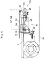
- FIGS. 1 and 2 of the tail lift system 10 are each with the lifting arm 18 and the folding arm 20 on the one hand and the respective swivel arms 140, 143 of the Underride protection 14 interacting swivel actuators 21 provided, by means of which, suitably controlled, the Underride protection 14 from a lowered passive position 22, cf. 4, in a raised passive position 23, see. 5, as well as in an active position 24, cf. FIG. 3, is convertible. As the underrun protection in trailer operation 14 has no effect, it is converted into a upper passive position 23 transferred according to FIG. 5. While the loading operation, the underride guard 14 in a transferred lower passive position 22 as shown in FIG.
- the pivot actuator 21 does not necessarily have to be between Lift arm 18 and / or folding arm 20 and at least that Underride protection 14 can be arranged to act. Is so in an elegant way, at least what the main movement of the underrun protection 14 concerns an automatic Folding movement possible if the stroke actuator or Folding actuator 13, 19 are moved, there are also solutions conceivable where the one articulation point of the respective pivot actuator 21 effectively on the mounting element 17 or even directly rotatable on the vehicle 11 are arranged, whereas the other articulation point of the Swivel actuator 21 on the respective swivel arm 140, 143 is rotatably arranged.
- the swivel actuators 140, 143 are hydraulic here and / or pneumatically operated piston-cylinder devices shown, just like the stroke actuator 13 and the folding actuator 19. But it is also possible that Swivel actuators 21 such as the stroke actuator 13 and the Folding actuator 19 in the form of a motor-driven Spindle system, the motor being hydraulic, can be pneumatically or electrically driven.
Landscapes
- Engineering & Computer Science (AREA)
- Mechanical Engineering (AREA)
- Transportation (AREA)
- Vehicle Step Arrangements And Article Storage (AREA)
Abstract
Description
- Fig. 1
- in perspektivischer Darstellung ein Ladebordwandsystem in Form einer Kompletteinheit, wie sie an einem Fahrzeug befestigt werden kann, unter Weglassung hydraulischer und/oder pneumatischer und/oder elektrischer Mittel,
- Fig. 2
- in perspektivischer Darstellung eine andere Ansicht des in Fig. 1 dargestellten Ladebordwandsystems unter Weglassung der Ladeplattform,
- Fig. 3
- im Teilausschnitt in der Seitenansicht unter Weglassung von für das Verständnis der Erfindung nicht notwendigen Elementen den hinteren Teil eines Fahrzeugs, der mit einem Ladebordwandsystem gemäß der Erfindung versehen ist, bei dem der Unterfahrschutz sich in angehobener Aktivstellung sich befindet,
- Fig. 4
- eine Ansicht gemäß Fig. 3, bei der sich der Unterfahrschutz in abgesenkter Passivstellung befindet und mit abgesenkter Ladeplattform, und
- Fig. 5
- eine Ansicht gemäß den Fig. 3 und 4, bei der sich der Unterfahrschutz in einer angehobenen Passivstellung befindet und bei der die Ladeplattform angehoben ist.
- 10
- Ladebordwandsystem
- 11
- Fahrzeug
- 110
- Ladefläche
- 12
- Ladeplattform
- 13
- Hubaktuator
- 14
- Unterfahrschutz
- 140
- Schwenkarm
- 141
- Ende (Schwenkarm)
- 142
- Ende (Schwenkarm)
- 143
- Schwenkarm
- 144
- Ende (Schwenkarm)
- 145
- Ende (Schwenkarm)
- 146
- Quertraverse
- 147
- Schenkellänge
- 148
- Schenkellänge
- 149
- Winkelelement
- 150
- Winkelelement
- 15
- Schwenkpunkt
- 16
- Schwenkpunkt
- 17
- Montageelement
- 18
- Hubarm
- 19
- Klappaktuator
- 20
- Klapparm
- 21
- Schwenkaktuator
- 22
- abgesenkte Passivstellung
- 23
- angehobene Passivstellung
- 24
- Aktivstellung
- 25
- Anhängerkupplung (oben)
- 26
- Anhängerkupplung (unten)
- 27
- Pfeil
- 28
- Untergrund
Claims (10)
- Ladebordwandsystem (10) zur Anbringung an ein Fahrzeug (11), umfassend wenigstens eine Ladeplattform (12) die mittels eines am Fahrzeug (11) befestigten Hubaktuators (13) zwischen einer oberen und einer unteren Stellung schwenkend hin und her bewegbar ist, sowie einen relativ zum Fahrzeug verschwenkbaren Unterfahrschutz (14), dadurch gekennzeichnet, daß der Unterfahrschutz (14) mit seinem fahrzeugseitigen Schwenkpunkt (15, 16) vom fahrzeugseitigen Schwenkpunkt wenigstens des Hubaktuators (13) und/oder eines Hubarms (18) entkoppelt angeordnet ist.
- Ladebordwandsystem nach Anspruch 1, dadurch gekennzeichnet, daß der Unterfahrschutz (14) mit seinem fahrzeugseitigen Schwenkpunkt (15, 16) vom fahrzeugseitigen Schwenkpunkt wenigstens eines Klappaktuators (19) und/oder eines Klapparms (20) entkoppelt angeordnet ist.
- Ladebordwandsystem nach einem oder beiden der Ansprüche 1 oder 2, dadurch gekennzeichnet, daß der Unterfahrschutz (14) mit seinem Schwenkpunkt (15, 16) direkt oder über ein Montageelement (17) am Fahrzeug (11) befestigt ist.
- Ladebordwandsystem nach Anspruch 3, dadurch gekennzeichnet, daß am Montageelement (17) ebenfalls der Hubaktuator (13) und ein Hubarm (18) und/oder ein Klappaktuator (19) und ein Klapparm (20) angeordnet sind.
- Ladebordwandsystem nach einem oder mehreren der Ansprüche 1 bis 4, dadurch gekennzeichnet, daß der Unterfahrschutz (14) mittels eines Schwenkaktuators (21) aus einer abgesenkten Passivstellung (22) in eine angehobene Passivstellung (23) sowie eine Aktivstellung (24) schwenkbar ist.
- Ladebordwandsystem nach Anspruch 5, dadurch gekennzeichnet, daß der Hubaktuator (21) zwischen Hubarm (18) und/oder am Klapparm (20) und wenigstens dem Unterfahrschutz (14) wirkend angeordnet ist.
- Ladebordwandsystem nach Anspruch 5, dadurch gekennzeichnet, daß der Schwenkaktuator (21) zwischen dem Fahrzeug (11) und dem Montageelement (17) und dem Unterfahrschutz (14) wirkend angeordnet ist.
- Ladebordwandsystem nach einem oder mehrerer der Ansprüche 1 bis 7, dadurch gekennzeichnet, daß der Unterfahrschutz (14) wenigstens zwei Schwenkarme (140, 143) umfaßt, die an ihren einen Enden (141, 144) jeweils ihren Schwenkpunkt (15, 16) aufweisen, und an ihren anderen Enden (142, 145) über eine zu den Schwenkarmen (140, 143) im wesentlichen quer zum Fahrzeug (11) verlaufende Quertraverse (146) verbunden sind.
- Ladebordwandsystem nach Anspruch 8, dadurch gekennzeichnet, daß die Schenkellänge (147, 148) der Schwenkarme (140, 143) derart bemessen ist, daß in oberer angehobener Passivstellung (23) des Unterfahrschutzes (14) eine obere und/oder eine untere, am Fahrzeug (11) angeordnete Anhängerkupplung (25, 26) ungehindert betreibbar ist (Tandemanhängerbetrieb).
- Ladebordwandsystem nach einem oder mehreren der Ansprüche 5 bis 9, dadurch gekennzeichnet, daß der Hubaktuator (13) und/oder der Klappaktuator (19) und/oder der Schwenkaktuator (21) hydraulisch und/oder pneumatisch und/oder elektrisch antreibbar sind.
Priority Applications (1)
| Application Number | Priority Date | Filing Date | Title |
|---|---|---|---|
| EP00120658A EP1190898A1 (de) | 2000-09-21 | 2000-09-21 | Ladebordwandsystem mit Unterfahrschutz |
Applications Claiming Priority (1)
| Application Number | Priority Date | Filing Date | Title |
|---|---|---|---|
| EP00120658A EP1190898A1 (de) | 2000-09-21 | 2000-09-21 | Ladebordwandsystem mit Unterfahrschutz |
Publications (1)
| Publication Number | Publication Date |
|---|---|
| EP1190898A1 true EP1190898A1 (de) | 2002-03-27 |
Family
ID=8169906
Family Applications (1)
| Application Number | Title | Priority Date | Filing Date |
|---|---|---|---|
| EP00120658A Withdrawn EP1190898A1 (de) | 2000-09-21 | 2000-09-21 | Ladebordwandsystem mit Unterfahrschutz |
Country Status (1)
| Country | Link |
|---|---|
| EP (1) | EP1190898A1 (de) |
Cited By (3)
| Publication number | Priority date | Publication date | Assignee | Title |
|---|---|---|---|---|
| FR2851584A1 (fr) * | 2003-02-26 | 2004-08-27 | Secmair | Dispositif d'epandage de cailloux sur une chaussee, pourvu d'une barre anti-encastrement |
| GB2462710A (en) * | 2005-04-06 | 2010-02-24 | Layton Capital Corp F K A Maxo | Lift including rotatable and adjustable under-ride guard |
| CN111376861A (zh) * | 2020-04-14 | 2020-07-07 | 厦门理工学院 | 一种碰撞防护装置 |
Citations (5)
| Publication number | Priority date | Publication date | Assignee | Title |
|---|---|---|---|---|
| DE2426552A1 (de) * | 1974-05-31 | 1975-12-11 | Dautel Emil Kipperbau | Unterfahrschutz fuer mit einer ladevorrichtung versehene lastwagen |
| US4988258A (en) * | 1989-08-11 | 1991-01-29 | Lutz Theodore A | Car catcher |
| US4991890A (en) * | 1988-10-20 | 1991-02-12 | S.B.R. Limited | Retractable bumper bar |
| US5520428A (en) * | 1994-10-27 | 1996-05-28 | Bell; Foyster G. | Movable bumper for vehicles |
| EP0941896A1 (de) | 1998-03-12 | 1999-09-15 | Bär, Gerd | Hubladebühne mit höhenverstellbarem mitfahrenden Unterfahrschutz |
-
2000
- 2000-09-21 EP EP00120658A patent/EP1190898A1/de not_active Withdrawn
Patent Citations (5)
| Publication number | Priority date | Publication date | Assignee | Title |
|---|---|---|---|---|
| DE2426552A1 (de) * | 1974-05-31 | 1975-12-11 | Dautel Emil Kipperbau | Unterfahrschutz fuer mit einer ladevorrichtung versehene lastwagen |
| US4991890A (en) * | 1988-10-20 | 1991-02-12 | S.B.R. Limited | Retractable bumper bar |
| US4988258A (en) * | 1989-08-11 | 1991-01-29 | Lutz Theodore A | Car catcher |
| US5520428A (en) * | 1994-10-27 | 1996-05-28 | Bell; Foyster G. | Movable bumper for vehicles |
| EP0941896A1 (de) | 1998-03-12 | 1999-09-15 | Bär, Gerd | Hubladebühne mit höhenverstellbarem mitfahrenden Unterfahrschutz |
Cited By (4)
| Publication number | Priority date | Publication date | Assignee | Title |
|---|---|---|---|---|
| FR2851584A1 (fr) * | 2003-02-26 | 2004-08-27 | Secmair | Dispositif d'epandage de cailloux sur une chaussee, pourvu d'une barre anti-encastrement |
| GB2462710A (en) * | 2005-04-06 | 2010-02-24 | Layton Capital Corp F K A Maxo | Lift including rotatable and adjustable under-ride guard |
| GB2462710B (en) * | 2005-04-06 | 2010-04-07 | Layton Capital Corp F K A Maxo | Method and apparatus for level ride lift |
| CN111376861A (zh) * | 2020-04-14 | 2020-07-07 | 厦门理工学院 | 一种碰撞防护装置 |
Similar Documents
| Publication | Publication Date | Title |
|---|---|---|
| EP0850147B2 (de) | Anhängerkupplung für kraftfahrzeuge | |
| DE3912194C2 (de) | Fahrzeug | |
| EP2186713B1 (de) | Ballastiervorrichtung und landwirtschaftliches Fahrzeug mit einer solchen Vorrichtung | |
| DE4322985A1 (de) | Flugzeugschlepper ohne Schleppstange | |
| EP1900609A2 (de) | Dolly-achse | |
| DE10157818C1 (de) | Abdeckanordnung für Fahrzeuge mit öffnungsfähigem Fahrzeugdach | |
| DE102007045912A1 (de) | Landwirtschaftliches Fahrzeug | |
| DE2705979C3 (de) | Lastwagen mit in seiner Längsrichtung verschiebbarem Ladebodenabschnitt | |
| EP0569927B1 (de) | Trittbrett für Müllfahrzeuge | |
| DE1036656B (de) | Hydraulische Lenkeinrichtung fuer hintereinander angeordnete Fahrwerke von Strassenfahrzeugen | |
| DE29512152U1 (de) | Anhänger für ein Kraftfahrzeug | |
| DE2063469B2 (de) | Hublader mit verschwenkbarer fahrersitz- und bedienungseinheit | |
| EP1541412A1 (de) | Ladebordwandsystem | |
| DE102010003932A1 (de) | Verdeckvorrichtung für einen Lastentransportbehälter | |
| AT504031B1 (de) | Transportgerät | |
| EP1190898A1 (de) | Ladebordwandsystem mit Unterfahrschutz | |
| DE2119420A1 (de) | Sattelzug | |
| DE102021105025A1 (de) | Schwenkantrieb für Durchladezug | |
| DE3822542A1 (de) | Ladeanhaenger | |
| EP4201192B1 (de) | Ladungssicherungsvorrichtung für landwirtschaftliche transportwagen | |
| DE19820377C1 (de) | Arbeitsfahrzeug mit kippbarer Fahrerplattform und Kippvorrichtung | |
| EP0286576B1 (de) | Transportfahrzeug | |
| DE2246821A1 (de) | Ladevorrichtung fuer lastfahrzeugaufbauten | |
| EP1118500A1 (de) | Ladebordwandsystem | |
| DE3527935A1 (de) | Ladevorrichtung fuer lastfahrzeugaufbauten |
Legal Events
| Date | Code | Title | Description |
|---|---|---|---|
| PUAI | Public reference made under article 153(3) epc to a published international application that has entered the european phase |
Free format text: ORIGINAL CODE: 0009012 |
|
| AK | Designated contracting states |
Kind code of ref document: A1 Designated state(s): AT BE CH CY DE DK ES FI FR GB GR IE IT LI LU MC NL PT SE |
|
| AX | Request for extension of the european patent |
Free format text: AL PAYMENT 20001018;LT PAYMENT 20001018;LV PAYMENT 20001018;MK PAYMENT 20001018;RO PAYMENT 20001018;SI PAYMENT 20001018 |
|
| 17P | Request for examination filed |
Effective date: 20020911 |
|
| AKX | Designation fees paid |
Free format text: AT BE CH CY DE DK ES FI FR GB GR IE IT LI LU MC NL PT SE |
|
| AXX | Extension fees paid |
Free format text: AL PAYMENT 20001018;LT PAYMENT 20001018;LV PAYMENT 20001018;MK PAYMENT 20001018;RO PAYMENT 20001018;SI PAYMENT 20001018 |
|
| 17Q | First examination report despatched |
Effective date: 20040721 |
|
| GRAP | Despatch of communication of intention to grant a patent |
Free format text: ORIGINAL CODE: EPIDOSNIGR1 |
|
| STAA | Information on the status of an ep patent application or granted ep patent |
Free format text: STATUS: THE APPLICATION IS DEEMED TO BE WITHDRAWN |
|
| 18D | Application deemed to be withdrawn |
Effective date: 20060809 |