EP1190497B1 - Verfahren und einrichtung zur interferenzreduzierung zwischen basisstationen in einem breitband cdma-system - Google Patents
Verfahren und einrichtung zur interferenzreduzierung zwischen basisstationen in einem breitband cdma-system Download PDFInfo
- Publication number
- EP1190497B1 EP1190497B1 EP00939622A EP00939622A EP1190497B1 EP 1190497 B1 EP1190497 B1 EP 1190497B1 EP 00939622 A EP00939622 A EP 00939622A EP 00939622 A EP00939622 A EP 00939622A EP 1190497 B1 EP1190497 B1 EP 1190497B1
- Authority
- EP
- European Patent Office
- Prior art keywords
- phase
- synchronization channel
- primary synchronization
- channel
- primary
- Prior art date
- Legal status (The legal status is an assumption and is not a legal conclusion. Google has not performed a legal analysis and makes no representation as to the accuracy of the status listed.)
- Expired - Lifetime
Links
- 238000000034 method Methods 0.000 title claims abstract description 39
- 230000000116 mitigating effect Effects 0.000 title claims abstract description 7
- 230000000694 effects Effects 0.000 claims abstract description 6
- 230000010363 phase shift Effects 0.000 description 30
- 238000010586 diagram Methods 0.000 description 12
- 230000001066 destructive effect Effects 0.000 description 7
- 230000007480 spreading Effects 0.000 description 7
- 238000004891 communication Methods 0.000 description 6
- 125000004122 cyclic group Chemical group 0.000 description 5
- 230000002035 prolonged effect Effects 0.000 description 4
- 238000009825 accumulation Methods 0.000 description 3
- 238000005562 fading Methods 0.000 description 3
- 230000001413 cellular effect Effects 0.000 description 2
- 230000008569 process Effects 0.000 description 2
- 238000001228 spectrum Methods 0.000 description 2
- 101000863856 Homo sapiens Shiftless antiviral inhibitor of ribosomal frameshifting protein Proteins 0.000 description 1
- 230000005540 biological transmission Effects 0.000 description 1
- 230000008859 change Effects 0.000 description 1
- 230000001427 coherent effect Effects 0.000 description 1
- 230000000295 complement effect Effects 0.000 description 1
- 238000010276 construction Methods 0.000 description 1
- 238000001514 detection method Methods 0.000 description 1
- 238000012986 modification Methods 0.000 description 1
- 230000004048 modification Effects 0.000 description 1
- 230000011664 signaling Effects 0.000 description 1
Images


Classifications
-
- H—ELECTRICITY
- H04—ELECTRIC COMMUNICATION TECHNIQUE
- H04J—MULTIPLEX COMMUNICATION
- H04J13/00—Code division multiplex systems
-
- H—ELECTRICITY
- H04—ELECTRIC COMMUNICATION TECHNIQUE
- H04B—TRANSMISSION
- H04B1/00—Details of transmission systems, not covered by a single one of groups H04B3/00 - H04B13/00; Details of transmission systems not characterised by the medium used for transmission
- H04B1/69—Spread spectrum techniques
- H04B1/707—Spread spectrum techniques using direct sequence modulation
- H04B1/7073—Synchronisation aspects
- H04B1/7075—Synchronisation aspects with code phase acquisition
-
- H—ELECTRICITY
- H04—ELECTRIC COMMUNICATION TECHNIQUE
- H04B—TRANSMISSION
- H04B1/00—Details of transmission systems, not covered by a single one of groups H04B3/00 - H04B13/00; Details of transmission systems not characterised by the medium used for transmission
- H04B1/69—Spread spectrum techniques
- H04B1/707—Spread spectrum techniques using direct sequence modulation
- H04B1/7097—Interference-related aspects
-
- H—ELECTRICITY
- H04—ELECTRIC COMMUNICATION TECHNIQUE
- H04B—TRANSMISSION
- H04B2201/00—Indexing scheme relating to details of transmission systems not covered by a single group of H04B3/00 - H04B13/00
- H04B2201/69—Orthogonal indexing scheme relating to spread spectrum techniques in general
- H04B2201/707—Orthogonal indexing scheme relating to spread spectrum techniques in general relating to direct sequence modulation
- H04B2201/70706—Orthogonal indexing scheme relating to spread spectrum techniques in general relating to direct sequence modulation with means for reducing the peak-to-average power ratio
-
- H—ELECTRICITY
- H04—ELECTRIC COMMUNICATION TECHNIQUE
- H04L—TRANSMISSION OF DIGITAL INFORMATION, e.g. TELEGRAPHIC COMMUNICATION
- H04L7/00—Arrangements for synchronising receiver with transmitter
- H04L7/04—Speed or phase control by synchronisation signals
- H04L7/041—Speed or phase control by synchronisation signals using special codes as synchronising signal
-
- H—ELECTRICITY
- H04—ELECTRIC COMMUNICATION TECHNIQUE
- H04W—WIRELESS COMMUNICATION NETWORKS
- H04W56/00—Synchronisation arrangements
- H04W56/0055—Synchronisation arrangements determining timing error of reception due to propagation delay
- H04W56/0065—Synchronisation arrangements determining timing error of reception due to propagation delay using measurement of signal travel time
- H04W56/007—Open loop measurement
- H04W56/0075—Open loop measurement based on arrival time vs. expected arrival time
- H04W56/0085—Open loop measurement based on arrival time vs. expected arrival time detecting a given structure in the signal
Definitions
- the present invention relates to wireless telecommunications systems. More particularly, the present invention relates to a novel and improved method and apparatus for mitigating the effects of destructive interference between the respective synchronization channels broadcast by two or more base stations in a code-division multiple access system.
- TDMA time division multiple access
- FDMA frequency division multiple access
- CDMA code division multiple access
- the CDMA technique has many advantages.
- An exemplary CDMA system is described in U.S. Patent No. 4,901,307, entitled “Spread Spectrum Multiple Access Communication System Using Satellite Or Terrestrial Repeaters", issued February 13, 1990, assigned to the assignee of the present invention.
- An exemplary CDMA system is further described in U.S. Patent No. 5,103,459, entitled “System And Method For Generating Signal Waveforms In A CDMA Cellular Telephone System", issued April 7, 1992, assigned to the assignee of the present invention.
- 3G CDMA communication systems have been proposed including proposals such as cdma2000 and W-CDMA.
- 3G CDMA communication systems are conceptually similar to each other with some significant differences.
- One significant difference is that in the cdma2000 system, each of the base stations operates synchronously.
- each base station in the cdma2000 system operates according to the same universal time reference.
- Each base station transmits a pilot channel having the same PN spreading code, but having a different PN phase offset.
- a mobile station can acquire the pilot channel of one or more base stations by searching through the possible PN phase offsets of the known PN spreading code. Additionally, the mobile station can distinguish among different base stations by their respective PN phase offsets, even though they are using the same PN spreading code.
- each of the base stations operates asynchronously. In other words, there is no universal time reference among separate base stations.
- each base station transmits a "synchronization" channel that comprises two sub-channels.
- the first of the two sub-channels, the primary synchronization channel uses a primary synchronization code, c p , that is common to all base stations.
- the second of the two sub-channels, the secondary synchronization channel uses a cyclic set of secondary synchronization codes, c s , that are not shared by other base stations that are not in the same code group.
- the mobile station in a W-CDMA system can acquire the synchronization channel of one or more base stations by searching for the primary synchronization code, c p of the primary synchronization channel, and then using the timing information derived from the primary synchronization channel to process the secondary synchronization channel.
- FIG. 1 is a timing diagram illustrating the structure of the synchronization channel (SCH) of a W-CDMA system.
- SCH synchronization channel
- the primary synchronization channel is shown as a burst 100 of the primary synchronization code, transmitted at the beginning of each slot.
- the secondary synchronization channel is shown as a burst 102 of one of 17 possible secondary synchronization codes, transmitted in parallel with the primary synchronization code at the beginning of each slot.
- the primary synchronization channel comprises an unmodulated code that is the same for every base station in the system, and is transmitted time-aligned with the slot boundary of the transmitting base station.
- the secondary synchronization channel comprises a sequence of 16 unmodulated code words that are orthogonal to each other and to the primary synchronization code. Each secondary synchronization code word is chosen from a set of 17 different orthogonal codes.
- the sequence on the secondary SCH indicates which of the 32 different code groups the base station PN scrambling code belongs to. 32 sequences are used to encode the 32 different code groups each containing 16 scrambling codes. The 32 sequences are constructed such that their cyclic shifts are unique.
- a non-zero cyclic shift less than 16 of any of the 32 sequences is not equivalent to some cyclic shift of any other of the 32 sequences. This property is used to uniquely determine both the long code group of the base station and the frame timing.
- the term "scrambling" code as used with reference to a W-CDMA system is synonymous with the term “spreading” code as used above with reference to a cdma2000 system.
- the terminology “scrambling” code will be used herein to denote the code used to spread the information signal over the desired bandwidth.
- the mobile station searches for the base station to which it has the lowest path loss. It then determines the downlink scrambling code and frame synchronization of that base station.
- the cell search begins by using the synchronization channel.
- the mobile station uses the primary SCH to acquire slot synchronization to the strongest base station. This may be done with a single matched filter matched to the primary synchronization code, c p , which is common to all base stations.
- the mobile station uses the secondary SCH to find frame synchronization and identify the code group of the base station found in the first step. This is done by correlating the received signal with all possible (16) secondary synchronization codes.
- the mobile station correlates the sequence of 16 code words that are received against the 32 possible sequence patterns and 16 possible cyclic shifts, for a total of 32 x 16 possibilities.
- the mobile station determines the exact PN scrambling code used by the found base station.
- the scrambling code is identified through symbol-by-symbol correlation of the pilot symbols received over one or more common channels with the PN scrambling codes that belong to the code group identified by the second step.
- FIG. 2 A functional block diagram of the multiplexing of the synchronization channel (SCH) with the other downlink physical channels (dedicated channels) is shown in FIG. 2.
- ones generator 202 generates a sequence of logical one values for 256 bits at the beginning of each slot.
- ones generator 202 generates the complex signal 1+j1.
- These ones are complex spread in complex spreader 208 with the primary synchronization code, c p , from primary code generator 206.
- the primary synchronization code is common to all base stations. Together the ones generator 202, primary code generator 206 and complex spreader 208 may be referred to as a "primary synchronization channel generator".
- Ones generator 204 (which may be the same as ones generator 202 ) also generates a sequence of logical one values for 256 chips at the beginning of each slot.
- the ones are complex spread in complex spreader 210 with the secondary synchronization code, c s , from secondary code generator 212.
- the ones generator 204, complex spreader 210, and secondary code generator 212 may be referred to as a "secondary synchronization channel generator”.
- the in-phase (I) and quadrature-phase (Q) components of the primary SCH and the secondary SCH are then respectively combined in combiner 214 to form the synchronization channel (SCH).
- Dedicated channel data is complex spread in complex spreader 218 with a scrambling code, C scramb , which is also unique to the particular base station.
- the scrambled dedicated channel data is combined with the SCH in combiner 216 and forwarded to an I/Q modulator (not shown) for modulation.
- the presently proposed SCH of the W-CDMA system is transmitted with a zero phase offset. Since the base stations in a W-CDMA system operate asynchronously, there will be regions within the coverage area of multiple base stations where the primary SCH from multiple base stations will arrive at the mobile station with the same time alignment. When this happens, detection of the primary SCH timing could become difficult for the mobile station. In the worst case, the primary SCH's from different base stations would arrive at the mobile station so that they destructively interfere with one another, preventing the mobile station from acquiring primary SCH. Furthermore, if the propagation environment is changing slowly, such a state of destructive interference could persist for a considerable length of time. This is of particular concern when the mobile station is stationery, such as in a wireless local loop (WLL) system, or when the mobile station is otherwise moving relatively slowly.
- WLL wireless local loop
- the present invention is a novel and improved method for mitigating the effect of interference between a first base station and a second base station, the first base station and second base stations both sharing a same primary synchronization code.
- the method includes generating a primary synchronization channel having the primary synchronization code.
- all base stations share this primary synchronization code. It is this sharing of a common primary synchronization code that causes code timing collisions.
- the method of the present invention includes rotating the primary synchronization channel in phase according to a phase rotation sequence before transmitting the primary synchronization channel. By rotating the primary synchronization channel in phase according to the phase rotation sequence, instances of prolonged destructive interference may be reduced.
- the phase rotation sequence is pseudorandom in phase, but for simplicity, includes changing phase by integer multiples of ⁇ /2 radians. However, it may include pseudorandomly changing phase by any arbitrary angle. With regard to timing, the phase rotation sequence may include changing phase once per slot, or alternately once per frame. However, it may include changing the phase at any arbitrary periodicity so long as it is changed at a slot boundary (i.e., not during the middle of a slot).
- method also includes generating a secondary synchronization channel having a secondary synchronization code, with the phase rotation sequence being based at least in part on the secondary synchronization code. Basing the phase rotation sequence at least in part on the secondary synchronization code allows for convenience since the secondary synchronization code is already present for other purposes. Additionally, in areas where base stations in different code groups are adjacent to each other, basing the phase rotation sequence at least in part on the secondary synchronization code (which is not shared among base stations in different code groups) will minimize the duration of interference.
- the method includes combining the primary synchronization channel and the secondary synchronization channel to produce a synchronization channel.
- the step of rotating the primary synchronization channel in phase comprises rotating the primary synchronization channel before the combining step.
- the first embodiment rotates only the primary synchronization channel and not the secondary synchronization channel.
- the step of rotating the primary synchronization channel in phase comprises rotating the synchronization channel in phase.
- the second embodiment rotates both the primary and secondary synchronization channels after they have been combined.
- the synchronization channel is combined with a dedicated channel to produce a downlink channel that is then rotated in phase.
- the present invention also includes an apparatus for performing the method summarized above.
- the apparatus includes a primary synchronization channel generator for generating a primary synchronization channel having the primary synchronization code; a phase rotator, coupled to the primary synchronization channel generator, for rotating the primary synchronization channel in phase according to a phase rotation sequence; and a transmitter, coupled to the phase rotator, for transmitting the primary synchronization channel.
- the apparatus further comprises a first combiner for combining the primary synchronization channel and the secondary synchronization channel to produce a synchronization channel; wherein the phase rotator is coupled between an output of the primary synchronization channel generator and an input of the first combiner.
- the phase rotator is coupled to an output of the first combiner.
- a second combiner combines the synchronization channel and a dedicated channel to produce a downlink channel, and the phase rotator is coupled to an output of the second combiner.
- FIGS. 1 and 2 The present invention will now be described in detail with reference to the exemplary W-CDMA system illustrated by FIGS. 1 and 2. It will be understood by one of ordinary skill in the art that the present invention is equally applicable to other communication systems in which fading is caused by destructive interference arising from the same synchronization or pilot channel being transmitted by more than one base station in the same geographic region.
- FIG. 3 a functional block diagram of a first embodiment of the present invention is illustrated.
- FIG. 3 is similar to FIG. 2, with the addition of phase rotator 302 between complex spreader 208 and combiner 214.
- Phase rotator 302 introduces a phase rotation of the primary SCH, after spreading with the primary synchronization code, c p , and before combination with the secondary SCH.
- the signals illustrated in FIG. 3 as traveling between functional blocks are, in general, complex I and Q signals.
- the phase shift introduced by phase rotator 302 is pseudorandomly chosen for each slot from among a set of predefined phase shifts.
- a suggested set of predefined phase shifts would include zero, ⁇ /2, ⁇ , and 3 ⁇ /2 radians.
- Other predefined sets may be used in various embodiments.
- the present invention is not limited by the amount of the phase shift(s) chosen.
- phase rotator 302 generates the pseudorandom phase shift sequence, as well as introducing that phase shift into the primary SCH.
- the pseudorandom phase shift sequence may be provided to phase rotator 302 by a separate functional element.
- one convenient source of a pseudorandom number for controlling the phase shift introduced by phase rotator 302 is the secondary synchronization code, c s , generated by secondary, code generator 212.
- the secondary synchronization code is not common to all base stations, but only to those of the same code group, it may be advantageously used to ensure that two base stations of different code groups having a phase collision of the primary SCH will not introduce the same pseudorandom sequence of phase shifts into their primary SCH, thereby prolonging the duration of the mutual interference.
- the secondary SCH is a binary data stream of logical ones and zeros, if the first chip were a "one” it could cause phase rotator 302 to introduce a phase shift of ⁇ radians into the primary SCH, whereas a "zero" could cause phase rotator 302 to introduce no phase shift into the primary SCH.
- the secondary SCH could be taken two chips at a time, with the '00' sequence corresponding to a zero phase shift, the '01' sequence corresponding to a phase shift of ⁇ /2 radians, the '10' sequence corresponding to a phase shift of ⁇ radians, and the '11' sequence corresponding to a phase shift of 3 ⁇ /2 radians.
- many different implementation schemes or pseudorandom sequences may be used, whether or not they are related to the secondary synchronization code.
- Phase rotator 302 preferably changes the phase of the primary SCH only once per burst transmission, which equates to once per slot.
- each repetition of the primary SCH would have a pseudorandom phase shift.
- the first slot of a frame might transmit the primary SCH with a phase shift of ⁇ radians
- the second slot of the same frame might transmit the primary SCH with a phase shift of zero radians.
- phase rotator 302 may change the phase of the primary SCH once per frame, rather than once per slot.
- each repetition of the primary SCH during a first frame would have a first pseudorandom phase shift
- each repetition of the primary SCH during a second frame would have a second pseudorandom phase shift, where the first and second pseudorandom phase shifts are not necessarily equal.
- many different timing schemes for pseudorandomly changing the phase of the primary SCH may be used, whether or not they are based on a slot or frame periodicity.
- phase rotator 302 of FIG. 3 introduces a pseudorandom phase shift in the primary SCH, after spreading by the primary synchronization code, and before combination with the secondary SCH.
- This pseudorandom phase shift mitigates the problem of phase collisions between multiple base stations, operating asynchronously, which all share the same primary synchronization code.
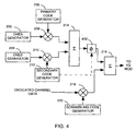
- FIG. 4 differs from FIG. 3 in that the phase rotation introduced by phase rotator 402 of FIG. 4 occurs after the combination of the primary SCH and the secondary SCH by combiner 214, rather than before their combination.
- rotator 402 may be similar in construction and functionality to phase rotator 302 of FIG. 3.
- the amount of phase rotation and the timing of the phase rotation performed by either phase rotator 302 or phase rotator 402 may be unknown, a priori, to the mobile station.
- the mobile station will still be able to acquire and demodulate the primary and secondary SCH by using conventional receivers that are well known in the art.
- the phase variations introduced by phase rotators 302 or 402 appear merely as variations in the propagation environment.
- the use of virtually any phase rotation sequence by phase rotator 302 or phase rotator 402 will suffice for these embodiments.
- phase rotator 502 introduces phase variations into the combined downlink (base station to mobile station) channel.
- phase rotator 502 is similar in operation and functionality to phase rotator 302 and phase rotator 402.
- the synchronization channel and the dedicated data channel are combined in combiner 216 prior to the introduction of phase rotation by phase rotator 502.
- the pilot symbols that are transmitted at the beginning of every slot of the dedicated data channel will be rotated in phase from slot to slot or frame to frame.
- a typical coherent demodulator (not shown) in the mobile station will generally accumulate pilot phase and energy over several consecutive slots in order to generate a stable channel estimate for coherently demodulating the data.
- abrupt and pseudorandom phase variations in the pilot symbols introduced by phase rotator 502 will lead to difficulty in pilot phase accumulation by the mobile station unless the mobile station knows, a priori, the pseudorandom phase rotation sequence or pattern. This would, in turn, lead to less reliable data demodulation and errors.
- the pseudorandom phase shift sequence introduced by phase rotator 502 may be based, as described above with reference to FIG. 3, on the secondary synchronization code, c s , contained in secondary code generator 212.
- the secondary synchronization code, C s is provided in the W-CDMA standard and is used by the mobile station in the second stage of the acquisition process. It is well known to the mobile station once it has demodulated the secondary SCH, and before it begins to demodulate the dedicated channels.
- the embodiment of FIG. 5 may be advantageously used to avoid the difficulties associated with pilot phase accumulation by the mobile station.
- the mobile station apply a phase rotation the received signal that is opposite of the one introduced by phase rotator 502 according to the secondary synchronization code before accumulation of the pilot phase.
- any method suggested above of encoding phase variations from the secondary synchronization code may be used (i.e., '0' is zero rotation, '1' is a rotation of ⁇ ), and any timing method suggested above may be used (i.e., once per slot, once per frame, etc.).
- the base station may provide the particular pseudorandom phase shift sequence that it is currently using in an overhead signaling message to the mobile station.
- the pseudorandom phase shift sequence may be explicitly specified in the standard.
- the pseudorandom phase shift may be derived from any unique or semi-unique identifier of the base station.
- FIG. 6 illustrates a flow diagram of the method of the present invention.
- the method described in FIG. 6 generically may be performed by any of the embodiments of FIGS. 3, 4, or 5.
- the primary synchronization channel is generated. This may be performed, for example, by spreading the output of ones generator 202 with the primary synchronization code signal generated by primary code generator 206 in complex spreader 208.
- the phase of the primary synchronization channel is rotated according to a phase rotation sequence. This step may be performed, for example, by any of phase rotator 302, phase rotator 402, or phase rotator 502. It should be noted that in the embodiment of FIG. 3, the phase rotator 302 acts on the primary SCH alone, whereas in the embodiments of FIGS.
- the phase rotators 402 and 502 respectively operate on a combination signal which inherently includes the primary SCH.
- the phase rotation sequence may be any recurring sequence sufficient to prevent prolonged fading due to destructive interference.
- the phase rotation sequence may be pseudorandomly shifting between zero and ⁇ radians every slot.
- Other example phase rotation sequences are given above.
- the primary synchronization channel is transmitted. This step may be performed by any conventional transmitter (not shown) within a base station that uses the present invention.
- a base station in a W-CDMA system will be able to avoid prolonged "fading" of the downlink signal caused by timing collisions on the primary SCH.
- the phase of the primary SCH By changing the phase of the primary SCH, the destructive interference that would otherwise occur in some regions in the mutual geographic coverage area of two base stations will be mitigated.
- the method of the present invention as implemented by the various embodiments described herein, will enable a mobile station to more rapidly acquire the downlink of the base station in such mutual interference situations.
Landscapes
- Engineering & Computer Science (AREA)
- Computer Networks & Wireless Communication (AREA)
- Signal Processing (AREA)
- Mobile Radio Communication Systems (AREA)
- Radio Transmission System (AREA)
Claims (20)
- Verfahren zur Reduzierung des Effekts der Interferenz zwischen einer ersten Basisstation und einer zweiten Basisstation, wobei die erste Basisstation und die zweite Basisstation beide einen Primärsynchronisationscode teilen, wobei das Verfahren folgende Schritte vorsieht:Erzeugen eines primären Synchronisationskanals mit dem erwähnten primären Synchronisationscode;Drehen (Rotation) des primären Synchronisationskanals in Phase gemäß einer Phasenrotationssequenz; undÜbertragen oder Senden des erwähnten primären Synchronisationskanals.
- Verfahren nach Anspruch 1, wobei die Phasendreh- bzw. Rotationssequenz pseudozufällig ist.
- Verfahren nach Anspruch 2, wobei die Phasendrehsequenz das Ändern der Phase einmal pro Schlitz umfasst.
- Verfahren nach Anspruch 2, wobei die Phasendrehsequenz die Änderung der Phase einmal pro Rahmen umfasst.
- Verfahren nach Anspruch 3, wobei die Phasendrehsequenz das Ändern der Phase um ganzzahlige Vielfache von π/2 Radian umfasst.
- Verfahren nach Anspruch 4, wobei die Phasendrehsequenz das Ändern der Phase um ganzzahlige Vielfache von π/2 Radian umfasst.
- Verfahren nach Anspruch 2, wobei der Schritt des Erzeugens eines sekundären Synchronisationskanals mit einem sekundären Synchronisationscode vorgesehen ist, wobei die Phasendrehsequenz mindestens teilweise auf dem sekundären Synchronisationscode basiert.
- Verfahren nach Anspruch 7, wobei ferner der folgende Schritt vorgesehen ist:wobei der Schritt der Drehung des primären Synchronisationskanals in Phase das Drehen des primären Synchronisationskanals vor dem erwähnten Kombinierschritt aufweist.Kombinieren des Primärsynchronisationskanals mit dem sekundären Synchronisationskanal um einen Synchronisationskanal zu erzeugen;
- Verfahren nach Anspruch 7, wobei ferner der folgende Schritt vorgesehen ist:wobei der Schritt des Drehens des primären Synchronisationskanals in Phase das Drehen des erwähnten Synchronisationskanals in Phase umfasst.Kombinieren des primären Synchronisationskanals und des sekundären Synchronisationskanals zur Erzeugung eines Synchronisationskanals;
- Verfahren nach Anspruch 7, wobei ferner die folgenden Schritte vorgesehen sind:wobei der Schritt des Drehens des primären Synchronisationskanals in Phase das Drehen des Herabverbindungskanals in Phase umfasst.Erzeugen eines zugewiesenen oder gewidmeten (dedizierten) Kanals;Kombinieren des erwähnten primären Synchronisationskanals mit dem erwähnten sekundären Synchronisationskanals zur Erzeugung eines Synchronisationskanals; undKombinieren des Synchronisationskanals und des gewidmeten Kanals zur Erzeugung eines Herabverbindungskanals;
- Vorrichtung zum Vermindern bzw. Reduzieren des Interferenzeffekts zwischen einer ersten Basisstation und einer zweiten Basisstation, wobei die erste Basisstation und die zweite Basisstation beide einen gemeinsamen primären Synchronisationscode teilen, wobei die Vorrichtung Folgendes aufweist:einen primären Synchronisationskanalgenerator zur Erzeugung eines primären Synchronisationskanals mit dem erwähnten primären Synchronisationscode;einen Phasendreher oder Phasenrotierer, gekuppelt mit dem primären Synchronisationskanalgenerator zum Drehen oder Rotieren des primären Synchronisationskanals in Phase gemäß einer Phasendreh- oder Rotationssequenz; undeinen Sender, gekoppelt mit dem Phasendreher zur Sendung oder Übertragung des erwähnten primären Synchronisationskanals.
- Vorrichtung nach Anspruch 11, wobei die Phasendrehsequenz pseudozufällig ist.
- Vorrichtung nach Anspruch 12, wobei die Phasendrehsequenz das Ändern der Phase ein Mal pro Schlitz aufweist.
- Vorrichtung nach Anspruch 12, wobei die Phasendrehsequenz das Ändern der Phase ein Mal pro Rahmen aufweist.
- Vorrichtung nach Anspruch 13; wobei die Phasendrehsequenz die Phasenänderung durch ganzzahlige Vielfache von π/2 Radian aufweist.
- Vorrichtung nach Anspruch 14, wobei die Phasendrehsequenz das Ändern der Phase um ganzzahlige Vielfache von π/2 Radian aufweist.
- Vorrichtung nach Anspruch 12, wobei ferner ein Sekundärsynchronisationskanalgenerator vorgesehen ist, und zwar zum Erzeugen eines sekundären Synchronisationskanals mit einem sekundären Synchronisationskode, wobei die Phasendrehsequenz mindestens teilweise auf dem erwähnten sekundären Synchronisationscode basiert.
- Vorrichtung nach Anspruch 17, wobei ferner Folgendes vorgesehen ist:wobei der Phasendreher zwischen einen Ausgang des Primärsynchronisationskanatgenerators und einen Eingang des ersten Kombinierers gekoppelt ist.Ein erster Kombinierer zum Kombinieren des primären Synchronisationskanals und des sekundären Synchronisationskanals zur Erzeugung eines Synchronisationskanals;
- Vorrichtung nach Anspruch 17, wobei ferner Folgendes vorgesehen ist:wobei der Phasendreher mit einem Ausgang des ersten Kombinierers gekoppelt ist.Ein erster Kombinierer zum Kombinieren des primären Synchronisationskanals und des sekundären Synchronisationskanals zur Erzeugung eines Synchronisationskanals;
- Vorrichtung nach Anspruch 17, wobei ferner Folgendes vorgesehen ist:wobei der erwähnte Phasendreher mit einem Ausgang des zweiten Kombinierers gekoppelt ist.Ein erster Kombinierer zum Kombinieren des erwähnten primären Synchronisationskanals und des erwähnten sekundären Synchronisationskanals zur Erzeugung eines Synchronisationskanals; undein zweiter Kombinierer zum Kombinieren des erwähnten Synchronisationskanals und eines gewidmeten Kanals zur Erzeugung eines Herabverbindungskanals;
Applications Claiming Priority (3)
| Application Number | Priority Date | Filing Date | Title |
|---|---|---|---|
| US09/328,119 US6385264B1 (en) | 1999-06-08 | 1999-06-08 | Method and apparatus for mitigating interference between base stations in a wideband CDMA system |
| US328119 | 1999-06-08 | ||
| PCT/US2000/015619 WO2000076080A1 (en) | 1999-06-08 | 2000-06-07 | Method and apparatus for mitigating interference between base stations in a wideband cdma system |
Publications (2)
| Publication Number | Publication Date |
|---|---|
| EP1190497A1 EP1190497A1 (de) | 2002-03-27 |
| EP1190497B1 true EP1190497B1 (de) | 2005-10-26 |
Family
ID=23279608
Family Applications (1)
| Application Number | Title | Priority Date | Filing Date |
|---|---|---|---|
| EP00939622A Expired - Lifetime EP1190497B1 (de) | 1999-06-08 | 2000-06-07 | Verfahren und einrichtung zur interferenzreduzierung zwischen basisstationen in einem breitband cdma-system |
Country Status (11)
| Country | Link |
|---|---|
| US (1) | US6385264B1 (de) |
| EP (1) | EP1190497B1 (de) |
| JP (1) | JP2003501936A (de) |
| KR (1) | KR100748402B1 (de) |
| CN (1) | CN1152480C (de) |
| AT (1) | ATE308164T1 (de) |
| AU (1) | AU5468200A (de) |
| BR (1) | BR0011414A (de) |
| DE (1) | DE60023497T2 (de) |
| HK (1) | HK1044243A1 (de) |
| WO (1) | WO2000076080A1 (de) |
Cited By (1)
| Publication number | Priority date | Publication date | Assignee | Title |
|---|---|---|---|---|
| JP2003501936A (ja) * | 1999-06-08 | 2003-01-14 | クゥアルコム・インコーポレイテッド | 広帯域cdmaシステムにおいて基地局間の干渉を緩和するための方法及び装置 |
Families Citing this family (82)
| Publication number | Priority date | Publication date | Assignee | Title |
|---|---|---|---|---|
| US6665277B1 (en) * | 1998-10-16 | 2003-12-16 | Texas Instruments Incorporated | Comma free codes for fast cell search using tertiary synchronization channel |
| US7952511B1 (en) | 1999-04-07 | 2011-05-31 | Geer James L | Method and apparatus for the detection of objects using electromagnetic wave attenuation patterns |
| US6717930B1 (en) * | 2000-05-22 | 2004-04-06 | Interdigital Technology Corporation | Cell search procedure for time division duplex communication systems using code division multiple access |
| US7103085B1 (en) * | 1999-06-18 | 2006-09-05 | Texas Instruments Incorporated | Wireless communications system with secondary synchronization code based on values in primary synchronization code |
| KR100434262B1 (ko) * | 1999-08-17 | 2004-06-04 | 엘지전자 주식회사 | 순방향 다중 스크램블링 코드 발생 방법 |
| KR100429545B1 (ko) * | 1999-08-17 | 2004-04-28 | 삼성전자주식회사 | 이동통신 시스템의 스크램블링 부호의 식별자 통신방법 |
| US6834046B1 (en) * | 1999-10-05 | 2004-12-21 | Texas Instruments Incorporated | Acquisition of an unevenly spaced synchronization channel in a wireless communication system |
| US6631125B1 (en) * | 1999-10-20 | 2003-10-07 | Nokia Corporation | Channel set-up in wideband, code division multiple access systems |
| US6665288B1 (en) * | 1999-11-08 | 2003-12-16 | Ericsson Inc. | Method and apparatus for reducing synchronization code interference in CDMA communications systems |
| DE10001854A1 (de) * | 2000-01-18 | 2001-08-02 | Infineon Technologies Ag | Verfahren und Vorrichtung zur Ermittlung der Trägerfrequenz von Basisstationen im mobilen Empfänger eines mit W-CDMA arbeitenden zellularen Mobilfunksystems |
| ES2269908T3 (es) * | 2000-05-10 | 2007-04-01 | Mitsubishi Electric Information Technology Centre Europe B.V. | Metodo para adjudicar codigos de sincronizacion secundarios a una estacion base de un sistema de telecomunicaciones moviles. |
| US8576754B2 (en) | 2000-05-22 | 2013-11-05 | Interdigital Technology Corporation | TDD base station for code group synchronization |
| US8363744B2 (en) | 2001-06-10 | 2013-01-29 | Aloft Media, Llc | Method and system for robust, secure, and high-efficiency voice and packet transmission over ad-hoc, mesh, and MIMO communication networks |
| JPWO2002032029A1 (ja) * | 2000-10-06 | 2004-02-26 | 株式会社鷹山 | 受信装置 |
| JP4368514B2 (ja) * | 2000-10-30 | 2009-11-18 | 三菱電機株式会社 | セルサーチ制御装置およびセルサーチ制御方法 |
| US6728203B2 (en) * | 2001-05-18 | 2004-04-27 | Telefonaktiebolaget L.M. Ericsson | Systems and methods for selecting a cell in a communications network |
| US7158559B2 (en) | 2002-01-15 | 2007-01-02 | Tensor Comm, Inc. | Serial cancellation receiver design for a coded signal processing engine |
| US8085889B1 (en) | 2005-04-11 | 2011-12-27 | Rambus Inc. | Methods for managing alignment and latency in interference cancellation |
| US6754190B2 (en) | 2001-10-17 | 2004-06-22 | Motorola, Inc. | Channel selection method used in a communication system |
| JP4125676B2 (ja) * | 2001-10-17 | 2008-07-30 | モトローラ・インコーポレイテッド | マルチユーザ・システムでデータ通信を行うための方法とデバイス |
| US7260506B2 (en) * | 2001-11-19 | 2007-08-21 | Tensorcomm, Inc. | Orthogonalization and directional filtering |
| US20050101277A1 (en) * | 2001-11-19 | 2005-05-12 | Narayan Anand P. | Gain control for interference cancellation |
| US7693123B2 (en) * | 2001-11-29 | 2010-04-06 | Interdigital Technology Corporation | System and method using primary and secondary synchronization codes during cell search |
| US7065064B2 (en) * | 2001-12-20 | 2006-06-20 | Interdigital Technology Corporation | Cell search using peak quality factors |
| US6907028B2 (en) * | 2002-02-14 | 2005-06-14 | Nokia Corporation | Clock-based time slicing |
| US7292552B2 (en) | 2002-03-14 | 2007-11-06 | Qualcomm Incorporated | Method and apparatus for reducing interference in a wireless communication system |
| US7095709B2 (en) * | 2002-06-24 | 2006-08-22 | Qualcomm, Incorporated | Diversity transmission modes for MIMO OFDM communication systems |
| US20040208238A1 (en) * | 2002-06-25 | 2004-10-21 | Thomas John K. | Systems and methods for location estimation in spread spectrum communication systems |
| TWI324023B (en) * | 2002-07-31 | 2010-04-21 | Interdigital Tech Corp | Start-up automatic frequency control (afc) method and apparatus |
| US8194770B2 (en) | 2002-08-27 | 2012-06-05 | Qualcomm Incorporated | Coded MIMO systems with selective channel inversion applied per eigenmode |
| US7058034B2 (en) * | 2002-09-09 | 2006-06-06 | Nokia Corporation | Phase shifted time slice transmission to improve handover |
| US7577186B2 (en) * | 2002-09-20 | 2009-08-18 | Tensorcomm, Inc | Interference matrix construction |
| US7876810B2 (en) | 2005-04-07 | 2011-01-25 | Rambus Inc. | Soft weighted interference cancellation for CDMA systems |
| US8761321B2 (en) * | 2005-04-07 | 2014-06-24 | Iii Holdings 1, Llc | Optimal feedback weighting for soft-decision cancellers |
| US20050180364A1 (en) * | 2002-09-20 | 2005-08-18 | Vijay Nagarajan | Construction of projection operators for interference cancellation |
| US7787572B2 (en) | 2005-04-07 | 2010-08-31 | Rambus Inc. | Advanced signal processors for interference cancellation in baseband receivers |
| US7808937B2 (en) | 2005-04-07 | 2010-10-05 | Rambus, Inc. | Variable interference cancellation technology for CDMA systems |
| US7463609B2 (en) * | 2005-07-29 | 2008-12-09 | Tensorcomm, Inc | Interference cancellation within wireless transceivers |
| US8005128B1 (en) | 2003-09-23 | 2011-08-23 | Rambus Inc. | Methods for estimation and interference cancellation for signal processing |
| US20050123080A1 (en) * | 2002-11-15 | 2005-06-09 | Narayan Anand P. | Systems and methods for serial cancellation |
| US8179946B2 (en) * | 2003-09-23 | 2012-05-15 | Rambus Inc. | Systems and methods for control of advanced receivers |
| US20040127207A1 (en) * | 2002-09-25 | 2004-07-01 | Interdigital Technology Corporation | Programmable radio interface |
| WO2004036811A2 (en) * | 2002-10-15 | 2004-04-29 | Tensorcomm Inc. | Method and apparatus for interference suppression with efficient matrix inversion in a ds-cdma system |
| US8169944B2 (en) | 2002-10-25 | 2012-05-01 | Qualcomm Incorporated | Random access for wireless multiple-access communication systems |
| US8320301B2 (en) | 2002-10-25 | 2012-11-27 | Qualcomm Incorporated | MIMO WLAN system |
| US8570988B2 (en) | 2002-10-25 | 2013-10-29 | Qualcomm Incorporated | Channel calibration for a time division duplexed communication system |
| US20040081131A1 (en) | 2002-10-25 | 2004-04-29 | Walton Jay Rod | OFDM communication system with multiple OFDM symbol sizes |
| US8218609B2 (en) | 2002-10-25 | 2012-07-10 | Qualcomm Incorporated | Closed-loop rate control for a multi-channel communication system |
| US8208364B2 (en) * | 2002-10-25 | 2012-06-26 | Qualcomm Incorporated | MIMO system with multiple spatial multiplexing modes |
| US7324429B2 (en) | 2002-10-25 | 2008-01-29 | Qualcomm, Incorporated | Multi-mode terminal in a wireless MIMO system |
| US8134976B2 (en) | 2002-10-25 | 2012-03-13 | Qualcomm Incorporated | Channel calibration for a time division duplexed communication system |
| US7002900B2 (en) | 2002-10-25 | 2006-02-21 | Qualcomm Incorporated | Transmit diversity processing for a multi-antenna communication system |
| US7986742B2 (en) * | 2002-10-25 | 2011-07-26 | Qualcomm Incorporated | Pilots for MIMO communication system |
| US8170513B2 (en) | 2002-10-25 | 2012-05-01 | Qualcomm Incorporated | Data detection and demodulation for wireless communication systems |
| WO2004042948A1 (en) * | 2002-10-31 | 2004-05-21 | Tensorcomm, Incorporated | Systems and methods for reducing interference in cdma systems |
| WO2004073159A2 (en) * | 2002-11-15 | 2004-08-26 | Tensorcomm, Incorporated | Systems and methods for parallel signal cancellation |
| UA90244C2 (ru) * | 2003-01-07 | 2010-04-26 | Квелкомм Инкорпорейтед | Схема передачи пилот-сигналов для систем радиосвязи с передачей на несколько несущих |
| US7280467B2 (en) * | 2003-01-07 | 2007-10-09 | Qualcomm Incorporated | Pilot transmission schemes for wireless multi-carrier communication systems |
| US7218641B2 (en) * | 2003-03-11 | 2007-05-15 | Motorola, Inc. | Method and apparatus for adaptive processing gain for multiple source devices in a communications system |
| US7023817B2 (en) * | 2003-03-11 | 2006-04-04 | Motorola, Inc. | Method and apparatus for source device synchronization in a communication system |
| US9473269B2 (en) | 2003-12-01 | 2016-10-18 | Qualcomm Incorporated | Method and apparatus for providing an efficient control channel structure in a wireless communication system |
| US20050169354A1 (en) * | 2004-01-23 | 2005-08-04 | Olson Eric S. | Systems and methods for searching interference canceled data |
| US7477710B2 (en) * | 2004-01-23 | 2009-01-13 | Tensorcomm, Inc | Systems and methods for analog to digital conversion with a signal cancellation system of a receiver |
| US7660583B2 (en) * | 2004-03-19 | 2010-02-09 | Nokia Corporation | Advanced handover in phased-shifted and time-sliced networks |
| CN1691555B (zh) * | 2004-04-30 | 2010-04-14 | 诺基亚西门子通信系统技术(北京)有限公司 | Td-scdma系统中减少上行同步信道干扰的方法 |
| US20060125689A1 (en) * | 2004-12-10 | 2006-06-15 | Narayan Anand P | Interference cancellation in a receive diversity system |
| US20060229051A1 (en) * | 2005-04-07 | 2006-10-12 | Narayan Anand P | Interference selection and cancellation for CDMA communications |
| US7826516B2 (en) | 2005-11-15 | 2010-11-02 | Rambus Inc. | Iterative interference canceller for wireless multiple-access systems with multiple receive antennas |
| US7466749B2 (en) | 2005-05-12 | 2008-12-16 | Qualcomm Incorporated | Rate selection with margin sharing |
| US8358714B2 (en) | 2005-06-16 | 2013-01-22 | Qualcomm Incorporated | Coding and modulation for multiple data streams in a communication system |
| KR100872043B1 (ko) * | 2005-12-29 | 2008-12-05 | 삼성전자주식회사 | 광대역 무선접속 통신시스템에서 파일럿 패턴 결정 장치 및방법 |
| US7706249B2 (en) * | 2006-02-08 | 2010-04-27 | Motorola, Inc. | Method and apparatus for a synchronization channel in an OFDMA system |
| US7983143B2 (en) | 2006-02-08 | 2011-07-19 | Motorola Mobility, Inc. | Method and apparatus for initial acquisition and cell search for an OFDMA system |
| US7911935B2 (en) * | 2006-02-08 | 2011-03-22 | Motorola Mobility, Inc. | Method and apparatus for interleaving sequence elements of an OFDMA synchronization channel |
| JP2007251862A (ja) * | 2006-03-20 | 2007-09-27 | Hitachi Kokusai Electric Inc | デジタル伝送の方向調整方法 |
| CN101490978A (zh) * | 2006-04-20 | 2009-07-22 | 德克萨斯仪器股份有限公司 | 下行链路同步化信道和蜂窝系统的方法 |
| US8031745B2 (en) * | 2006-04-20 | 2011-10-04 | Texas Instruments Incorporated | Downlink synchronization channel and methods for cellular systems |
| CN106304318B (zh) * | 2006-04-20 | 2020-02-11 | 苹果公司 | 下行链路同步化信道和蜂窝系统的方法 |
| US8223625B2 (en) * | 2006-08-23 | 2012-07-17 | Qualcomm, Incorporated | Acquisition in frequency division multiple access systems |
| CA2665218C (en) * | 2006-10-03 | 2013-07-16 | Qualcomm Incorporated | Method and apparatus for processing primary and secondary synchronization signals for wireless communication |
| EP2360957A1 (de) * | 2010-02-11 | 2011-08-24 | Alcatel Lucent | Verfahren und System zur Reduzierung der Interferenzen in einem zellularen Funkkommunikationssystem mit dem Wiederverwendungsfaktor 1 |
| US9578469B2 (en) | 2014-10-02 | 2017-02-21 | Motorola Solutions, Inc. | Method and system for direct mode communication within a talkgroup |
Family Cites Families (6)
| Publication number | Priority date | Publication date | Assignee | Title |
|---|---|---|---|---|
| US4901307A (en) | 1986-10-17 | 1990-02-13 | Qualcomm, Inc. | Spread spectrum multiple access communication system using satellite or terrestrial repeaters |
| US5103459B1 (en) | 1990-06-25 | 1999-07-06 | Qualcomm Inc | System and method for generating signal waveforms in a cdma cellular telephone system |
| US5930366A (en) * | 1997-08-29 | 1999-07-27 | Telefonaktiebolaget L M Ericsson | Synchronization to a base station and code acquisition within a spread spectrum communication system |
| US6026117A (en) * | 1997-10-23 | 2000-02-15 | Interdigital Technology Corporation | Method and apparatus for generating complex four-phase sequences for a CDMA communication system |
| US6385264B1 (en) * | 1999-06-08 | 2002-05-07 | Qualcomm Incorporated | Method and apparatus for mitigating interference between base stations in a wideband CDMA system |
| JP4389346B2 (ja) * | 2000-04-27 | 2009-12-24 | ソニー株式会社 | 同期検出装置及び方法、並びに無線信号受信装置及び方法 |
-
1999
- 1999-06-08 US US09/328,119 patent/US6385264B1/en not_active Expired - Lifetime
-
2000
- 2000-06-07 AU AU54682/00A patent/AU5468200A/en not_active Abandoned
- 2000-06-07 CN CNB008086893A patent/CN1152480C/zh not_active Expired - Fee Related
- 2000-06-07 JP JP2001502242A patent/JP2003501936A/ja active Pending
- 2000-06-07 KR KR1020017015829A patent/KR100748402B1/ko not_active IP Right Cessation
- 2000-06-07 WO PCT/US2000/015619 patent/WO2000076080A1/en active Search and Examination
- 2000-06-07 EP EP00939622A patent/EP1190497B1/de not_active Expired - Lifetime
- 2000-06-07 BR BR0011414-6A patent/BR0011414A/pt not_active IP Right Cessation
- 2000-06-07 AT AT00939622T patent/ATE308164T1/de not_active IP Right Cessation
- 2000-06-07 DE DE60023497T patent/DE60023497T2/de not_active Expired - Lifetime
-
2002
- 2002-08-09 HK HK02105835A patent/HK1044243A1/xx not_active IP Right Cessation
Cited By (1)
| Publication number | Priority date | Publication date | Assignee | Title |
|---|---|---|---|---|
| JP2003501936A (ja) * | 1999-06-08 | 2003-01-14 | クゥアルコム・インコーポレイテッド | 広帯域cdmaシステムにおいて基地局間の干渉を緩和するための方法及び装置 |
Also Published As
| Publication number | Publication date |
|---|---|
| BR0011414A (pt) | 2002-04-23 |
| KR20020009630A (ko) | 2002-02-01 |
| CN1152480C (zh) | 2004-06-02 |
| US6385264B1 (en) | 2002-05-07 |
| JP2003501936A (ja) | 2003-01-14 |
| AU5468200A (en) | 2000-12-28 |
| ATE308164T1 (de) | 2005-11-15 |
| DE60023497T2 (de) | 2006-08-03 |
| CN1354917A (zh) | 2002-06-19 |
| WO2000076080A1 (en) | 2000-12-14 |
| KR100748402B1 (ko) | 2007-08-10 |
| EP1190497A1 (de) | 2002-03-27 |
| DE60023497D1 (de) | 2005-12-01 |
| HK1044243A1 (en) | 2002-10-11 |
Similar Documents
| Publication | Publication Date | Title |
|---|---|---|
| EP1190497B1 (de) | Verfahren und einrichtung zur interferenzreduzierung zwischen basisstationen in einem breitband cdma-system | |
| US5917852A (en) | Data scrambling system and method and communications system incorporating same | |
| KR100254249B1 (ko) | 동위상 및 직교위상 스펙트럼 확산 통신채널을 통해 신호전송을 분할하기 위한 방법 및 장치 | |
| JP3559738B2 (ja) | コンプレクス・スクランブリング・コード・シーケンスを発生するための方法及び装置 | |
| US7468943B2 (en) | Transmission/Reception apparatus and method in a mobile communication system | |
| Yang et al. | Chaotic digital code-division multiple access (CDMA) communication systems | |
| US7505440B2 (en) | Method and apparatus for orthogonally overlaying variable chip rate spread spectrum signals | |
| KR100711564B1 (ko) | 코드 분할 다중 접속 방식을 이용한 시분할 쌍방향 통신시스템의 셀 검색 절차 | |
| KR20000076941A (ko) | 코드 분할 다중 접속(cdma)을 이용한 전기통신시스템의 향상 | |
| US20030128787A1 (en) | Method and apparatus for mitigating interference between base stations in a wideband CDMA system | |
| EP0978179A2 (de) | Schnelle Datenübertragung unter Verwendung einer mehrzahl von langsameren Kanälen | |
| KR100331870B1 (ko) | 파일럿 패턴 할당 및 배치 방법 | |
| EP0990313B1 (de) | Mehrkanalverbindung mit reduzierter spitzen- zu durchschnittamplitude | |
| EP0838105B1 (de) | Orthogonalcodevielfachzugriffsystem mit mehrwegunterdrückung | |
| JPH0897749A (ja) | 直交スペクトル拡散通信方式及び符号分割多元接続方式 | |
| Kawanami et al. | A study on a CDMA using orthogonal spreading code without synchronization | |
| Lee et al. | Inter-Cell Synchronous IS-95 and CDMA2000 Systems (3GPP-2) | |
| Zhang et al. | A sequency multiplexing technique for mobile communication systems |
Legal Events
| Date | Code | Title | Description |
|---|---|---|---|
| PUAI | Public reference made under article 153(3) epc to a published international application that has entered the european phase |
Free format text: ORIGINAL CODE: 0009012 |
|
| 17P | Request for examination filed |
Effective date: 20020104 |
|
| AK | Designated contracting states |
Kind code of ref document: A1 Designated state(s): AT BE CH CY DE DK ES FI FR GB GR IE IT LI LU MC NL PT SE |
|
| AX | Request for extension of the european patent |
Free format text: AL;LT;LV;MK;RO;SI |
|
| RIN1 | Information on inventor provided before grant (corrected) |
Inventor name: TERASAWA, DAISUKE Inventor name: AGRAWAL, AVNEESH |
|
| GRAP | Despatch of communication of intention to grant a patent |
Free format text: ORIGINAL CODE: EPIDOSNIGR1 |
|
| GRAS | Grant fee paid |
Free format text: ORIGINAL CODE: EPIDOSNIGR3 |
|
| GRAA | (expected) grant |
Free format text: ORIGINAL CODE: 0009210 |
|
| AK | Designated contracting states |
Kind code of ref document: B1 Designated state(s): AT BE CH CY DE DK ES FI FR GB GR IE IT LI LU MC NL PT SE |
|
| PG25 | Lapsed in a contracting state [announced via postgrant information from national office to epo] |
Ref country code: IT Free format text: LAPSE BECAUSE OF FAILURE TO SUBMIT A TRANSLATION OF THE DESCRIPTION OR TO PAY THE FEE WITHIN THE PRESCRIBED TIME-LIMIT;WARNING: LAPSES OF ITALIAN PATENTS WITH EFFECTIVE DATE BEFORE 2007 MAY HAVE OCCURRED AT ANY TIME BEFORE 2007. THE CORRECT EFFECTIVE DATE MAY BE DIFFERENT FROM THE ONE RECORDED. Effective date: 20051026 Ref country code: AT Free format text: LAPSE BECAUSE OF FAILURE TO SUBMIT A TRANSLATION OF THE DESCRIPTION OR TO PAY THE FEE WITHIN THE PRESCRIBED TIME-LIMIT Effective date: 20051026 Ref country code: CH Free format text: LAPSE BECAUSE OF FAILURE TO SUBMIT A TRANSLATION OF THE DESCRIPTION OR TO PAY THE FEE WITHIN THE PRESCRIBED TIME-LIMIT Effective date: 20051026 Ref country code: FI Free format text: LAPSE BECAUSE OF FAILURE TO SUBMIT A TRANSLATION OF THE DESCRIPTION OR TO PAY THE FEE WITHIN THE PRESCRIBED TIME-LIMIT Effective date: 20051026 Ref country code: BE Free format text: LAPSE BECAUSE OF FAILURE TO SUBMIT A TRANSLATION OF THE DESCRIPTION OR TO PAY THE FEE WITHIN THE PRESCRIBED TIME-LIMIT Effective date: 20051026 Ref country code: LI Free format text: LAPSE BECAUSE OF FAILURE TO SUBMIT A TRANSLATION OF THE DESCRIPTION OR TO PAY THE FEE WITHIN THE PRESCRIBED TIME-LIMIT Effective date: 20051026 Ref country code: NL Free format text: LAPSE BECAUSE OF FAILURE TO SUBMIT A TRANSLATION OF THE DESCRIPTION OR TO PAY THE FEE WITHIN THE PRESCRIBED TIME-LIMIT Effective date: 20051026 |
|
| REG | Reference to a national code |
Ref country code: GB Ref legal event code: FG4D |
|
| REG | Reference to a national code |
Ref country code: CH Ref legal event code: EP |
|
| REG | Reference to a national code |
Ref country code: IE Ref legal event code: FG4D |
|
| REF | Corresponds to: |
Ref document number: 60023497 Country of ref document: DE Date of ref document: 20051201 Kind code of ref document: P |
|
| PG25 | Lapsed in a contracting state [announced via postgrant information from national office to epo] |
Ref country code: GR Free format text: LAPSE BECAUSE OF FAILURE TO SUBMIT A TRANSLATION OF THE DESCRIPTION OR TO PAY THE FEE WITHIN THE PRESCRIBED TIME-LIMIT Effective date: 20060126 Ref country code: DK Free format text: LAPSE BECAUSE OF FAILURE TO SUBMIT A TRANSLATION OF THE DESCRIPTION OR TO PAY THE FEE WITHIN THE PRESCRIBED TIME-LIMIT Effective date: 20060126 Ref country code: SE Free format text: LAPSE BECAUSE OF FAILURE TO SUBMIT A TRANSLATION OF THE DESCRIPTION OR TO PAY THE FEE WITHIN THE PRESCRIBED TIME-LIMIT Effective date: 20060126 |
|
| PG25 | Lapsed in a contracting state [announced via postgrant information from national office to epo] |
Ref country code: ES Free format text: LAPSE BECAUSE OF FAILURE TO SUBMIT A TRANSLATION OF THE DESCRIPTION OR TO PAY THE FEE WITHIN THE PRESCRIBED TIME-LIMIT Effective date: 20060206 |
|
| PG25 | Lapsed in a contracting state [announced via postgrant information from national office to epo] |
Ref country code: PT Free format text: LAPSE BECAUSE OF FAILURE TO SUBMIT A TRANSLATION OF THE DESCRIPTION OR TO PAY THE FEE WITHIN THE PRESCRIBED TIME-LIMIT Effective date: 20060327 |
|
| NLV1 | Nl: lapsed or annulled due to failure to fulfill the requirements of art. 29p and 29m of the patents act | ||
| REG | Reference to a national code |
Ref country code: CH Ref legal event code: PL |
|
| PG25 | Lapsed in a contracting state [announced via postgrant information from national office to epo] |
Ref country code: IE Free format text: LAPSE BECAUSE OF NON-PAYMENT OF DUE FEES Effective date: 20060607 |
|
| PG25 | Lapsed in a contracting state [announced via postgrant information from national office to epo] |
Ref country code: MC Free format text: LAPSE BECAUSE OF NON-PAYMENT OF DUE FEES Effective date: 20060630 |
|
| ET | Fr: translation filed | ||
| PLBE | No opposition filed within time limit |
Free format text: ORIGINAL CODE: 0009261 |
|
| STAA | Information on the status of an ep patent application or granted ep patent |
Free format text: STATUS: NO OPPOSITION FILED WITHIN TIME LIMIT |
|
| 26N | No opposition filed |
Effective date: 20060727 |
|
| REG | Reference to a national code |
Ref country code: IE Ref legal event code: MM4A |
|
| PG25 | Lapsed in a contracting state [announced via postgrant information from national office to epo] |
Ref country code: LU Free format text: LAPSE BECAUSE OF NON-PAYMENT OF DUE FEES Effective date: 20060607 |
|
| PG25 | Lapsed in a contracting state [announced via postgrant information from national office to epo] |
Ref country code: CY Free format text: LAPSE BECAUSE OF FAILURE TO SUBMIT A TRANSLATION OF THE DESCRIPTION OR TO PAY THE FEE WITHIN THE PRESCRIBED TIME-LIMIT Effective date: 20051026 |
|
| PGFP | Annual fee paid to national office [announced via postgrant information from national office to epo] |
Ref country code: FR Payment date: 20100617 Year of fee payment: 11 |
|
| PGFP | Annual fee paid to national office [announced via postgrant information from national office to epo] |
Ref country code: DE Payment date: 20100630 Year of fee payment: 11 Ref country code: GB Payment date: 20100401 Year of fee payment: 11 |
|
| GBPC | Gb: european patent ceased through non-payment of renewal fee |
Effective date: 20110607 |
|
| REG | Reference to a national code |
Ref country code: FR Ref legal event code: ST Effective date: 20120229 |
|
| REG | Reference to a national code |
Ref country code: DE Ref legal event code: R119 Ref document number: 60023497 Country of ref document: DE Effective date: 20120103 |
|
| PG25 | Lapsed in a contracting state [announced via postgrant information from national office to epo] |
Ref country code: DE Free format text: LAPSE BECAUSE OF NON-PAYMENT OF DUE FEES Effective date: 20120103 Ref country code: FR Free format text: LAPSE BECAUSE OF NON-PAYMENT OF DUE FEES Effective date: 20110630 |
|
| PG25 | Lapsed in a contracting state [announced via postgrant information from national office to epo] |
Ref country code: GB Free format text: LAPSE BECAUSE OF NON-PAYMENT OF DUE FEES Effective date: 20110607 |